Week 14 - Forming and Casting
This week we are learning about Molding and Casting . The core idea of this type of process is to first create a mold, then pour liquid or semi-liquid material into the mold, and wait for the material to solidify before removing the finished product. Compared to direct 3D printing or CNC machining, molding and casting are more suitable for repeatedly producing parts of the same shape, and different materials such as silicone, resin, and plaster can be used to achieve different textures and appearances.
This week's group assignment requires reading and comparing the SDS (Safety Data Sheet) of all forming and casting materials, then making test pieces using different materials and comparing them, while also comparing different mold-making processes. The individual assignment requires designing a mold based on the process used, making a mold with a surface as smooth as possible and no obvious machining tool paths, and using it to complete the casting production.
Group Assignment
Group Assignment Page: https://fabacademy.org/2026/labs/chaihuo/docs/week14/chaihuo/week14_group_assignment
1. Comparison of Safety Data Sheets (SDS)
Before performing molding and casting, it is first necessary to understand the safety requirements of the materials. The mixing ratios, curing times, odors, skin irritations, and operational risks of different materials vary. Incorrect mixing ratios or insufficient protection may lead to curing failure, sticky surfaces, and even irritation to the skin and respiratory tract.
This group mainly compared four types of materials: industrial silica gel, gypsum, epoxy resin, and food-grade platinum silica gel.
1.1 Industrial Silicone
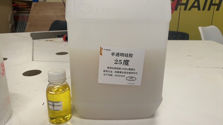
- Mixing ratio (by weight) : 100:2 (base rubber: curing agent)
- Operating Requirements: Stir thoroughly for 1-2 minutes; apply a release agent before casting to facilitate subsequent demolding.
- Full curing time: Approximately 2 hours.
- Precautions : The proportion of the curing agent is relatively small, so it is necessary to measure it as accurately as possible; insufficient stirring can easily lead to incomplete local curing.
1.2 Gypsum (Calcium Sulfate)
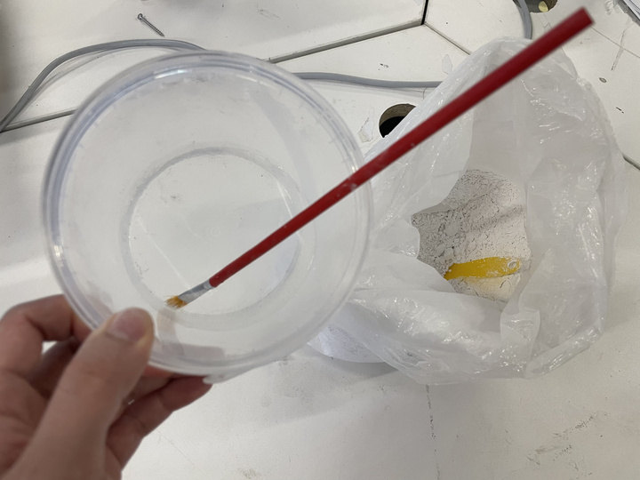
- Mixing ratio (by weight) : 3:1 (gypsum powder: water)
- Operating Requirements: First add water, then add gypsum powder; stir until it reaches a flowable state; first brush to fill in details, then pour the whole.
- Full curing time: Approximately 1 hour.
- Precautions : Gypsum dust is easily inhaled, so dust generation should be avoided during operation; gypsum is brittle after curing and is not suitable for slender or thin-walled structures.
1.3 Epoxy Resin (Crystal Resin)
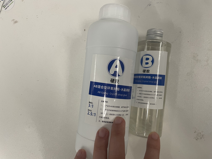
- Mixing ratio (by weight) : 3:1 (Adhesive A: Adhesive B)
- Operating Requirements : Weigh proportionally and stir thoroughly to minimize air bubbles.
- Full curing time: approximately 24 hours.
- Precautions : Epoxy resin may irritate the skin, so gloves must be worn during operation; direct contact with the skin should be avoided before curing; insufficient mixing may result in a sticky surface or incomplete internal curing.
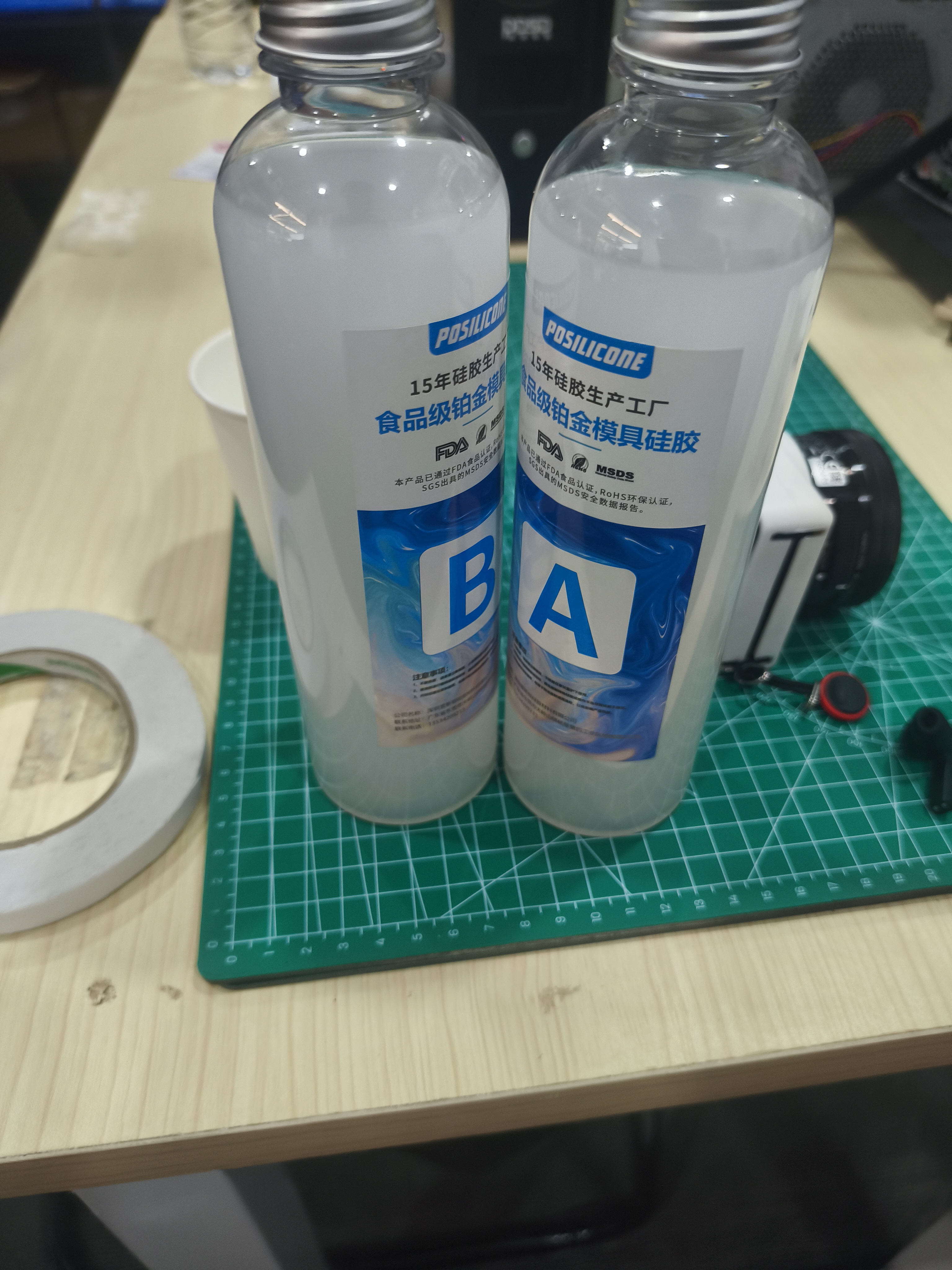
1.4 Food-grade Platinum Mold Silicone
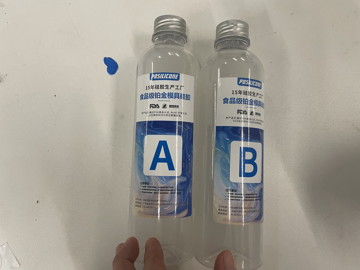
- Mixing ratio (by weight) : 1:1 (A glue: B glue)
- Operating Requirements: Mix Components A and B in equal amounts, stir thoroughly, and then pour.
- Full curing time: Approximately 6 hours.
- Precautions : The ratio is simple, suitable for making flexible molds; however, it is still necessary to avoid air bubbles and uneven mixing.
2. Comparison of Material Parameters
| Material | Usage | Mixing Ratio | Curing Time | Features |
|---|---|---|---|---|
| Industrial Silicone | Make flexible molds | 100 : 2 | Approximately 2 hours | Fast curing, but high requirements for weighing the curing agent |
| Gypsum | Make hard castings | 3 : 1 | Approximately 1 hour | Low cost, fast curing, but relatively brittle |
| Epoxy Resin | Make transparent / rigid castings | 3 : 1 | Approximately 24 hours | Good surface effect, but slow curing and requires attention to protection |
| Food-grade platinum silicone | Make flexible molds | 1 : 1 | Approximately 6 hours | Simple ratio, good demolding performance, suitable for detailed mold replication |
From the comparison, it can be seen that different materials are suitable for different stages. Silicone is more suitable for making molds because it is soft and easy to demold; plaster is suitable for rapid testing; epoxy resin is suitable for making hard, transparent, or decorative finished products, but it requires a longer curing time and more meticulous bubble treatment.
3. Comparison of Mold Manufacturing Processes
The group also compared several common mold manufacturing methods:
| Mold Manufacturing Method | Advantages | Disadvantages | Suitable Scenarios |
|---|---|---|---|
| CNC Milling Wax Blocks / Foam | High surface accuracy and good controllability | Requires cutting tools, machine tools, and machining time | High-precision molds, repeated casting |
| 3D Printed Prototype and Mold Replication | Fast production speed, free shape | FDM layer lines are obvious and require post-processing | Rapid Prototyping, Small-Scale Model |
| Laser Cutting Mold Frame + Prototype Mold Replication | Low cost, flexible setup | Suitable for simple mold opening, not suitable for complex curved surfaces | Planar or bas-relief model |
The process used for this individual assignment is 3D printing prototype + silicone mold making + epoxy resin casting . This process is suitable for making small graphic cases, has a low operational threshold, and facilitates observing the mold making and casting processes.
Individual Assignment
1. Design Objectives
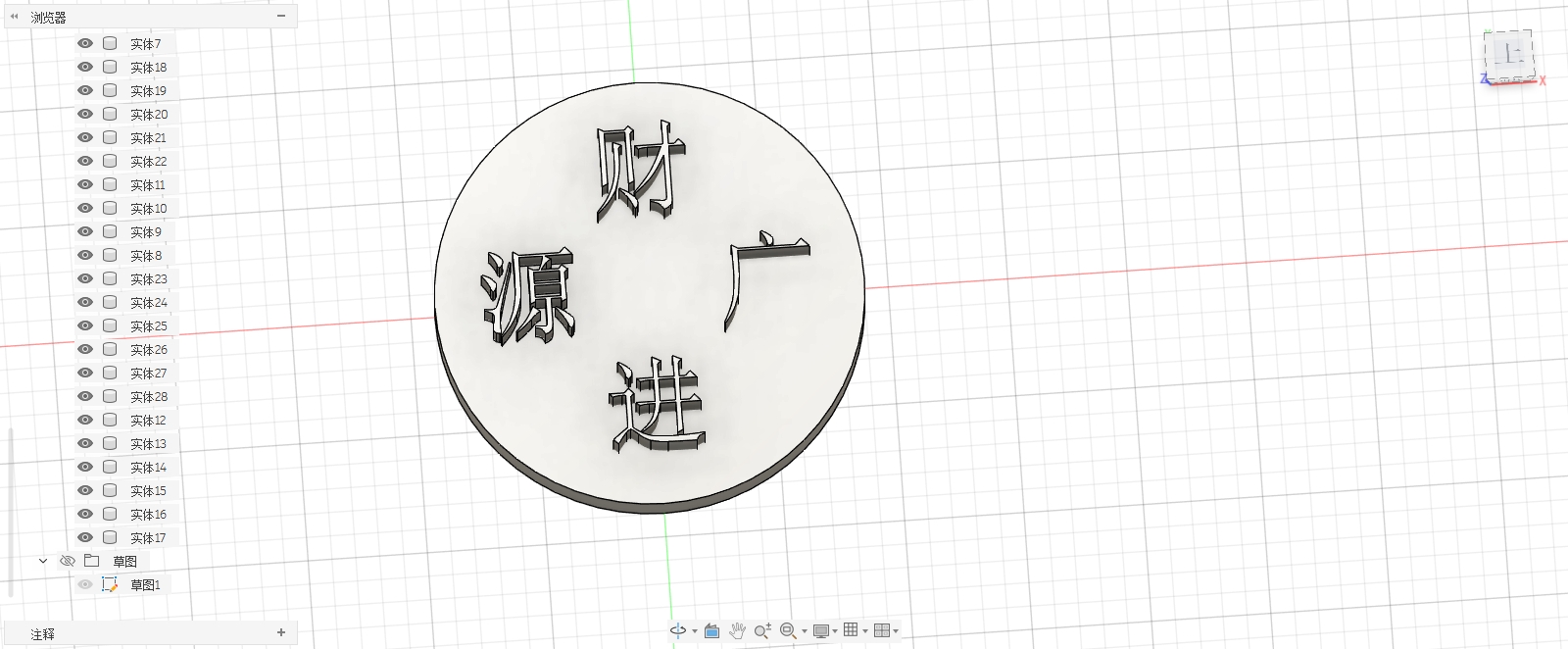
For this week's personal assignment, I made a small relief casting with the words "May wealth pour in" inscribed on it. Its final form is a square decorative plaque: a flat thin plate at the bottom, with the four characters "May wealth pour in" and simple decorative protrusions on the front. This model was first created as a master mold through 3D printing, then replicated into a negative mold using silicone, and finally cast into shape using epoxy resin.
When designing, I didn't make it into a complex three-dimensional ornament but chose a low-relief structure. The reason is that the focus this week is on molding and casting, and the model not only needs to look good but also be suitable for mold making, pouring, and demolding. Low-relief can test the replication ability of silicone for text details while not creating overly severe undercuts, making it suitable for using an integrated open mold.
The final model size is approximately 20 mm × 20 mm × 3 mm . This size is suitable for classroom production: the amount of silicone and resin used is not large, the curing time is controllable, and the finished product is not prone to breakage due to being too thin.
2. Fusion 360 Modeling Process
2.1 Establish Parameters
I first set the units to mm in Fusion 360, and then determine several basic dimensions based on casting and printing requirements:
| Parameter | Value | Function |
|---|---|---|
| Baseplate Length | 20 mm | Control the overall outer frame size |
| Baseplate Width | 20 mm | Make the model a decorative plaque close to a square |
| Bottom plate thickness | 3 mm | Ensure that resin parts have basic strength while not wasting materials |
| Relief Height | 0.6-0.8 mm | Make the text clearly embossed while avoiding difficulty in demolding |
| Edge Chamfer | 0.3-0.5 mm | Reduce sharp corners to facilitate demolding and post-processing |
| Text Margin | 4-6 mm | Avoid text being too close to the edge, which may lead to a weak mold |
These parameters are designed to enable the model to meet the requirements of three processes simultaneously: 3D printing, silicone mold making, and resin casting. If only the on-screen appearance is considered, the text can be made very thin and tall; however, during actual casting, overly thin strokes are prone to breakage, and excessively high reliefs increase the risk of undercuts. Therefore, it is necessary to control the relief height and stroke spacing.
2.2 Draw the base plate sketch
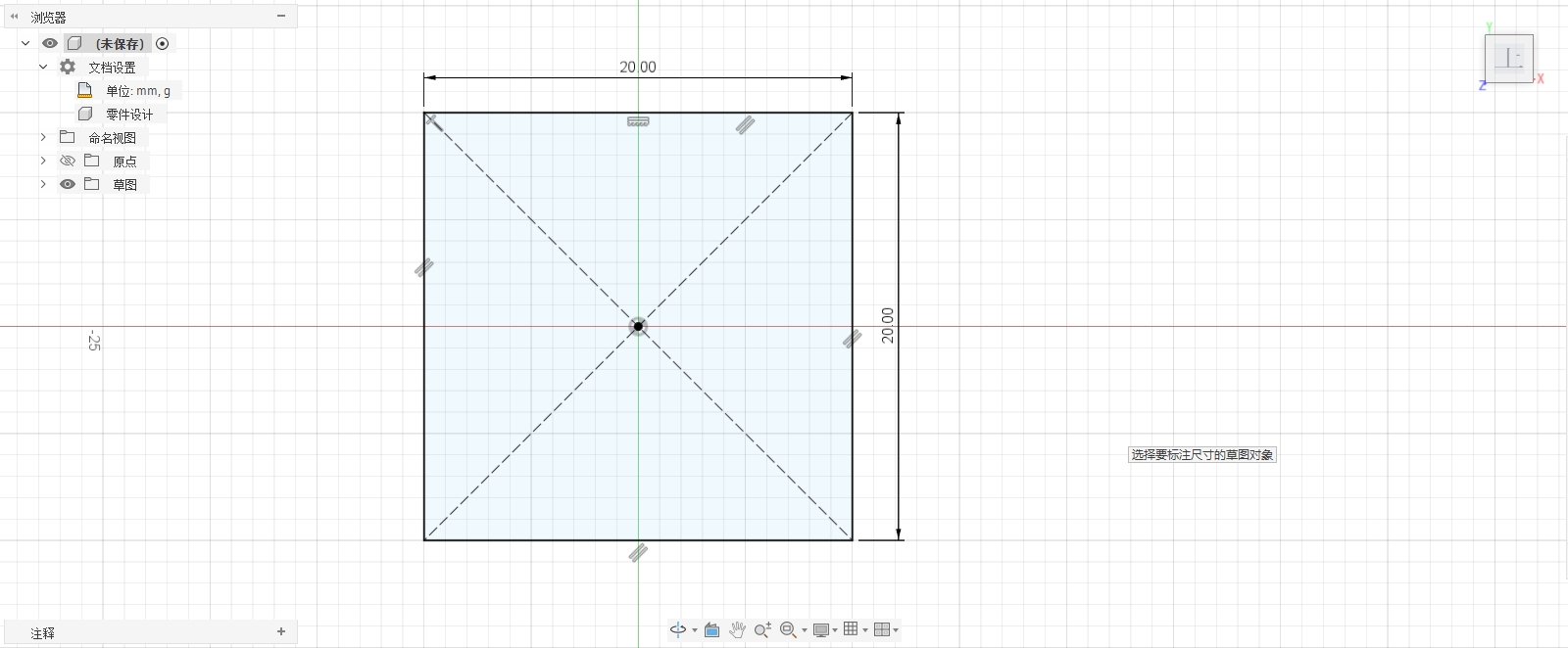
The first step is to create a sketch on the XY plane, using the center rectangle tool to draw a 20 mm × 20 mm square. The advantage of using the center rectangle is that the model center will align with the origin, making it easier to maintain symmetry when placing text and decorations later.
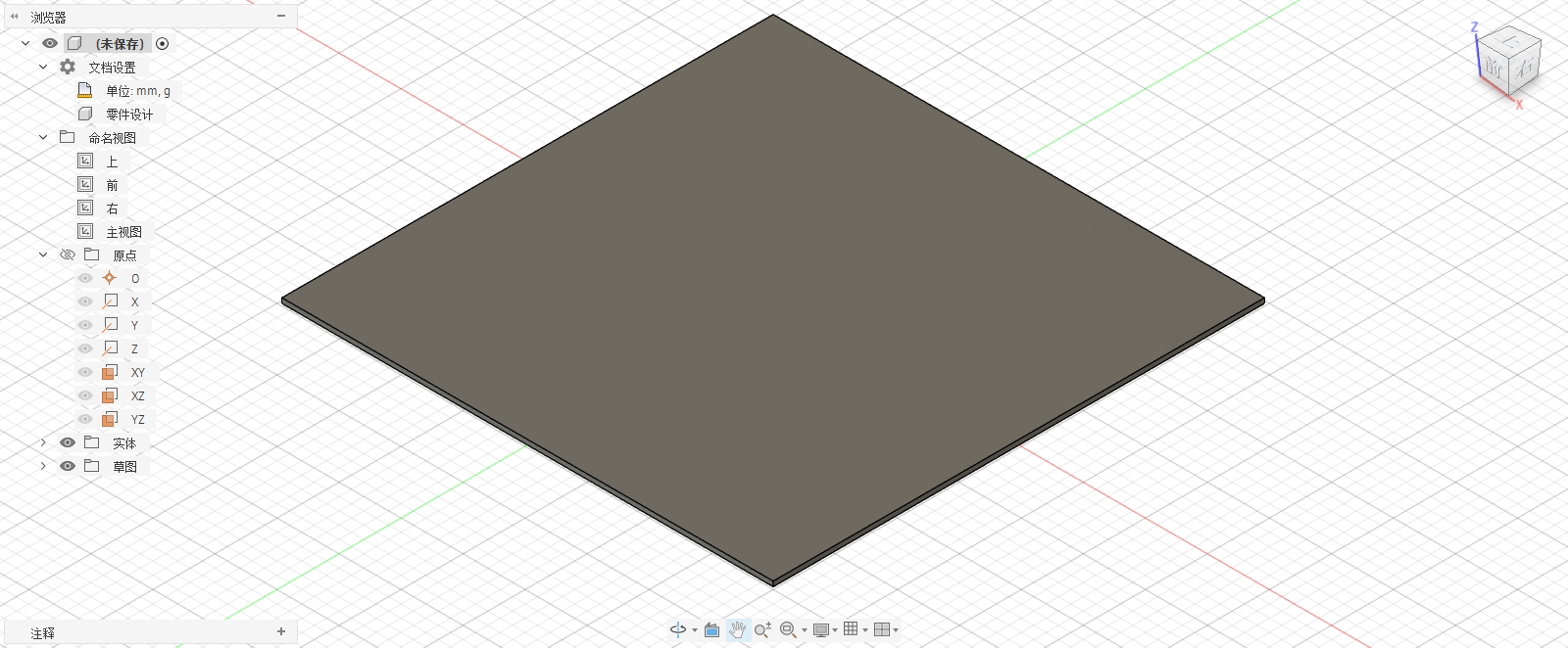
After completing the sketch, I extruded this square upward 2 mm , resulting in the base plate. This base plate is the main body of the entire casting and also the bearing surface for the subsequent text relief and border.
To avoid the edges of the finished product being too sharp, I added a small chamfer to the outer edge of the base plate. The chamfer not only improves the feel but also prevents the silicone from being easily damaged by sharp edges during demolding.
2.3 Design the outer frame and safety margins
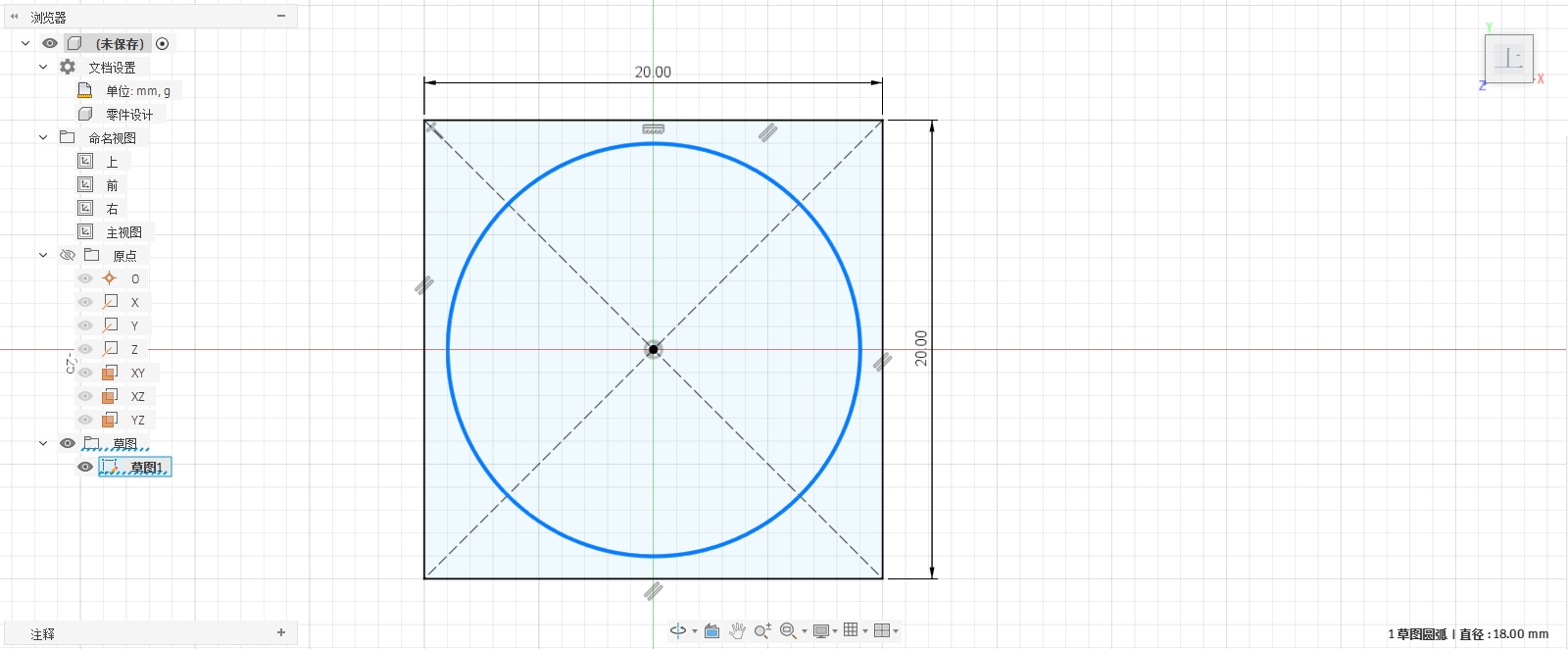
After the base plate is completed, I re-create a sketch on the upper surface and use the offset tool to offset a circle inward from the outer edge to form a safe area for text and decoration. This safety margin is approximately 4-6 mm.
The reason for setting margins is that if the text is too close to the edge, the corresponding position of the silicone mold will become thinner, making it prone to deformation during demolding; when resin is poured, the edge is also more likely to have material shortages or air bubbles. Therefore, I placed the main text in the middle area, leaving a continuous border around it.
If a more prominent decorative effect is desired, the border can also be made slightly raised. I adopted the idea of low relief, ensuring that the height of the border does not exceed that of the text, so that the overall front surface remains relatively easy to mold.
2.4 Create the text "May wealth pour in"
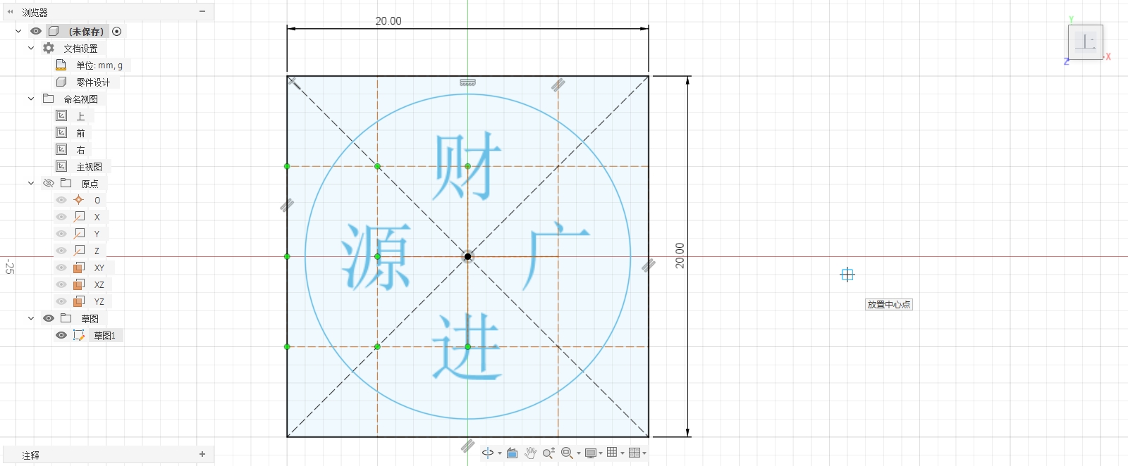
Next, create a new sketch on the upper surface of the base plate, and use the Text tool to input "Cai Yuan Guang Jin". To make the text clearly visible within the 20 mm card surface, I placed the text in the central area and adjusted the font size to ensure sufficient spacing between the four characters.
When designing the text, I mainly considered three points:
- The font should not be too thin, otherwise fine strokes are prone to missing during 3D printing and resin casting;
- The font should not be too complex, otherwise air bubbles are likely to get trapped in the details of the silicone;
- Spacing should be left between characters to facilitate the entry of silicone into the concave-convex edges.
In Fusion, text objects themselves are not suitable for directly serving as long-term processable contours, so I converted the text into sketch contours. After conversion, the strokes of each character become selectable closed contours, which can be individually extruded into reliefs later.
2.5 Extrude text into a low relief
After completing the text outline, I select the closed area of the text and extrude it upward 3 mm . This height is the key to this design:
- If the height is too low, the text will not be obvious after mold turning and pouring;
- If the height is too high, the edges of the text will turn into deep grooves, making demolding and venting more difficult;
- A 3 mm bas-relief can visually create distinct levels while still being suitable for an integrated silicone mold.
This way, no separate parts will appear during 3D printing of the master mold, and it also facilitates subsequent silicone replication.
2.6 Processing text edges and details
After the text stretching was completed, I inspected the stroke edges. If the edges are completely sharp, silicone will accurately replicate them, but the edges are also more likely to chip during the demolding of resin parts. Therefore, I made slight chamfers or rounded corners on the obviously sharp positions.
The chamfer should not be too large, otherwise the text will become blurry; nor should it be left completely untreated, otherwise the edges of the model will be too sharp. This time, a very small chamfer is used, just to slightly soften the edges of the strokes while maintaining the recognizability of "Cai Yuan Guang Jin".
This part is the design adjustment for casting. It differs from ordinary 3D printing: 3D printing can accept many sharp details, while silicone mold making and resin demolding require more consideration of material flow and demolding forces.
2.7 Check undercuts and demolding directions
After the modeling is completed, I check the demolding direction of the model from the side. The back of this model is flat, while the front is a shallow relief that protrudes upward. Therefore, the back can be attached to the bottom of the mold frame, allowing the silicone to cover it from above. During demolding, the prototype is removed from the silicone in the vertical direction.
I specifically checked whether there were deep undercuts between the strokes of the text. Since the text only protrudes upward and has no structure that undercuts laterally, a one-piece open mold can be used. If there are lateral undercuts in the model, it will be necessary to change to a two-piece mold or modify the model structure.
2.8 Export STL and Prepare for Printing
After confirming that the model has no obvious issues, I exported the model as an STL file for 3D printing the master mold. When exporting, I selected a higher precision to avoid text edge distortion caused by overly coarse meshes. After exporting, I imported it into slicing software to check the dimensions and orientation.
The printing orientation is selected as follows: the back of the base plate is attached to the printing platform, with the text relief facing upwards. This ensures a flat bottom surface, facilitating subsequent fixing to the bottom of the mold frame; the text on the front side also does not require support, reducing surface damage caused by support removal.
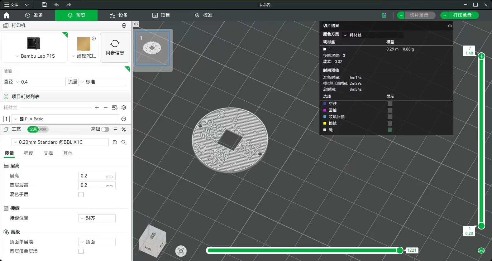
The slicing parameters are as follows:
- Layer height: approximately 0.1 mm, used to reduce layer lines and preserve text details;
- Fill rate: 20% to 30%, ensuring the master mold has sufficient strength;
- Number of outer walls: Appropriately increasing the number of outer walls improves edge quality;
- Support: The model is a low-relief planar part and does not require complex support;
- Printing orientation: Back side down, embossed text up.
3. Mold Design for Casting
3.1 Select the integrated open mold
Based on the model structure, I choose an integrated open silicone mold. The parting method is as follows: the back of the model is fixed to the bottom of the mold frame, with the front relief facing upwards, and silicone is poured from above to cover the entire model. After curing, the master mold is removed, leaving a negative pattern of "May wealth pour in" in the silicone.
The reason for choosing this mold solution is:
- The back of the model is flat and can serve as a natural parting surface;
- All front details face the same direction;
- The relief height is relatively shallow, with no obvious undercuts;
- The model has a thickness of only about 3 mm, with a short demolding distance;
- Subsequent resin can be directly poured from the open side without the need for complex gates.
If this model were to be made into a complete three-dimensional ornament, it might require two-piece molds, locating tenons, gates, and vents. However, since this model is a low-relief plaque, a one-piece open mold is simpler and more suitable for classroom production.
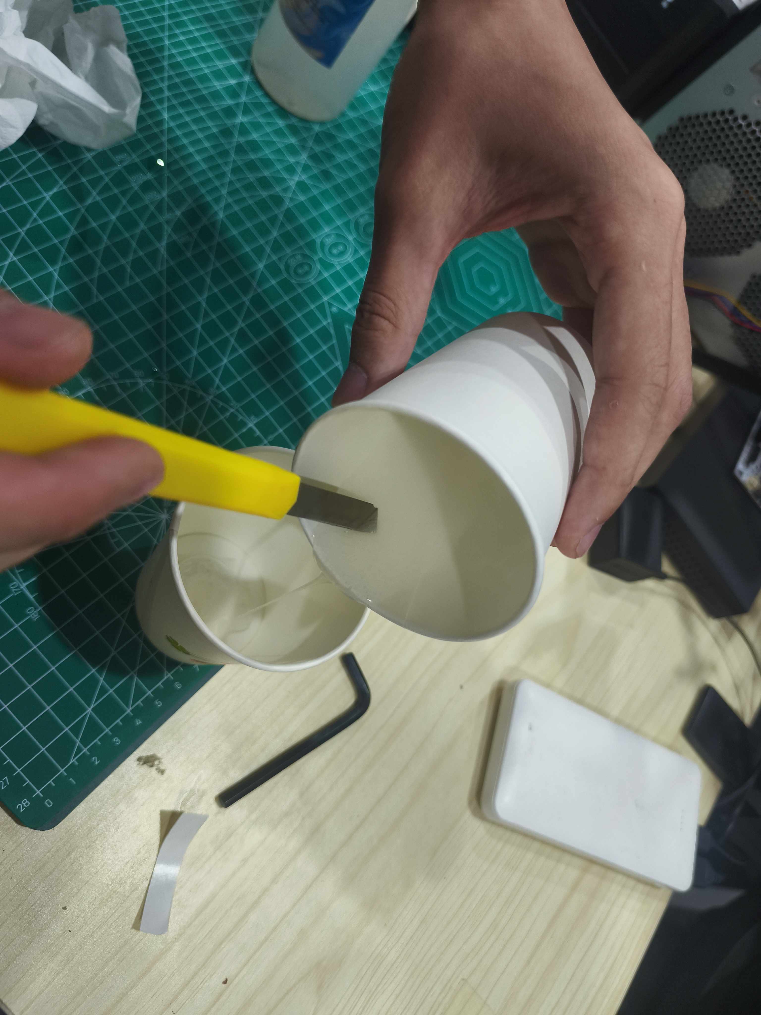
3.2 Mold Frame and Silicone Thickness
The mold frame size needs to be one circle larger than the perimeter of the model. I reserve the thickness of the silicone outside the edge of the model to avoid the mold edge being too thin. Too thin silicone will lead to two problems: First, it is prone to tearing during demolding; Second, the mold will deform during resin casting, affecting the edge of the finished product.
A certain thickness of silicone also needs to be left at the top of the model. Although this model is only 3 mm thick, the silicone layer should not just cover the model but should be raised a certain distance above it to ensure the mold has sufficient strength.
3.3 Pouring and Venting Design
Since an open mold was ultimately adopted, there was no need to separately design a closed gate during resin casting. However, to reduce air bubbles, I designed the pouring direction in the process: slowly pour from one side of the mold, allowing the resin to gradually flow over the text details, rather than pouring directly above the text.
The edges of text strokes are the most likely places to trap air bubbles. Therefore, whether it is silicone mold making or resin casting, it is necessary to pour slowly and gently tap the mold frame or mold to allow the air bubbles to rise.
4. Prototype Post-Processing and Mold Frame Preparation
The surface of FDM printed parts will have layer lines and a small amount of burrs. If directly used for mold making, these marks will be replicated by the silicone and then appear on the resin castings. Therefore, before mold making, I first clean the edges and surface of the prototype.
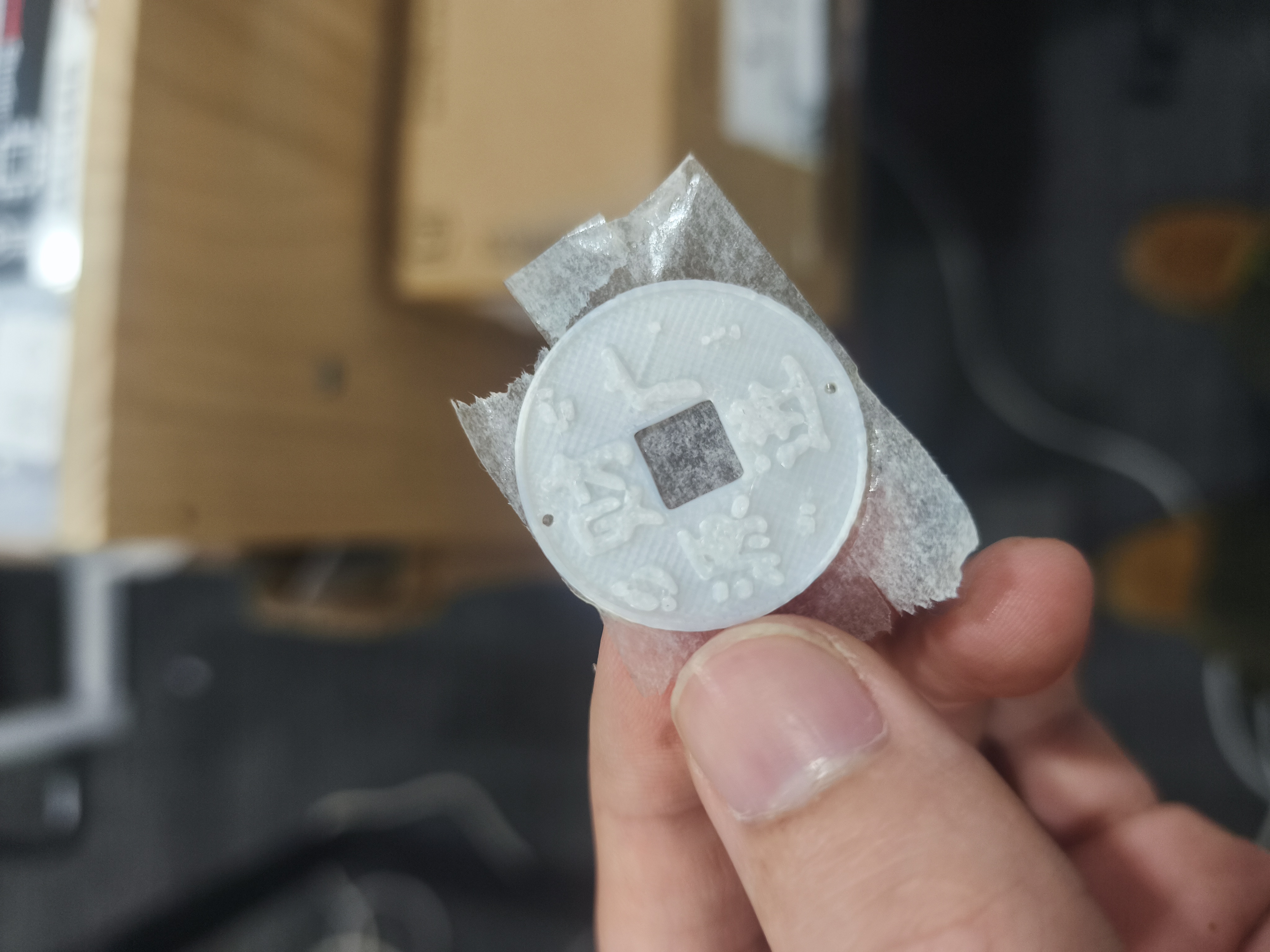
During processing, I focused on cleaning up burrs and obvious wire drawing on the outer frame, but did not over-grind the text area. Since the text relief itself is relatively thin, excessive grinding may blunt the edges of the strokes, affecting the recognition of the final casting.
The mold frame size needs to be one circle larger than the model outer frame to ensure sufficient silicone thickness around the model. Since the back of the model is flat, I fixed it to the bottom of the mold frame to prevent the prototype from floating or moving during silicone pouring.
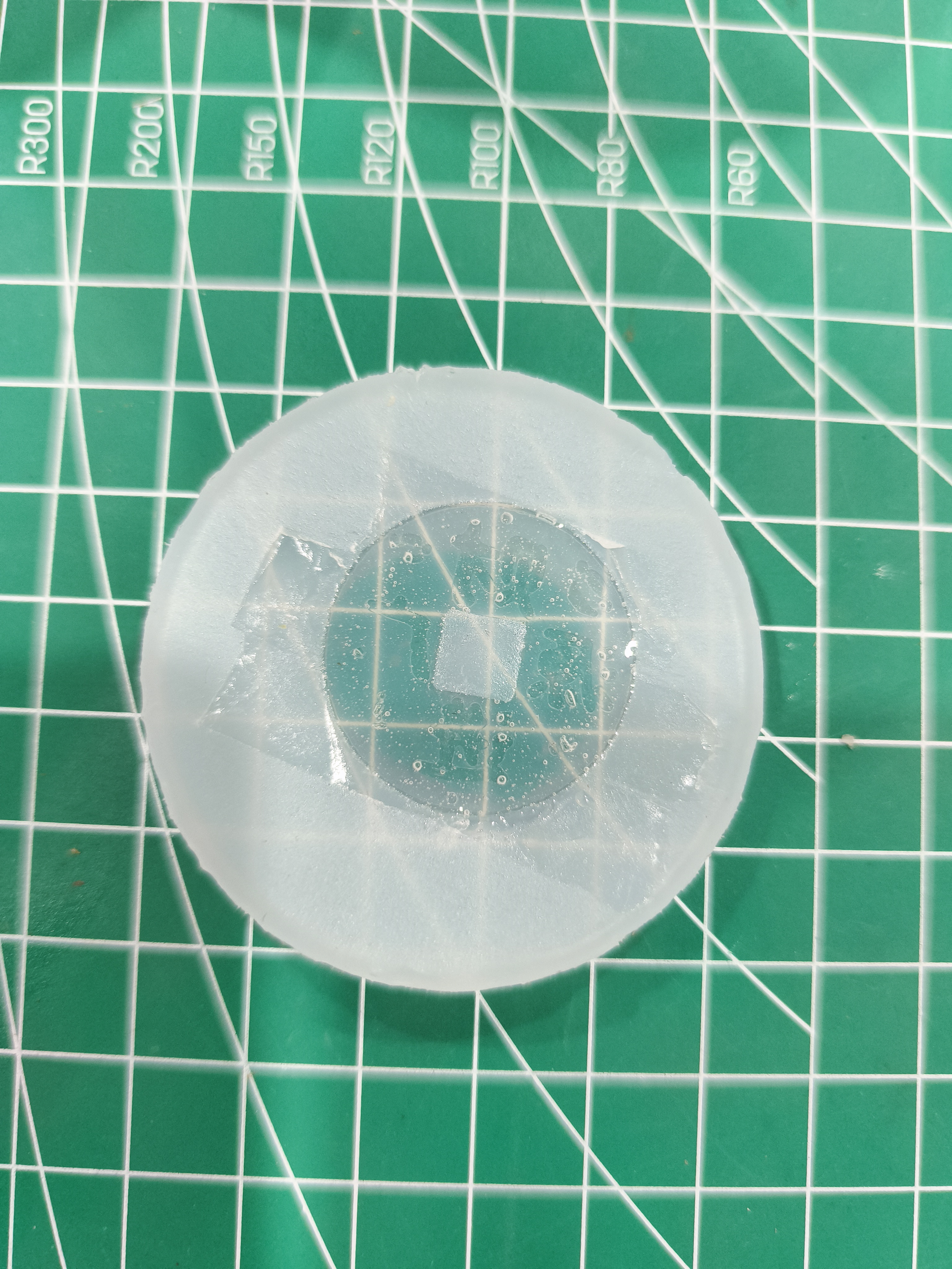
5. Silicone Mold Making
This time, food-grade platinum silicone is used, with the ratio of Component A to Component B being 1:1 by weight. The quality of the silicone mold directly determines the quality of the final casting, so the ratio, mixing, and defoaming are all important.
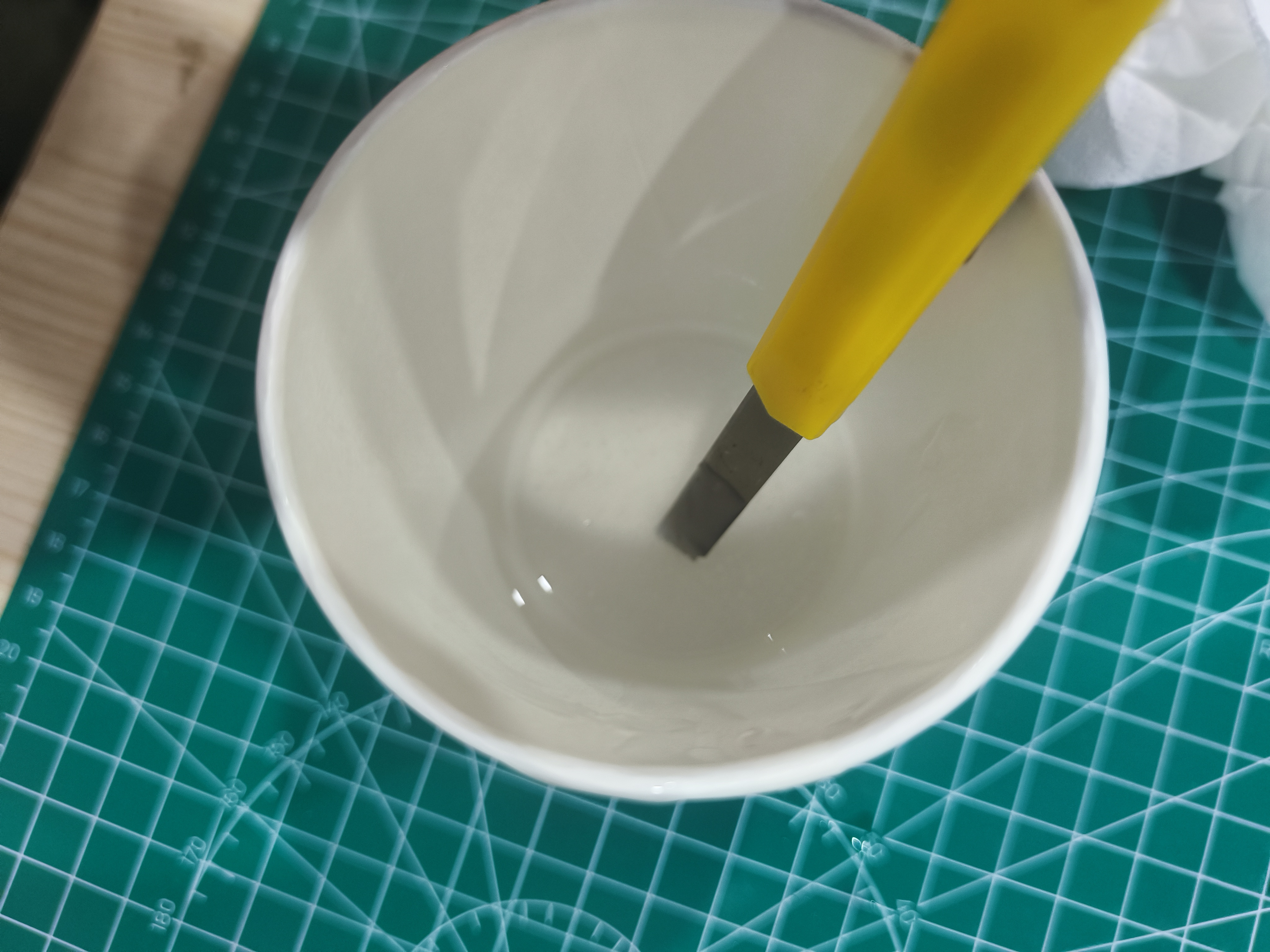
I first weigh Glue A and Glue B using an electronic scale, then pour them into a mixing cup. During mixing, stir slowly along the cup wall, scrape the bottom and sides to ensure the two materials are evenly mixed. The mixing speed should not be too fast, otherwise a large number of air bubbles will be introduced.
After the mixing is completed, I let the silicone stand for a while and gently tap the cup wall to help the large bubbles rise. Then, I first brush on the text and decorative details, and then slowly pour the silicone from the corner of the mold frame.
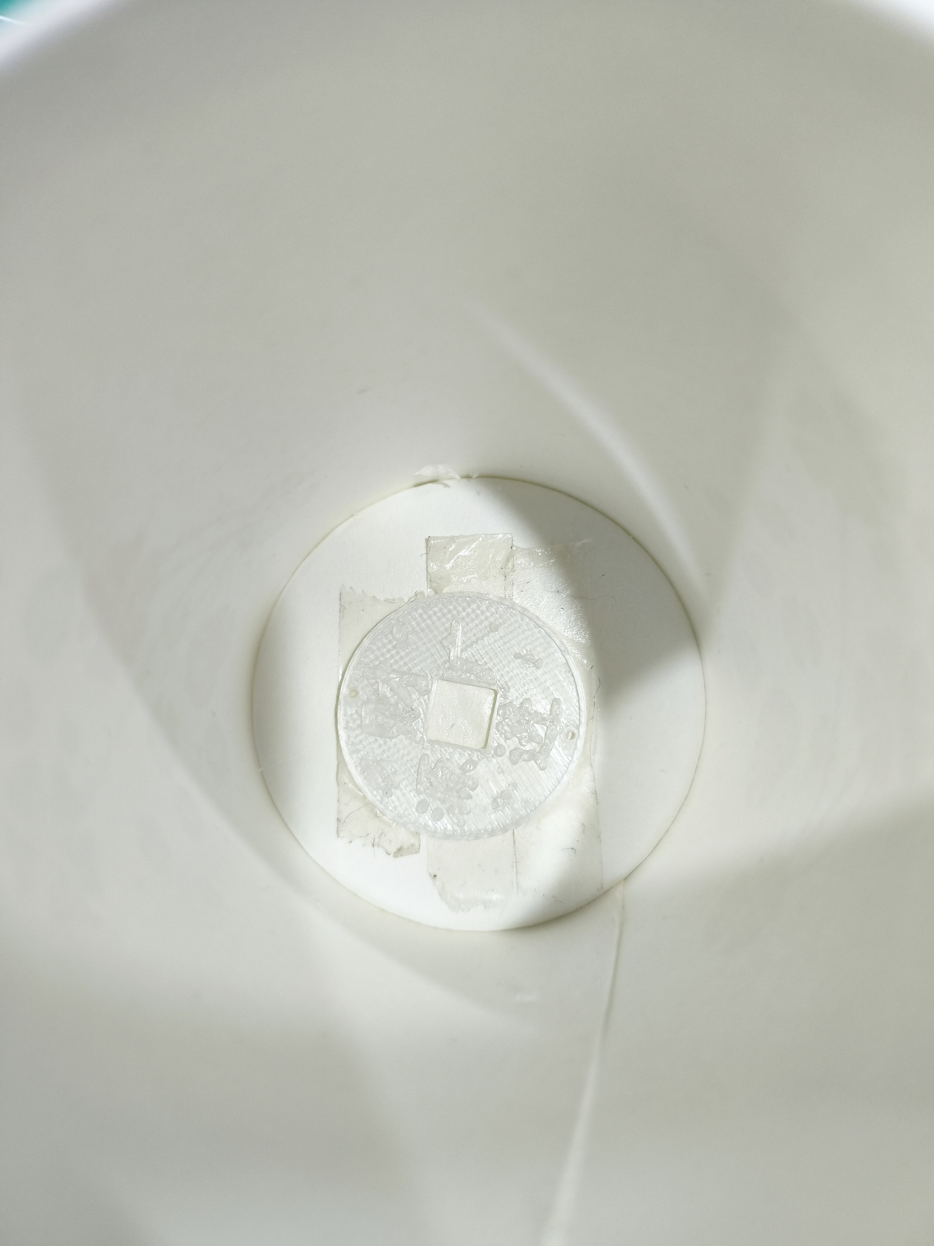
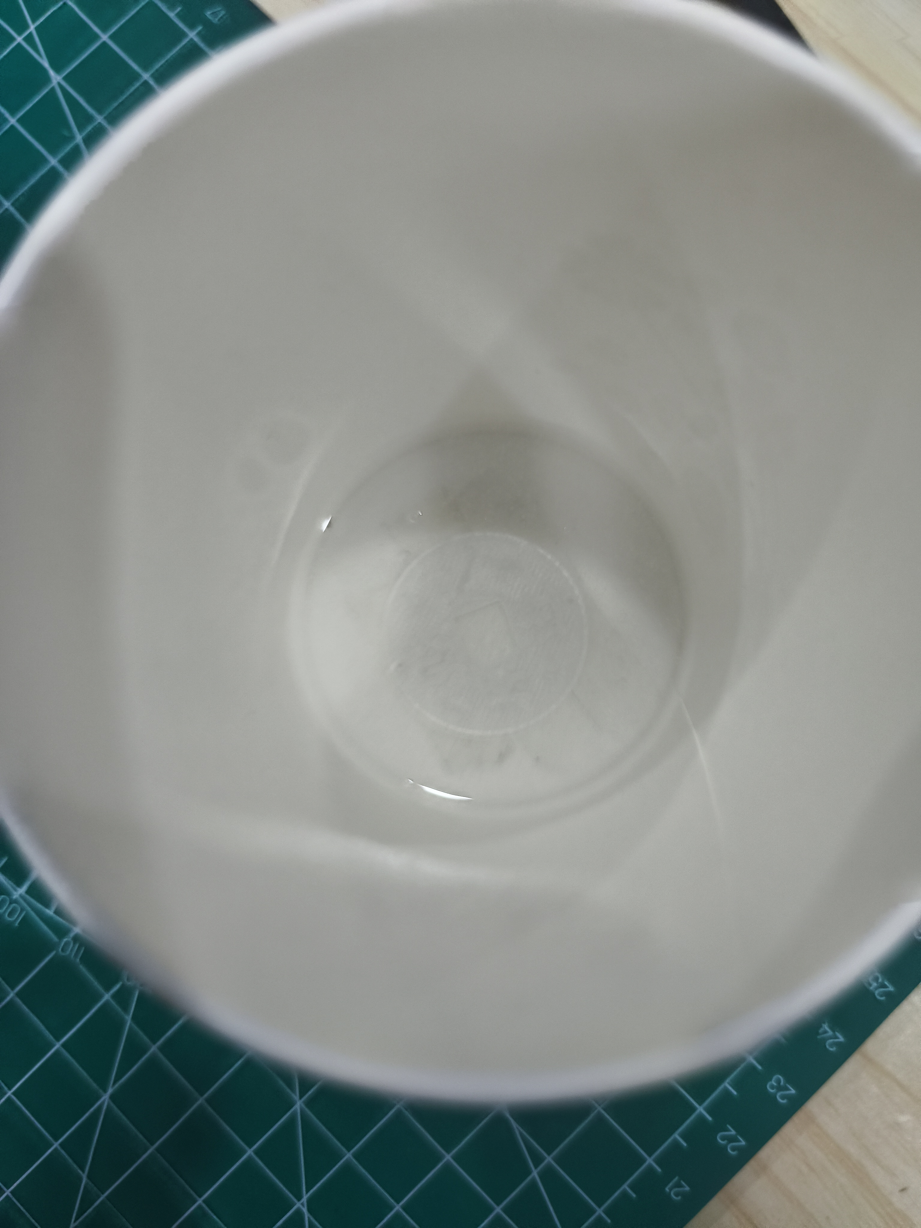
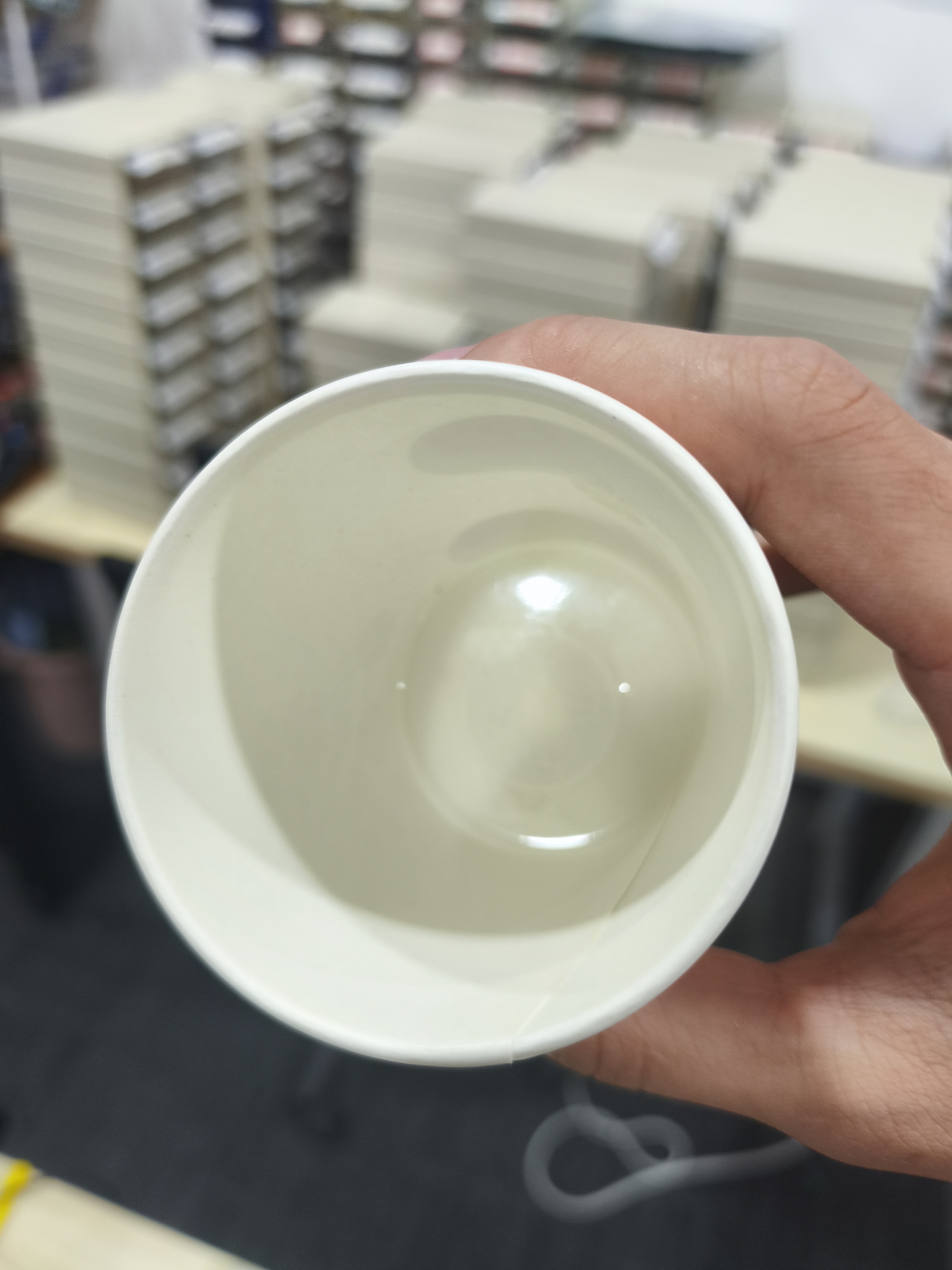
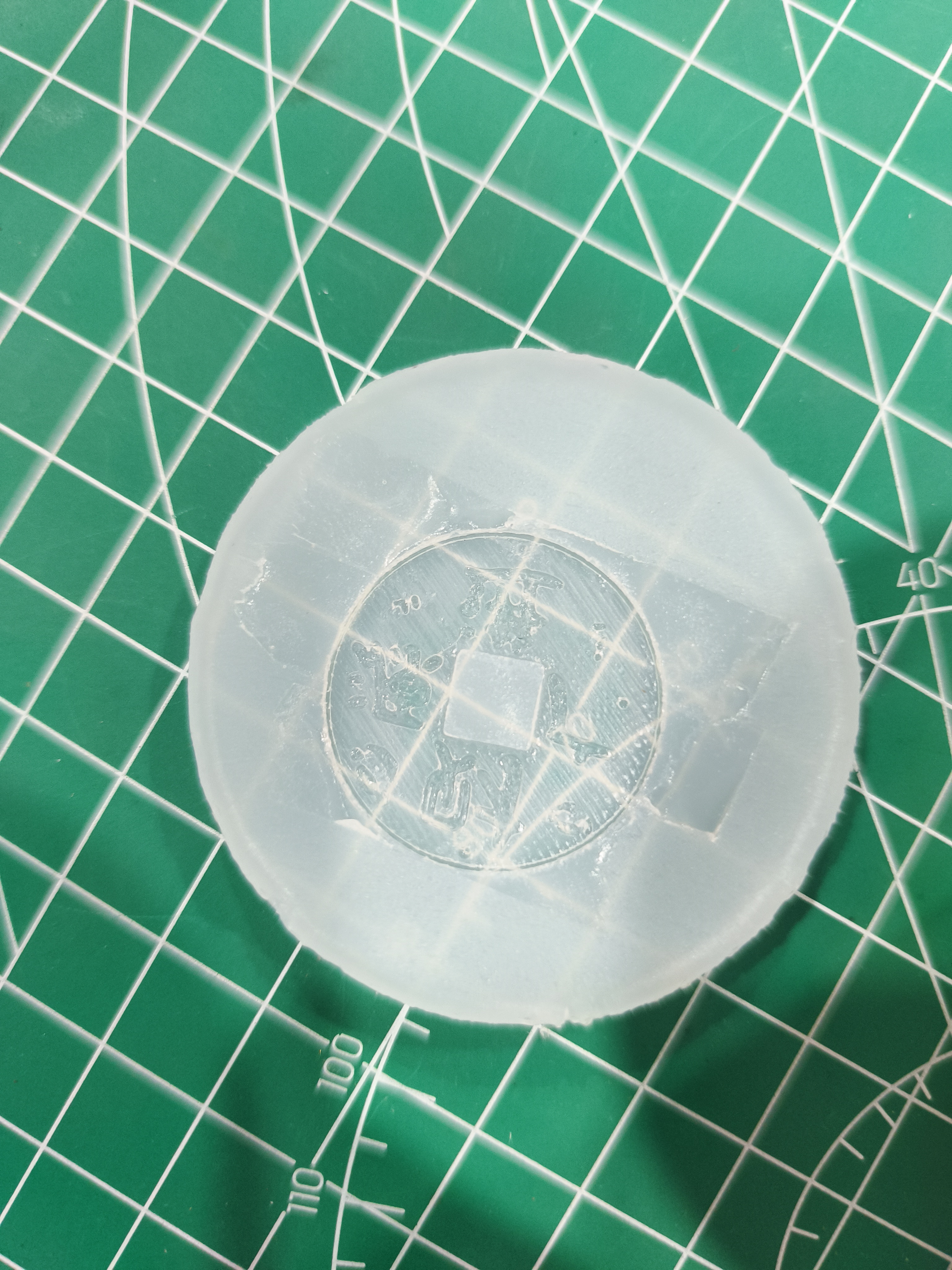
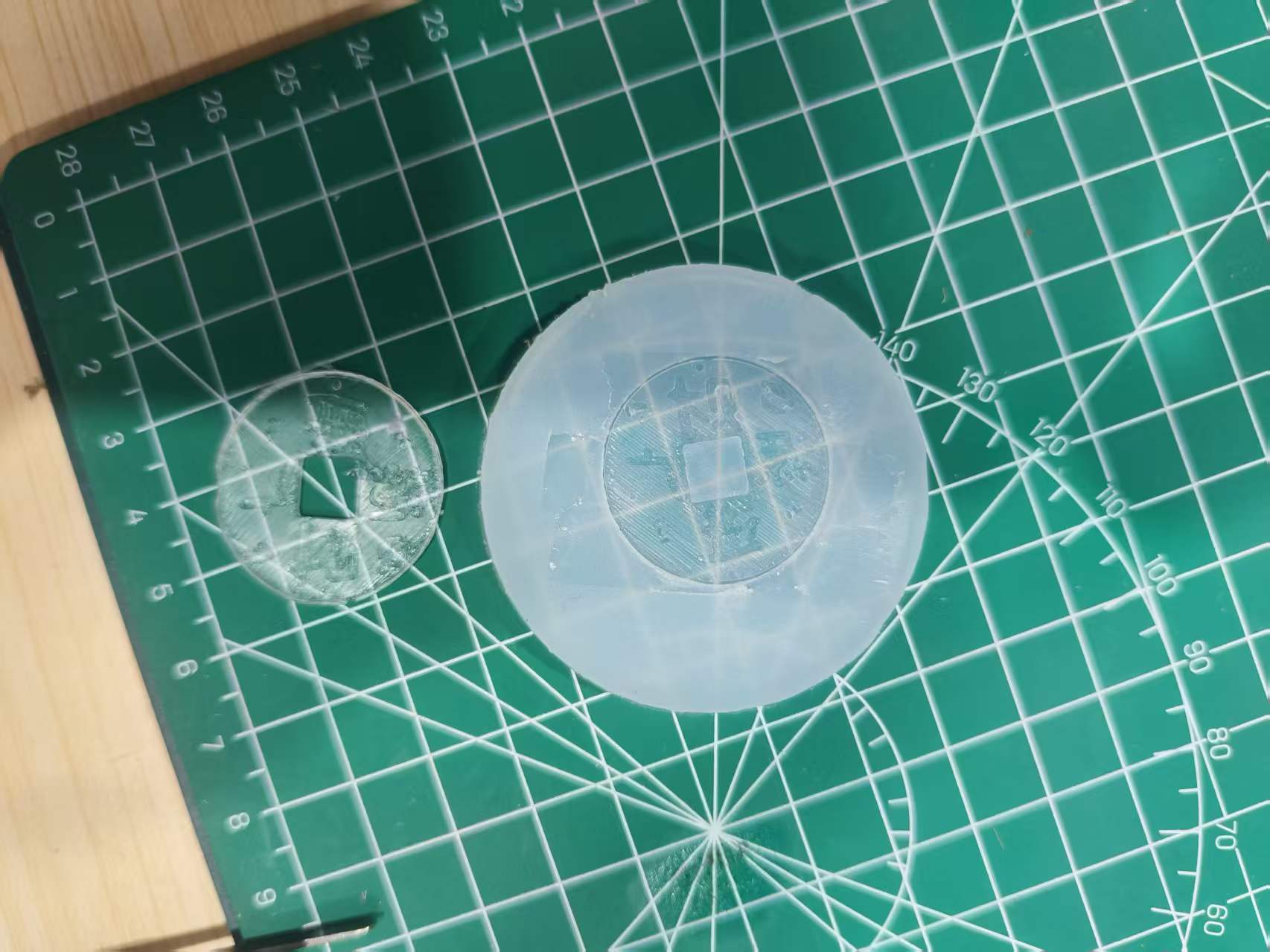
After the silicone pouring is completed, let it stand and cure at room temperature. During the curing process, try not to move the mold to avoid prototype displacement or ripples on the silicone surface. After curing is completed, remove the mold from the mold frame, then slowly remove the prototype to obtain a silicone mold with the intaglio pattern of "May wealth pour in".
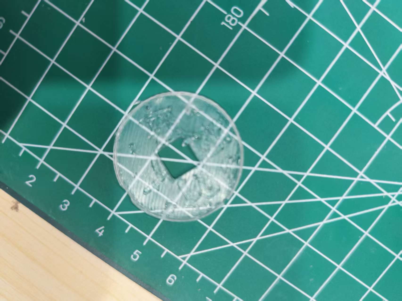
6. Epoxy resin casting
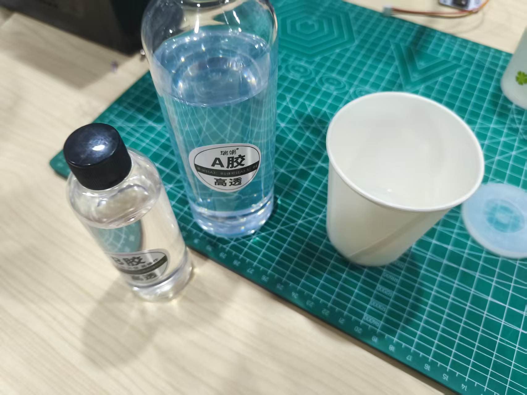
After the silicone mold is completed, I use epoxy resin for casting. Resin A and Resin B are mixed at a weight ratio of 3:1. Inaccurate mixing or insufficient stirring will result in incomplete curing or sticky surface of the resin.
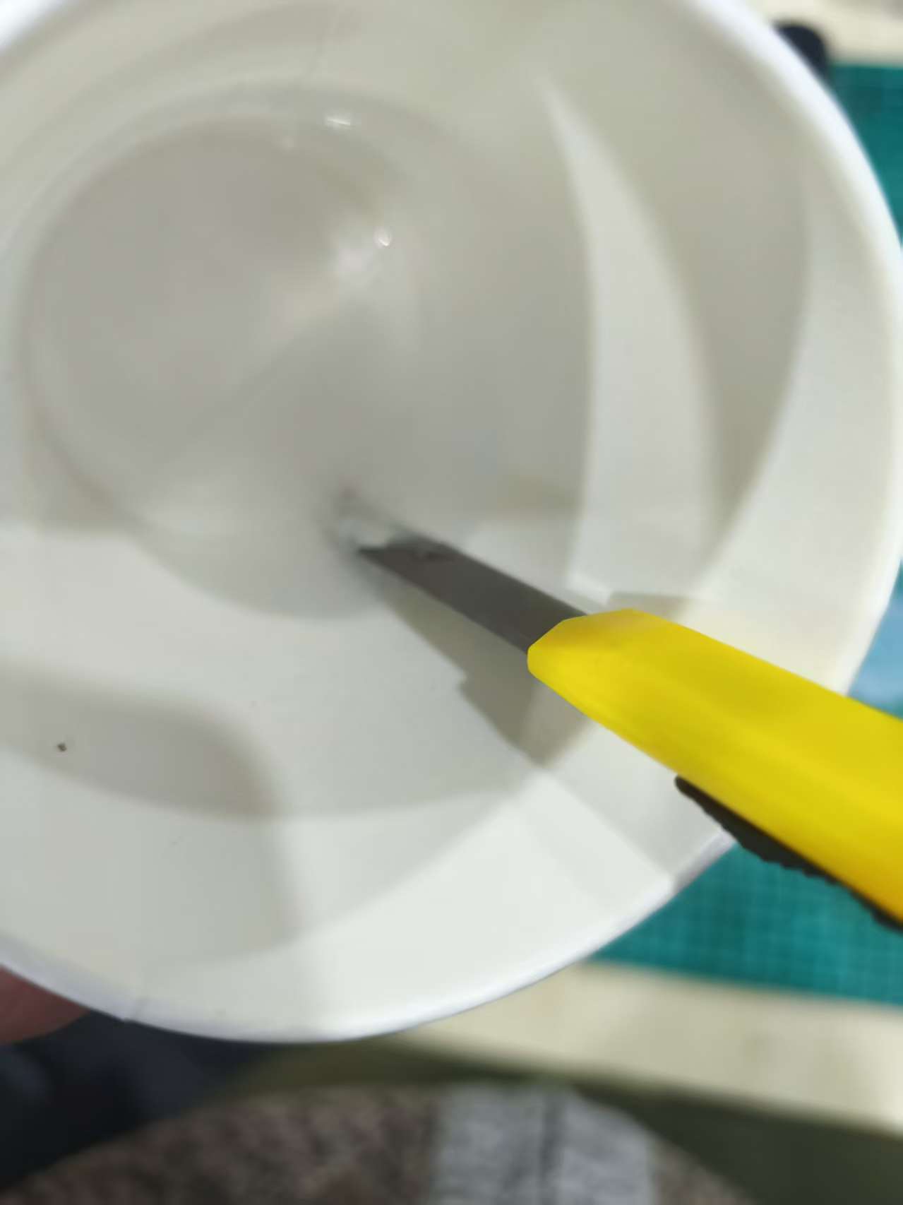
When stirring the resin, I use slow stirring and scrape the bottom and walls. After stirring, let the resin stand for a while to allow larger bubbles to rise. Since the finished product is a bas-relief, no complex gate is needed during pouring. I directly pour the resin slowly from one side of the open mold, allowing the resin to gradually cover the text details and the bottom plane.
During the injection process, tap the sidewall of the mold to help expel small air bubbles at the edges of the text. After the resin is filled, let it stand and cure at room temperature for about 24 hours. During the curing process, avoid movement and vibration, and prevent dust from falling onto the resin surface.
During the injection process, tap the sidewall of the mold to help expel small air bubbles at the edges of the text. After the resin is filled, let it stand and cure at room temperature for about 24 hours. During the curing process, avoid movement and vibration, and prevent dust from falling onto the resin surface.
7. Surface Quality and Problem Analysis
The main quality judgment points of this work are whether the text is clear, whether the edges are intact, and whether there are obvious bubbles on the surface. Since the prototype is made by FDM printing, layer lines may be replicated by the silicone, so prototype post-processing is important.
In this design, the one-piece open mold is more suitable for this low-relief model. It reduces the parting line and also lowers the risk of misalignment. The most important issue to note is bubble control, especially at the edges of text strokes. If bubbles in the silicone or resin remain in the details, the final casting will have missing corners or small holes.
To improve the surface quality, I adopted the following methods:
- Print the prototype with a smaller layer height;
- Clean burrs and wire drawing before mold turning;
- First paint the text details, then pour silicone overall;
- Both silicone and resin are stirred slowly;
- Slowly pour from one side during pouring;
- Tap the mold to help the bubbles rise.
8. Troubleshooting Common Issues
| Question | Possible Reasons | Solution |
|---|---|---|
| Text details are unclear | The layer height of prototype printing is too large, or the silicone has not penetrated into the details | Reduce the floor height, and apply a layer of silicone before mold flipping |
| There are air bubbles in the mold | Silicone is stirred too quickly or poured directly onto the model | Stir slowly, pour slowly from the corner, and perform vacuum defoaming when conditions permit |
| There are small holes on the surface of the resin part | Resin bubbles stay on the edge of the text | Let it stand for defoaming, tap the mold gently, and slowly inject from one side |
| Edge damage during demolding | Resin not fully cured or demolding too quickly | After curing for 24 hours, demold and slowly separate along the edge. |
| Surface replicates into lamellae | FDM prototype surface untreated | Print with a small layer height, and clean up burrs and obvious layer lines before mold replication |
9. Summary
Through this week's assignment, I have understood that the design of molding and casting is not just about creating a 3D model; it also involves ensuring that the model can be made into a mold, can be smoothly demolded, and can allow the material to fully replicate the details. For small shallow relief items like "May wealth pour in," with a flat back, relatively thin thickness, and no obvious undercuts, an integrated open silicone mold is a more reasonable option.
In this design, I focused on considerations such as baseplate dimensions, text relief height, edge chamfering, silicone thickness, pouring direction, and bubble control. The final process began with Fusion modeling, and through 3D printing of the prototype, silicone mold replication, and epoxy resin casting, the transformation from a digital model to a physical casting was completed.
Attachment
AI Assistance:
During the preparation of this documentation, ChatGPT (GPT-4) was used as a language assistance tool.
It helped with sentence polishing and translation from Chinese to English to improve readability and clarity.