Week 9 - Input Devices
Assignment
Group assignment:
Probe an input device(s)'s analog levels and digital signals Document your work on the group work page and reflect on your individual page what you learned
Individual assignment:
Measure something: add a sensor to a microcontroller board that you have designed and read it.
Summary
This week, I explored input devices,
1. A Hall sensor - The goal was to understand how the sensor detects magnetic fields and integrates with a microcontroller.
I used a Hall sensor with three pins: VCC, GND, and SIG, interfacing it with my PCB board from electronic production week.
I faced a challenge with the Hall sensor, which was not reading the correct value and I had to replace it with another one.
2. A ultrasonic sensor - The goal was to understand how the sensor measures distance and integrates with a microcontroller.
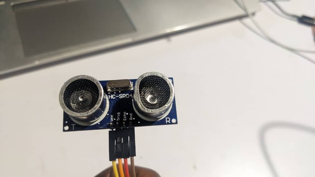
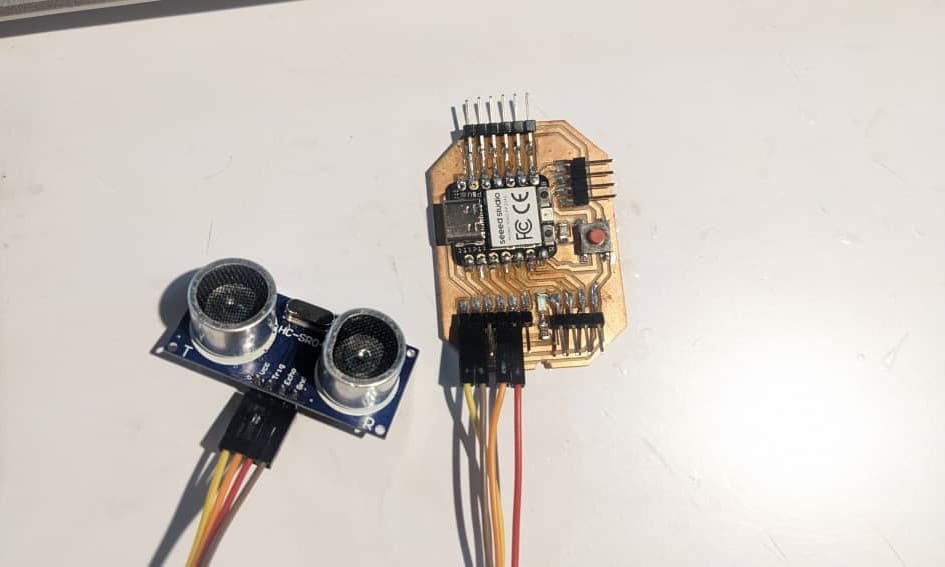
I used an ultrasonic sensor with four pins: VCC, GND, ECHO and TRIG, interfacing it with my PCB board from electronic production week.
Group page: Input Devices
Connection
Hall Sensor Digital Pin (SIG) to D3 on Xiao RP2040
VCC to 3.3V
GND to GND

I monitored the sensor data through the Arduino Serial Monitor while testing it with a magnet to observe changes in the readings.
Codes
                #define HALL_SENSOR_PIN A0

                void setup() {
                  Serial.begin(9600);
                }

                void loop() {
                  int hallValue = analogRead(HALL_SENSOR_PIN);

                  Serial.print("Hall Sensor Value: ");
                  Serial.println(hallValue);

                  delay(200);
                }
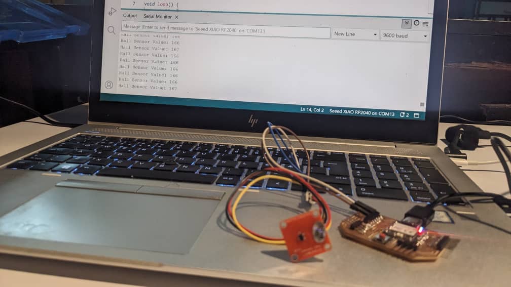
The Hall Sensor readings on serial monitor kept same numbers when I moved magnet around. This was due to sensor malfunctioning.
I replaced with another hall sensor keeping the same pin connection and codes.
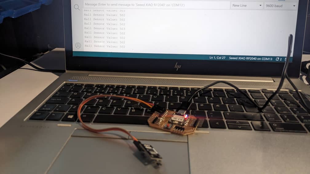
The readings of the new hall sensor changed accordingly:
North pole closer - Hall Value increase
South pole closer - Hall Value decrease
Ultrasonic Sensor
I also used a ultrasonic sensor as an input device to measure the distance. It has two main parts the transmitter and the receiver.
I have to send a sound wave from the transmitter and the signal will bounce back to the receiver once it hits an object.
From there I will be able to calculate the distance cover using the formula: Distance = velocity*time and velocity = speed of sound
Pin Connection
TRIG to D1
ECHO to D2
VCC to 3.3V
GND to GND
Codes
                #define TRIG D1
                #define ECHO D2

                void setup() {
                  pinMode(TRIG, OUTPUT);
                  pinMode(ECHO, INPUT);
                  Serial.begin(9600);
                }

                void loop() {
                  digitalWrite(TRIG, LOW);
                  delayMicroseconds(2);
                  digitalWrite(TRIG, HIGH);
                  delayMicroseconds(10);
                  digitalWrite(TRIG, LOW);

                  long duration = pulseIn(ECHO, HIGH);

                  int distance = (duration * 0.034 / 2);

                  Serial.print("Distance: ");
                  Serial.print(distance);
                  Serial.println(" cm");

                  delay(200);
                }
After uploading my codes to the microcontroller, I first checked the distance on serial monitor without an object placed
in front of the sensor.
Then after I placed the cutter as an object broking signal and checkek again the monitor for distance.
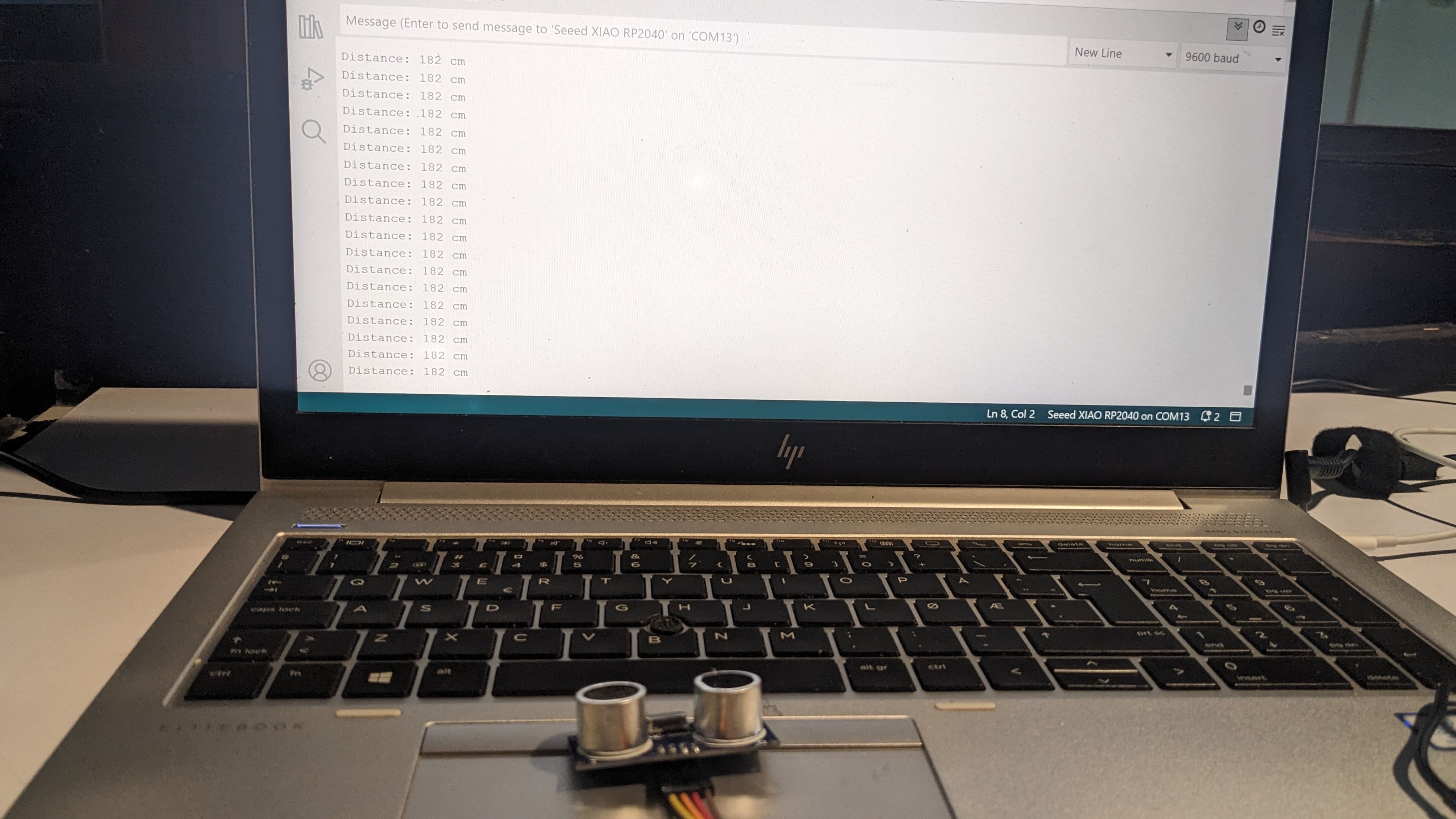
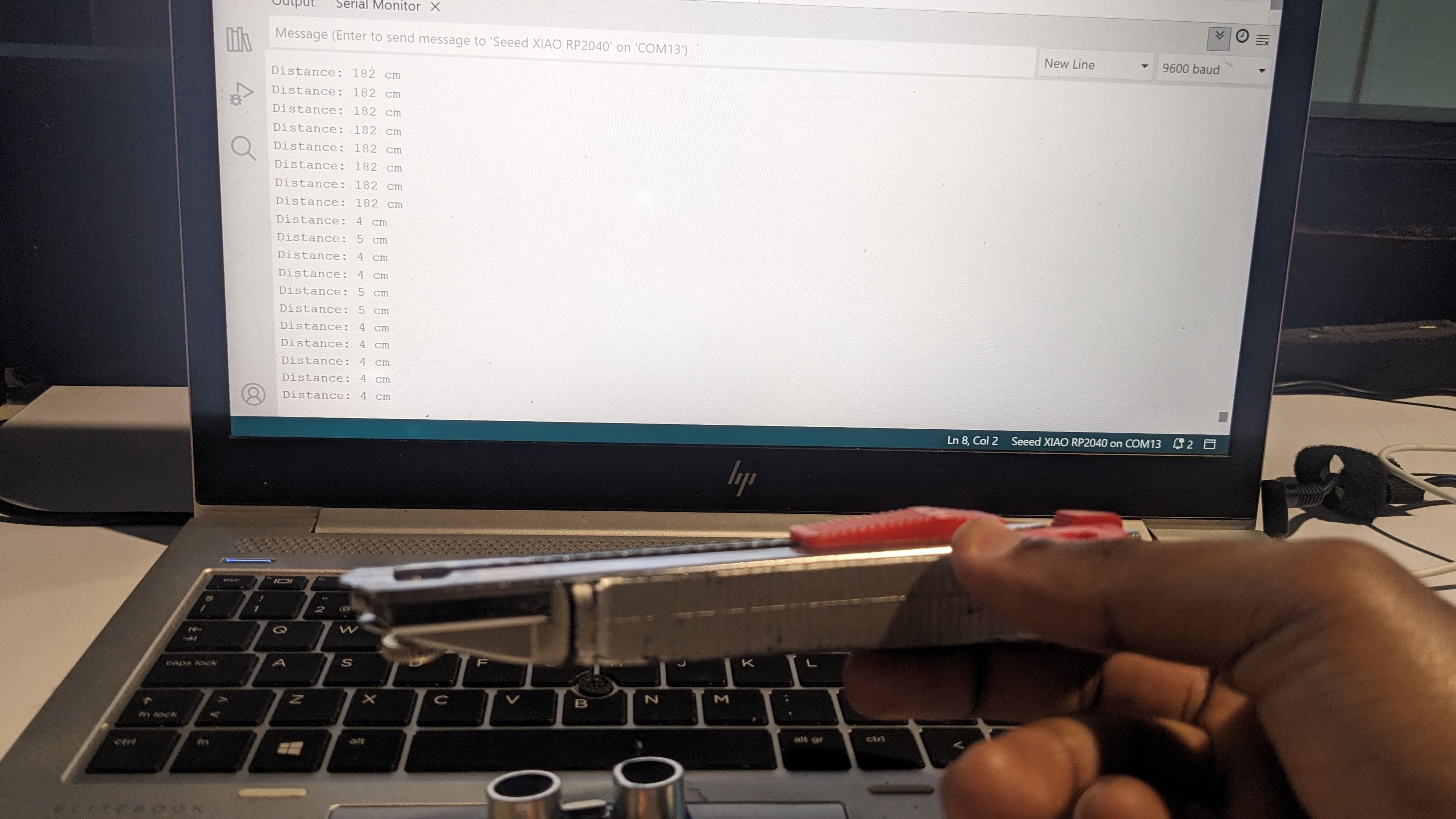
The sensor was working properly, I then kept changing the distance to see the effect on the distance.
Files
Hall Sensor Codes
Ultrasonic Sensor Codes