Week 15 - System Integration
Assignment
Design and document the system integration for your final project
Project Overview
My project aims to create a bionic hand that replicates human finger movement based on hand gestures. Initially, the design relied on EMG sensors to detect muscle signals and transmit commands wirelessly to the bionic hand. However, due to low sensitivity and signal failure in the EMG module I sourced, I shifted to using flexible resistors mounted on a glove. These detect finger movements and send real-time data wirelessly to control the servo-driven bionic hand.
The system now consists of two main parts:
- The Glove Unit which collects movement data using flexible sensors.
- The Hand Unit which receives data and actuates servo motors to move fingers accordingly
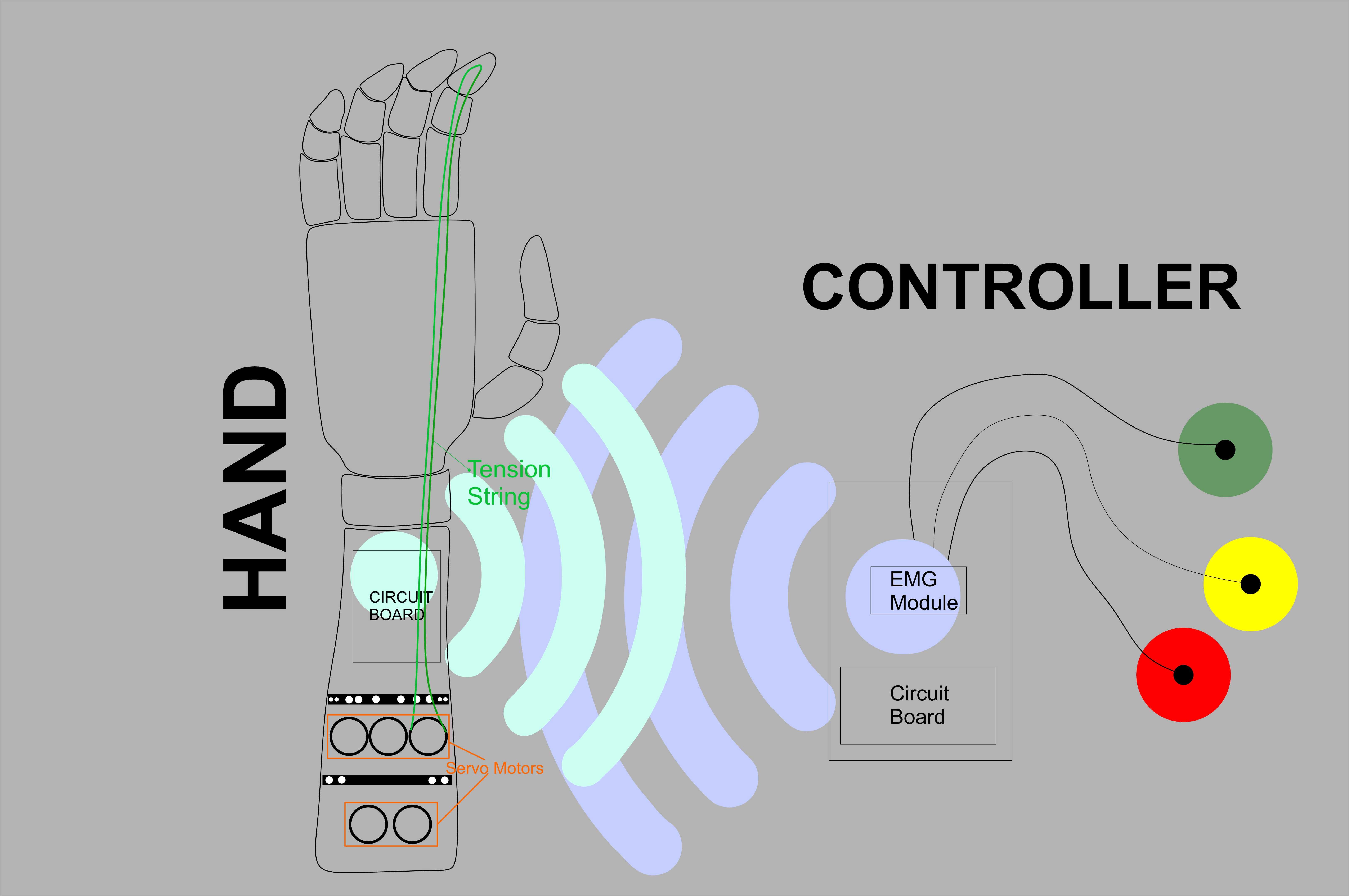
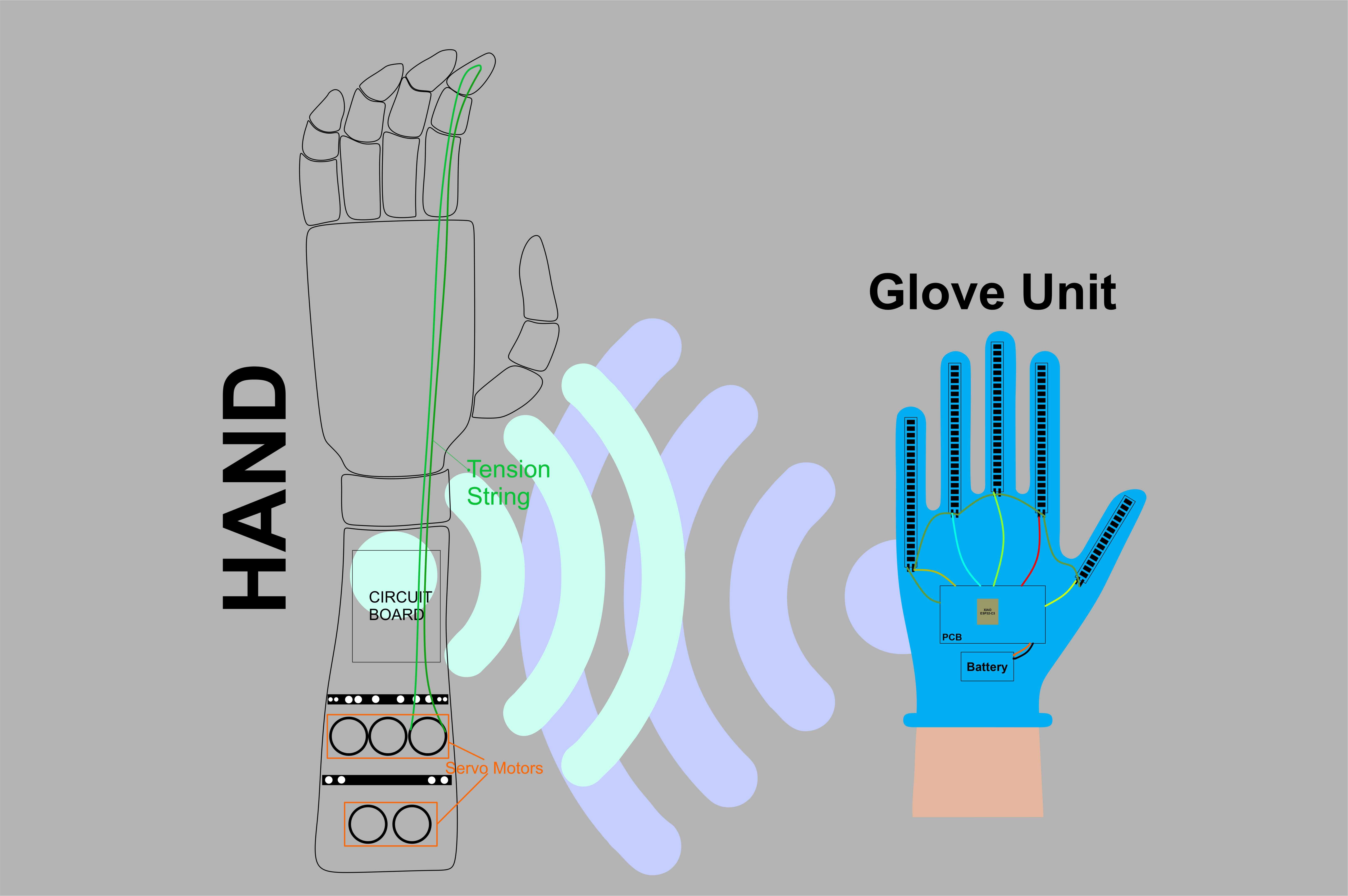
System Block Diagram
Initial Design
Current Design
Mechanical Design
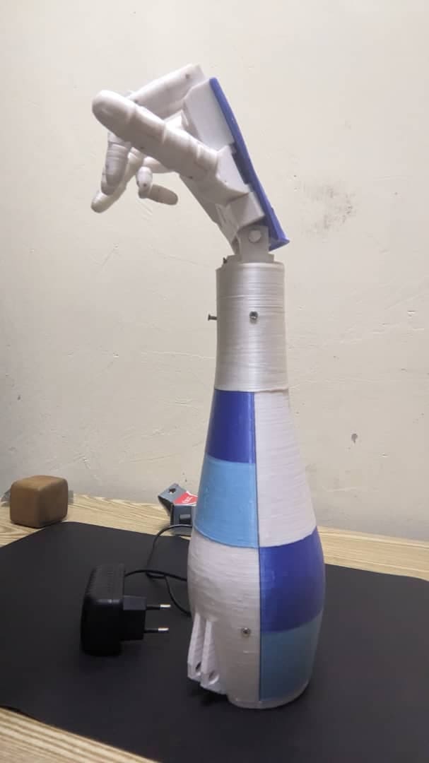
Hand Design
To develop the mechanical structure of the bionic hand, I researched several open-source designs. I selected the InMoov robotic hand model as the base, which I then customized to integrate my own servo and wiring layout.
- Each finger is attached to a servo motor using fishing line to mimic tendon behavior for opening and closing.
- The mechanical hand is 3D printed using PLA and assembled using bolts for strength and modularity.
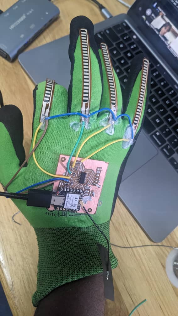
Glove Design
The glove was made using two layers: the inner glove that holds five flexible resistors (one for each finger) connected to a custom PCB and the outer glove that covers and protects the sensors and board for better durability and maintenance.
Electronics Integration
Hand Unit
Microcontroller: ESP32-S receives wireless commands
Actuators: 5 servo motors, one for each finger
Mechanism: Fishing line tightens or loosens to open/close fingers
Power Supply: 5V adapter for servos, with 3.3V regulator for the ESP32
PCB: Custom-designed for servo headers, power regulation, and signal routing
Initial Plan with EMG Sensors
- One microcontroller was connected to EMG electrodes, meant to read muscle signals.
- These signals would be transmitted wirelessly to the second microcontroller on the hand using ESP WiFi.
- The receiving controller would control each finger based on the interpreted gesture.
Updated Plan with Flexible Resistors (Glove unit)
Due to the EMG failure, I redesigned the sensing system using flexible resistors, one per finger.
- These resistors change resistance based on finger bending.
- They are connected to analog pins of the microcontroller(Xiao ESP32-3C) in the glove unit.
- Data is sent wirelessly to the hand unit, which actuates the servos accordingly.
Power Management
Hand Unit
Powered by a 5V power adapter to supply sufficient current to all five servo motors with a
voltage regulator on the PCB which steps down voltage to 3.3V for the microcontroller.
I also include capacitors in the circuit board to add smooth power surges when servos move simultaneously
Glove Unit
Powered by a 3.7V Li-ion rechargeable battery with regulator is used to safely step the voltage down to 3.3V.
Testing
First Test - Servo Movement
I tested each servo motor independently after connecting them to the fingers using fishing lines. Using simple servo code, I ensured that each finger could fully open and close, verifying that the mechanical linkages and electrical signals worked as expected.
Second Test - Wirelsess Connection
On the second test, I verified wireless communication between the glove and hand microcontrollers using the ESP-NOW protocol. I implemented basic commands such as OPEN and CLOSE to confirm connectivity. When I sent the OPEN command, all fingers extended; when I sent CLOSE, the fingers curled in. This confirmed successful bidirectional communication.
Third Test - Full Integration
Finally, I tested the full integration by wearing the glove. As I flexed my fingers, the flexible resistors detected the motion and
wirelessly transmitted corresponding commands to the hand unit. The bionic hand responded in real time, mimicking the same movements.
This real-world test validated the complete system and its responsiveness.
I keep on adjusting the flexible resistor codes to much the fingers movement perfectly.
Cable Management
The cables in the hand unit are passing under the servo motor holder to the pcb pins and the pcb is well mounted in the hand under the tension fishing line. The power cable runs from the pcb to the outside where you plug it into socket to power the hand unit.
Maintenance
The bionic hand can be opened by removing bolts on the casing, giving access to the servo, pcb and the wiring
The glove is also maintainable:
- Flexible resistors can be swapped easily
- Outer glove protects inner wiring
- Connectors are detachable for easy charging or debugging
Files
3D Hand Design: STL files
Hand PCB: KiCad Design
Glove PCB: KiCad Design
Hand codes: Arduino Codes
Glove codes: Arduino Sketch