Week 2 - Computer-Aided Design
Assignment
Model (raster, vector, 2D, 3D, render, animate, simulate, ...) a possible final project, compress your images and videos, and post a description with your design files on your class page
Raster
GIMP
GIMP is a free and open-source raster graphics editor that is widely used for tasks such as photo editing, graphic design, illustration, and digital painting.
Software DownloadGIMP
Getting Started
"I began by downloading and installing GIMP, which was pretty straightforward. After the installation, I opened the program, then clicked File and selected New to create a new project."

After creating a new project, I set the measurement unit and adjusted the size of the working area (artboard). I chose a canvas size of 1200px by 800px.

Next, I used the Gradient Tool to create a sunset effect. I painted the ground with a gradient, blending white and reddish colors to resemble the warm hues of a sunset.

After applying the gradient fill, I selected the Brush Tool, set the color to black, and began drawing a road on the canvas.

Still using the Brush Tool, I added the road barriers by drawing straight brush strokes along the edges of the road.


Using the Ellipse Tool, I drew a circle to represent the sun. Then, I right-clicked and selected Edit > Fill to fill the circle with color


Continuing with the Brush Tool in GIMP, I drew two black beach trees on the canvas

TO save you can press ctrl+s but I clicked file > save >choose location to save in

Gave the project a name then click save

GIMP Design fileDownload
Vector
-
CorelDraw
CorelDraw is a vector graphics design software used for creating logos, illustrations, layouts, and technical drawings.
Logo Design
From CorelDraw, I designed a logo by combining my name initials (Letter J and B)
I opened coreldraw from my pc
Download:CorelDraw
From the home screen on the Get Started tab, you can choose to use a new document or templates.
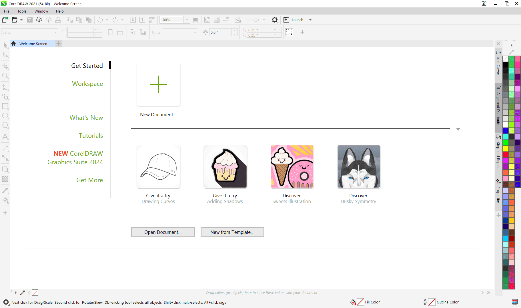
Photo: CorelDraw Homepage I created a new document with custom size of 60*30 cm
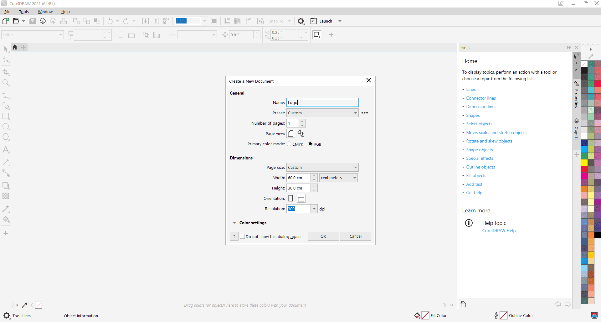
Photo: Creating a new document The CorelDraw interface has several parts:
Menu bar: give me access to a variety of tools and settings, like saving files, editing objects, adjusting settings, and more.
Property Bar: displays context sensitive options for the selected tool or object.
Tool Bar: contains all the drawing and editing tools I will use to create and manipulate vector graphics such as shape, pick, ..
Dockers panels that provide additional features and tools such as join curves, align and distribute, ...
Drawing Area: is where I do all of my work.
Color Palette: is where I select and apply colors to my object.
Status bar: it provides information such as the current zoom level, cursor position, and active tool.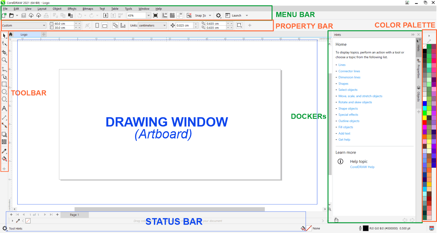
Photo: User Interface I started my design by adding text of my name initilas, J and B using text tool.
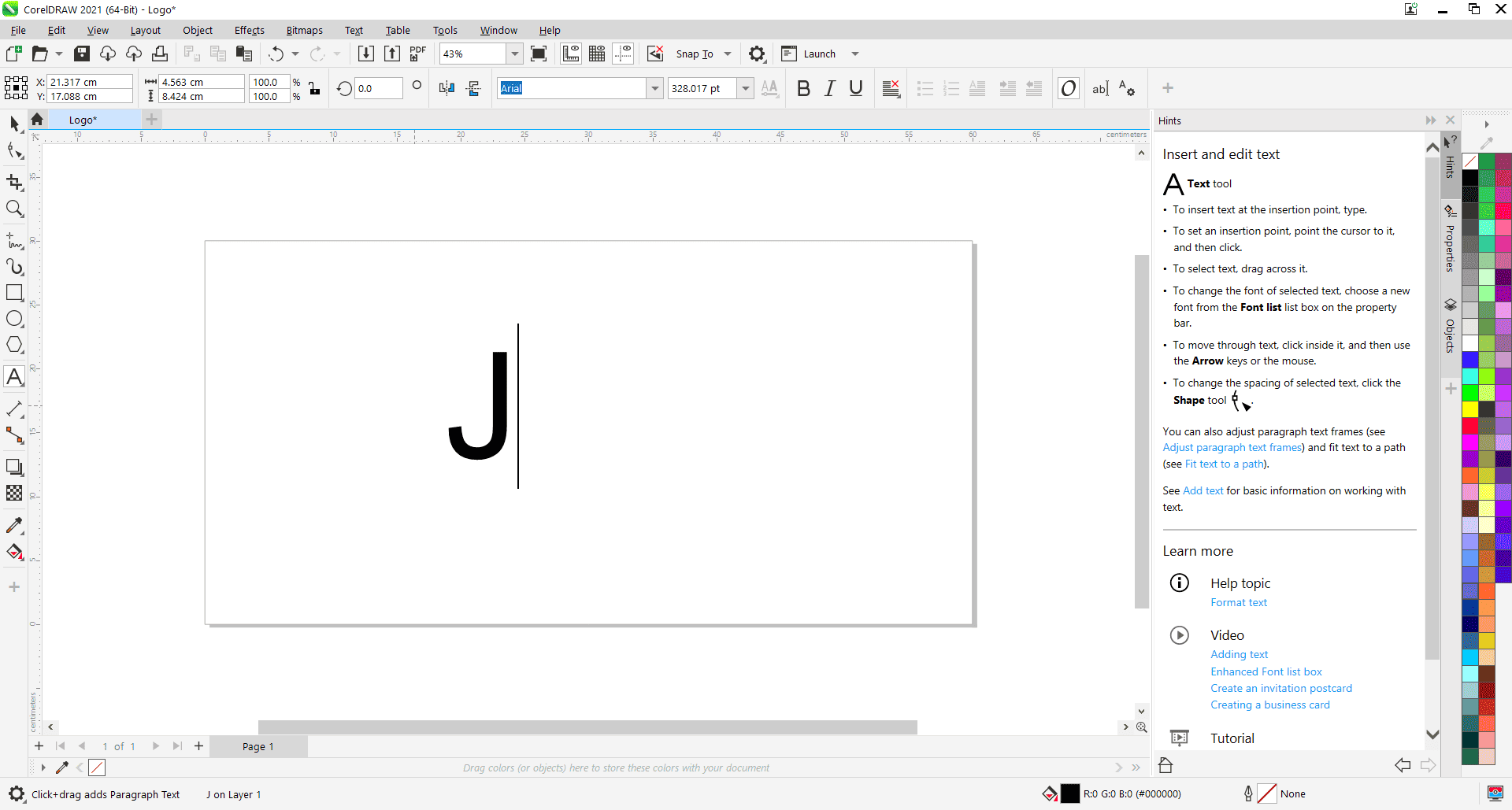
Photo: Inserting Text Changed the font of J to Ananda Black
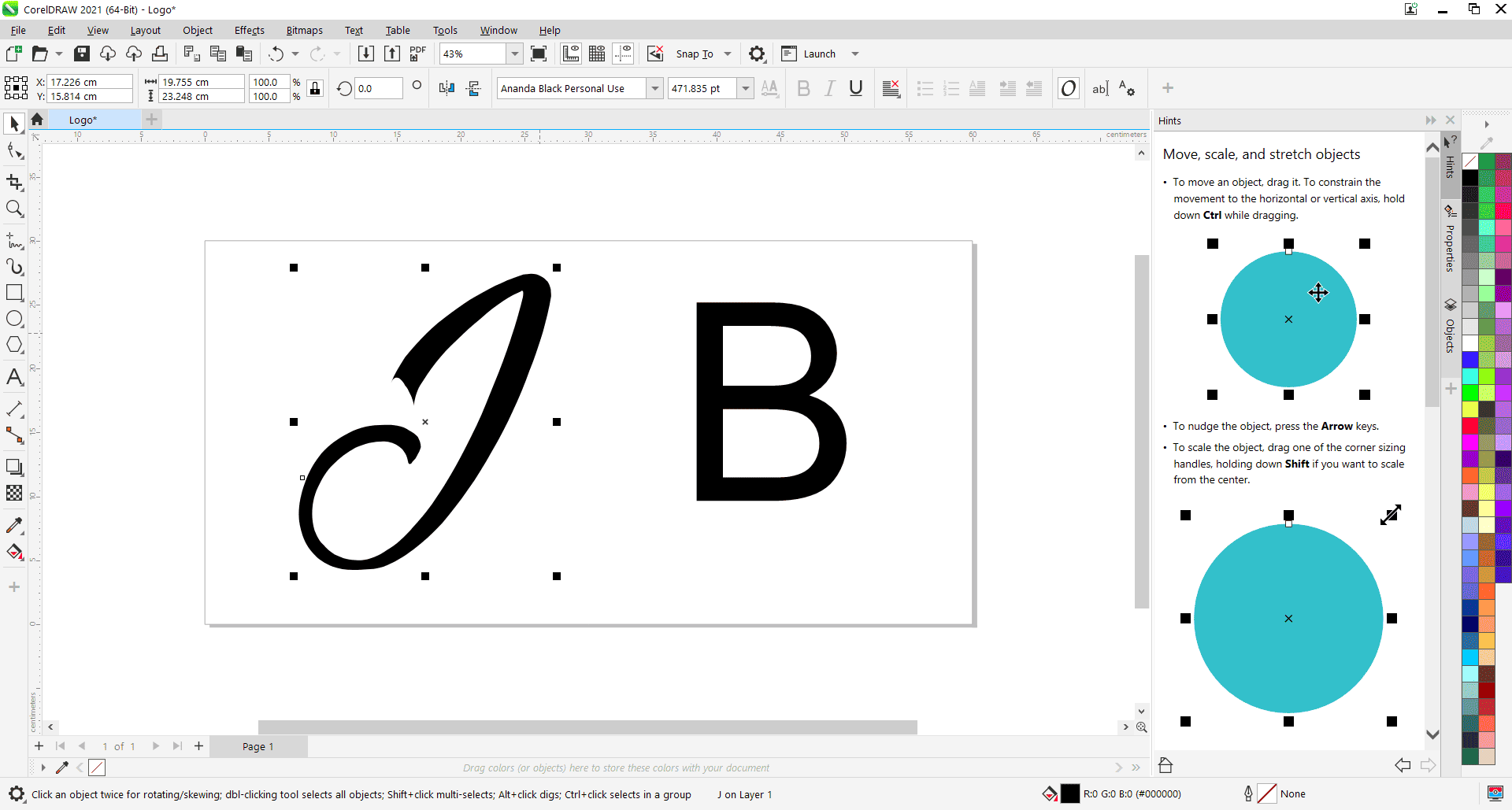
Photo: Changing Font I selected my letters, right-clicked and chose Convert to Curves, then brought the letters together to create a single combined shape.
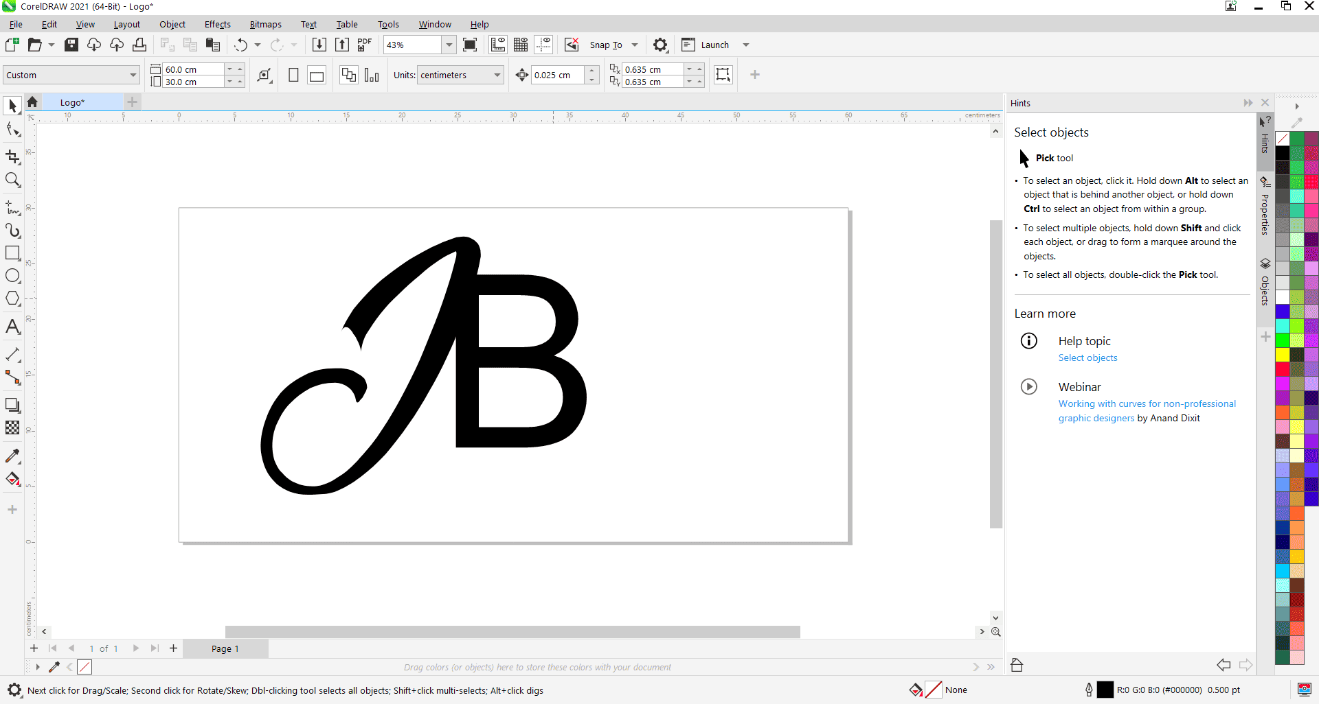
Photo: Converting to Curves Next, I removed the color, set the outline to hairline, and used the Virtual Segment Delete tool to trim the intersecting lines.
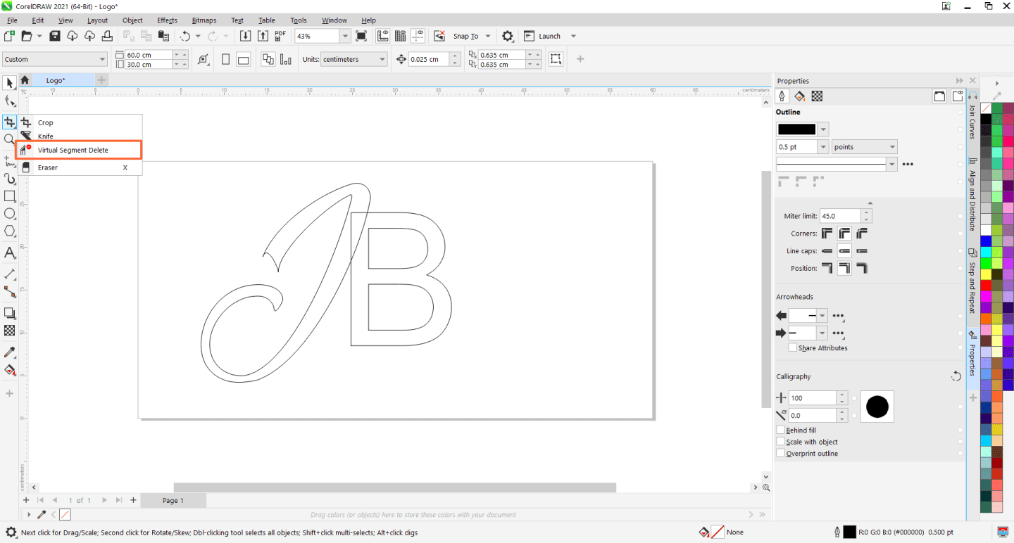
Photo: Trimming Since the letters were two separate objects, I selected them both, combined them, and then used the Join Curves option in the docker to join their nodes, creating a fully closed shape.
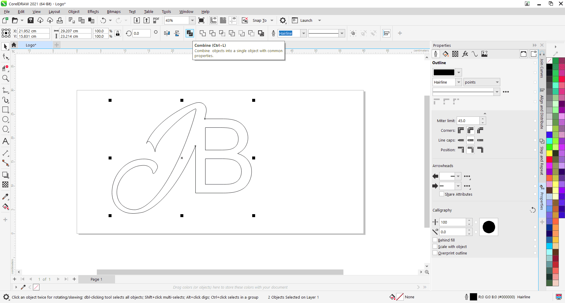
Photo: Combining curves I then filled the shape with black and began experimenting with different shapes, starting with the rectangle and circle tools, to design medals with the logo in the center. To create a perfect circle, I held down the Ctrl key while drawing.
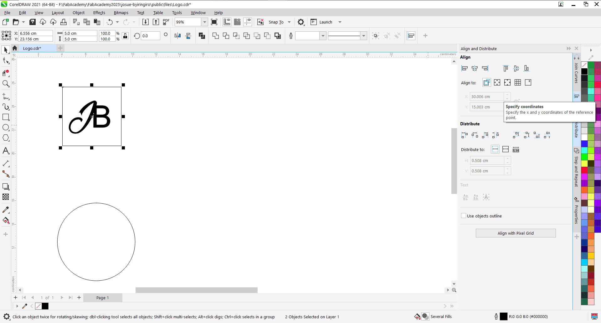
Photo: Rectangle shape Next, I focused on aligning the logo in the center. I selected both the logo and the rectangle, then went to the Align and Distribute tab in the docker. I chose both the vertical and horizontal center alignment options. To check the alignment, I looked at where the blue line appeared. It's important to note that alignment happens based on your selection, the page, or the position you choose.
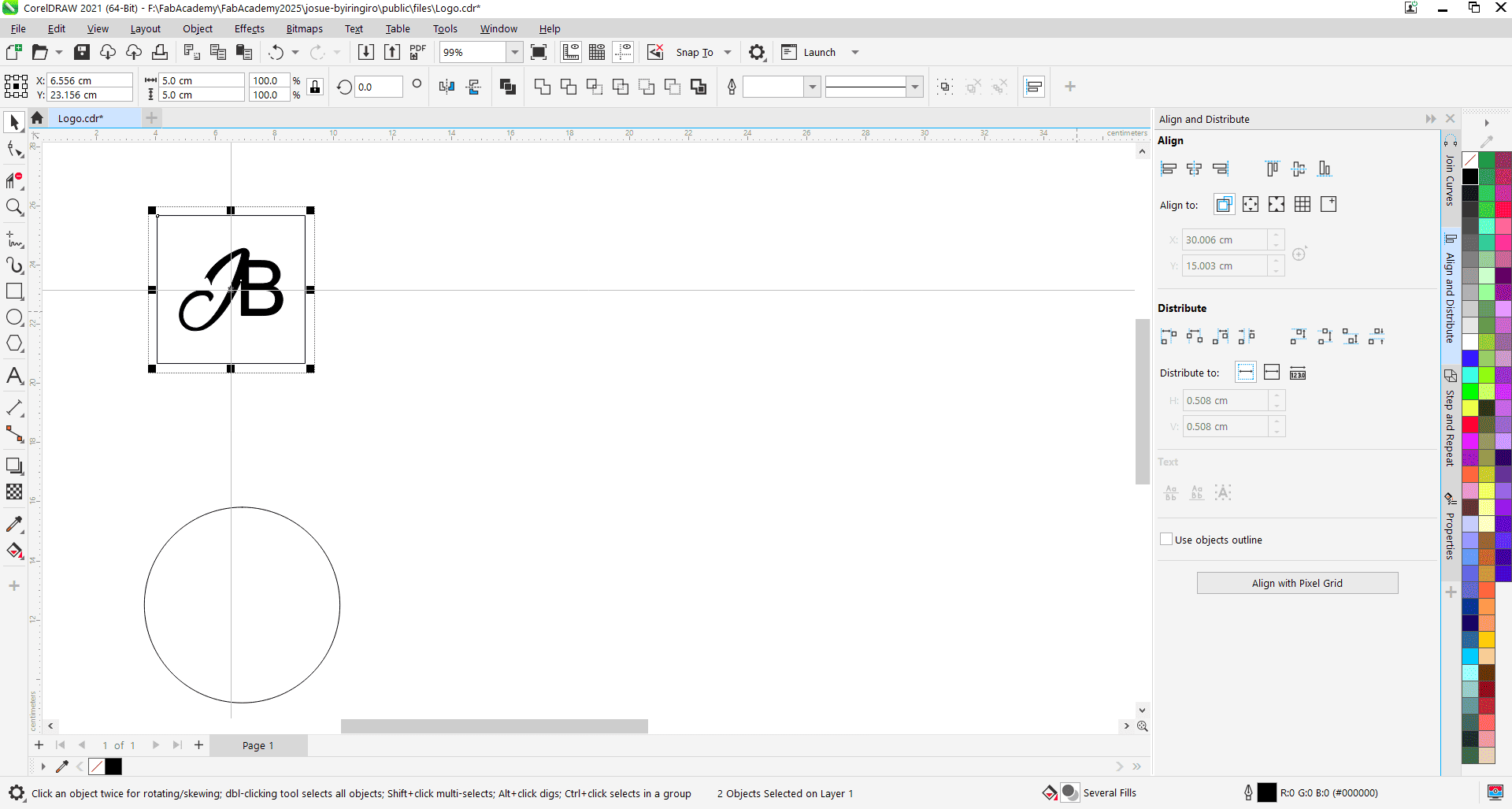
Photo: Alignment I continued experimenting with the stroke, increasing its size and changing the colors from the color palette to find better matching color combinations.
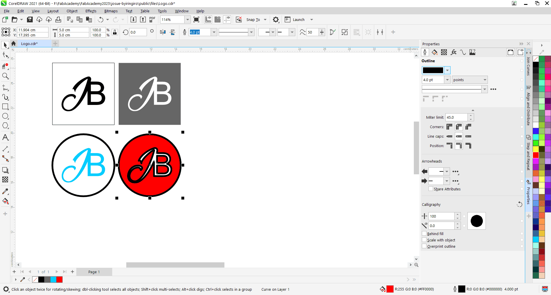
Photo: More shapes 
Photo: Changing colors Next, I explored more shapes and selected the Polygon tool. With the Polygon tool, you draw the shape, and then at the top, you can enter the number of sides you want for the polygon.

Photo: Polygons I kept experimenting with different numbers of sides for the polygon, adjusting to see how each variation changed the overall design.

Photo: Bspline Tool I also used the B-Spline tool to draw an irregular shape for the medal. Alternatively, you can use the Pen tool to create custom shapes as well.

Photo: Drawing with Bspline tool 
Photo: Created medals Design File: Coreldraw
Adobe Illustrator
Image link:Coffee Bean
3D Designing
SolidWorks
SolidWorks is a 3D CAD software used for designing, modeling, and simulating parts and assemblies in engineering and manufacturing, which helps create detailed product designs and test their functionality before production.
I used SolidWorks to design a living room table and rendered it to visualize the material and appearance I applied.
Getting Started
I opened SolidWorks and selected the part document since I was starting the sketch from scratch.
SolidWorks Software: Download
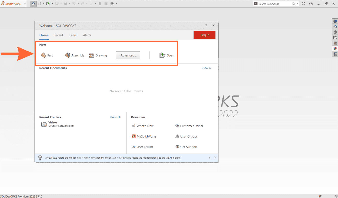
I then selected the right plane to begin drawing, as I was designing the table from the side.
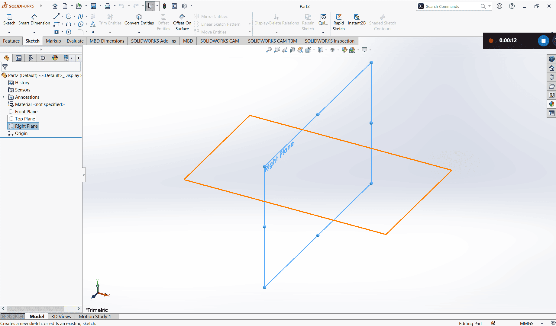
From the Sketch tab, I selected the line tool and drew the table's outline, then converted it into construction lines.
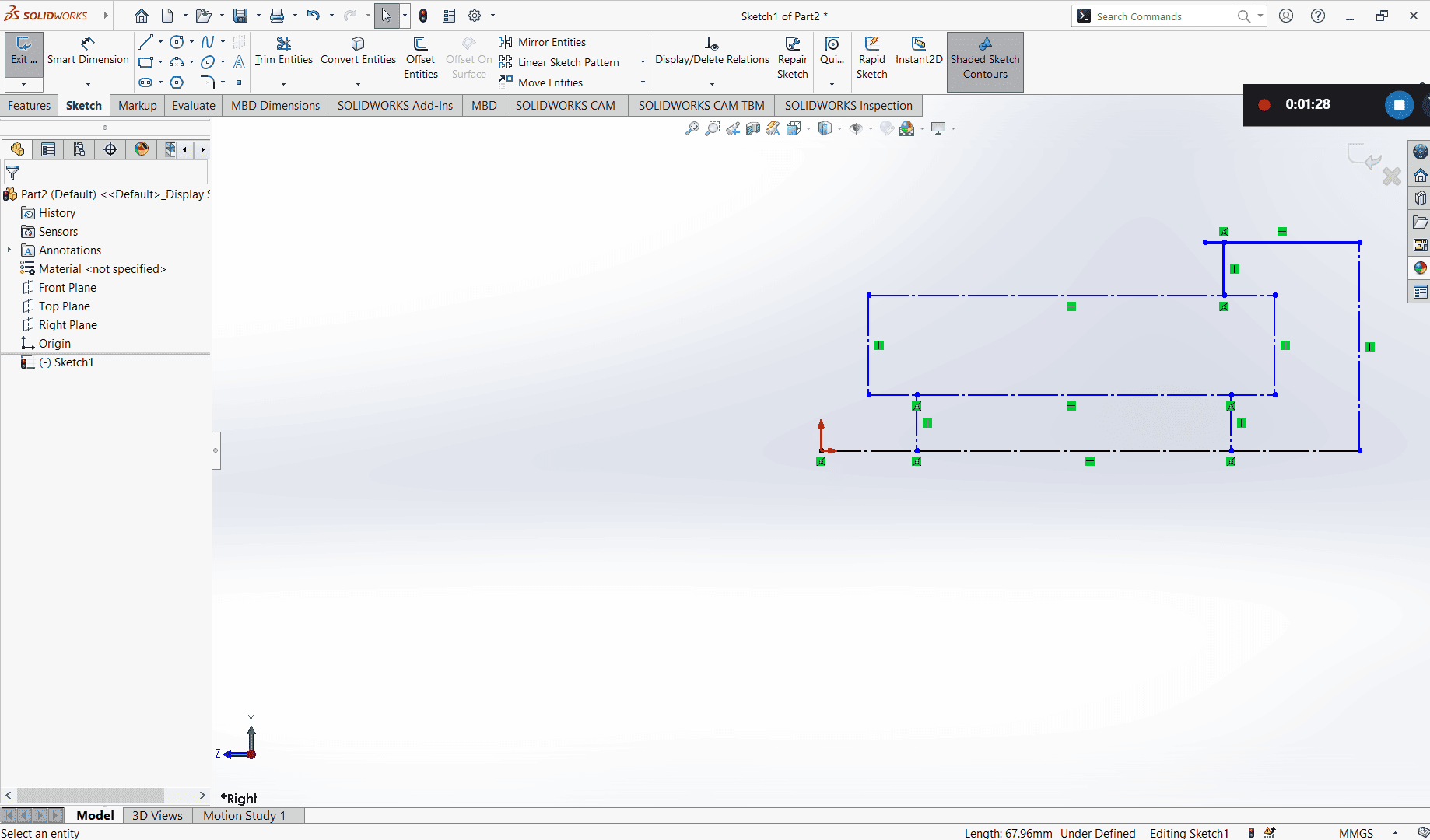
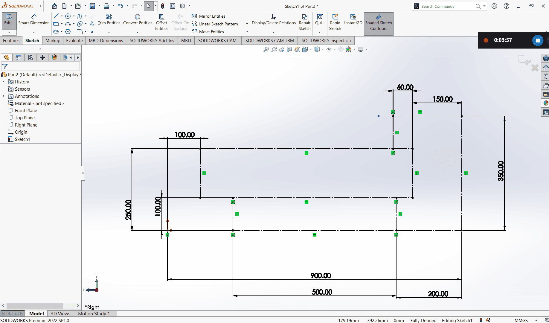
Again, from the Sketch tab, I used the Smart Dimension tool to add the correct measurements to my table.
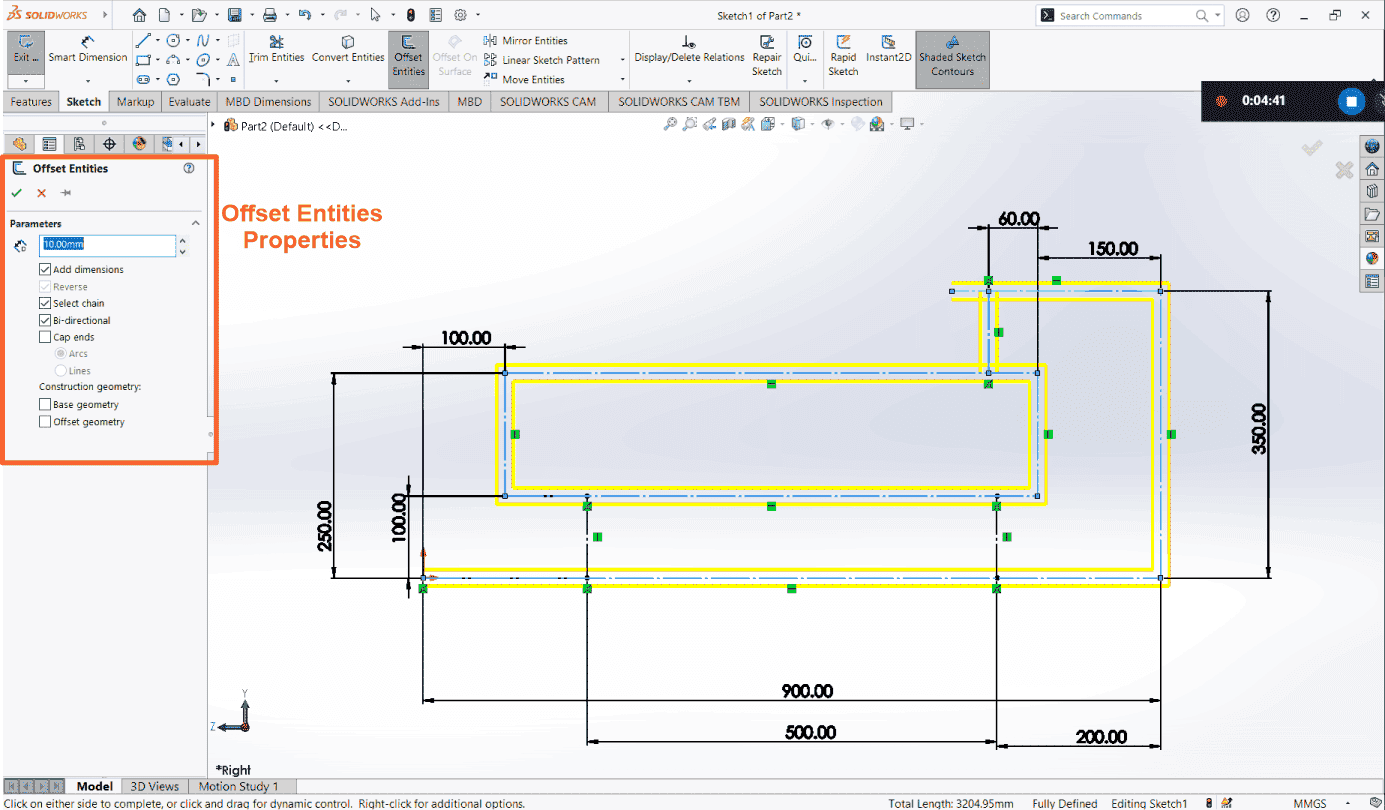
To create the thickness of my table, I used the Offset Entity tool. I selected my lines, set the offset distance to 10mm, and checked the bidirectional option, which allowed me to create lines on both sides of the construction line.
I then selected the line tool again to connect the open lines created by the Offset Entity, forming a fully closed shape.
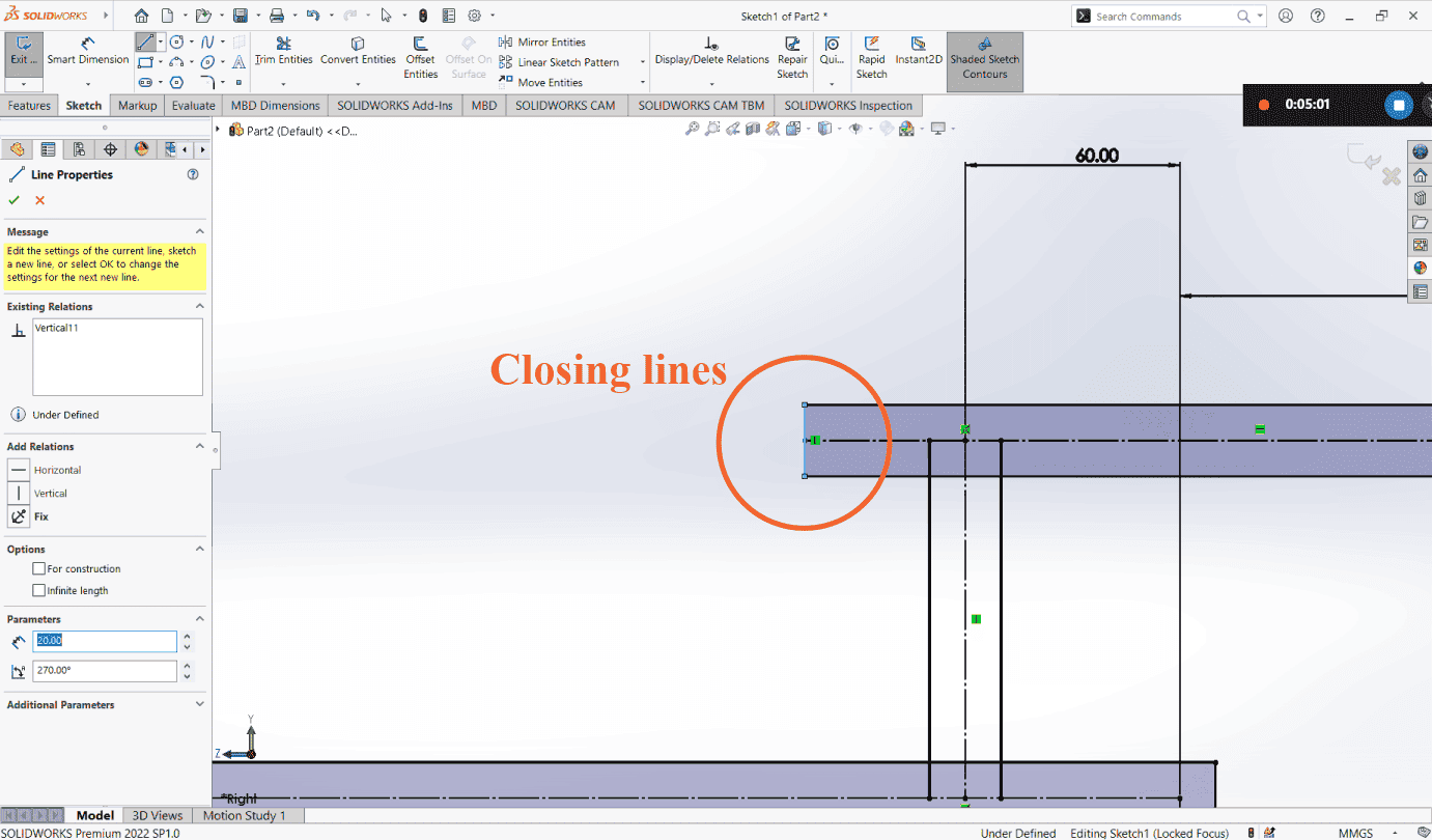
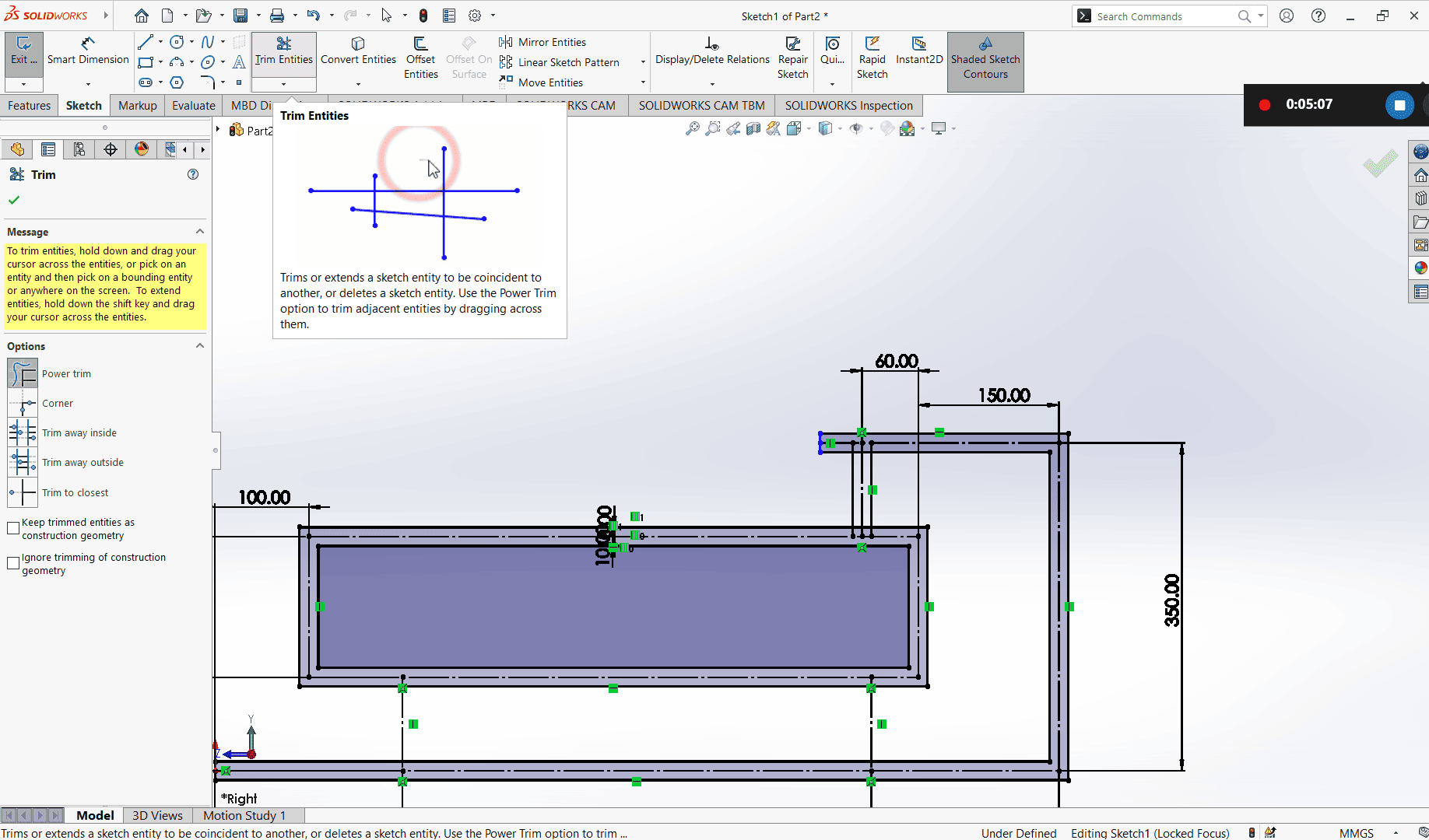
Since there were some unnecessary lines, I used the Trim tool to remove them, resulting in a cleaner shape.
I especially like using Power Trim because it makes the process easier, I simply move the mouse cursor, and
every line I cross gets trimmed.
The other trimming options include trim to Closest, trim away inside, trim away outside, corner
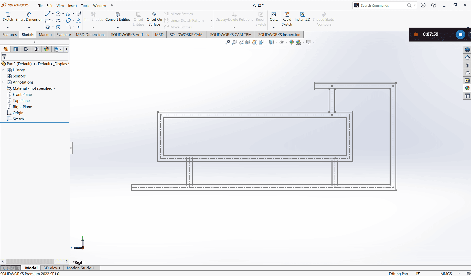
After trimming, I clicked Exit Sketch, and at that point, my design was fully defined.
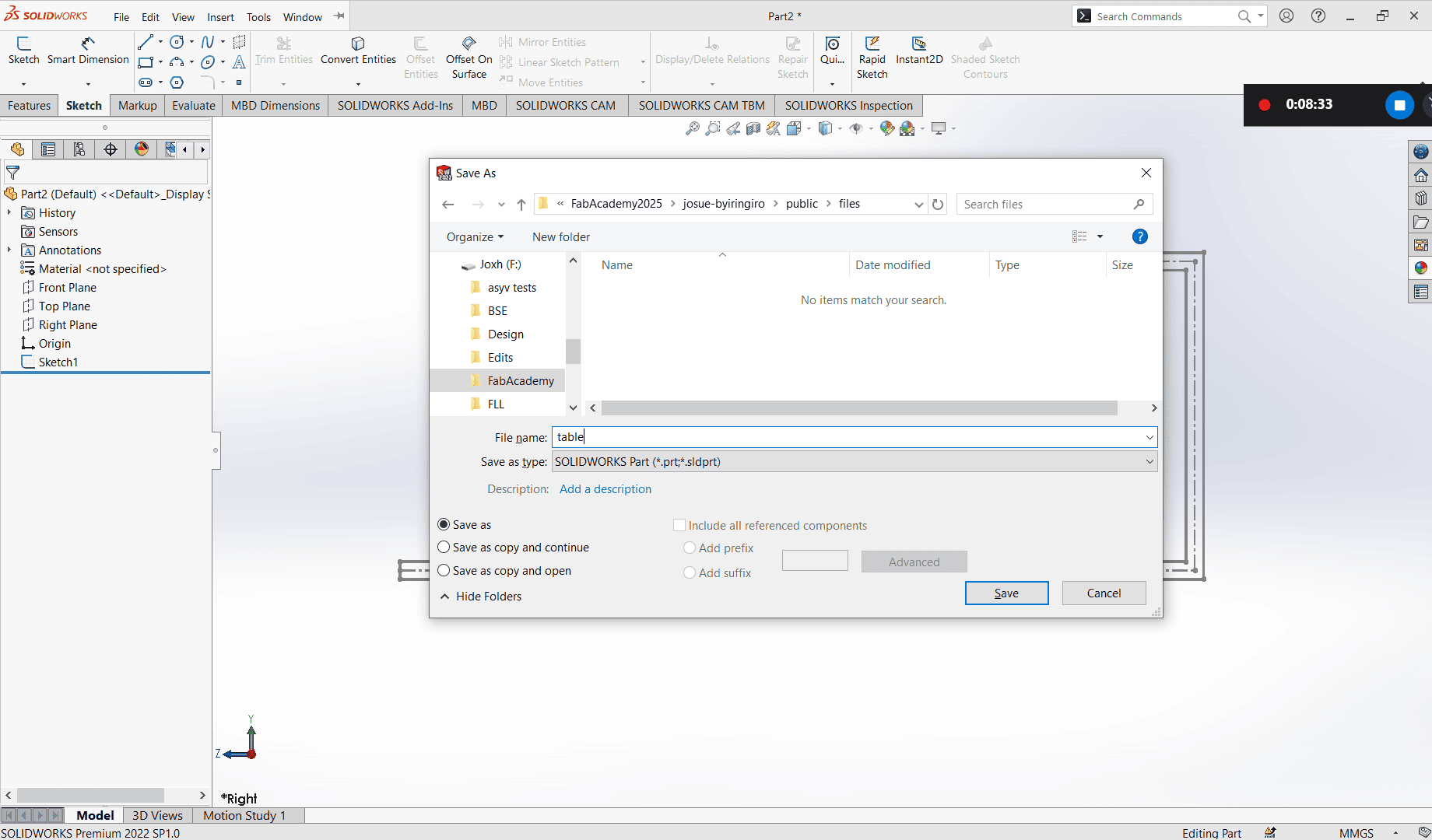
Saving
It's always a good idea to save your design before continuing to edit, as it helps prevent losing your work.
To save, I simply press Ctrl+S, navigated to the desired location, enter the project name "Table,"
and then save. After that, I continued editing.
(you can also press the file button on the top > save > location > name > save)
After saving, I continued editing my table. I selected my sketch, moved to the Features tab, and chose Extrude Boss/Base. In the Extrude Boss/Base options, I set the direction to Mid Plane, allowing the extrusion to go in both directions and keeping my sketch centered. This was important since the features of my table aren’t all on the same level. I also used Selected Contours to extrude each region independently.
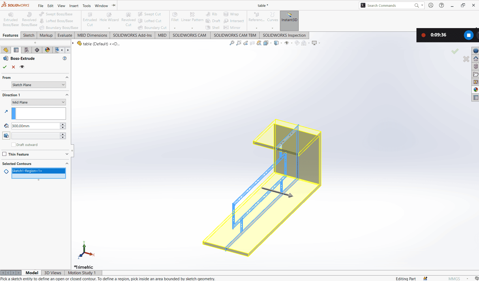
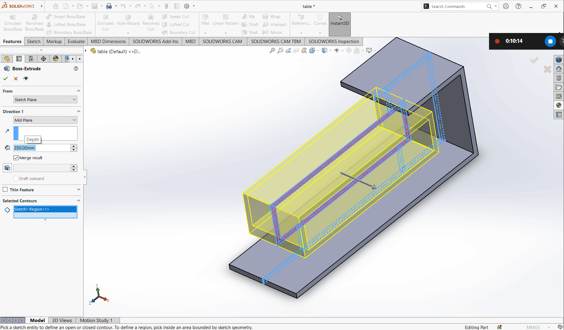
After extruding the outer part to 300mm, I went back and selected the same sketch for Extrude Boss/Base again. This time, I adjusted the size to 250mm and changed the selected contour to choose the inner part for extrusion.
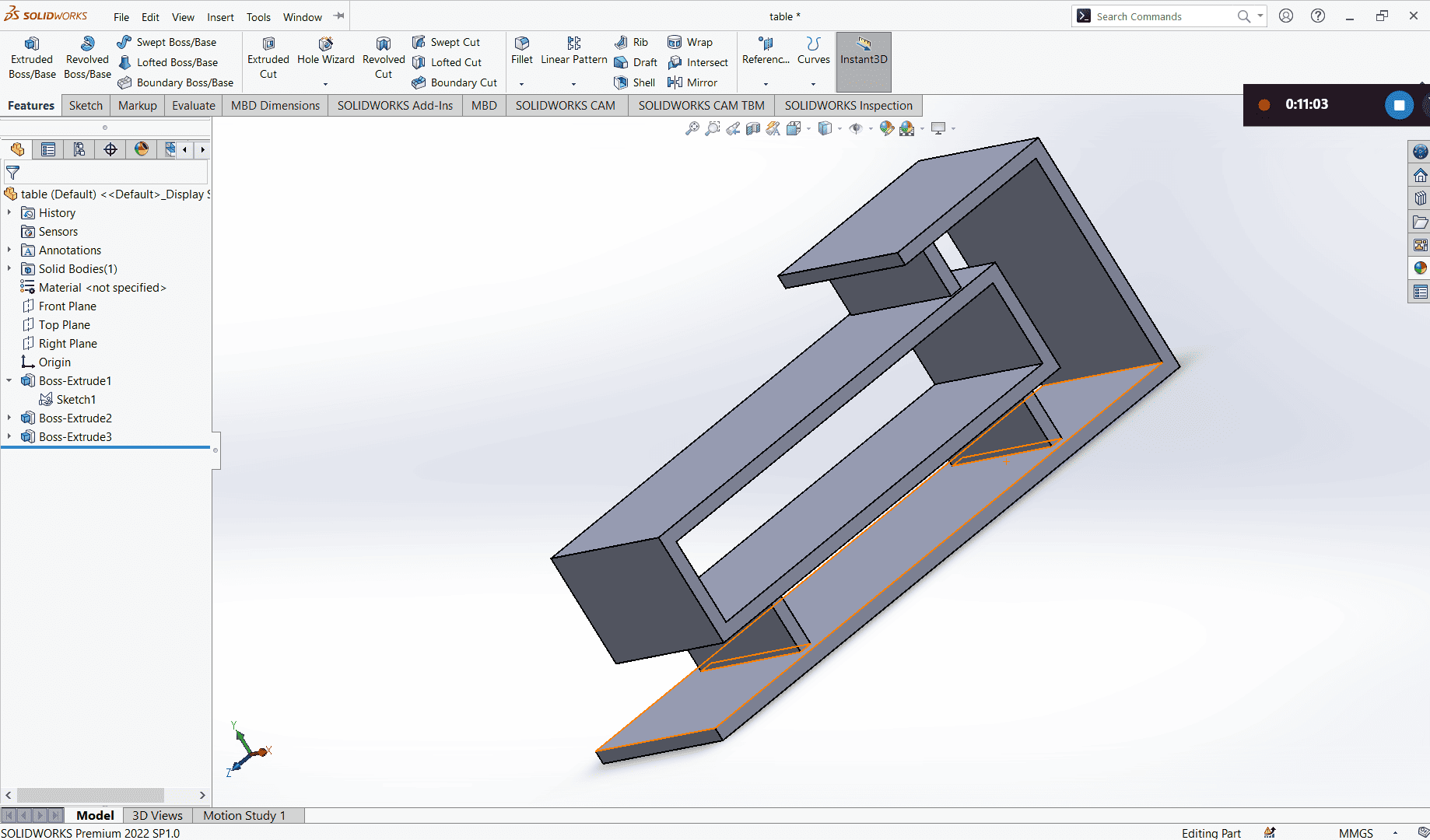
Lastly, I returned to the same sketch, selected the connecting boards as the contours, added the necessary size, and then I was done with extruding.
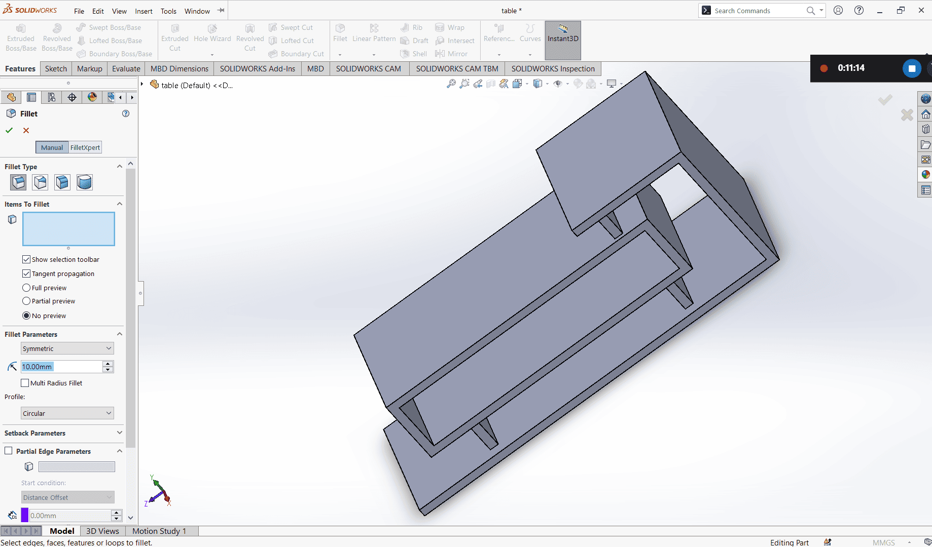
To smooth the edges, I added a 10mm fillet to the selected edges.
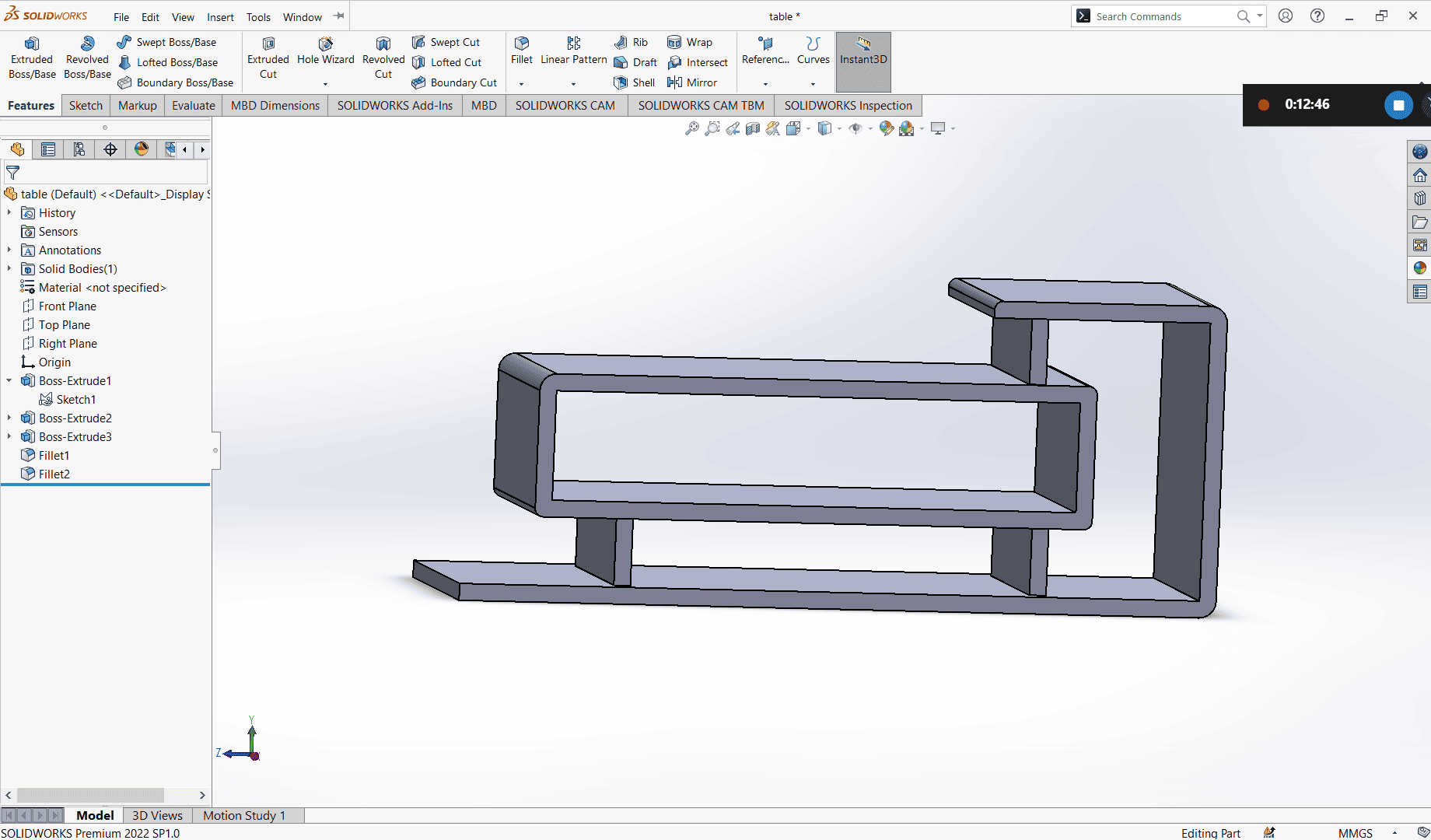
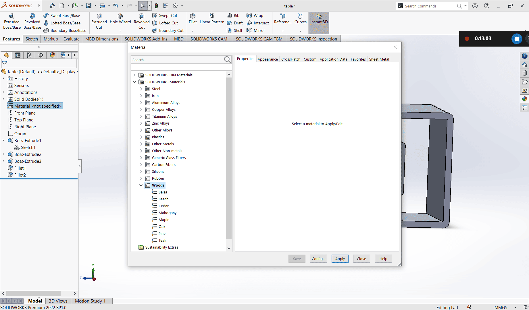
Next, I added material by right-clicking on the Material tab in the left column, selecting Edit Material, then choosing Wood and selecting Maple.
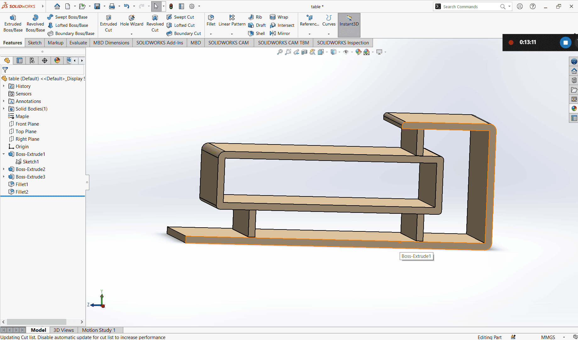
To better see the effect of the wood material, I selected Shaded to hide the lines and get a clearer view of the surface.
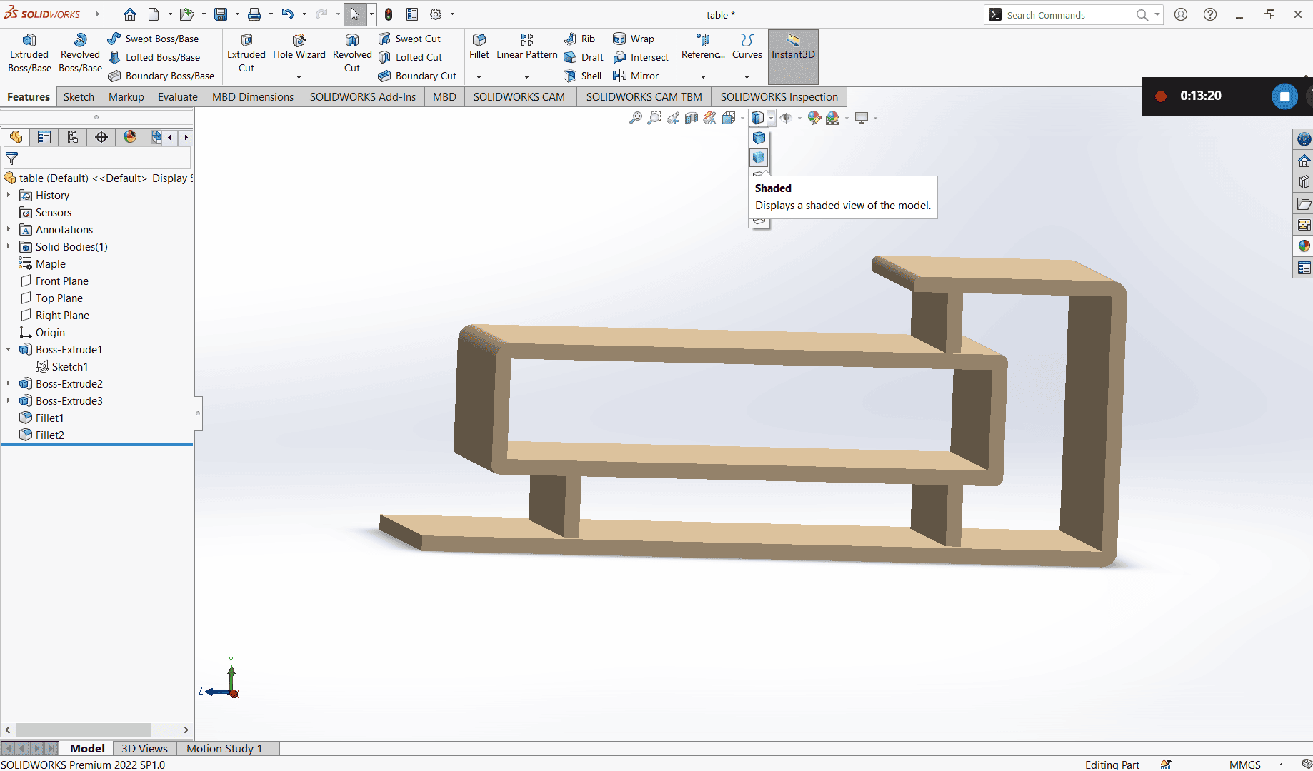
I experimented with different appearances to see which one looked best.
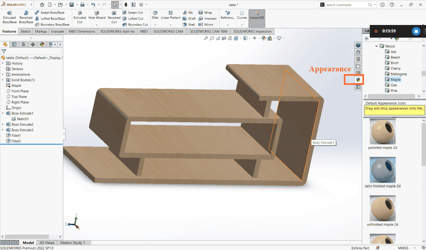
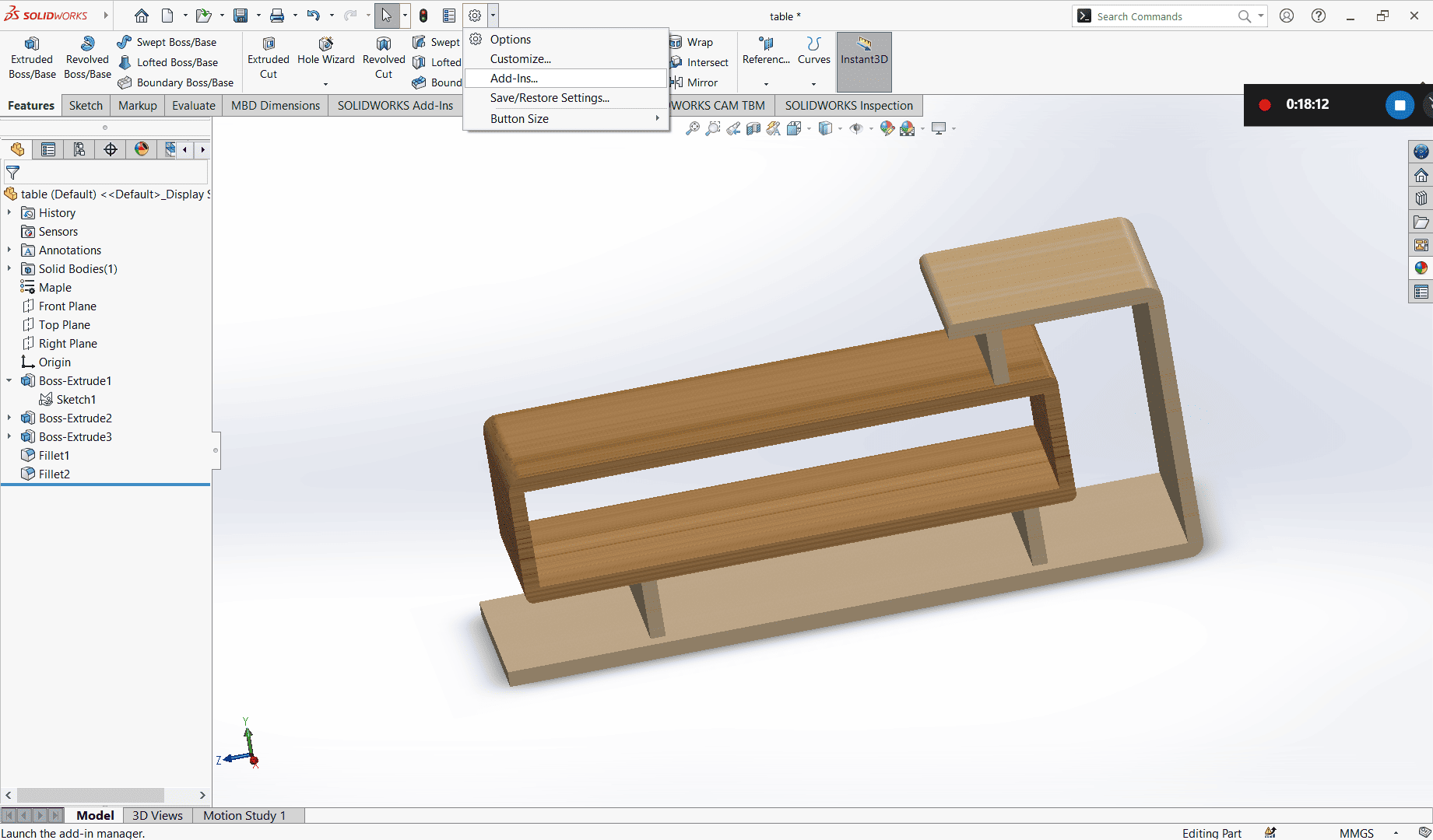
After selecting the appearance, I proceeded to render the image of my table. If the Render Tools tab isnt visible, click Settings, then choose Add-ins, and enable PhotoView 360. This will make the Render Tools tab appear.
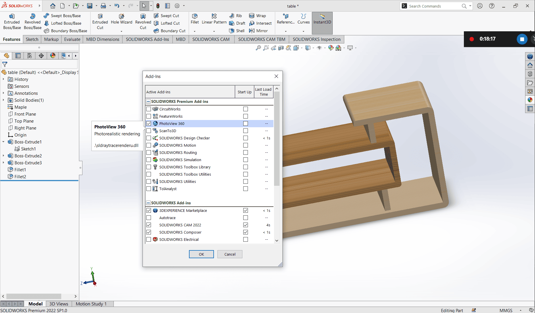
Under the Render Tools tab, I selected Final Render. In the options, I chose to continue without using a camera and perspective, as I had already positioned my table the way I wanted it.
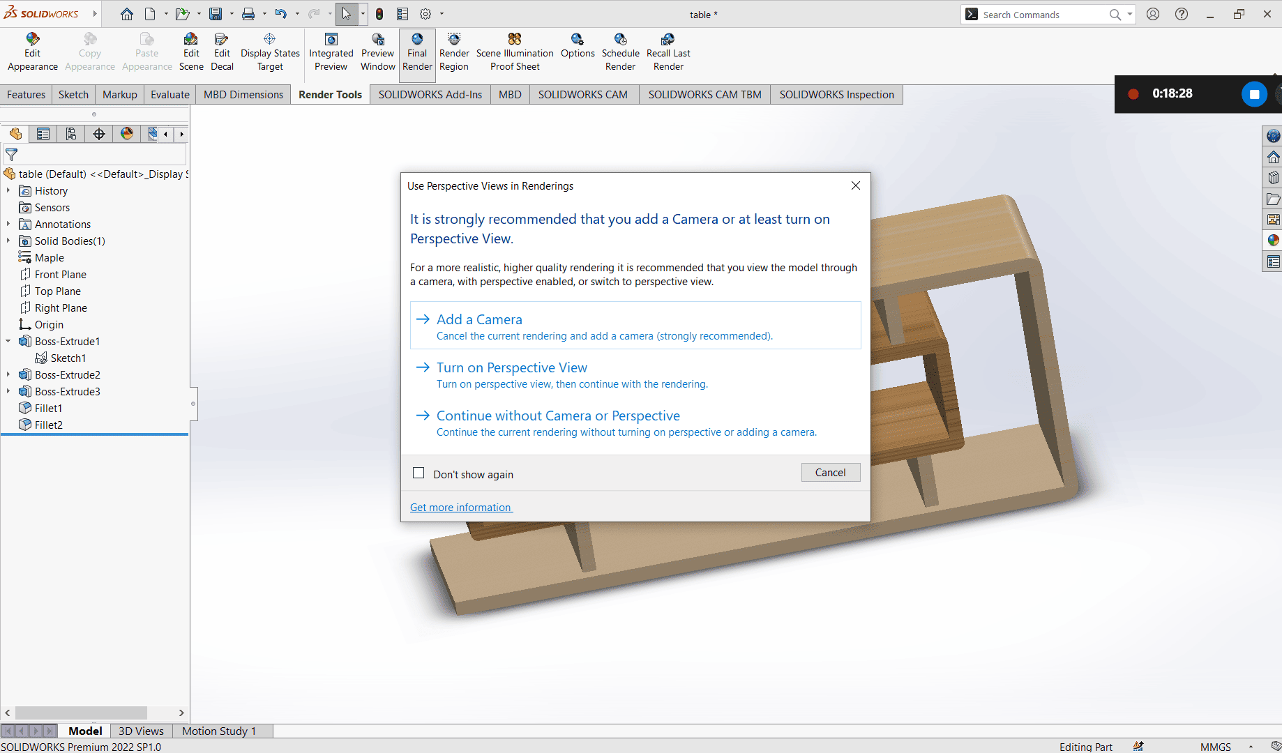
I waited for the rendering popup to finish processing and complete the rendering of my image.
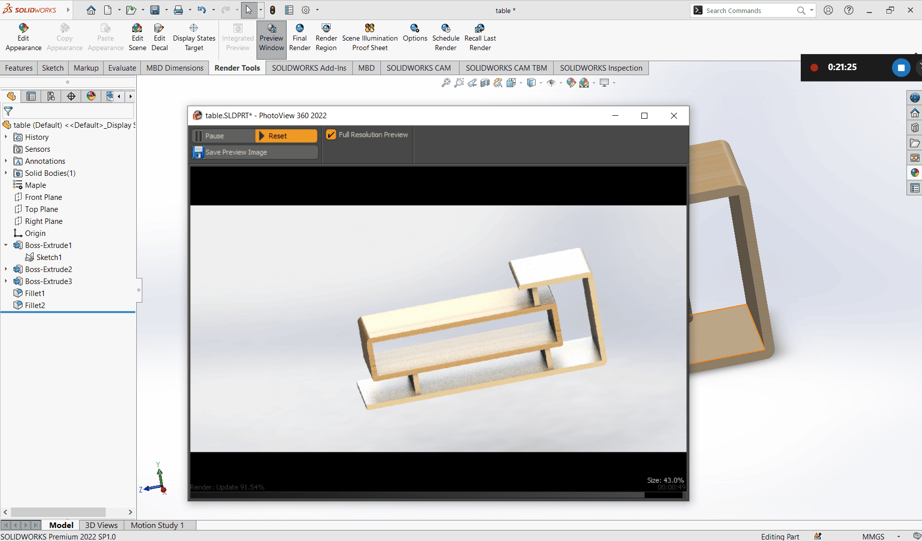
Once the rendering was complete, I clicked Save Image and saved the rendered image to my PC.
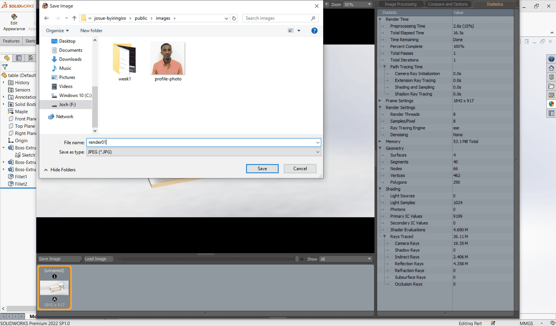
3D Design file: Download
To compress my images I used online website called ILOVEIMG
I uploaded my images and choose compress then downloaded compressed images.