Week 3 - Computer-Controlled Cutting
Assignment
Group assignment:
Do your lab's safety training
Characterize your lasercutter's focus, power, speed, rate, kerf, joint clearance and types.
Document your work to the group work page and reflect on your individual page what you learned.
Individual assignments
Design, lasercut, and document a parametric construction kit, accounting for the lasercutter kerf, which can be assembled in multiple ways.
Cut something on the vinyl cutter.
Summary
This week together with the team we explored the parameters of our laser cutting machine - Full Spectrum Engraver and tested different cuttings.
Personally, I designed a parametric design, cut and assesmbled my pieces. More to that I also explored the features and using vinly cutter - Roland GX-24
where I cut my logo on a stick and mounted it on my laptop.
Laser Cutting
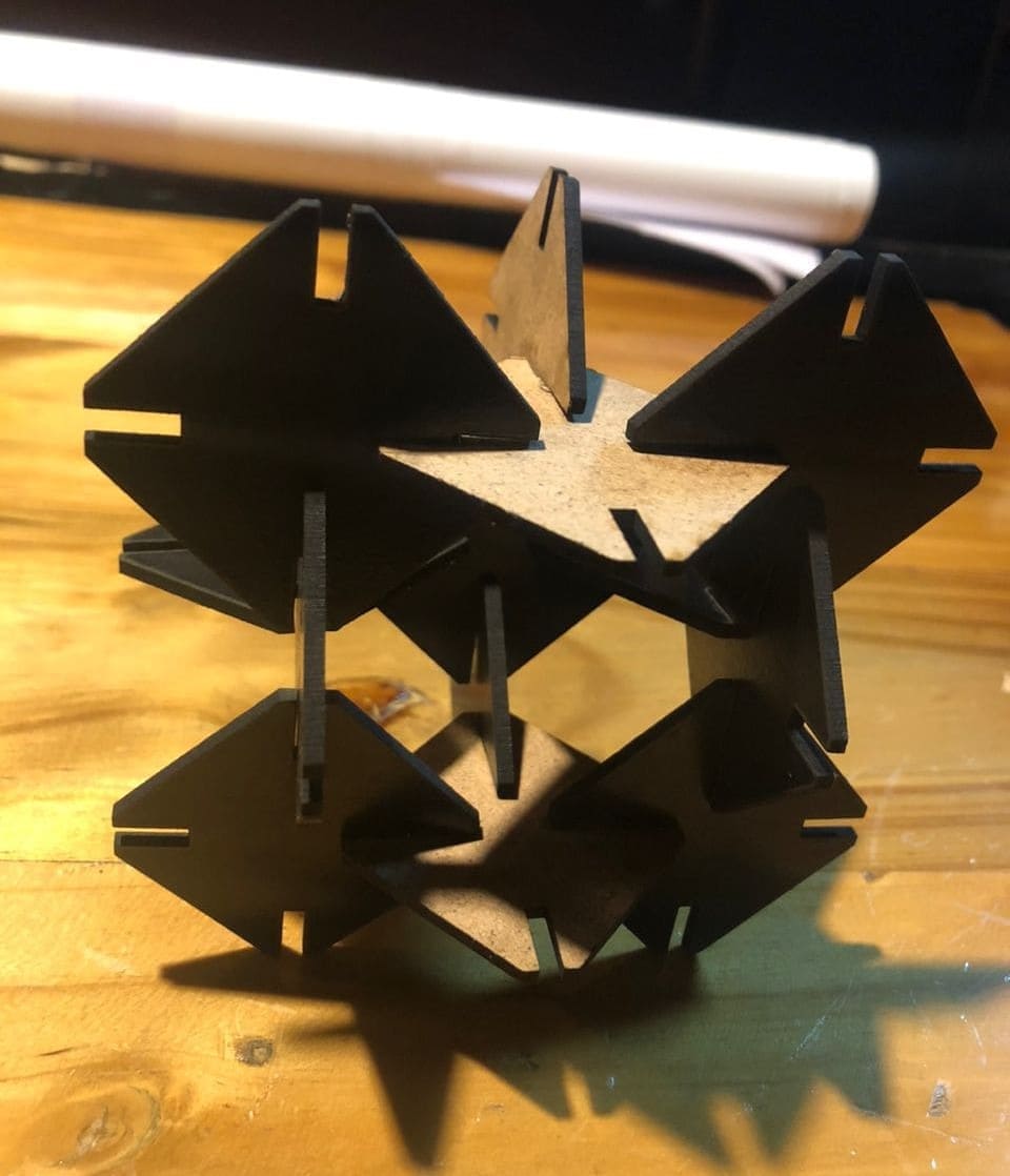
Here is the parametric project I made from small mdf sheets.
How I made it
Design(SolidWorks)
Firstly, I tried to roughly sketch a diamond shape with four gaps which will help to connect it with other similar shapes.
Then I jumped to SolidWorks to design a perfect shape to help me cut it from the laser machine.
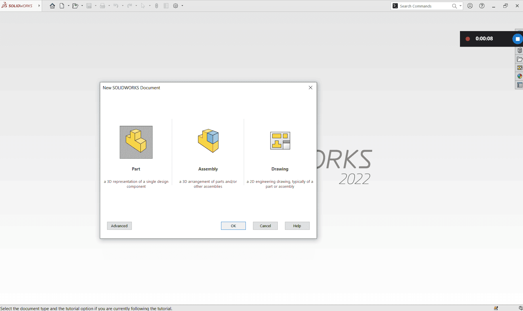
In SolidWorks I started by choosing to Part document > Front Plane > Sketch
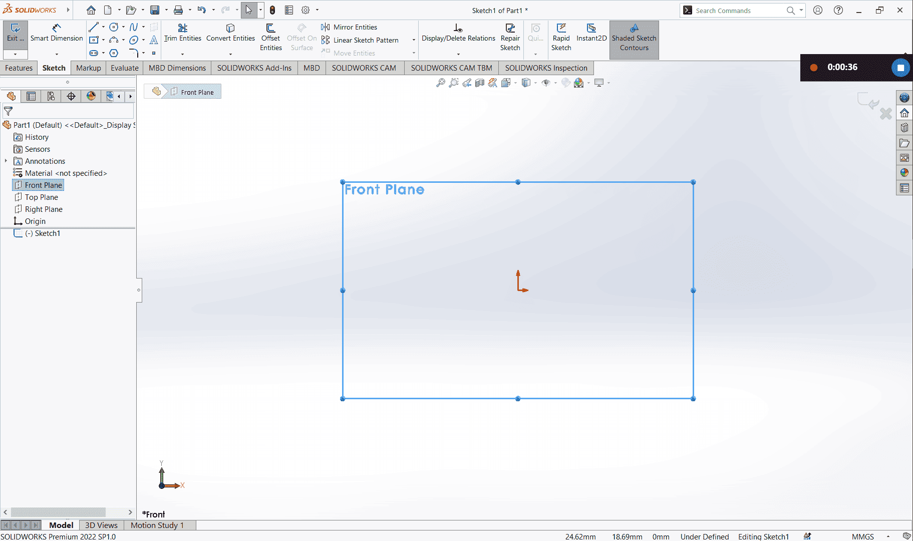
To quickly draw my shape I used to perpendicular center line and sketched a quarter of the diamond shape

Then I added equality property to lines that are similar to keep my sized diamond and measurement. And I moved to equations tab to set my global variable measurements.
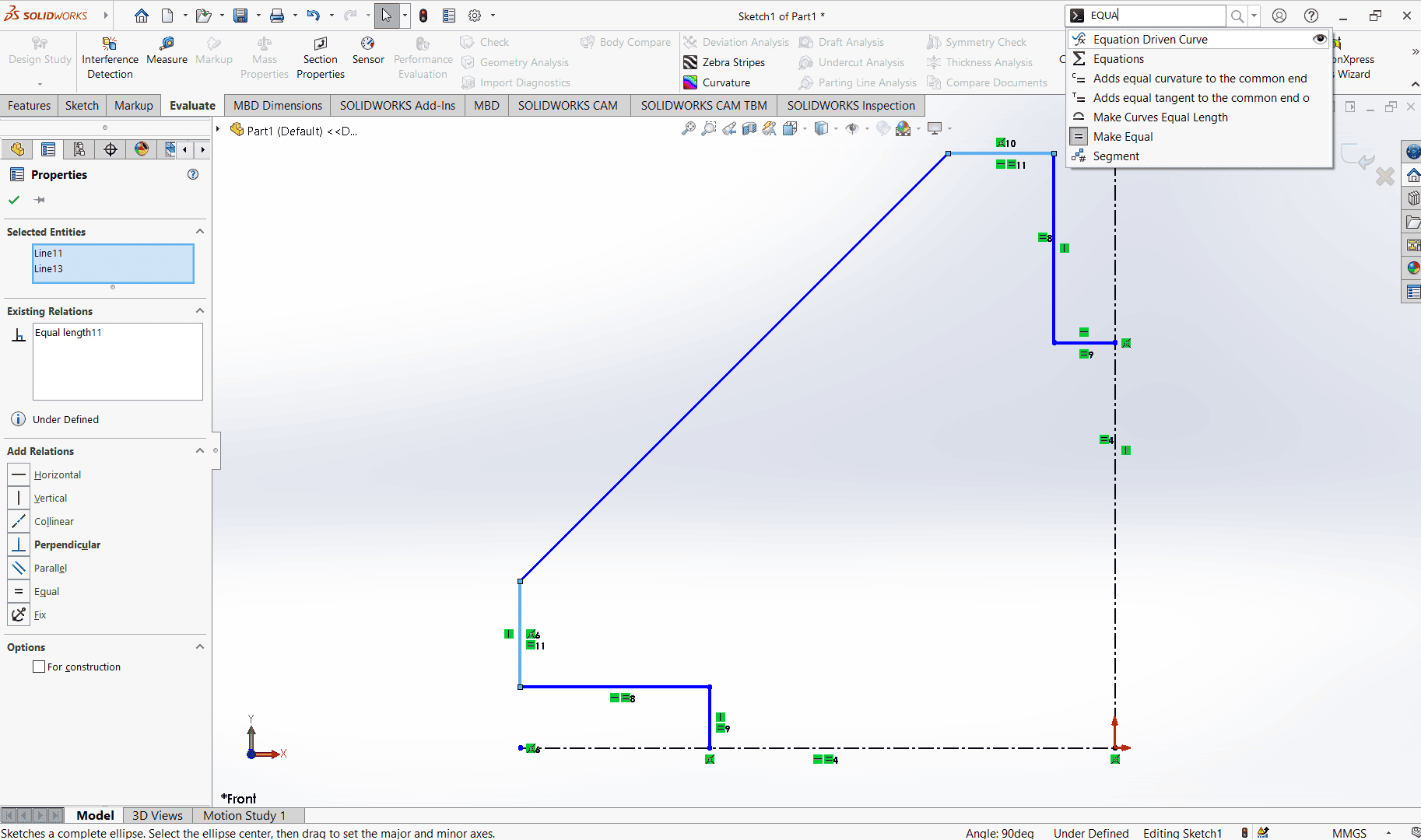
Under the equations I set T as the material thickness and L as the diamond shape length.

I went back to my drawing to set the dimensions where I had to use the global measurements I have set under equations.
Since I have used a quarter of my shape,
the thickness was T/2,
the gap was 2.5 of the Length(L)
and the chamfer was 1.5 of the material thickness(T).
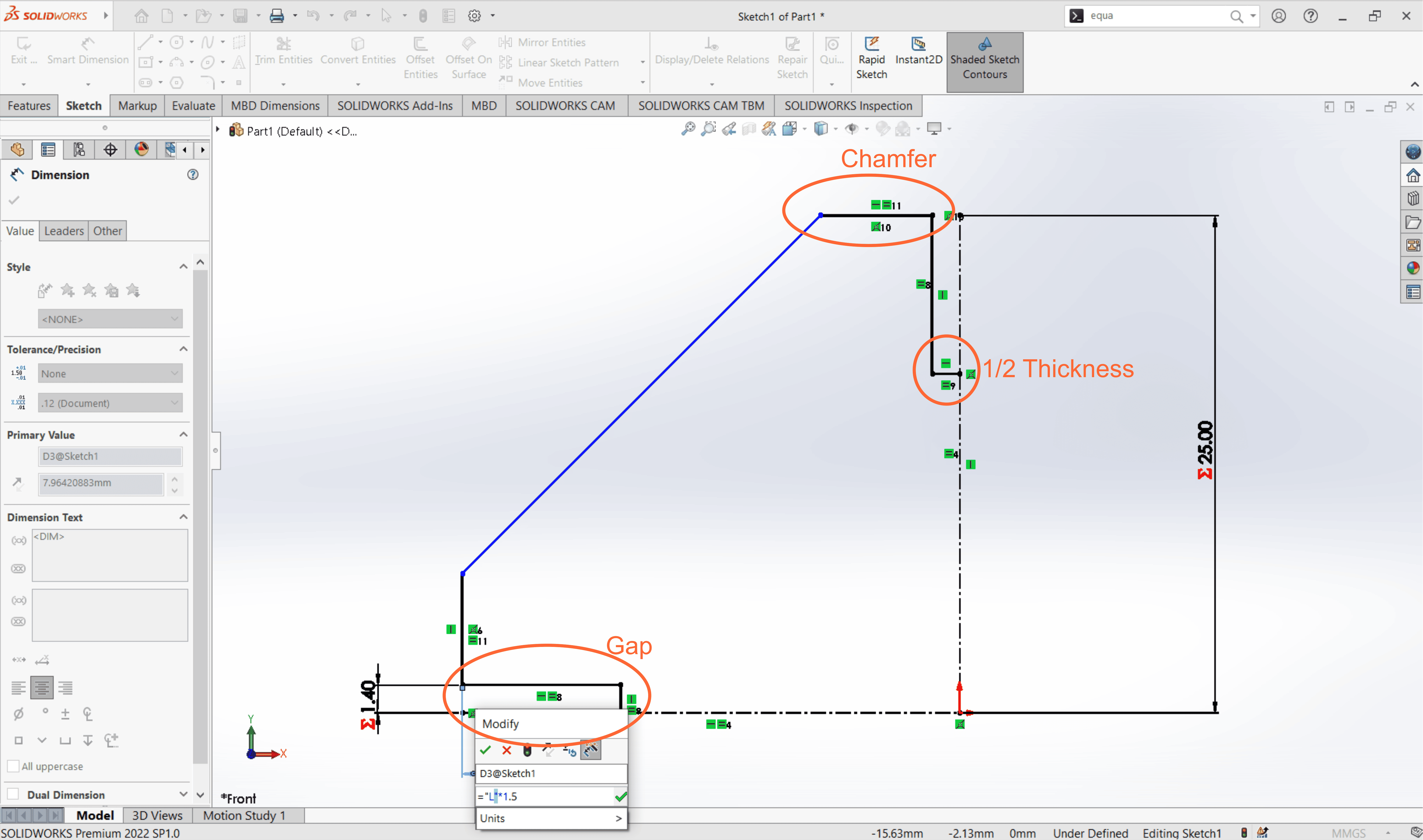
I used mirror tool to create a copy to the right side about the vertical construction line.
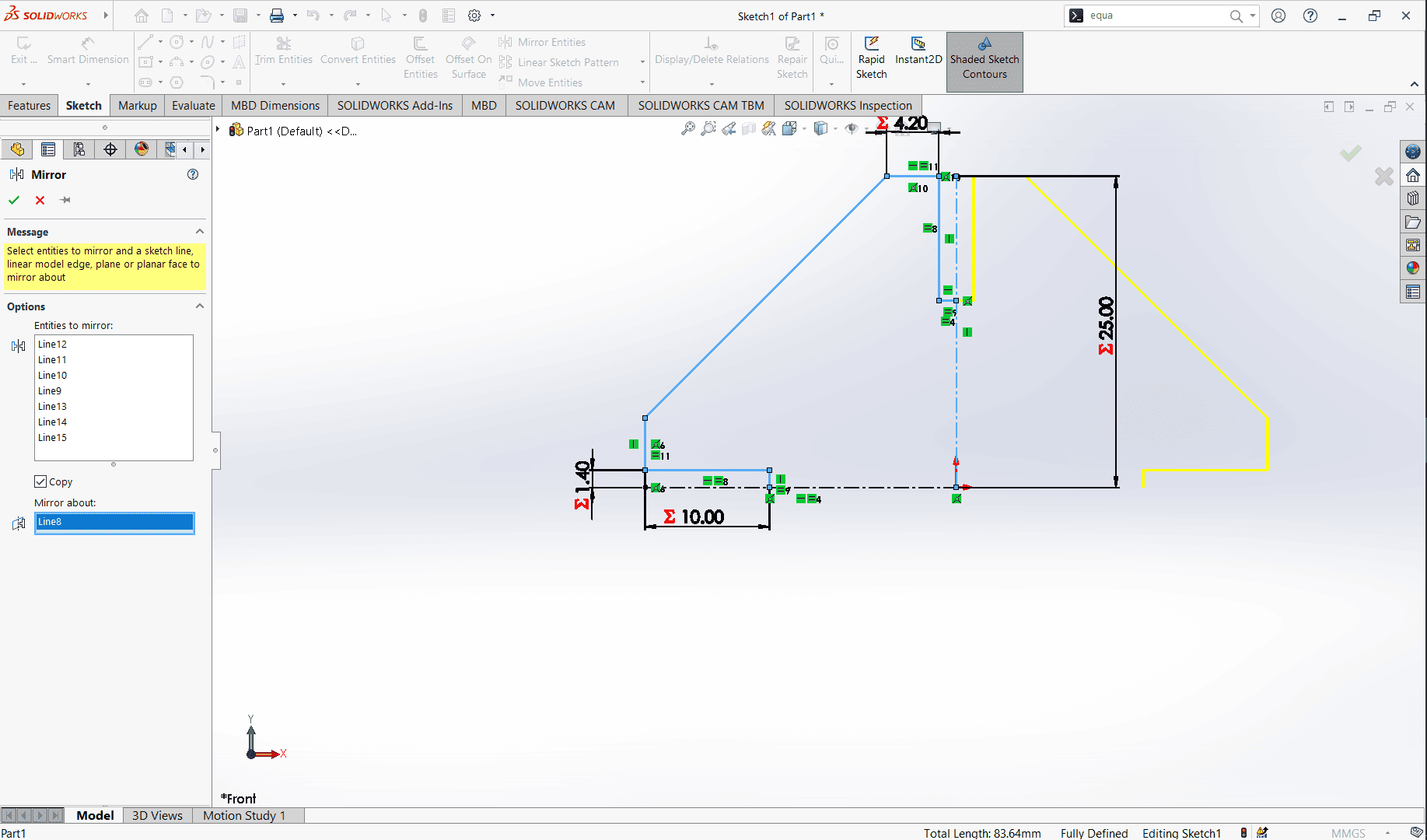
Then I created a copy with mirror about the horizontal construction line.
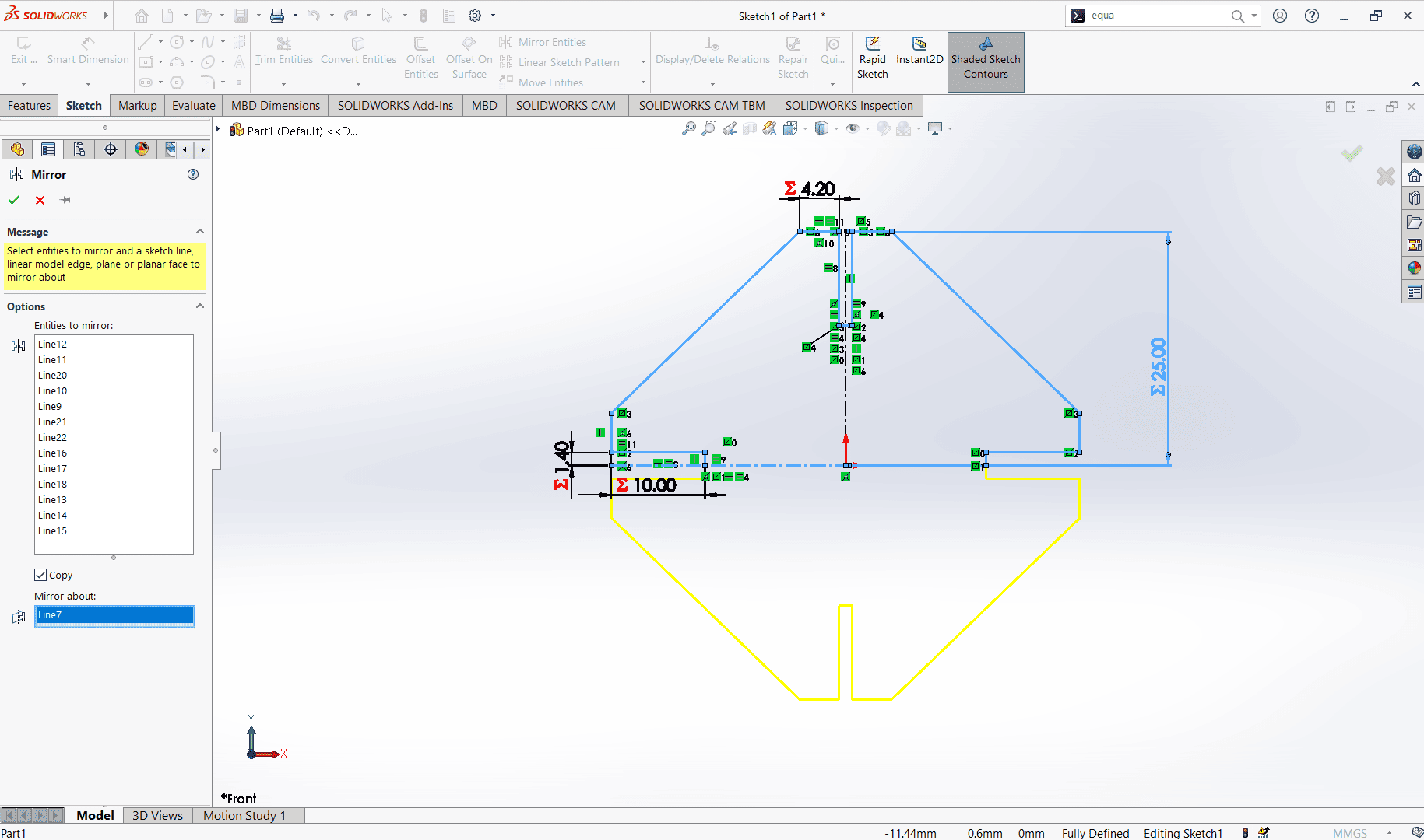
Here now I have my complete full defined sketch > exit sketch > Extruded Boss Base of 2.8mm
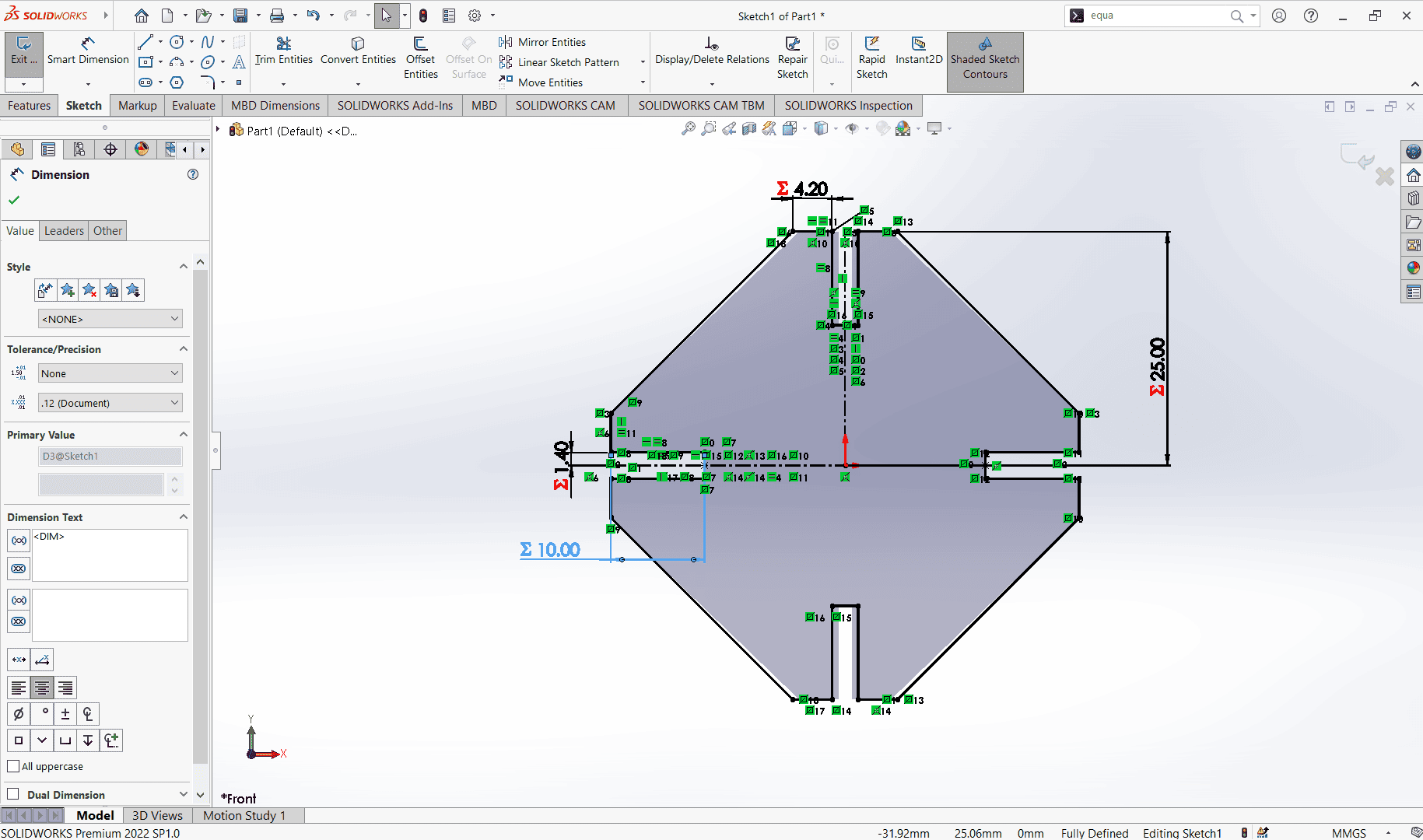
Under the Boss-extrude panel, I set the extruding dimension as T since it is the material thickness.
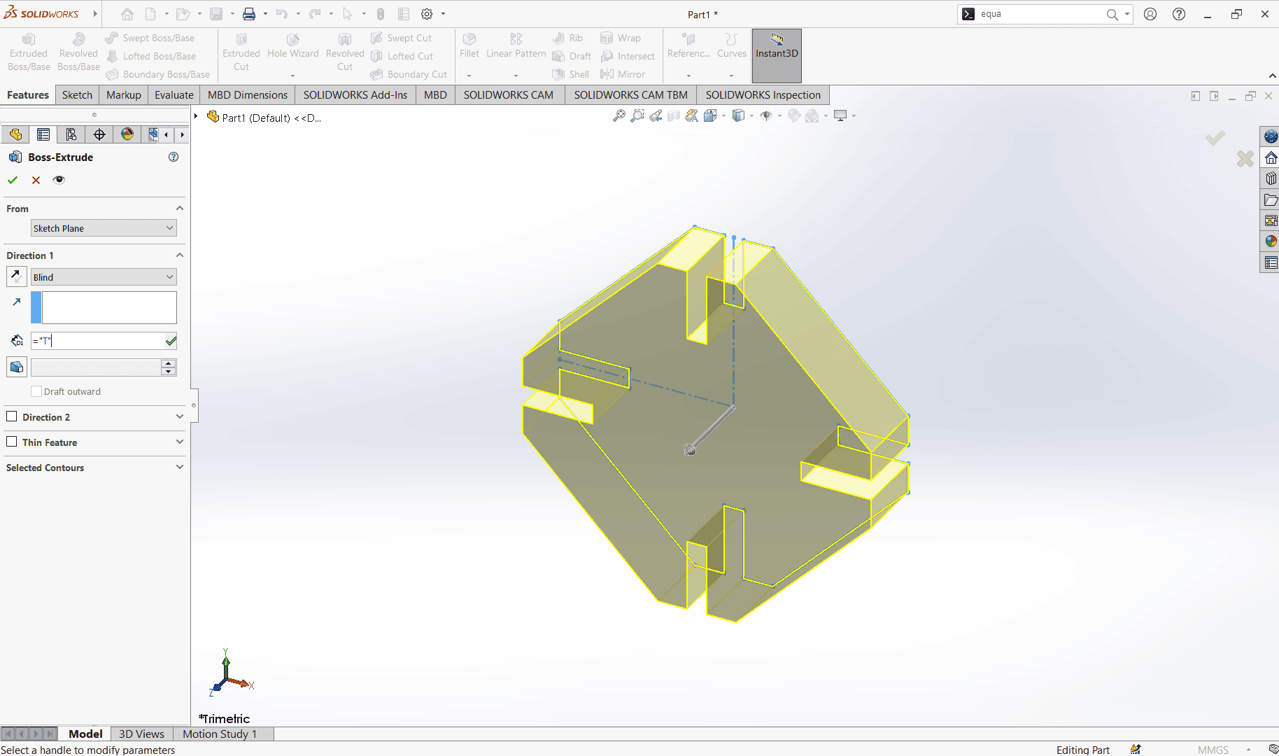
After extruding my pieces was done and the next think was to create copies and assemble them to have a clear view of the parametric kit.
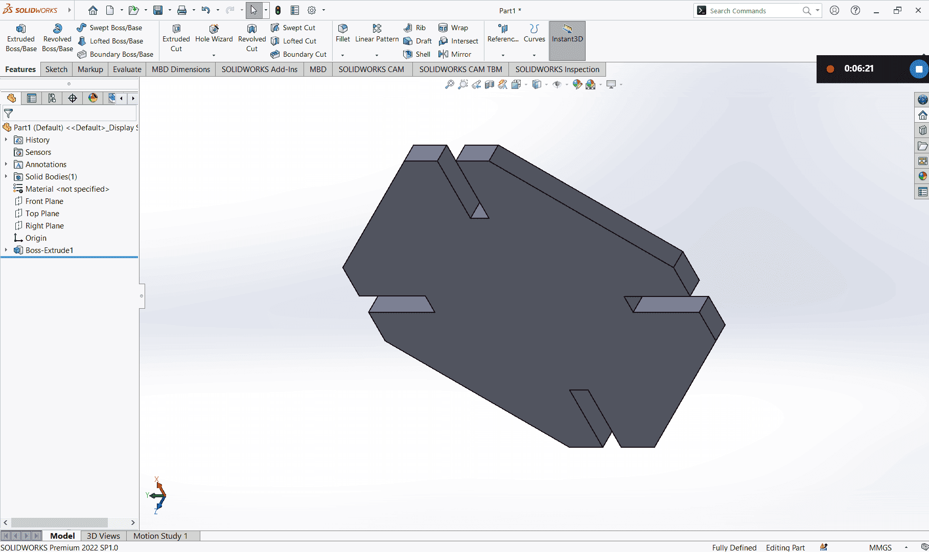
Assembling
At this stage I opened Assembly document
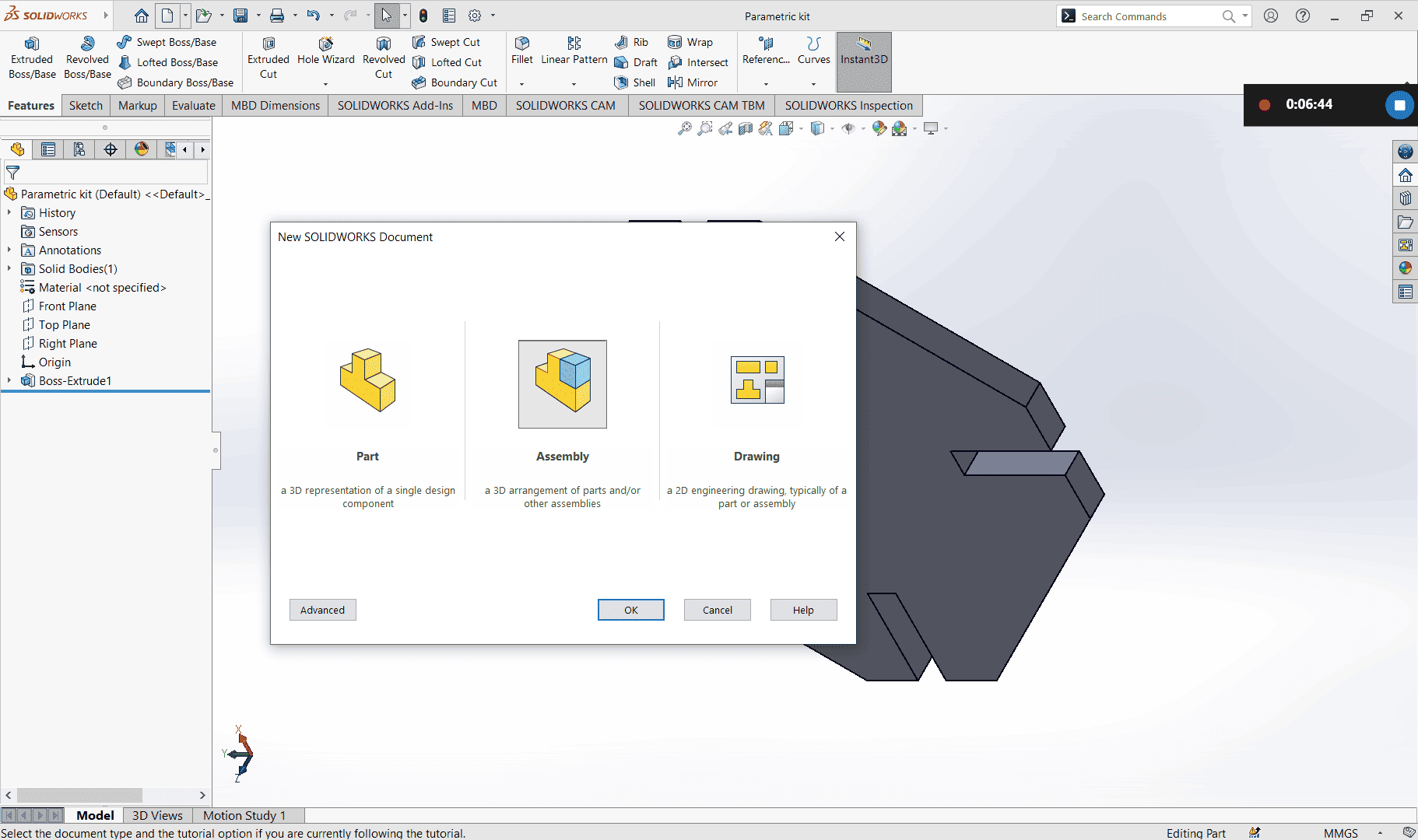
From here I could see my piece on the left, I had to click and drag it to assembling area.
The first piece in assemble is always fixed, I had to right click and choose float so that I
can be able to move it.
After selecting float, I applied mates so that my piece can be were aligned (front plane to front plane, orgin to orgin with alignment)
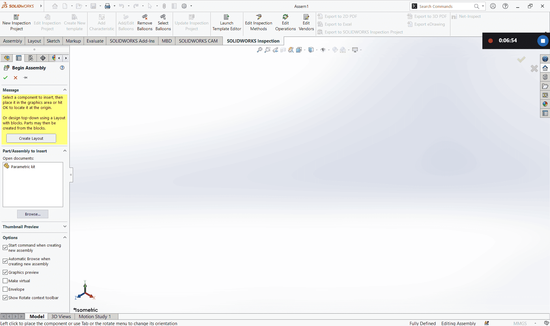
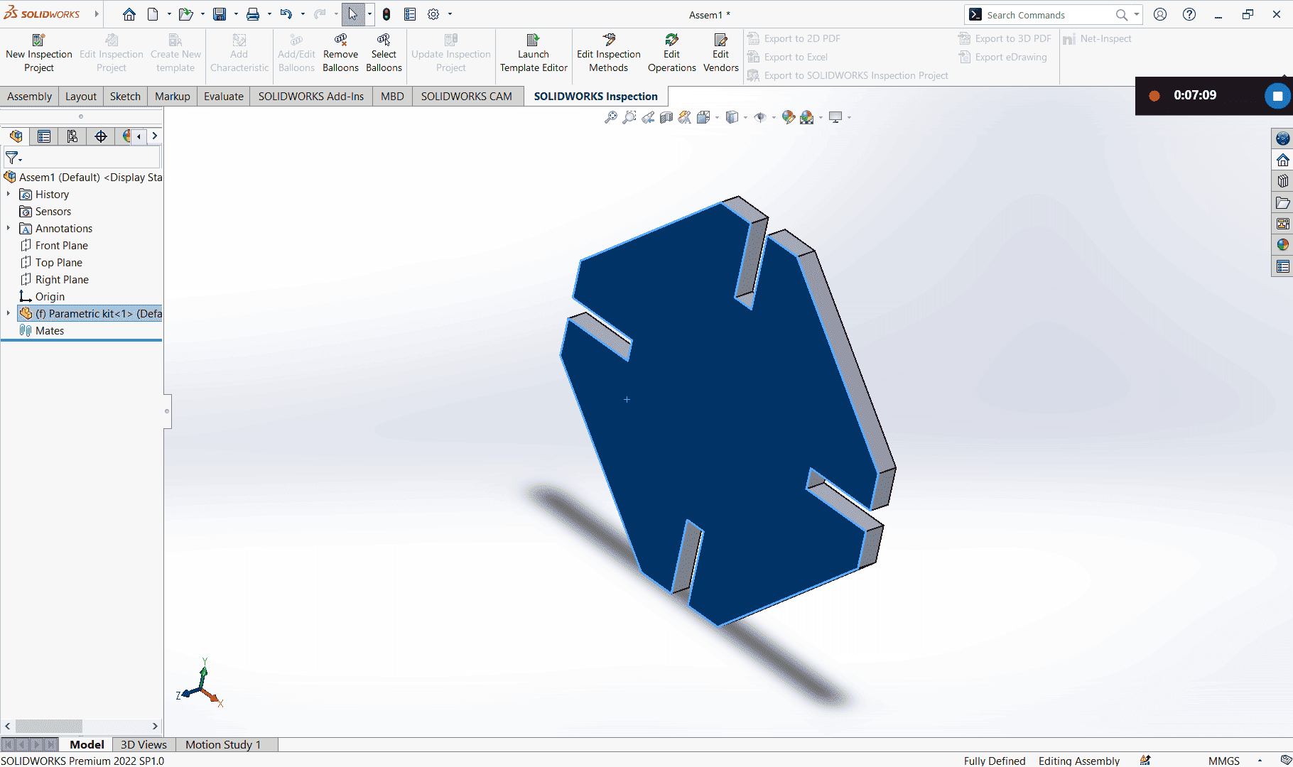
The next step was to create copies of my peice by holding Ctrl key clicking inside my peice and drag a side. A new copy is created.
I then applied collinear mate property to three of the joint faces to make my object properly joined.
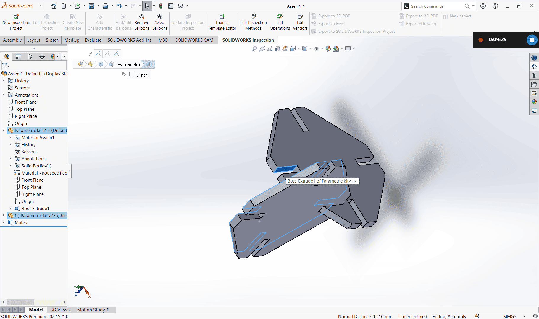
I went on creating copies and mating them
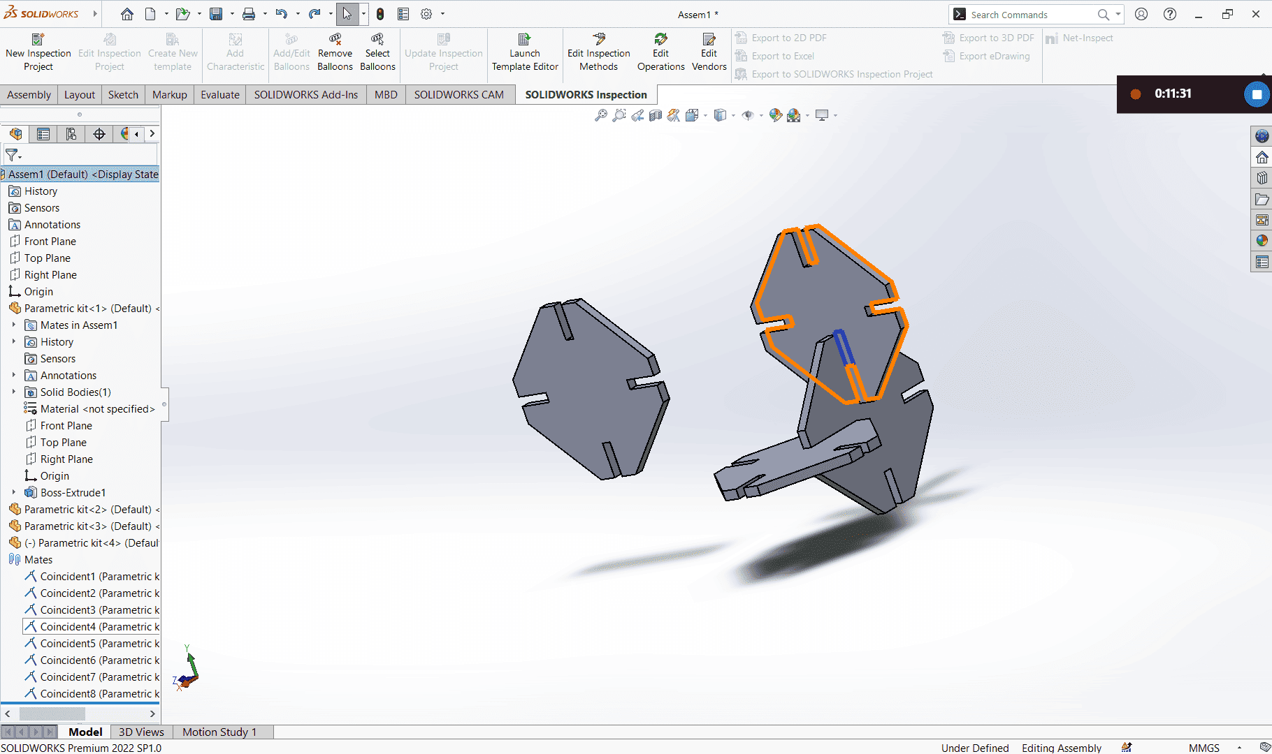
After creating multiple pieces, this is how my parametric was looking like.
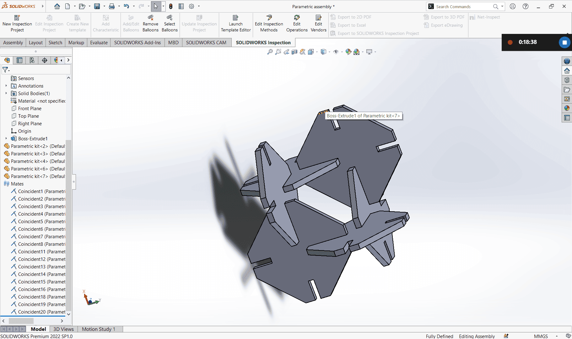
After all I saved my assembly project.
Since my assembling was fine I went back to the piece drawing to save a dxf file for cutting on the laser.
Saving DXF file
In my piece drawing I selected the the front face > Right click > Export to DXF / DWG
Choose file name and save type (DXF) > Save
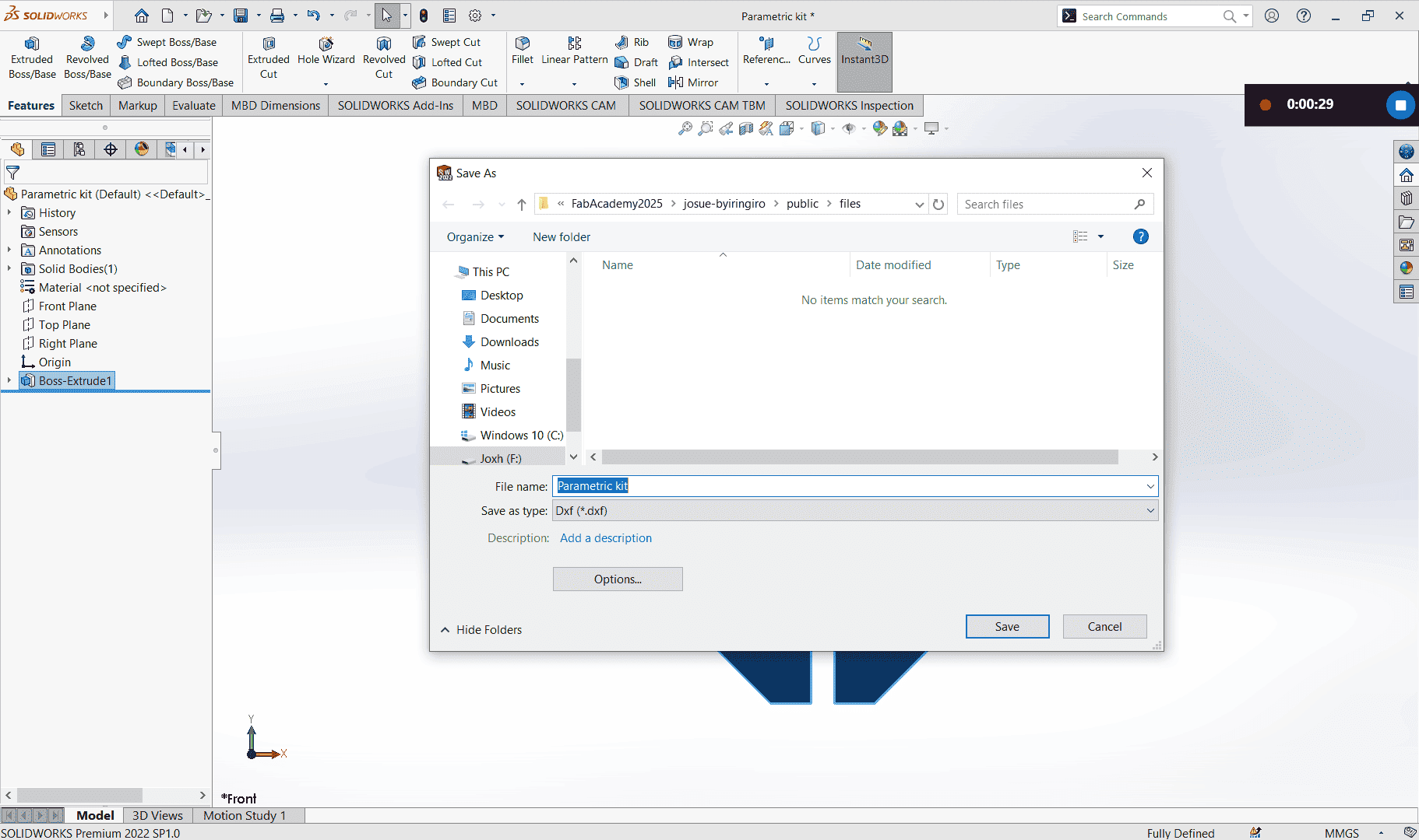
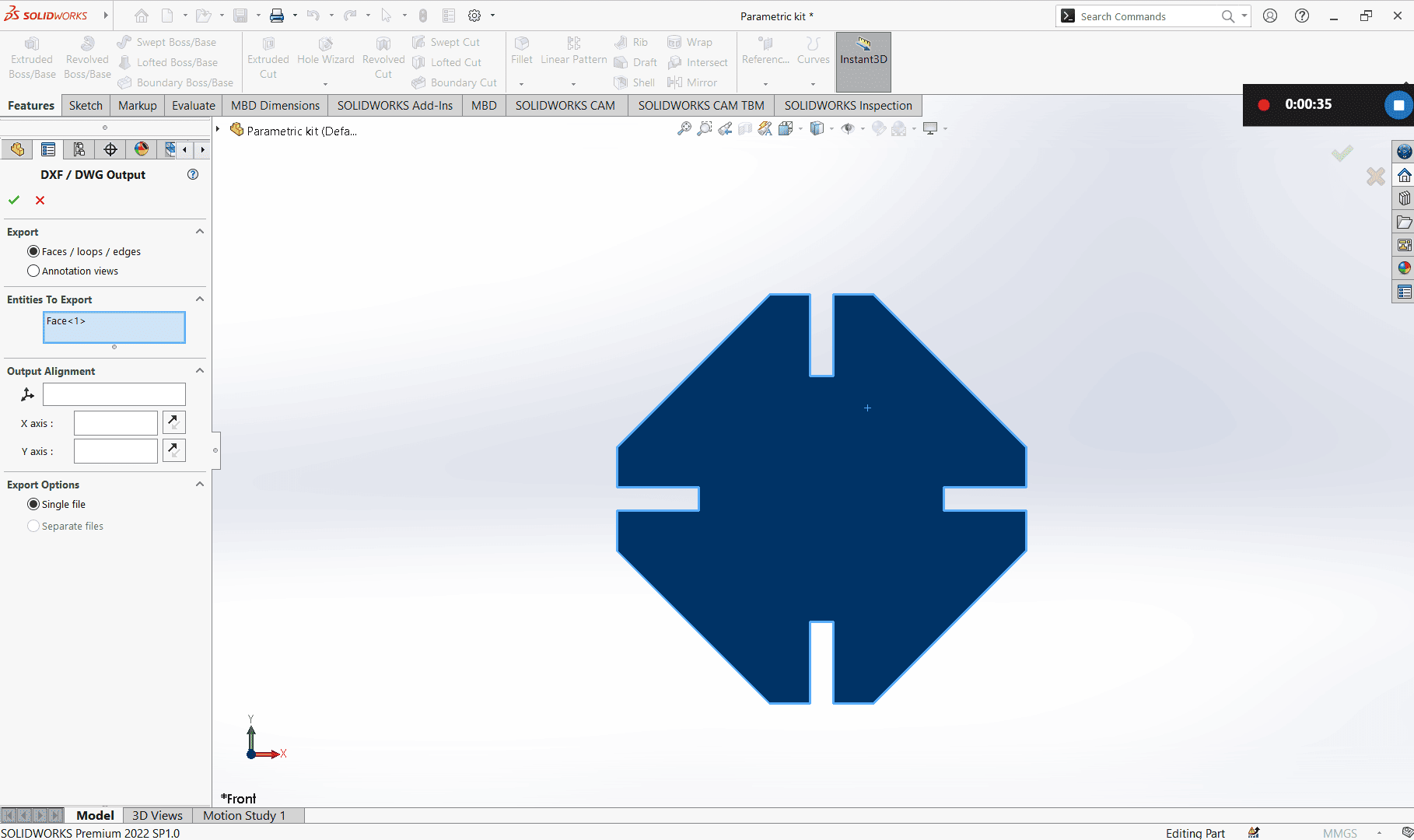
Front the DXF/DWG output panel I chose Face > Ok
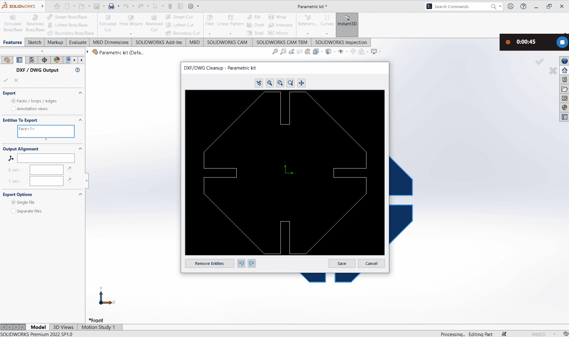
The preview panel pops up and check if the shape you neeed is the same as the showed one then save.
I imported my drawing into the laser cuttin software Created the number of pieces I needed.

Finishing setting the cutting parameters, I placed my sheet on laser bed > took focus (auto) > closed the lid and sent my job

After cutting my pieces it was time to assemble them.
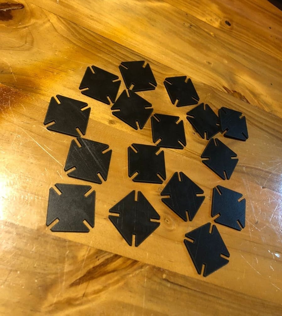
Finally here is my assembled paremetric kit.

Design file: Parametric design
Assembly file: Download
Dxf file: Download
Vinyl Cutter
A vinyl cutter is a machine that cuts designs out of vinyl material using a sharp blade.
With my design of logo initials I played around with Roland Gx-24 vinly cutter.
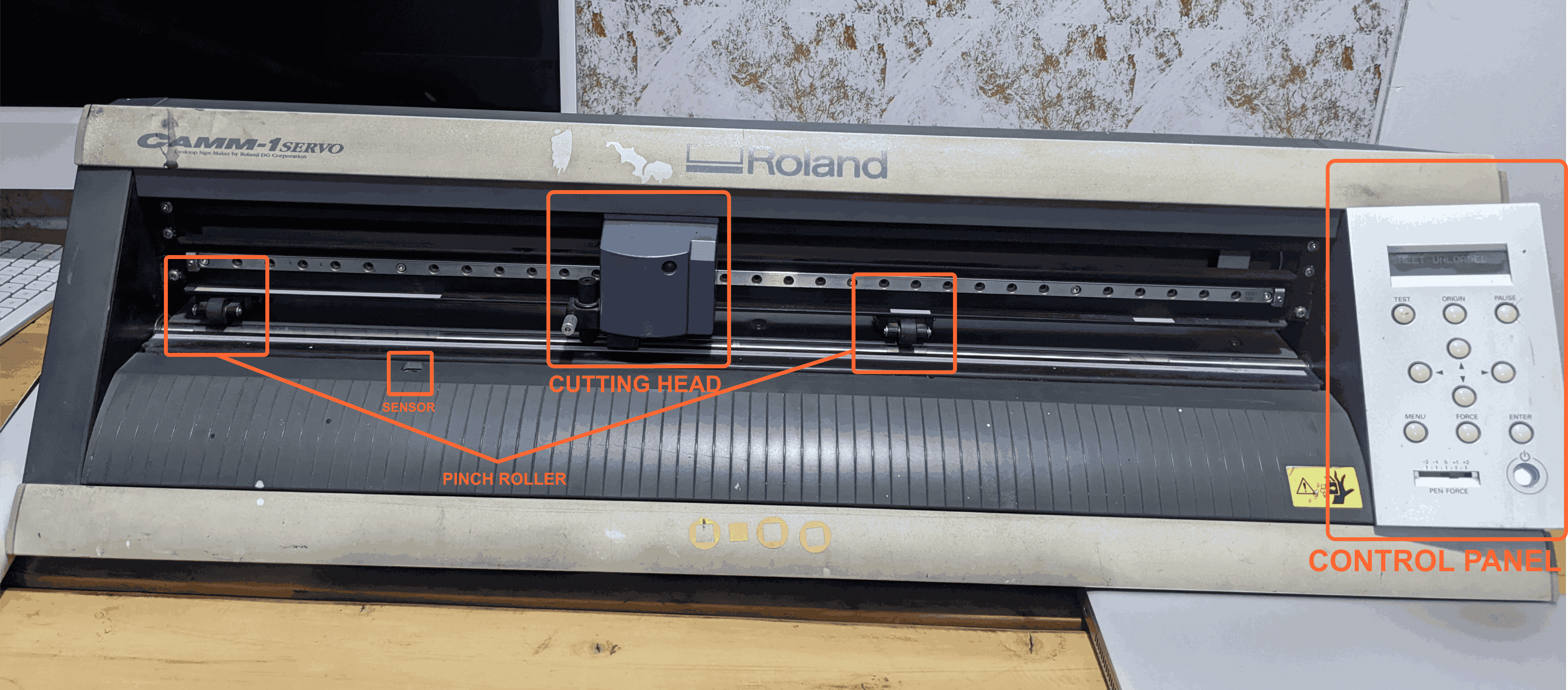
Parts of the vinly cutter
1. Control Panel: It helps to set parameters like cutting speed, force, and start and pausejob.
2. Cutting head: That is where an adjustable blade is mounted
3. Sensor: it helps detect the position of a material.
4. Pinch Rollers: rollers helps to hold tight material in place.
Getting started
Using corel draw, I opened my logo from the computer aided design week and changed it to hairline and resized it.

After geting the design ready, I placed my black sticker on the vinly cutter.
I had to make sure the sensor is covered and adjust the pinch rollers to proper positions to hold my material.
Note: Pinch rollers have to placed exactly on the white marks, unless you will get a bad position message from the screen.
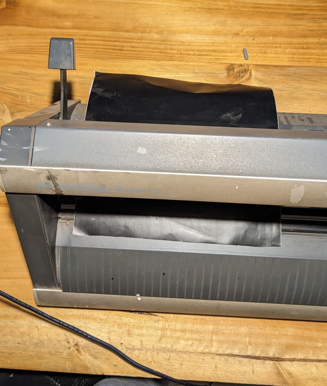
After placing the material, I selected sheet and press enter to get material size
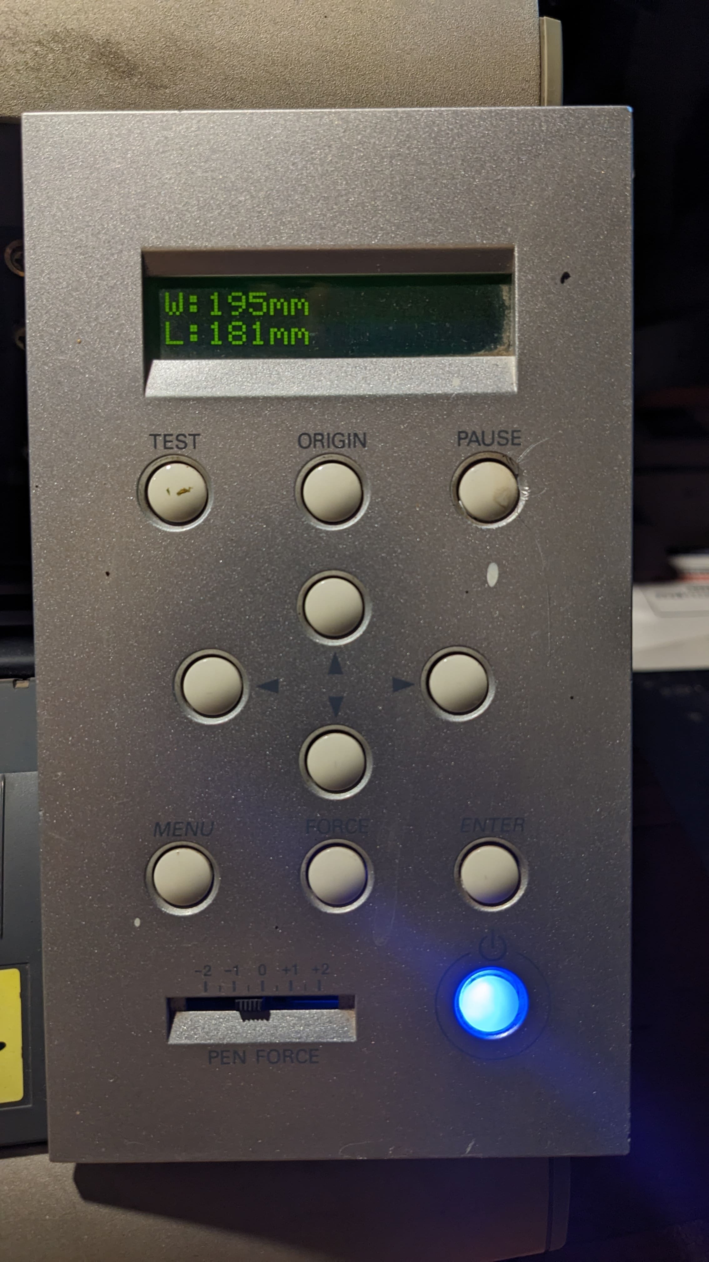
Cutting
After having the design ready and material ready I connected my vinly cutter to the machine with USB Type B cable.
Note: To be able to print from coreldraw you must have roland Gx-24 drivers installed on the computer.
Download Drivers:Roland Gx-24 Drivers
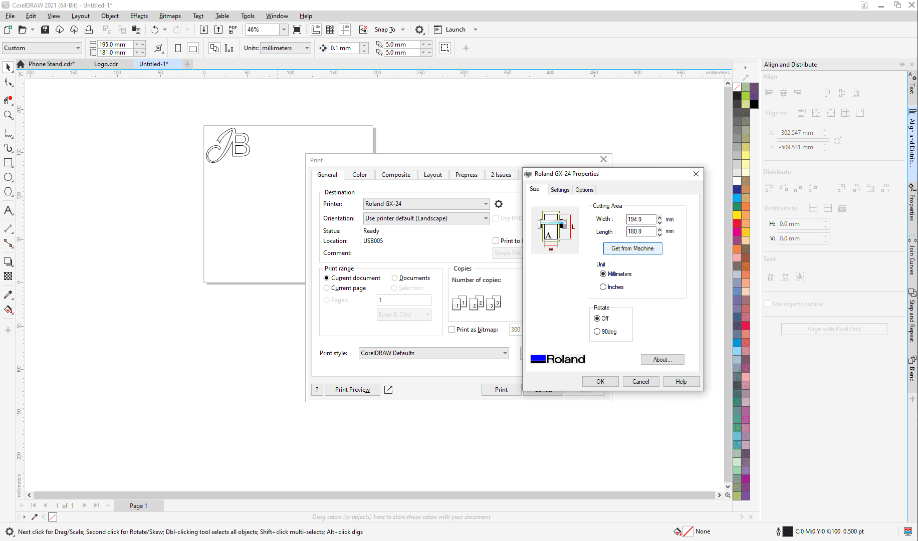
In coreldraw, I chose print> On Printer Tab: selected Roland Gx-24
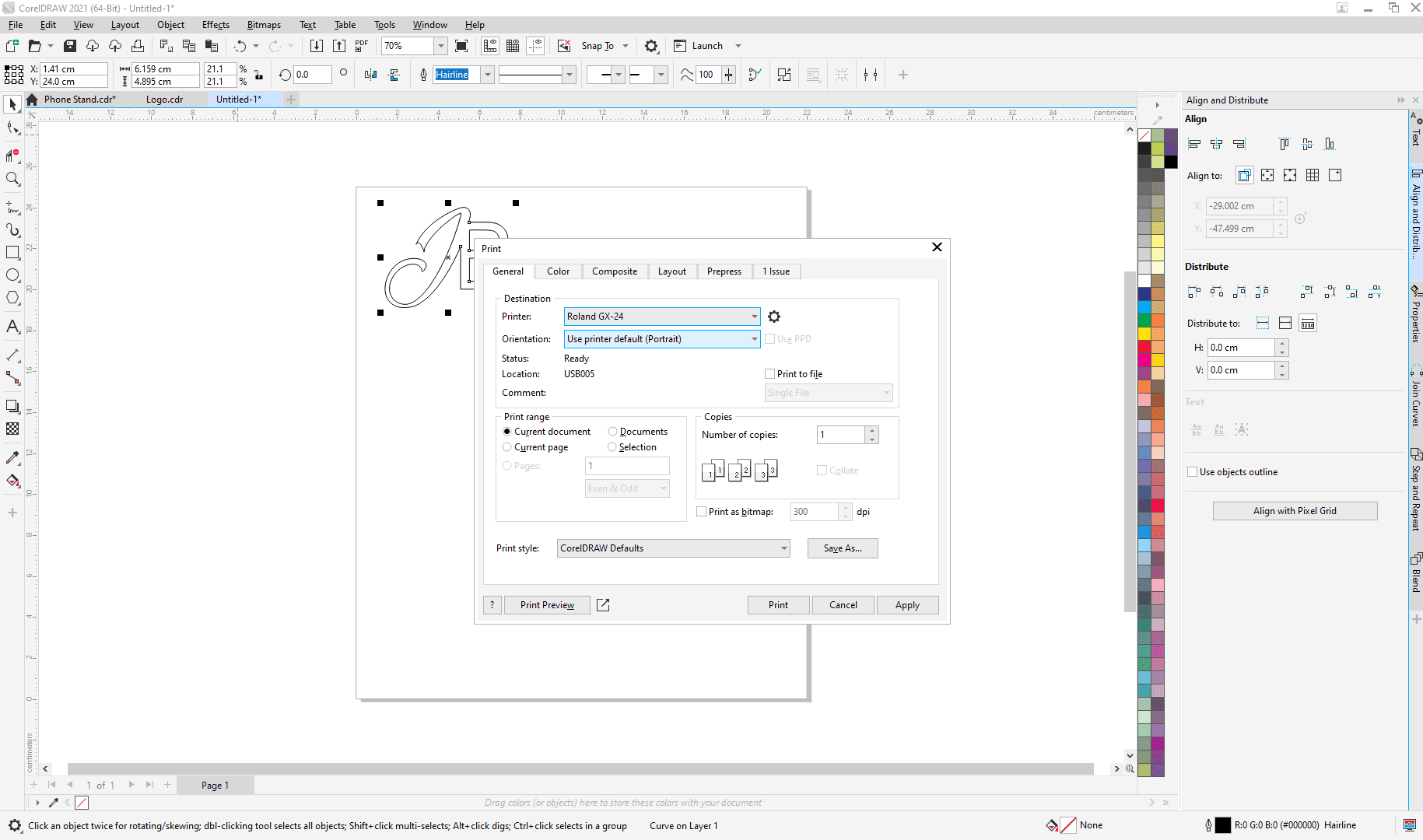
Clicked setting icon to access printer settings > selected Get from machine (to get material size the vinly has calculated)
Then OK > Appy > Print
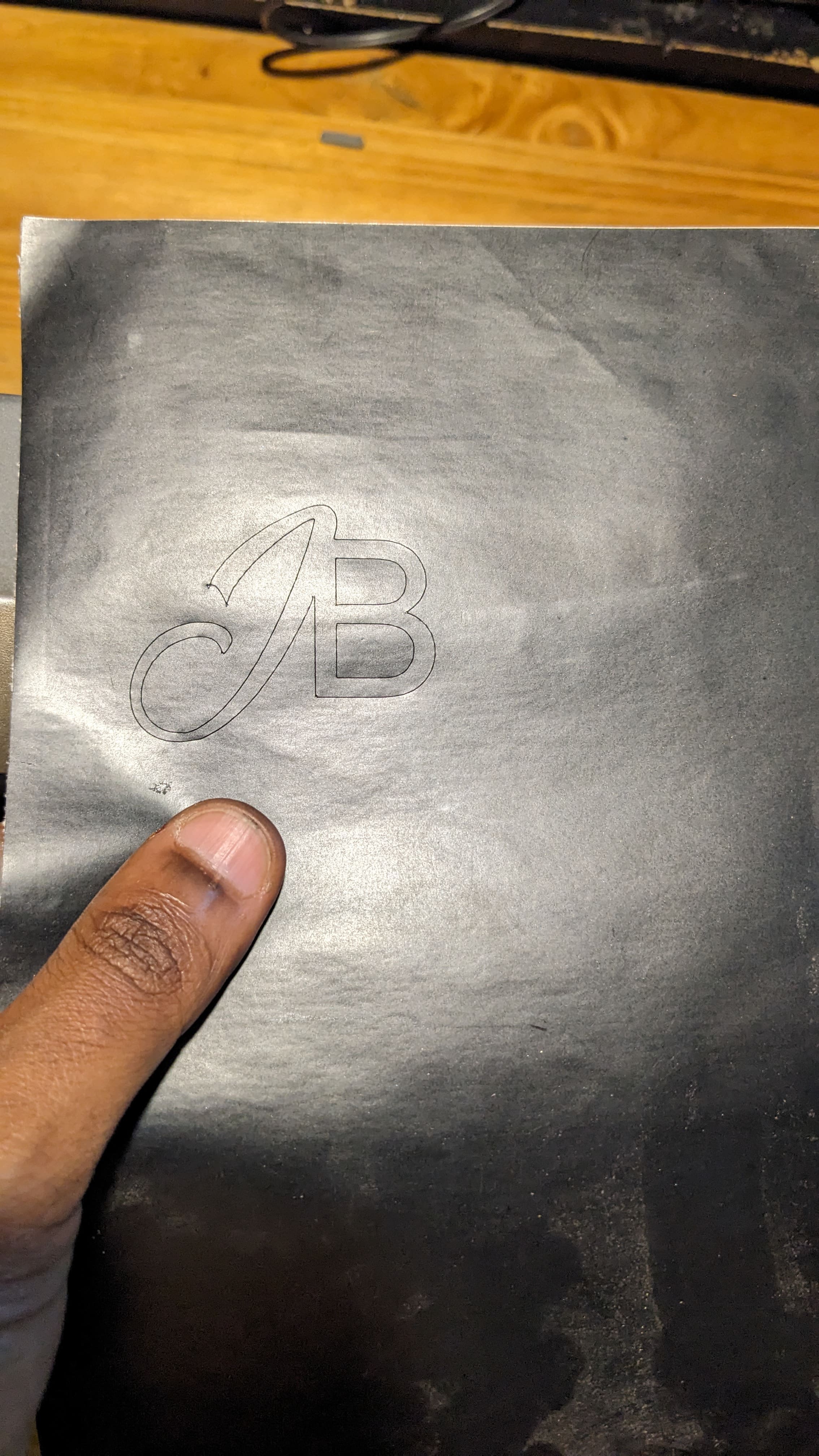
After cutting my logo I sticked it on my computer
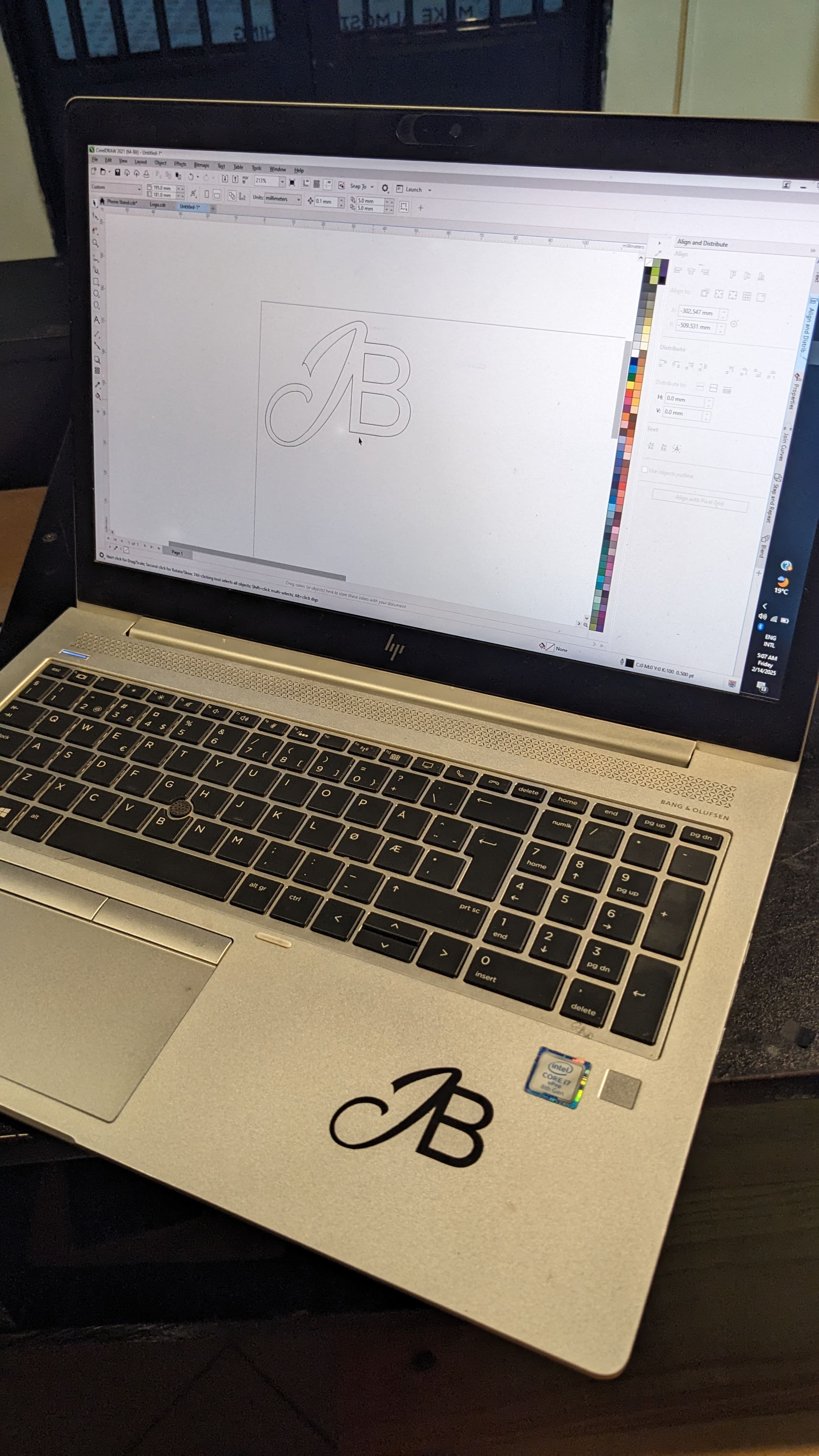
With this method I used, you can also use it with other softwares such as Illustrator
but you have to make sure that your vinly printer drivers are installed on the computer you are using.
Design File:Vinly Cutter