Week 8 - Electronics Production
Assignment
Group assignment:
Characterize the design rules for your in-house PCB production process: document feeds, speeds, plunge rate, depth of cut
(traces and outline) and tooling.
Document the workflow for sending a PCB to a boardhouse
Document your work to the group work page and reflect on your individual page what you learned
Individual assignment:
Make and test a microcontroller development board that you designed
Summary
I revisited the circuit design created during Electronic Design Week and exported it as an SVG file. I loaded the SVG into ModsProject to generate the G-codes for the toolpaths. Using OpenBuilds, I ran the G-codes on the CNC 3018 machine. Afterward, I proceeded with soldering and testing the circuit board, using programs to control the LED and push button. The circuit was fully functional.
Visit Group Page
Plotting PCB
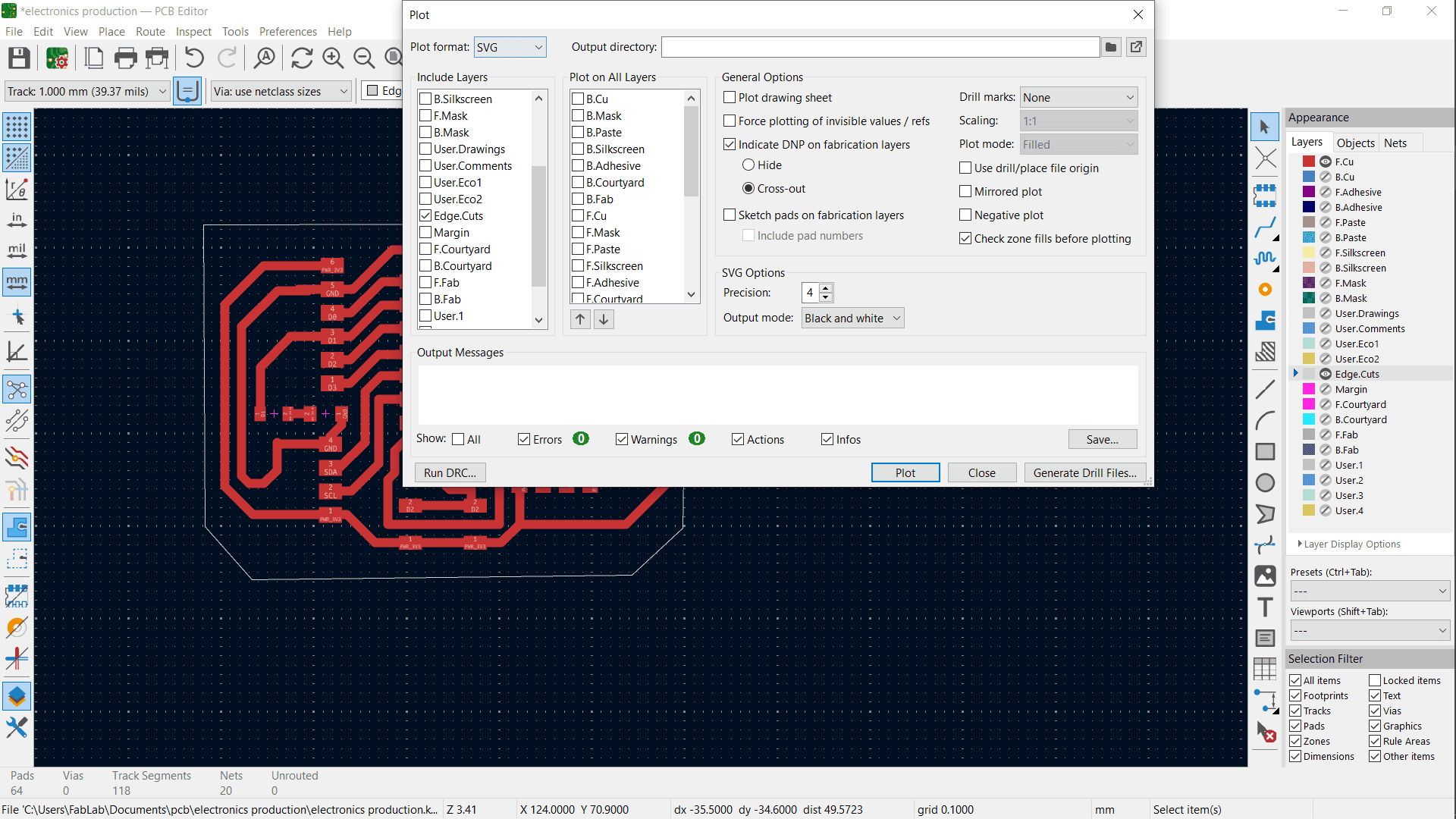
Clicked Plot in KiCad and selected SVG as the format.
Chose the layers to plot:
Edge Cuts
Front Copper (since the PCB is single-sided).
ModsProject
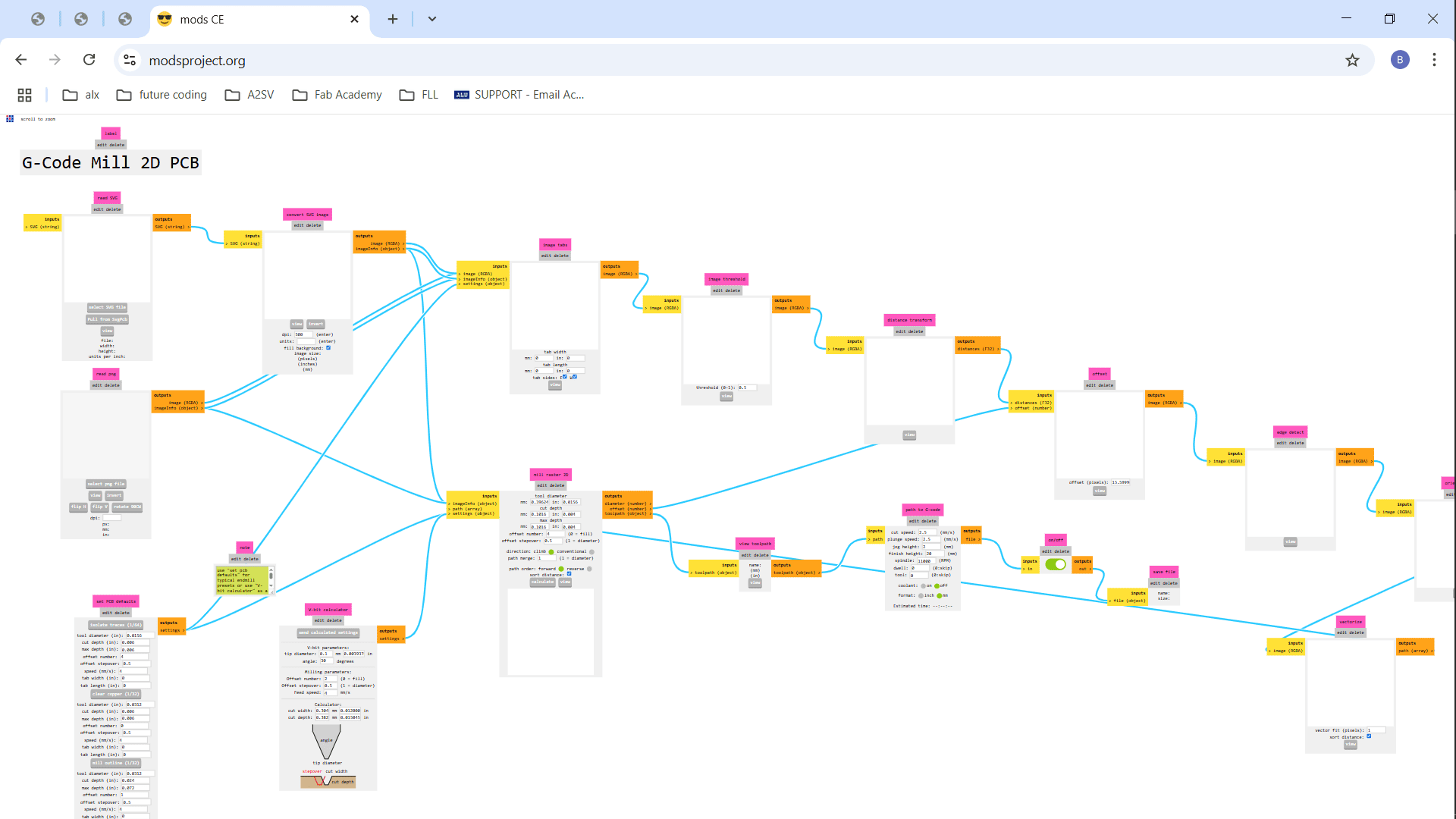
Saved the SVG file and opened ModsProject.
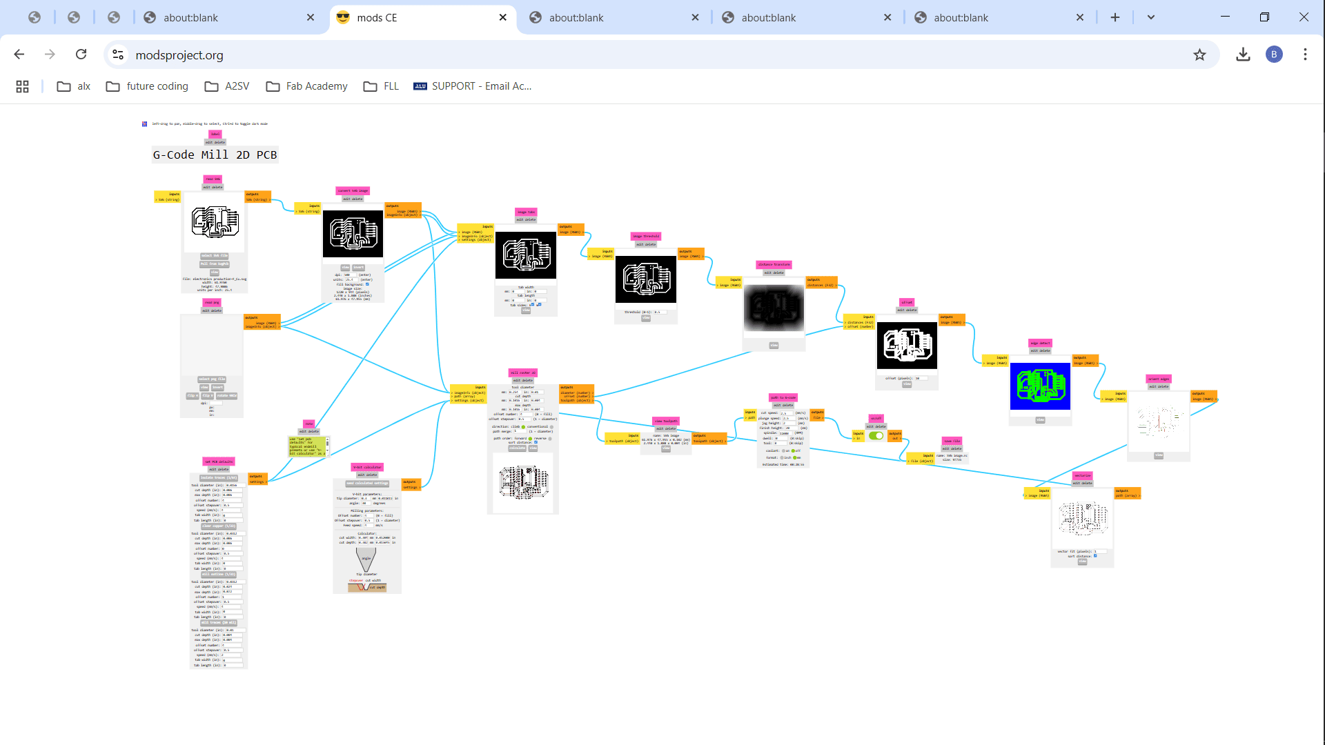
Chose the GCODE Mill 2D PCB program.
Imported the saved SVG file into ModsProject.
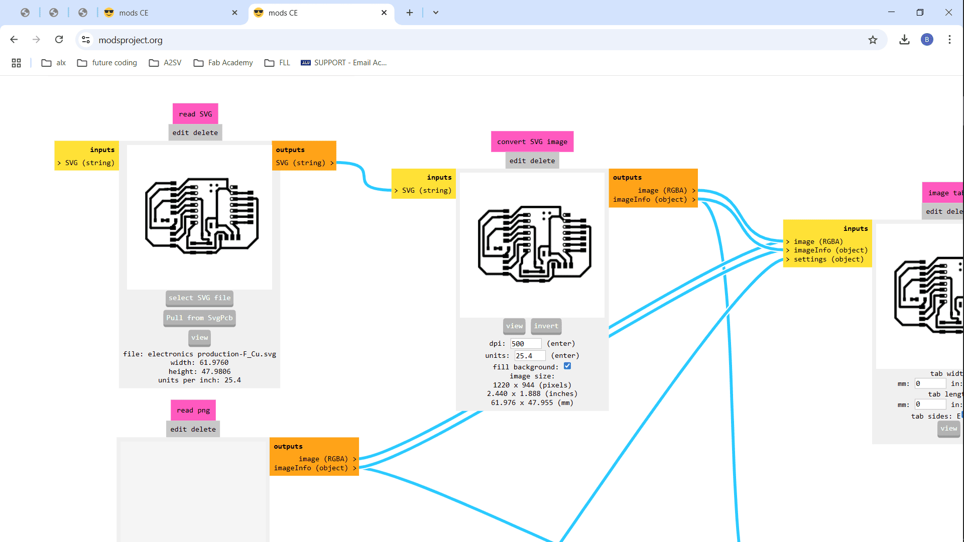
Under Set PCB Defaults, I selected Milly Trace
Moved to the V-Bit Calculator section:
Tip Diameter: 0.3 mm
Offset Number: 4
Sent the calculated settings to Mill Raster 2D.
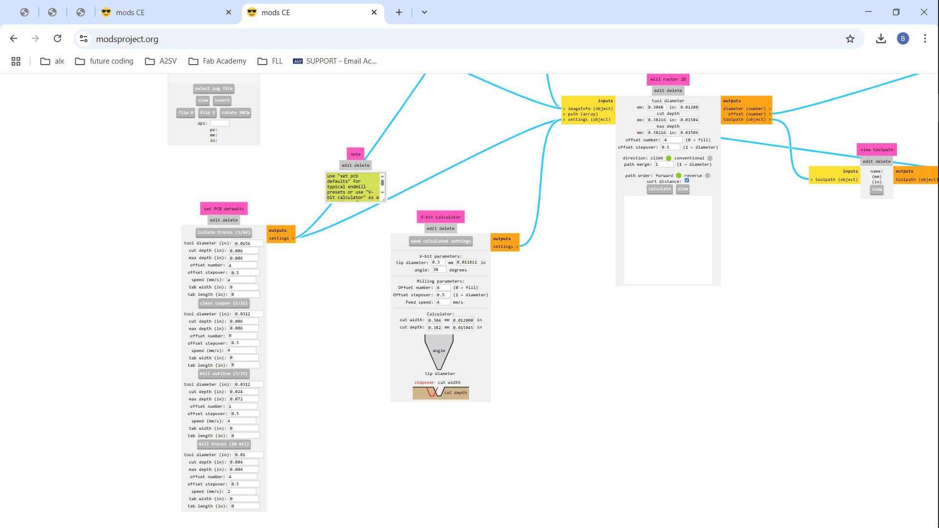
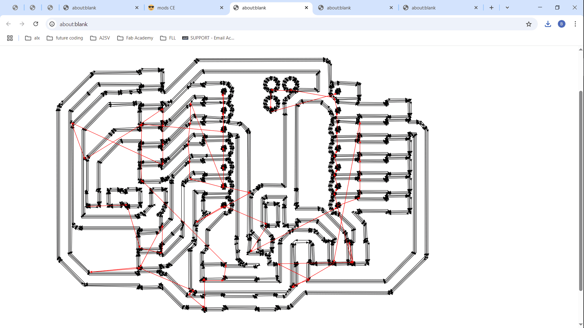
Moved to the Mill Raster 2D section and clicked Calculate.
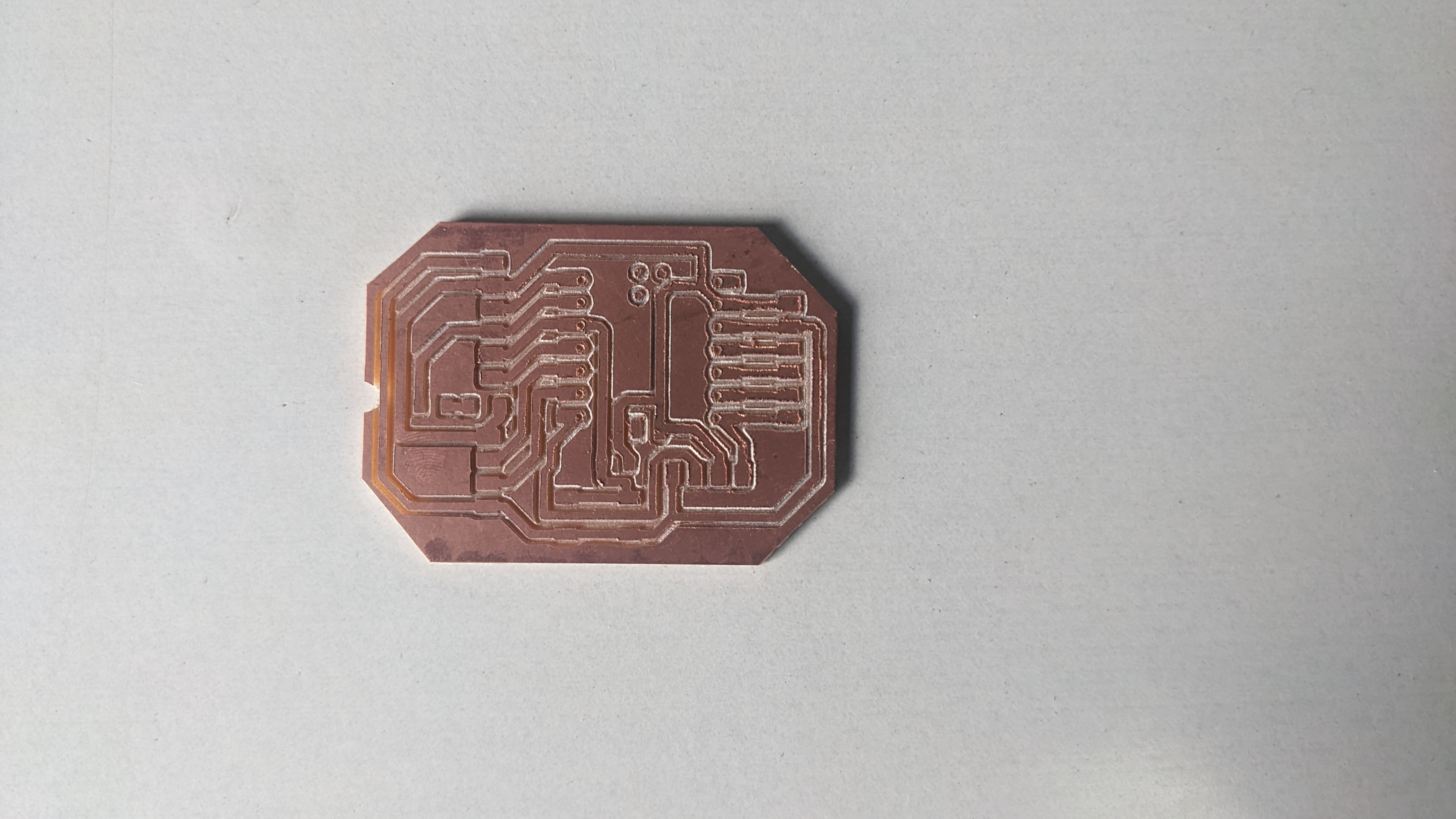
The G-code was generated and downloaded.
Milling PCB
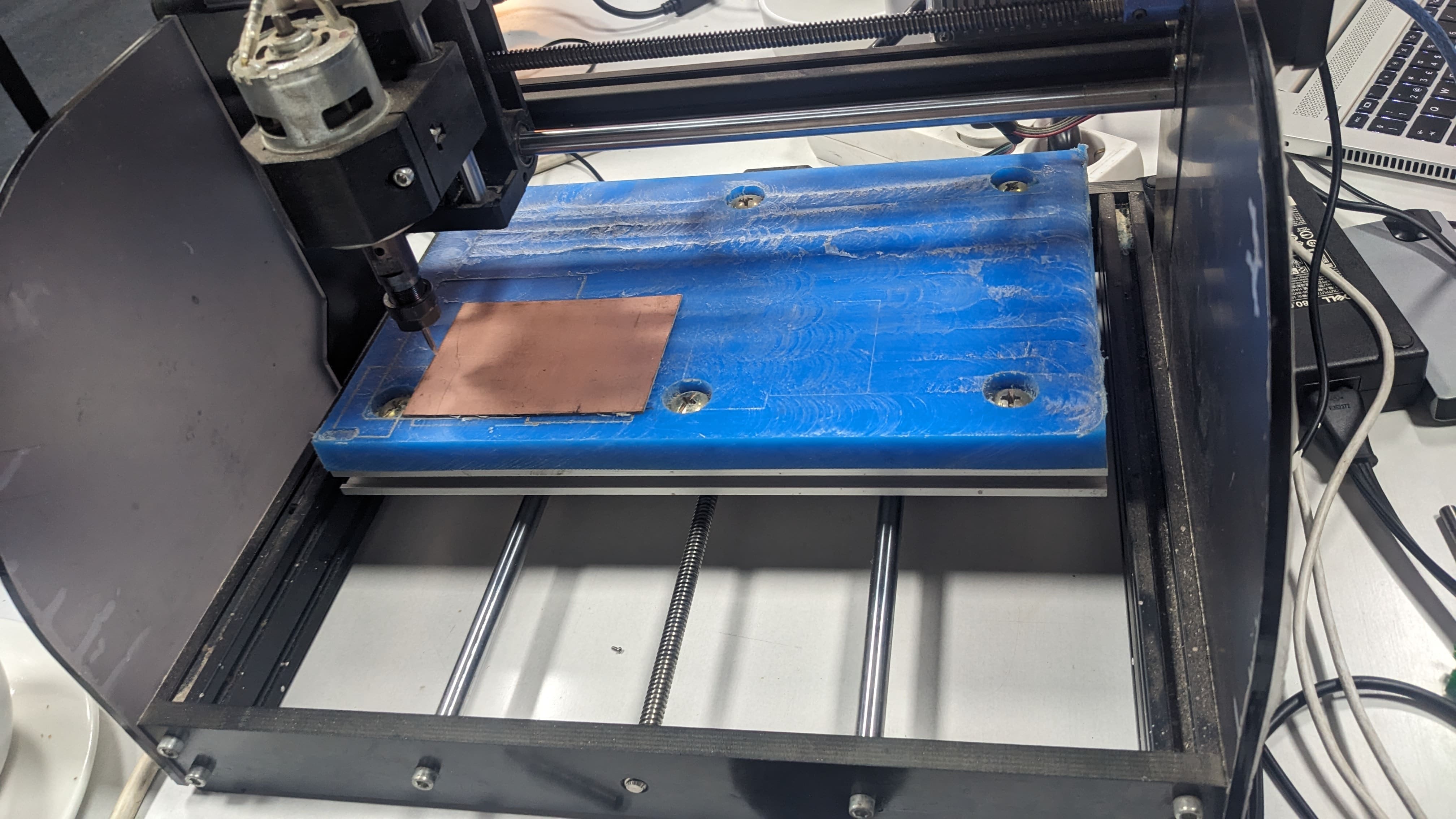
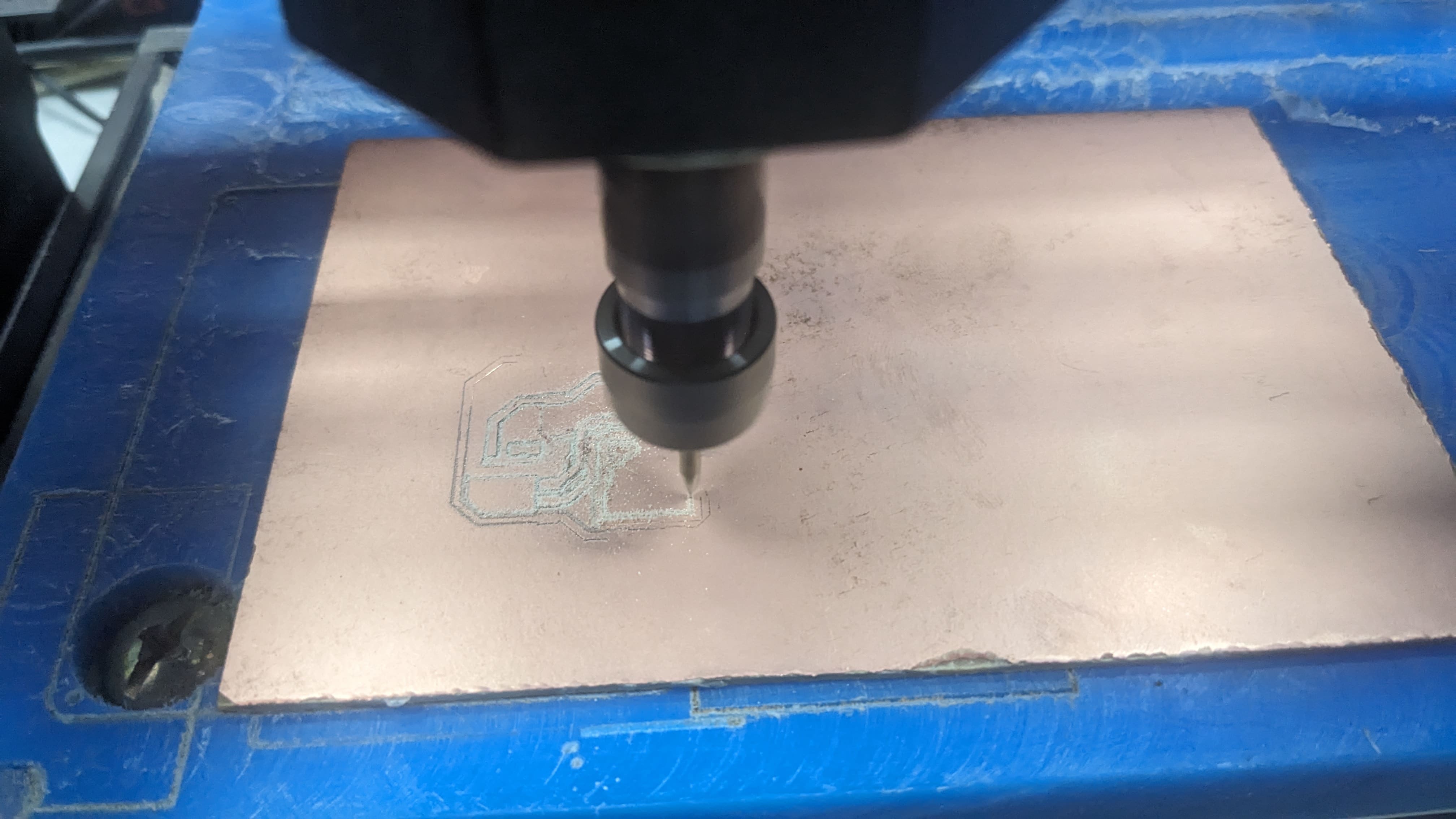
Using CNc 308 machine
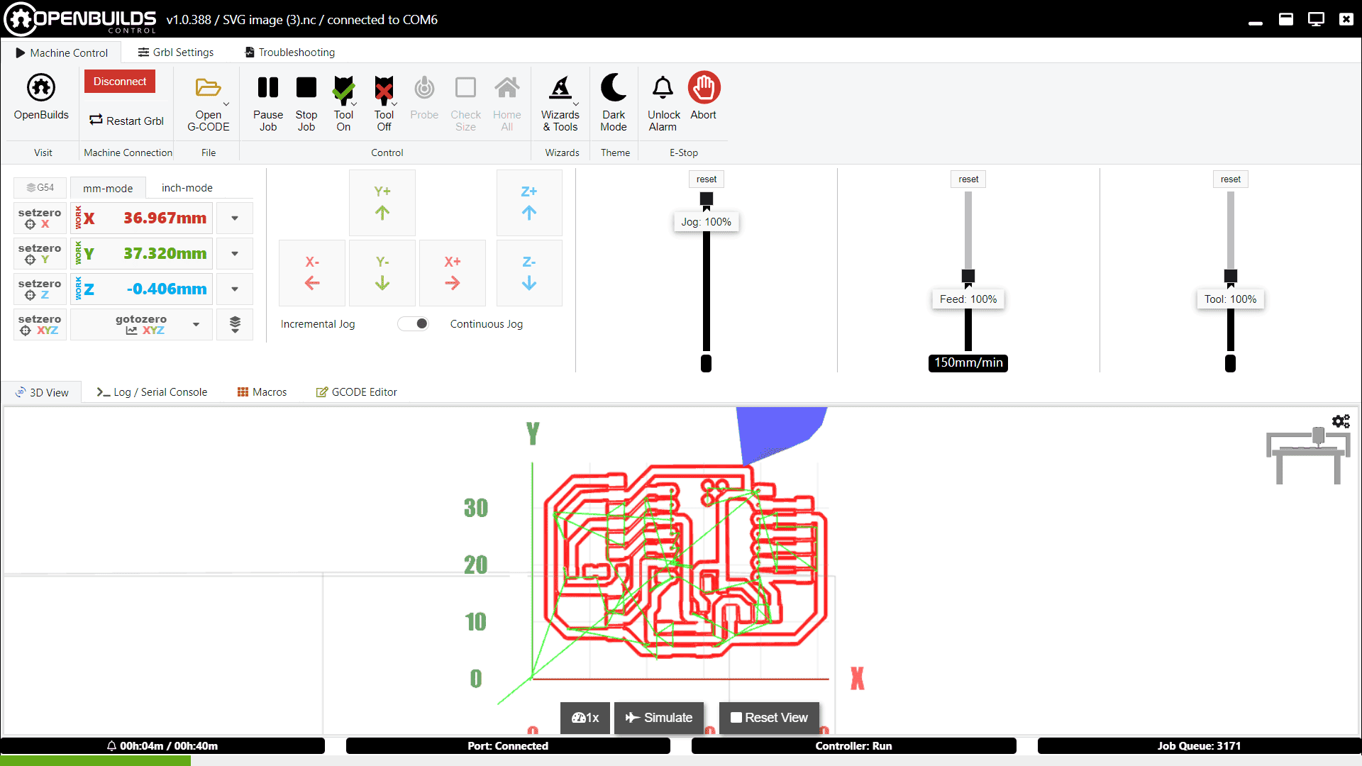
Moved to OpenBuilds and loaded the generated G-code.
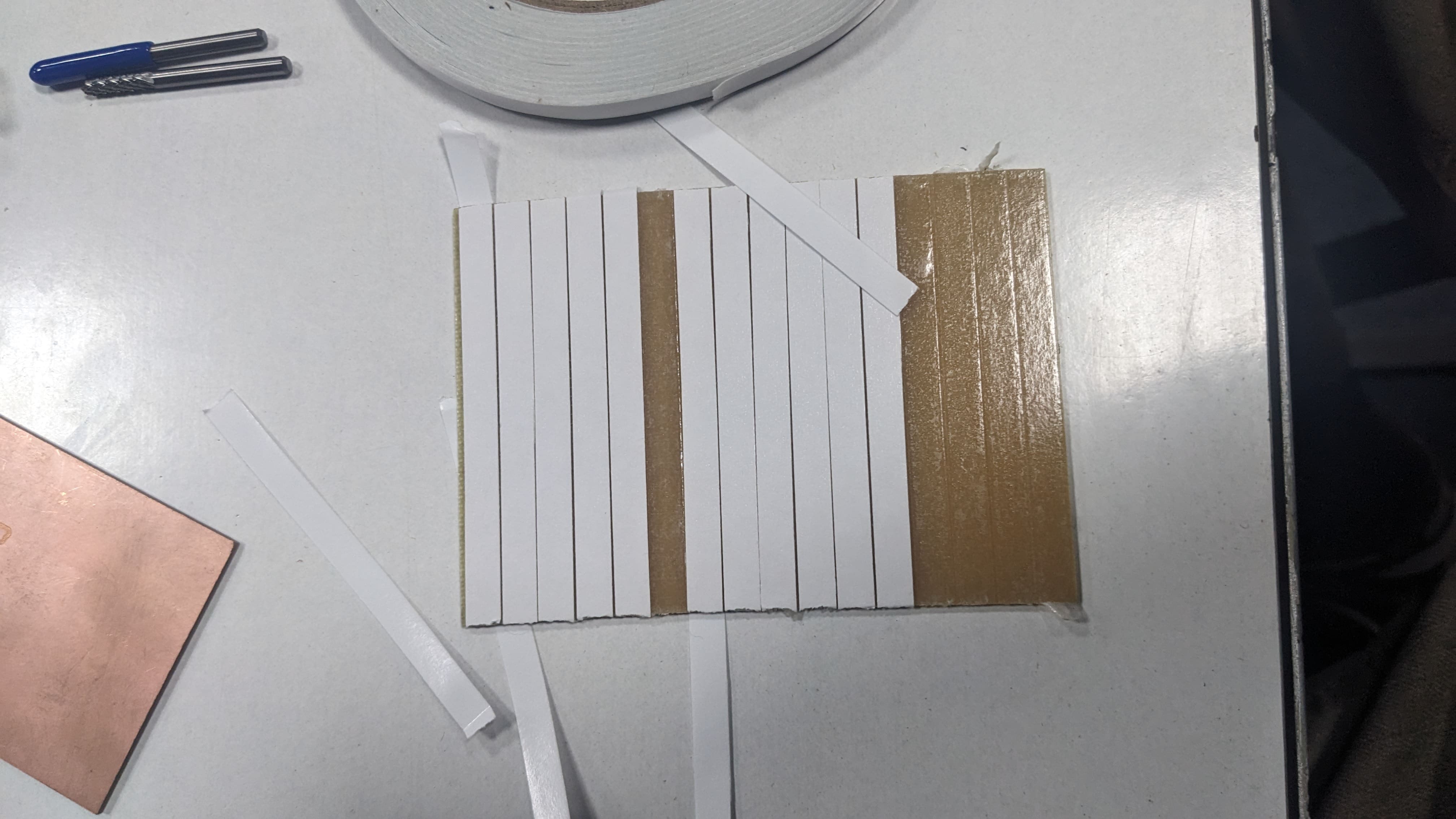
Fixed the copper board onto the CNC bed using double-sided tape.
Set the starting position (Home) and ran the job.
Soldering
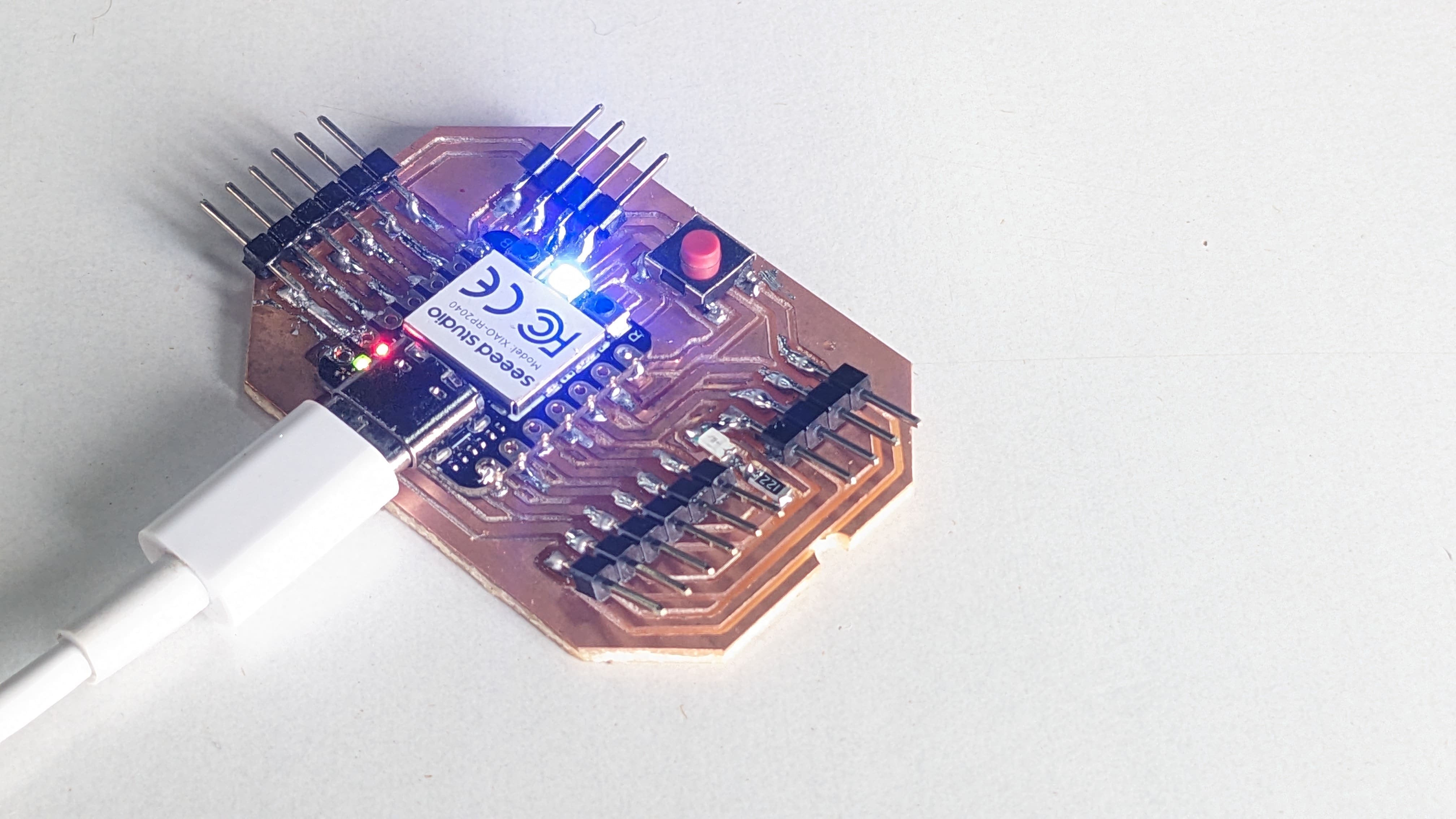
I soldered the components onto the board, including resistors, the LED, and the push button.
Testing PCB
I tested the functionality of thes board with a basic LED blinking program and a push button-controlled LED program. Both worked as expected.