Week 7 - Electronics Design
Assignment
Group assignment:
Complete your lab's safety training
Test runout, alignment, fixturing, speeds, feeds, materials and toolpaths for your machine
Document your work to the group work page and reflect on your individual page what you learned
Individual assignment:
Make (design+mill+assemble) something big
Summary
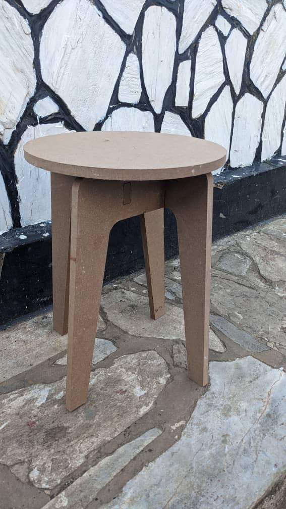
During the Computer-Controlled Machining week, I designed and fabricated a multifunctional stool that can also serve as a table. I used SolidWorks for 3D modeling, VCarve for toolpath generation, and the ShopBot CNC machine for machining. The final piece was made from 18mm MDF, and I successfully assembled all parts into a sturdy structure.
Group Page Link: Learning CNC operation, safety and prevention.
Parts Design
I began by modeling the parts in SolidWorks:
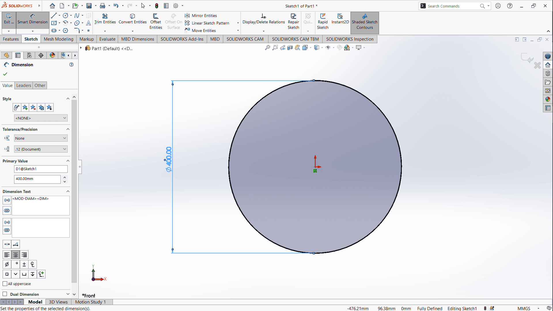
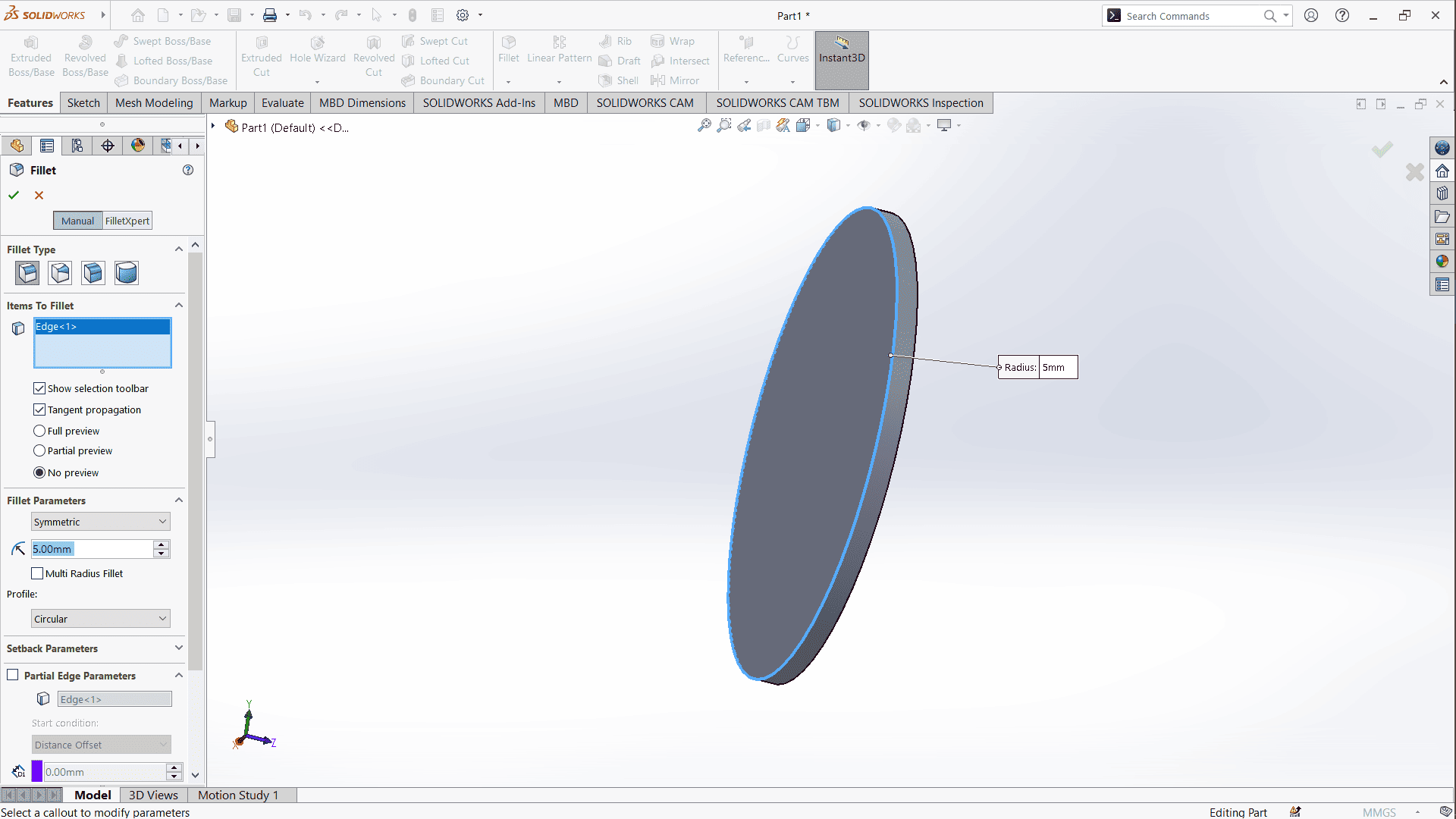
Top Part:
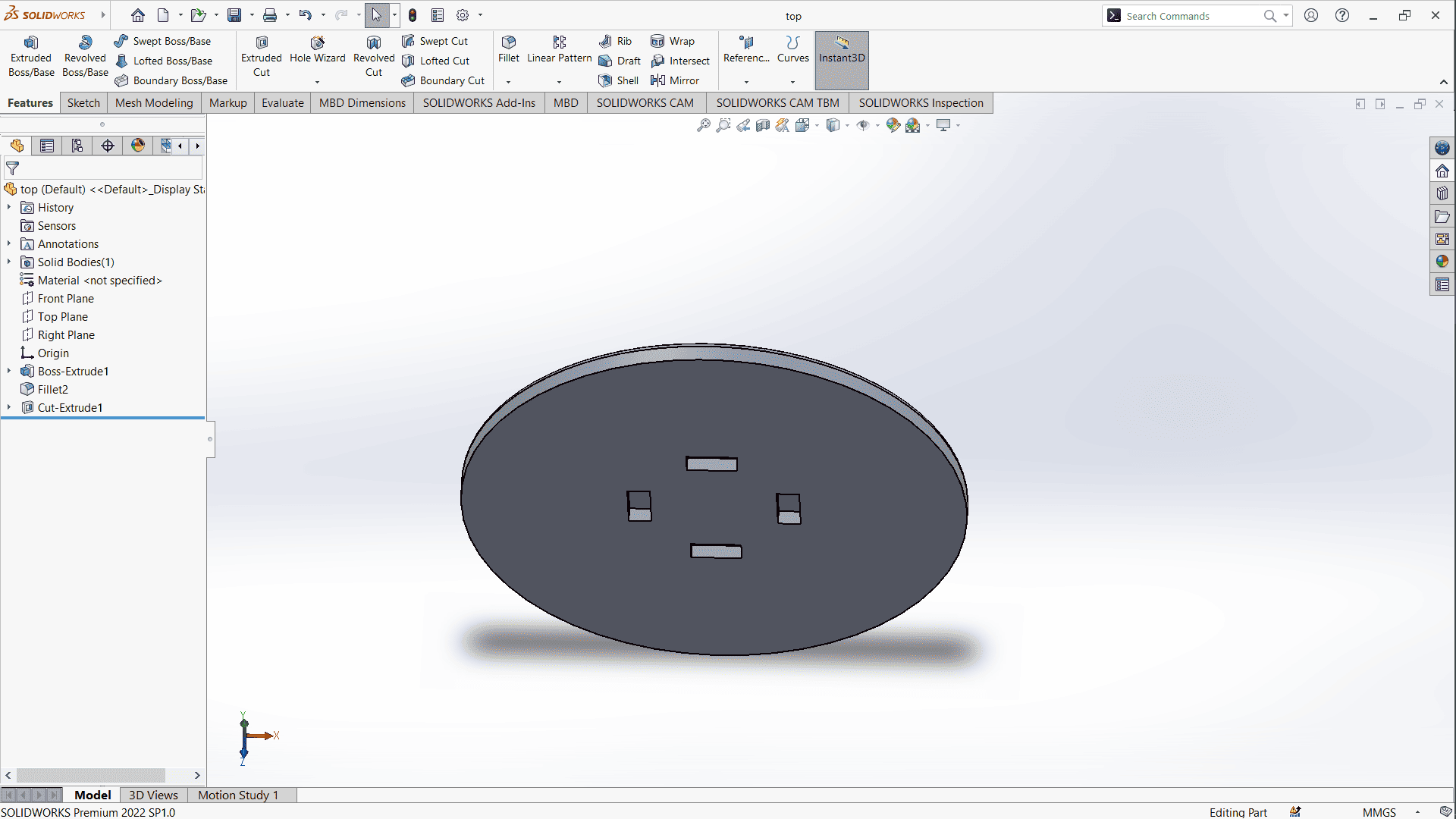
I sketched a 40 cm diameter circle and extruded it to 18 mm, matching the MDF thickness.
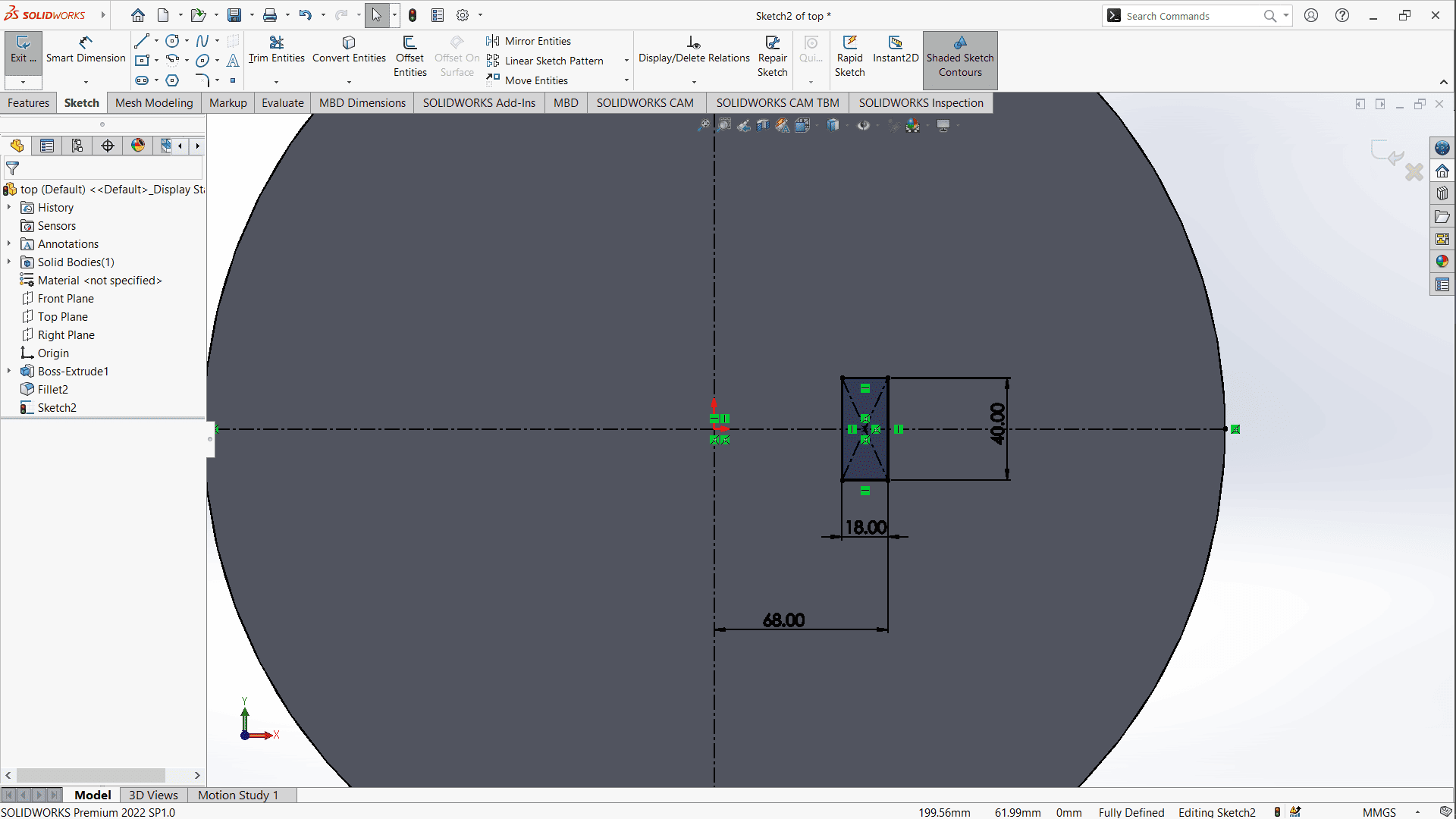
Pocketing Space for Legs:
I drew a rectangle to define the pocket area where the legs would fit.
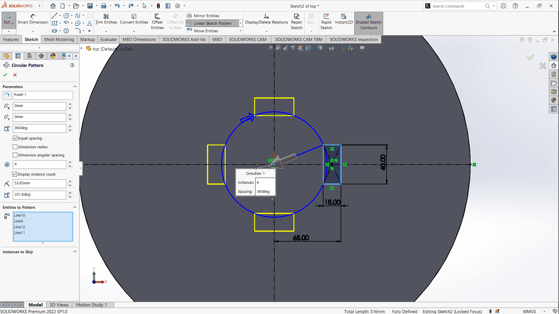
Using a circular pattern, I duplicated the pocketing rectangles around the center.
Then, I applied an extruded cut to create the actual pockets.
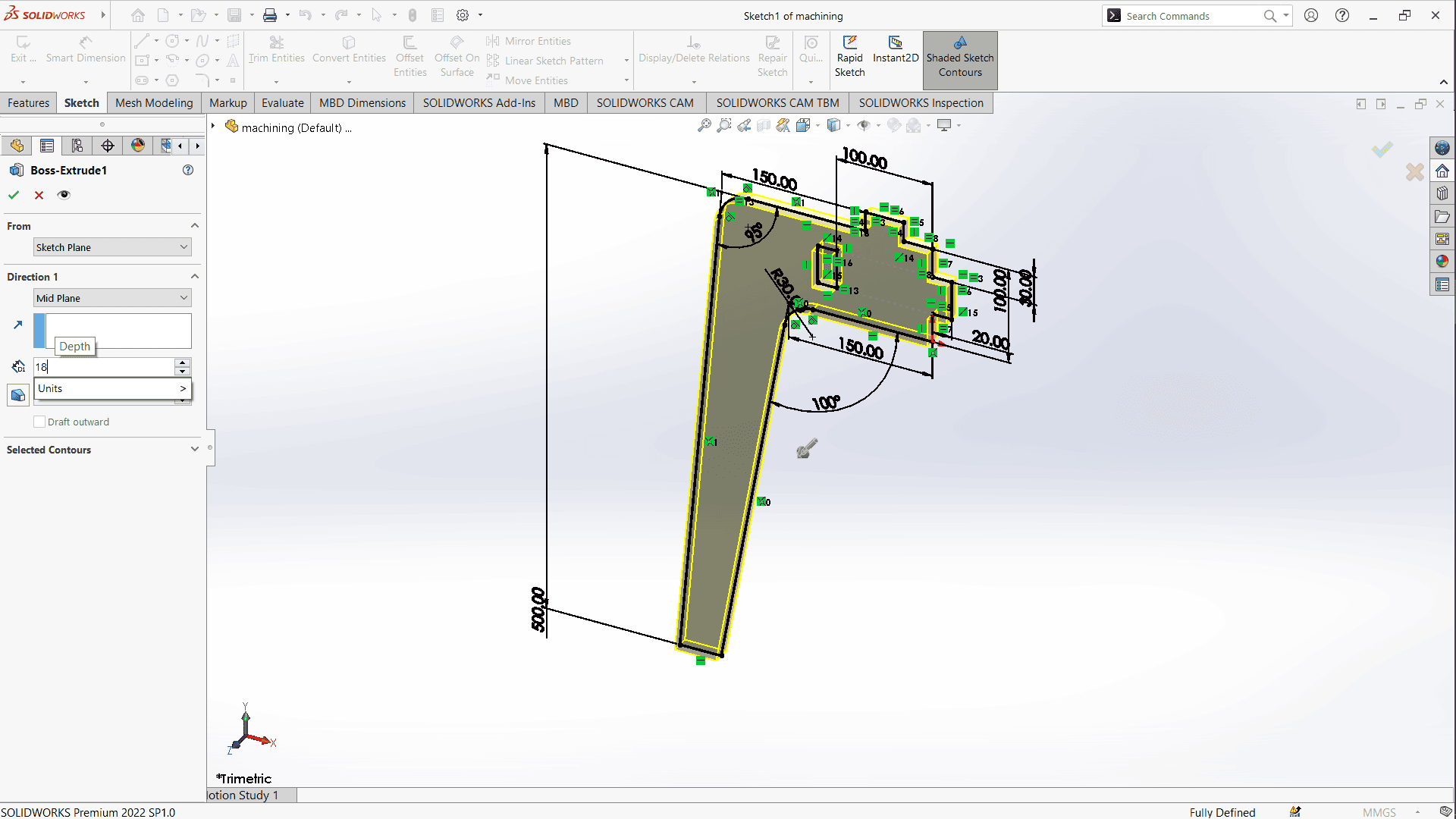
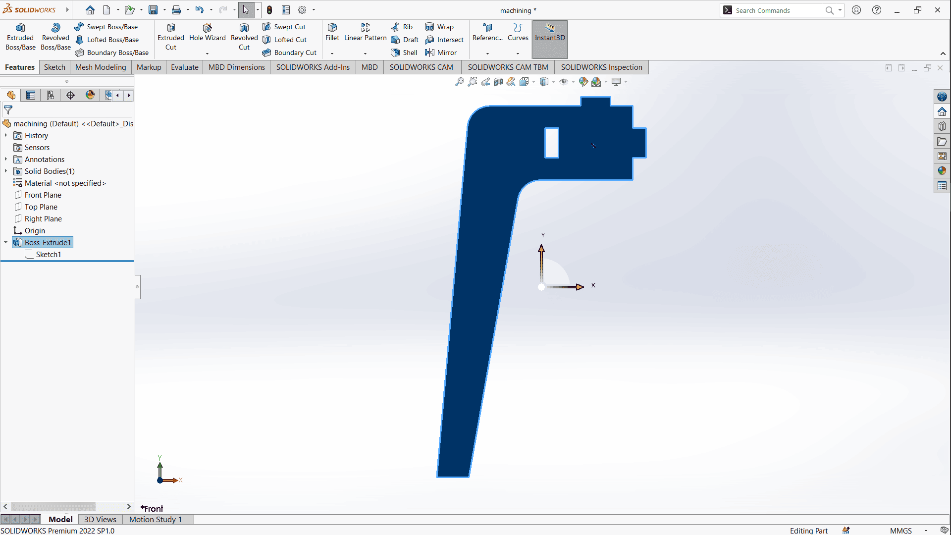
Leg Part:
I used the line and fillet tools to sketch the leg profile and extruded it to 18 mm.
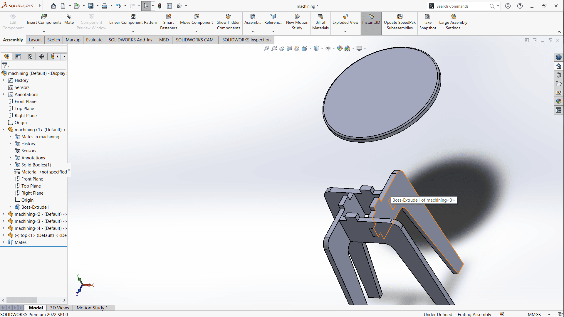
Assembly Design
In the assembly part in SolidWorks:
I imported both the top and leg parts.
Used coincident mates to connect the components properly.
Duplicated the leg part to make the 4 required legs.
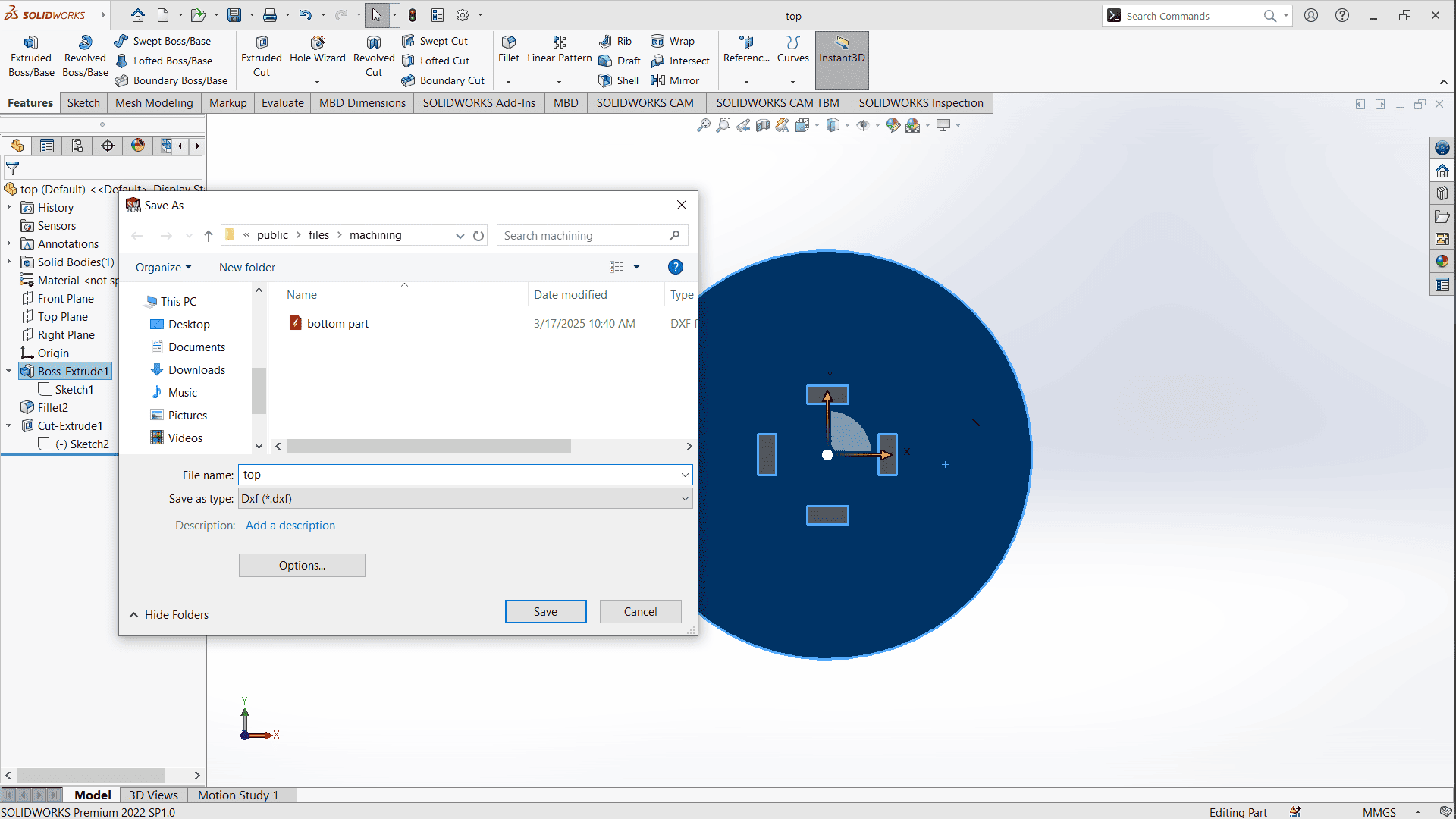
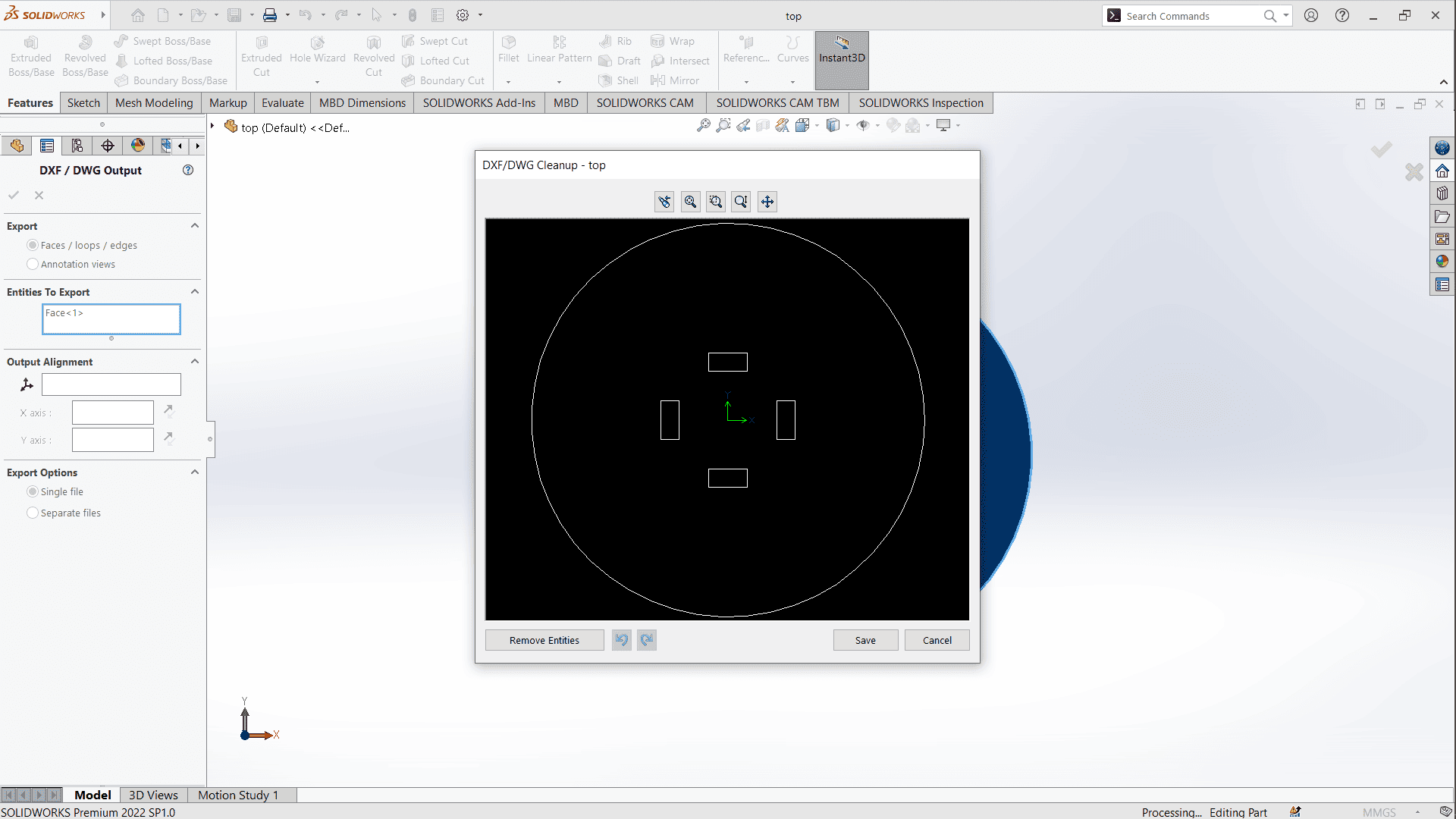
Exporting parts
I returned to the part files and exported the top and leg parts as DXF files for CNC preparation.
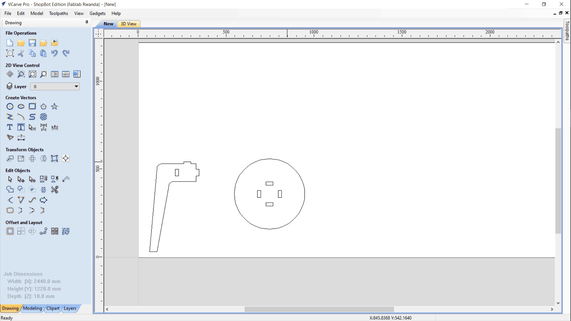
Preparing parts for cut (Vcarve)
After exporting the dxf file, I moved to vcarve to place the parts, create toolpaths and generate gcode.
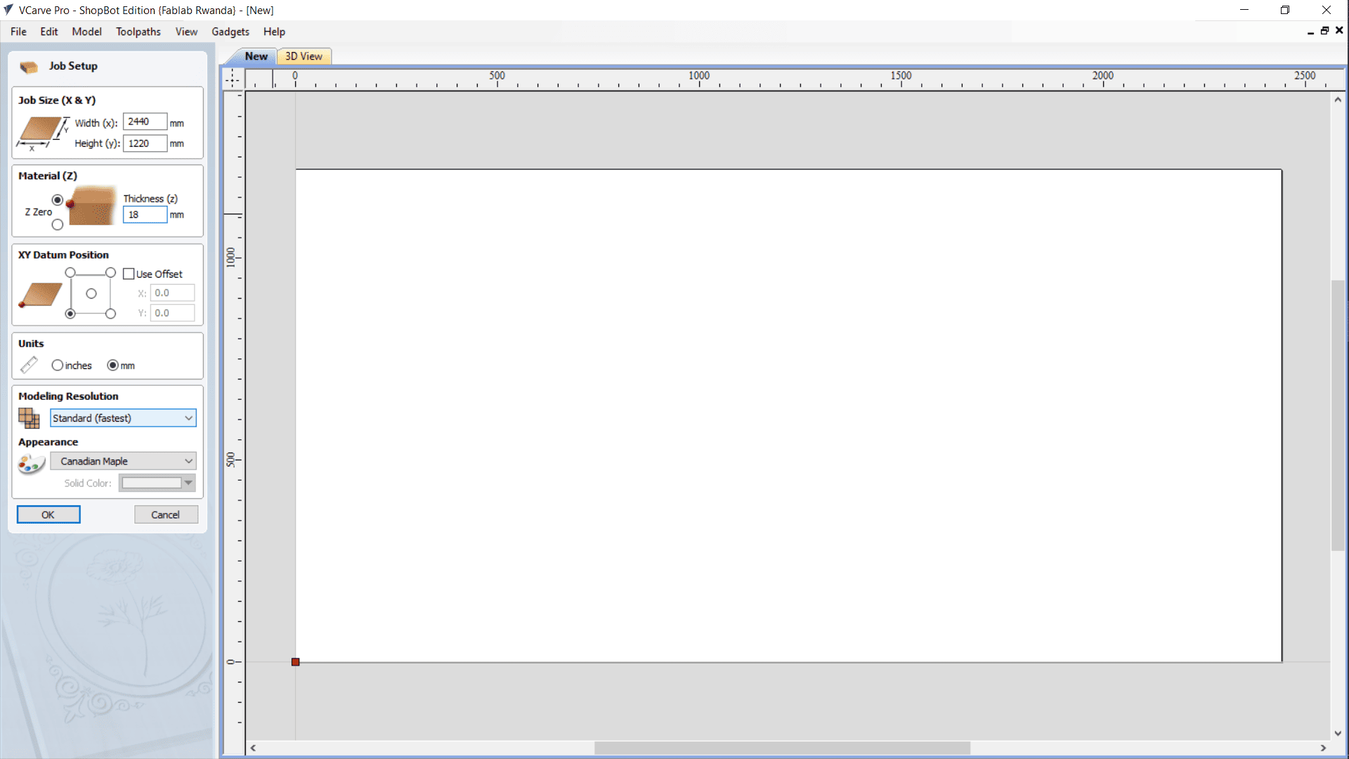
Job Setup:
I defined the full MDF board dimensions, since I was working with a fresh sheet.
I imported the DXF files for both top and leg parts.
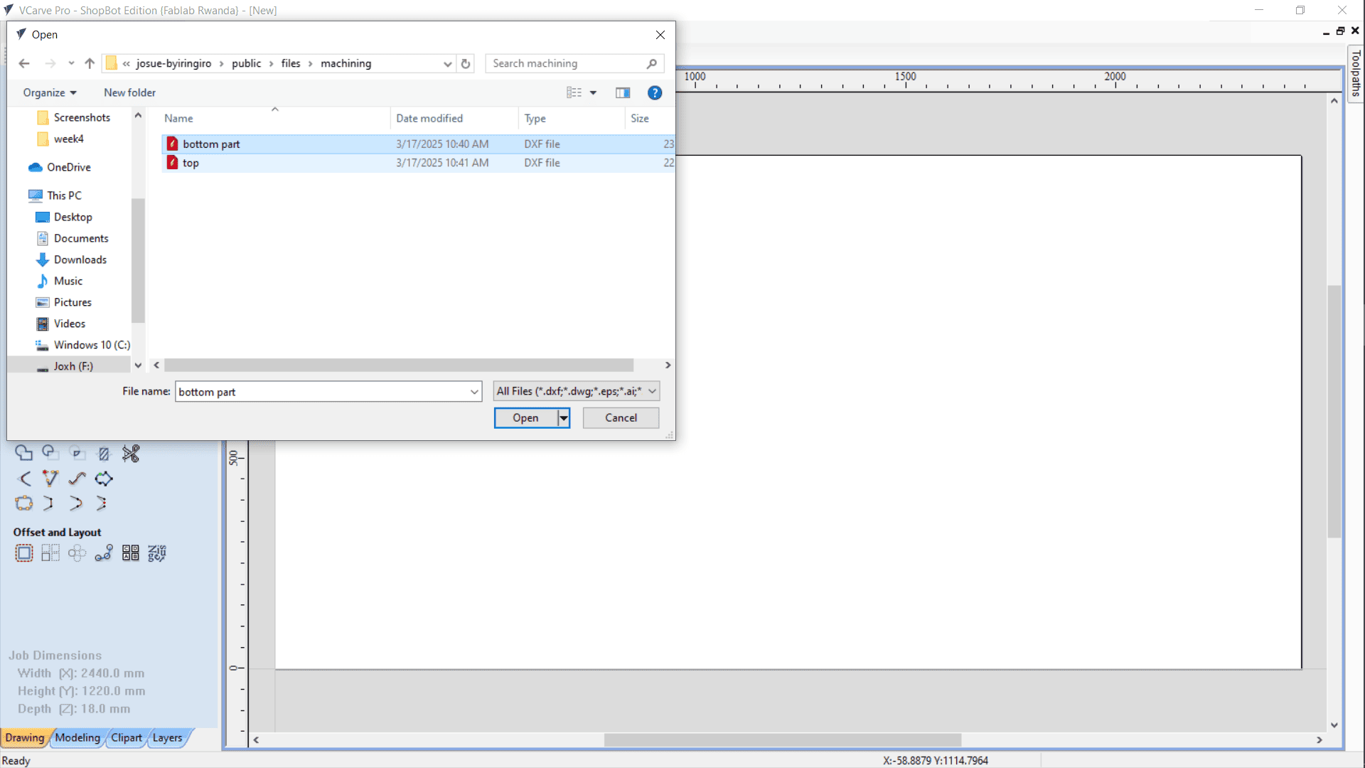
Used the Linear Array Copy tool to generate 4 leg parts.
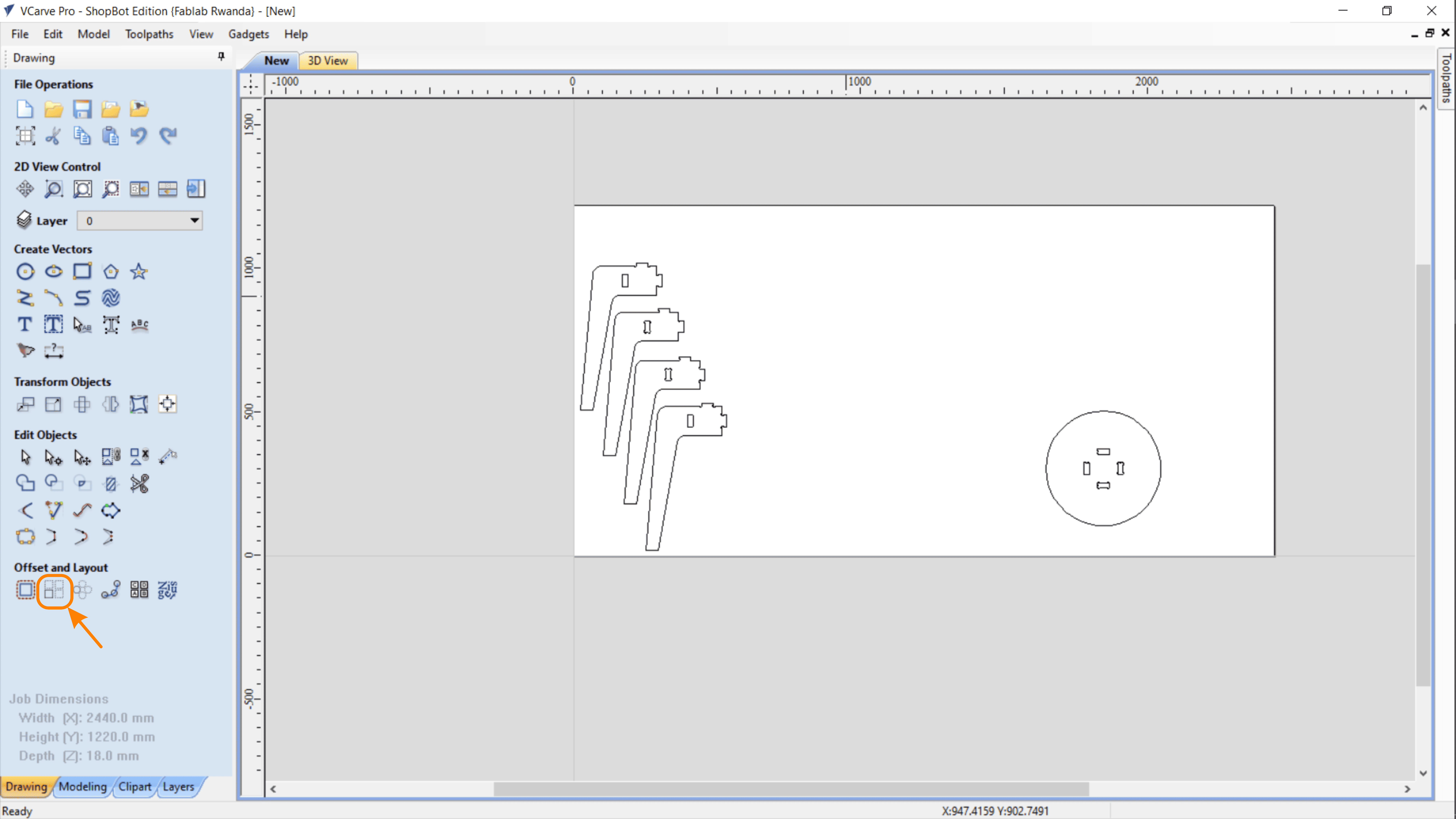
Material Optimization:
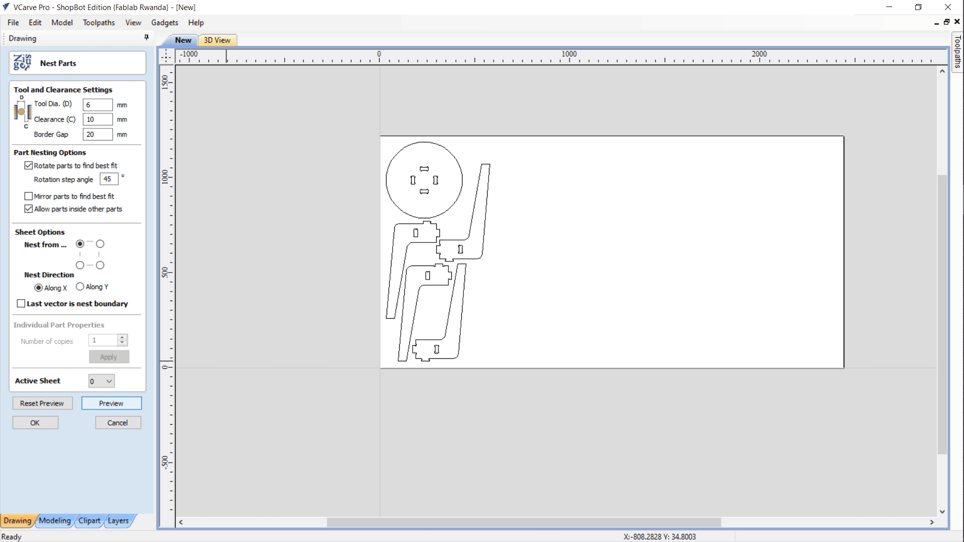
To reduce waste, I applied Nest Selected Objects.
This required:
Specifying Tool Diameter to ensure enough clearance
Adding Object Clearance to avoid tool collision
Setting a Border Gap to prevent cutting near material edges
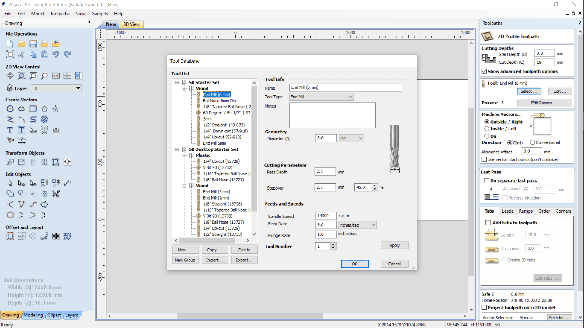
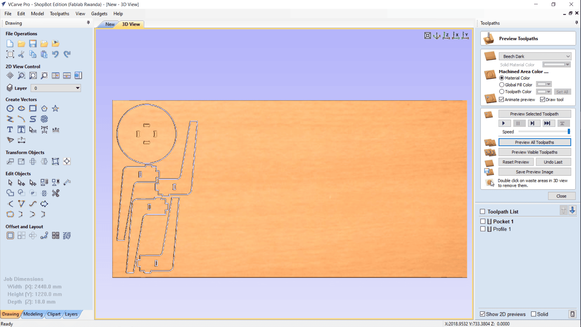
Toolpath Generation
I created two toolpaths:
Pocket Toolpath: For the slots where legs will be inserted
Profile Toolpath: For cutting out the stool parts
I selected tools and assigned proper speeds: Spindle speed, Feed rate, Plunge rate
Added:
Ramp for smoother tool entry
Tabsto keep parts in place during the cut
After reviewing everything, I ensured the toolpaths were safe and efficient.
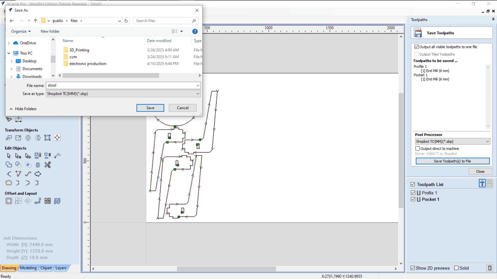
Generating G-code
I saved the toolpaths using the ShopBot post-processor to generate G-code files.
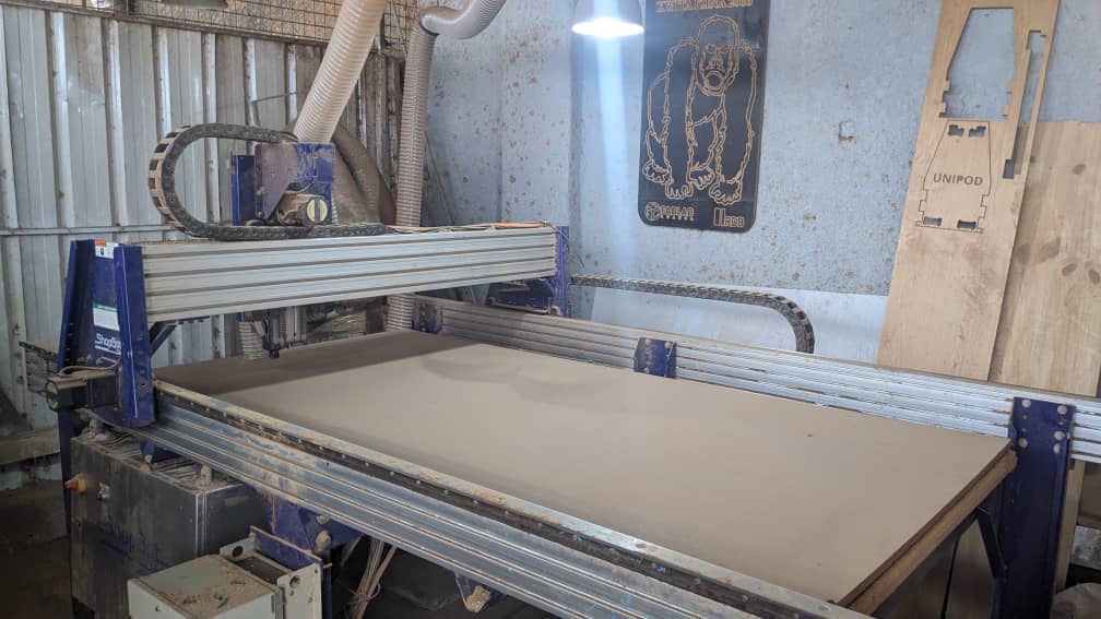
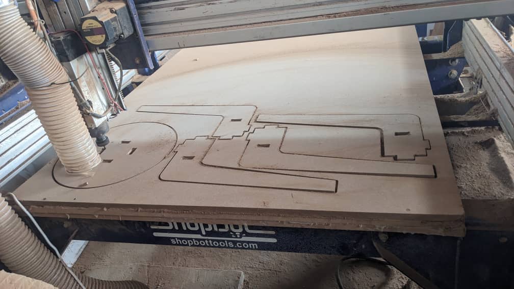
Machining the parts
On the ShopBot, I secured the MDF board on the machine bed
Installed a 6mm end mill
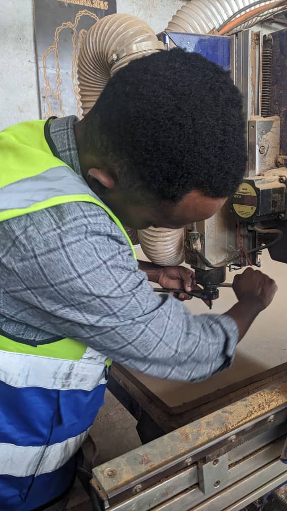
Set the machine origin and loaded G-code files into SB3 (ShopBot controller)
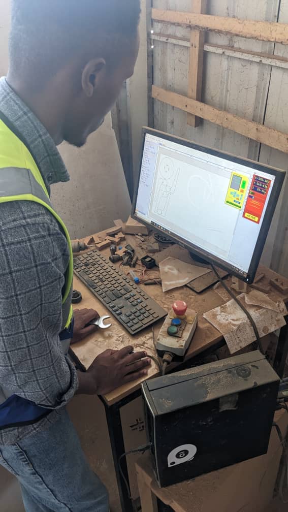
Turned on the vacuum collector and started cutting.
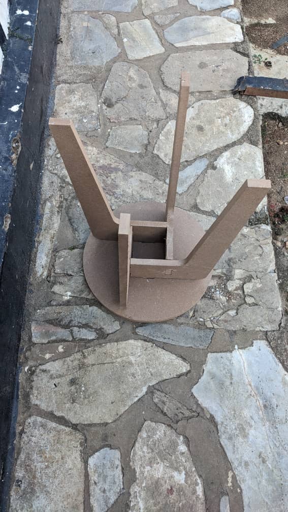
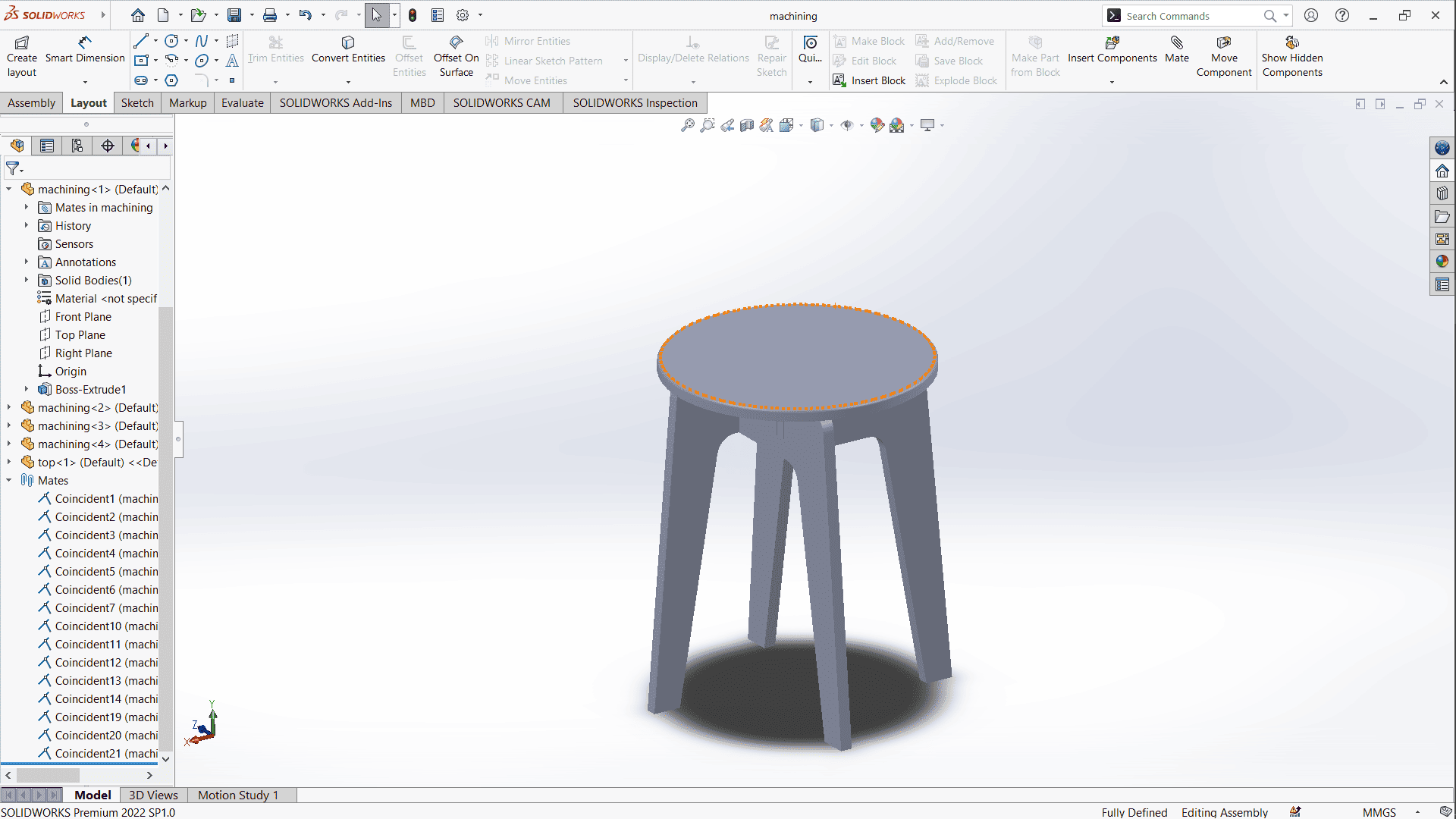
Finishing and Assembly
After machining, I assembled all the parts. The components fit together as planned, resulting in a functional and neat stool-table.