The requirement of this group assignment is to probe an input device's analog levels and digital signals. The team is expected to document their work on the group work page, showcasing the process and results. Additionally, each individual is required to reflect on their personal page about what they learned during the assignment.
Input devices are hardware components that allow users to input data and control signals into a computer or other electronic devices. They serve as the primary means of interaction between users and machines, enabling the transfer of information and commands. Common examples of input devices include keyboards, mice, touchscreens, scanners, microphones, and cameras. These devices convert user actions or physical phenomena into digital signals that the computer can process, facilitating tasks such as data entry, navigation, and communication.
The input devices stated above are made up of much more discrete and low-level sensors such as simple buttons, potentiometers, and switches. These sensors are often combined with microcontrollers or other processing units to interpret the input signals and convert them into meaningful data. For example, a button press can be used to trigger an action, while a potentiometer can measure variable resistance to control parameters like volume or brightness. These basic components form the building blocks of more complex input devices, enabling a wide range of applications in fields such as robotics, automation, and user interface design.
Input devices can be categorized into various types based on their functionality and the nature of the data they capture. Here are some common types of input devices:
Input devices can be broadly categorized into passive and active sensors. Passive sensors do not require an external power source to operate; they rely on the energy from the measured signal itself. Examples of passive sensors include thermocouples, which generate a voltage based on temperature differences, and piezoelectric sensors, which produce an electric charge in response to mechanical stress.
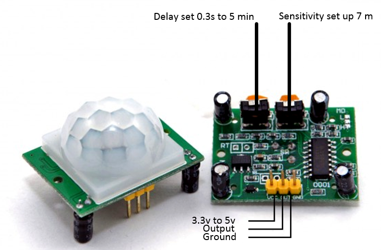
The PIR-Sensor is an exaple of a passive sensor
On the other hand, active sensors require an external power source to function. These sensors actively send out a signal and measure the response. Examples of active sensors include ultrasonic sensors, which emit sound waves and measure the time it takes for the echo to return, and infrared sensors, which emit and detect infrared radiation.
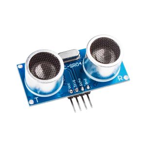
The ultrasonic distance sensor is an expample of an active sensor/input
Analog and digital inputs are another way to classify input devices. Analog inputs are continuous signals that can take any value within a range. These inputs are typically used to measure physical quantities such as temperature, light intensity, or sound levels. Examples of analog sensors include potentiometers, which measure variable resistance, and light-dependent resistors (LDRs), which change resistance based on light intensity. Digital inputs, on the other hand, are discrete signals that have only two states: on or off (1 or 0). These inputs are used for binary operations such as detecting the presence or absence of an object. Examples of digital sensors include push buttons, which detect a press or release, and limit switches, which indicate whether a mechanical part has reached a specific position.
Below is a picture showing the common types of sensors available.
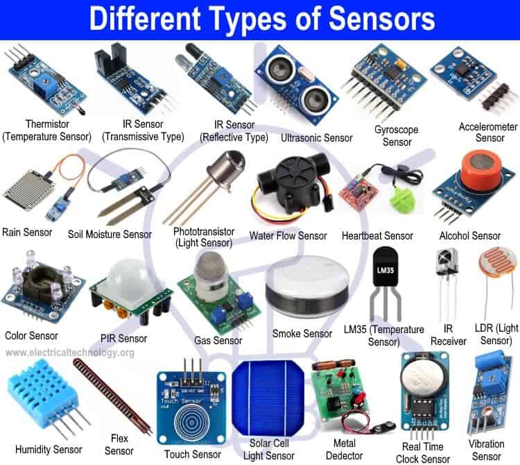
Source: electrricaltechnology.org
For this assignment, we decided to probe one analog input device and one digital input device to explore the differences in how they function and process signals. The devices we selected are:
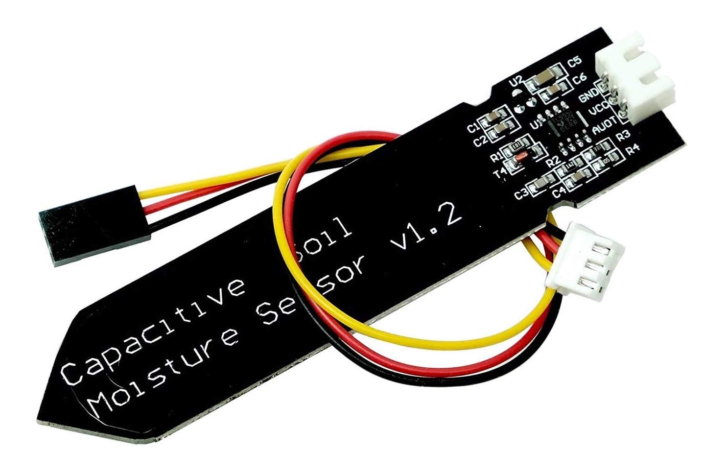
Capacitive Soil Moisture Sensor
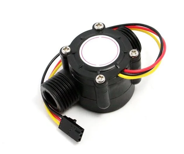
Water Flow Sensor
By working with these two types of sensors, we were able to gain hands-on experience with both analog and digital input devices, understanding their unique characteristics and how they can be integrated into electronic systems.
To analyze the signal from the Capacitive Soil Moisture Sensor, we used a visual persistence oscilloscope. This tool allowed us to observe the real-time behavior of the analog signal generated by the sensor. The oscilloscope displayed the voltage variations over time, providing a clear visualization of how the sensor's output responded to changes in soil moisture levels.
Video: Testing the Capacitive Soil Moisture Sensor
The oscilloscope provided a dynamic view of the sensor's behavior, showing smooth, continuous voltage changes as the soil moisture varied. This allowed us to identify the sensor's sensitivity and response time effectively.
To complement the oscilloscope analysis, we used a multimeter to measure the sensor's output voltage. The multimeter provided a static reading of the voltage at a given moment, which was useful for verifying the oscilloscope's measurements.
Video: Testing the Capacitive Soil Moisture Sensor along side a multimeter
By combining the oscilloscope and multimeter, we gained a comprehensive understanding of the Capacitive Soil Moisture Sensor's output signal, enabling us to evaluate its performance effectively.
To analyze the signal from the Water Flow Sensor, we used a digital oscilloscope. This tool allowed us to observe the digital pulses generated by the sensor as water flowed through it. Each pulse corresponded to a specific volume of water, providing a clear representation of the flow rate.
Video: Testing the Water Flow Sensor with a Digital Oscilloscope
Video: Testing the Water Flow Sensor with a Digital Oscilloscope
By using the digital oscilloscope, we were able to analyze the behavior of the Water Flow Sensor in detail, gaining insights into its performance and how it translates water flow into digital signals.
Reflecting on our experiments, we observed the distinct advantages and limitations of using a digital oscilloscope and a multimeter for analyzing sensor signals. The digital oscilloscope proved invaluable for understanding the dynamic behavior of both analog and digital signals. For the Capacitive Soil Moisture Sensor, the oscilloscope allowed us to visualize how the analog signal changed over time as we moved the sensor in and out of water. This real-time visualization provided insights into the sensor's response time, sensitivity, and noise characteristics, which would have been impossible to observe with a multimeter. The multimeter, while useful for static voltage readings, lacked the ability to show these time-dependent variations, making it less effective for analyzing the continuous nature of analog signals.
On the other hand, the multimeter was easier to use for quick and straightforward measurements of analog signals. Its simplicity made it ideal for obtaining a single voltage value at a specific moment, which can be sufficient for basic testing or calibration. However, this simplicity came at the cost of losing the detailed temporal information that the oscilloscope provided.
For the Water Flow Sensor, the oscilloscope's ability to capture high-frequency digital pulses was critical. As we blew air into the sensor at varying speeds, the oscilloscope displayed the changes in pulse frequency, giving us a clear understanding of how the sensor's output correlated with the flow rate. The multimeter, in contrast, was unable to capture these rapid changes, as it is not designed to measure high-frequency digital signals. This limitation highlighted the importance of using an oscilloscope for analyzing digital signals, especially when dealing with fast-changing or high-frequency data.
These observations have significant implications when processing sensor signals with a microcontroller. For analog sensors like the Capacitive Soil Moisture Sensor, the microcontroller must sample the signal at an appropriate rate to capture meaningful data without missing important variations. For digital sensors like the Water Flow Sensor, the microcontroller must be capable of accurately detecting and counting high-frequency pulses to calculate the flow rate. Understanding the behavior of these sensors through tools like oscilloscopes ensures that the microcontroller's sampling and processing capabilities are well-matched to the sensor's output characteristics, enabling reliable and accurate data acquisition.