
Week 03: Computer Controlled Cutting
This week we were taught about Computer controlled cutting, specifically laser cutting and vinyl.
The following link leads to the Fab Lab BCN page which has all the documentation we were given and taught about in class: Computer Controlled Cutting Documentation
Assignment
Group Assignment:- Do your lab's safety training
- Characterize your lasercutter's focus, power, speed, rate, kerf, joint clearance and types.
- Document your work to the group work page and reflect on your individual page what you learned.
Individual assignments
- Design, lasercut, and document a parametric construction kit, accounting for the lasercutter kerf, which can be assembled in multiple ways.
- Cut something on the vinyl cutter.
Learning outcomes
- Demonstrate and describe parametric 2D modelling processes.
- Identify and explain processes involved in using the laser cutter.
- Develop, evaluate and construct a parametric construction kit.
- Identify and explain processes involved in using the vinyl cutter.
Have you answered these questions?
- Linked to the group assignment page.
- Explained how you created your parametric design.
- Documented how you made your press-fit construction kit.
- Documented how you made something with the vinyl cutter.
- Included your original design files.
- Included hero shots of your results.
Lab Safety Training with Josep
Josep took us to the laser cutting room and introduced generally to the machines and safety protocols to watch out for. We were introduced to the Chinese made R400
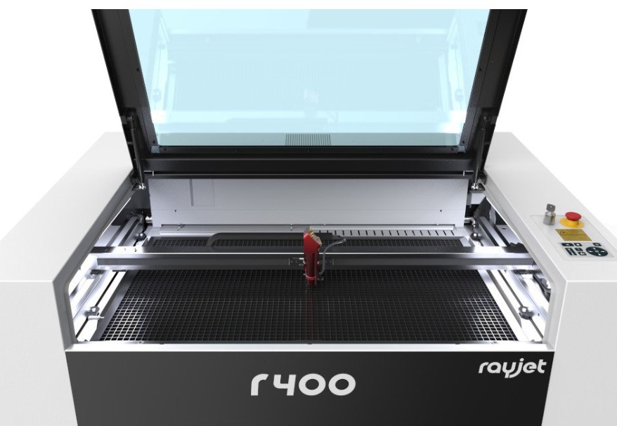
(Source: FabLab BCN Documentation: https://fablabbcn-projects.gitlab.io/learning/educational-docs/fabacademy/classes/03-Computer-controlledCutting/ )
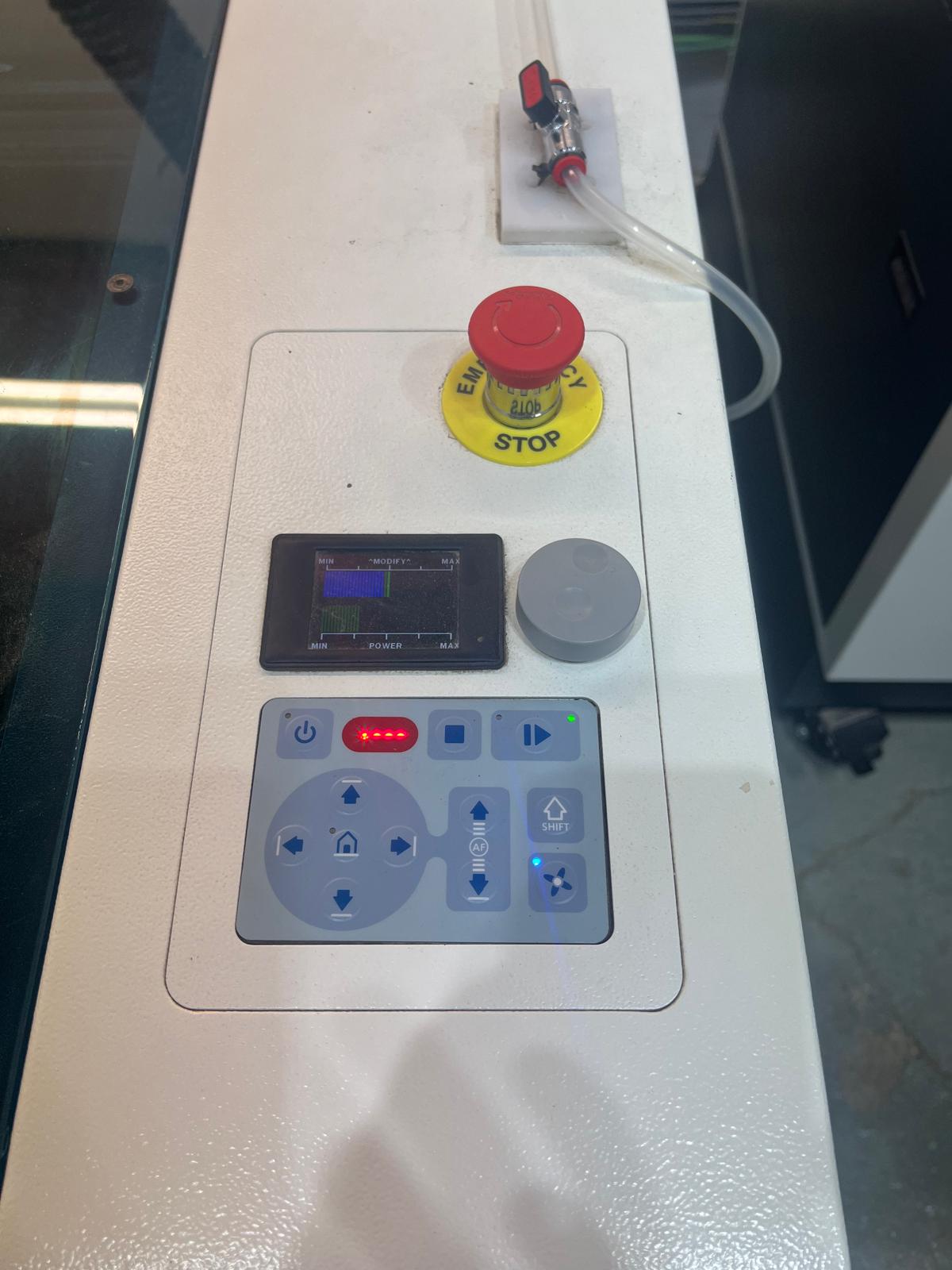
Of the four rules I remember, the first was to ensure proper ventilation in the room overall by making sure the air extraction system is on to make sure there is no build-up of harmful fumes. The second is to check & set the focus gauge before cutting. It is a little tool in a box on the right of the R400 Trotec laser cutter which is balanced on the laser. We then move the bed of the laser up to meet the laser until the gauge touches the bed (it will fall over when that happens). We do this to make sure that the laser is focused at the correct height. The next issue to be aware of before cutting begins is switching on the air assist mechanism which will blow air inside the laser onto the cutting area to keep the laser lens clean and the area from setting on fire. To switch it on, one turns a little knob on the right hand of the machine where a clear tube can be seen. When it's switched on there should be a hissing noise which is the flow of air. Finally, once the printing begins, never leave the machine unattended while it is still operating as fires do happen. If there is an issue, first press the pause button, if it looks like there is no fire one can resume by unpausing, otherwise the big red stop button should be hit.
Other important aspects to be aware of are the materials that can and cannot be used with this machine. Always check the specific machine you are using to see what materials it can cut and what may be hazardous.
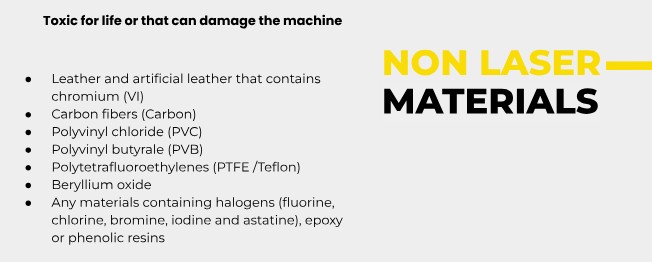
(Source: FabLab BCN Documentation: https://fablabbcn-projects.gitlab.io/learning/educational-docs/fabacademy/classes/03-Computer-controlledCutting/ )
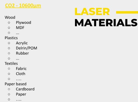
(Source: FabLab BCN Documentation: https://fablabbcn-projects.gitlab.io/learning/educational-docs/fabacademy/classes/03-Computer-controlledCutting/ )
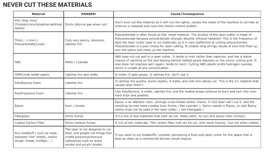
(Source: FabLab BCN Documentation: https://fablabbcn-projects.gitlab.io/learning/educational-docs/fabacademy/classes/03-Computer-controlledCutting/ )
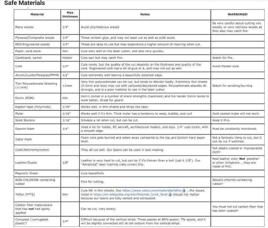
(Source: FabLab BCN Documentation: https://fablabbcn-projects.gitlab.io/learning/educational-docs/fabacademy/classes/03-Computer-controlledCutting/ )
Theory
My understanding of laser parameter settings and terms:
- Power: This is your laser's muscle. The more power, the deeper cuts or darker engravings which are useful for tougher materials (wood) but might be too much for paper or acrylic. Less power is good for more delicate engravings.
- Speed: The faster the laser moves around, the quicker it finishes the job. However, if its too quick and there won't be enough time to cut through materials well enough and vice versa.
- PPI (Pulses Per Inch): This is like a detail button. A high PPI means more pulses per inch which means super smooth finishes but it takes longer. When the PPI is set lower, the work is faster but details are less smooth which is ok for text or simple shapes. (I read that PPI should match the DPI of an image).
- Frequency (Hz): is the pulse rhythm of the laser during cutting. A higher frequency (5,000–20,000 Hz) of rapid pulses gives glassy-smooth edges on acrylic and is better for display pieces. A lower frequency (1,000 Hz) might be better for wood.
- Passes: means how many times the laser over the same spot. The more passes means you are doing more repetions and less passes are less repetitions. Ideally one pass would be perfect.
- Air Assist: should be kept on to blow away smoke from the lens. It reduces scorch marks, and protects the lens. It stops wood or acrylic from going on fire.
- Z-Offset: is the focus of the laser. Defocus Spreads the beam for even coverage on big engravings or for a melting effect, and a tight focus sharpens the beam for precision cuts or tiny details.
Comments on the Group Assignment
Conceptually I understand what needs to be done for this exercise. The group assignment where we had to characterise the laser's Kerf, focus, power and speed is designed to give us an understanding of how to understand any equipment that we come across in the future and how these parameters can impact the laser cutting.
Our group assignment page can be found here, but I wanted to discuss what was most important to me from that group assignment. So, that was the Kerf. This is the "width" of the material removed by the laser beam during cutting. The Kerf depends on factors such as the laser type, the material thickness (i.e. cardboard, plywood etc), and focal settings. We saw that other groups had taken solar callipers
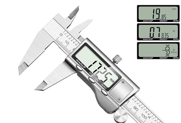
(Source: FabLab BCN Documentation: https://fablabbcn-projects.gitlab.io/learning/educational-docs/fabacademy/classes/03-Computer-controlledCutting/ )
to measure the material first. In our case the thickness was 4.7mm, and then we decided to create a 'comb'. Instead of equal sized teeth, we would make the first tooth at the width of the material i.e. 4.7mm, and then decrease each tooth size by 0.05mm. We reduced it by 4.35mm but our results revealed that this was too optimistic. We tried it the following day and found that for our cardboard test comb, somewhere around 0.9mm to 1mm worked better and would allow the comb to hold the cardboard in a snug enough manner. So, the Kerf of 1mm means we would have to alter our drawings to reflect a narrower tab and slot widths.
Once we have done this we then make a CAD file for each different material, since each material has a different thickness and the laser will have a differing effect on other materials such as acrylic or plywood Vs cardboard. We then upload it to the Fab Cloud and then bring it into the laser machine software Rayjet Manager. We do two things simultaneously. We prepare the file, set the material thickness and speed and power settings, as well as placing material inside the printer and flattening it with tape and clips if necessary. We focus the lens using the measurement gauge, place the laser at the starting point, close the lid and start our air compression on as well as air extraction.
We put in a test a square and if the cutting/engraving works we start cutting our design. Unfortunately, I am very weak still designing anything on CAD software and don't have the confidence and understanding that come from putting in hours of learning. I am going through videos on Fusion 360, Inkscape, Rhino/Grasshopper, Blender and Blender Nodes but it takes time. It's a question of time. At this stage, little things in the tutorials confuse me and take time and the following day forgotten again. I can already tell that I will have to redo the tutorials once I am finished. Since I have already decided on my final project, a technological lamp, I will be trying to create a lamp shape in all these software's when I find the right tutorials.
I understood all the concepts but felt that I had to rely on other team members to create the comb shape, which one would think is simple! Once I am fluent enough with CAD I hope not to have such issues.
Comments on the individual assignment
Parametric Construction Kit
On Thursday we had a Fusion 360 lesson with Didac and went over a polygon shape to be used as a parametric press-fit kit. This was the first CAD class where I was able to keep up with instructions. I have a non-design/architecture/making background and so looking at the software with fresh eyes found the logic of how to draw the shape and the interface to be overly complex and unintuitive. (Side note: it is easier than Rhinoceros 3D for beginners but Rhino is necessary for all machines and so I will have to approach it soon). This will require hours of following tutorials. There are no shortcuts.
I recommend anyone attempting this course to go over Learn Fusion in 30 days tutorials TWICE as I am in the process of doing.
Some questions one may have are. What will I create? How do I know if it will all fit together? How can I know what measurements should be to make it work? Will I manage to do Kerf compensation? Will I ever be able to create my own original object? Will I be able to operate the laser software machine and put in all the parameters alone and trouble shoot?
I started looking at previous parametric press-fit kits by previous students and at online examples. I decided to copy what someone has done. It will help build confidence. Later I can be more ambitious.
I created a sketch with measurements on paper as I had not been able to create anything in Fusion 360
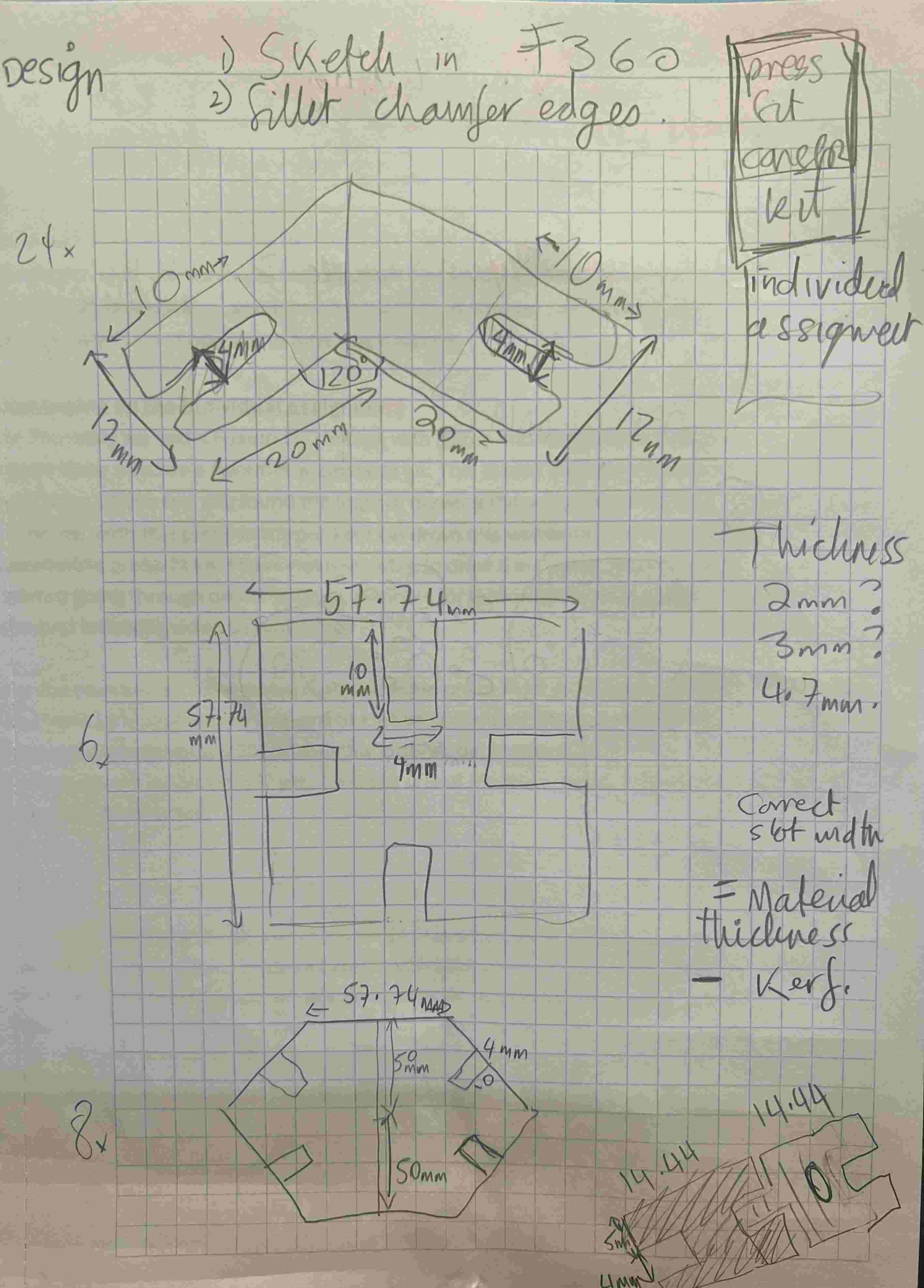
I found it on Elaine Lu's page
With some help from my classmate Andrew and the Fusion 360 guru Didac I drew the object, dimensions, extruded it.
I have recommendations. Be structured. It will save you time and make the process organised and calm. Start by deciding on all your dimensions, and create parameters for the measurements in Fusion 360

Learn about workflow & layers to make future workflow structured and calm
Also, invest some time learning about how to layer drawings and parts that you are creating in Fusion. I didn't know better when I started and my workflow became a bit of a mess which doesn't help printing, altering, documenting. As I write this, my next free moments will be spent learning about this in Fusion360 and any other software I use.
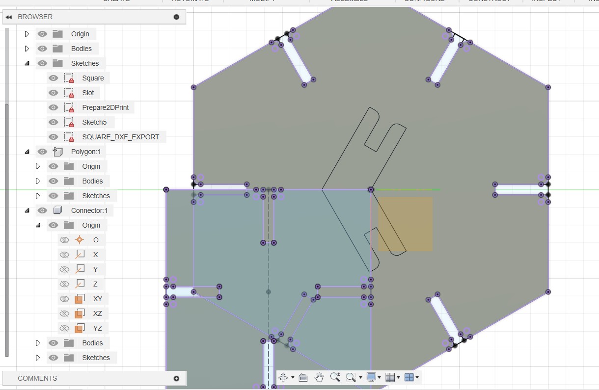
This is a drawing of my square, polygon and connector based on the aforementioned parameters:
Preparing the Fusion 360 file for printing
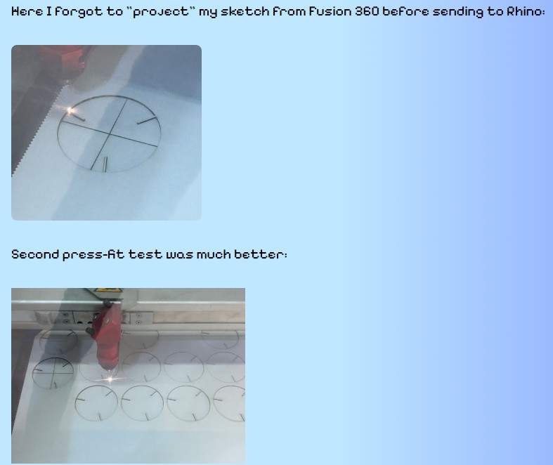
I had finished and was ecstatic. and ready to print but my classmate told me I needed to project the image before exporting it to DXF. I didn't really understand why or what it was all about. So after quite a bit of discussion with chatgpt, I understood that If you don't project the top view sketch before exporting, then all the construction lines, extra geometry, and hidden edges inside and underneath your model might also be included in the exported file.
What happens if you forget to project the design
I found an example of what could happen to a laser cut if one forgets to project from a former Fablab Barcelona student Carolina Fernandez
Rhino Project Setup
So, in Fusion 360 we to project we click Create Sketch, then Create menu and Project/Include or CTRL+P. Then click on the edges to be projected and they will turn purple. After that click Finish Sketch, and Right-click the relevant sketch in the Browser Panel on the left. Select Export as DXF.
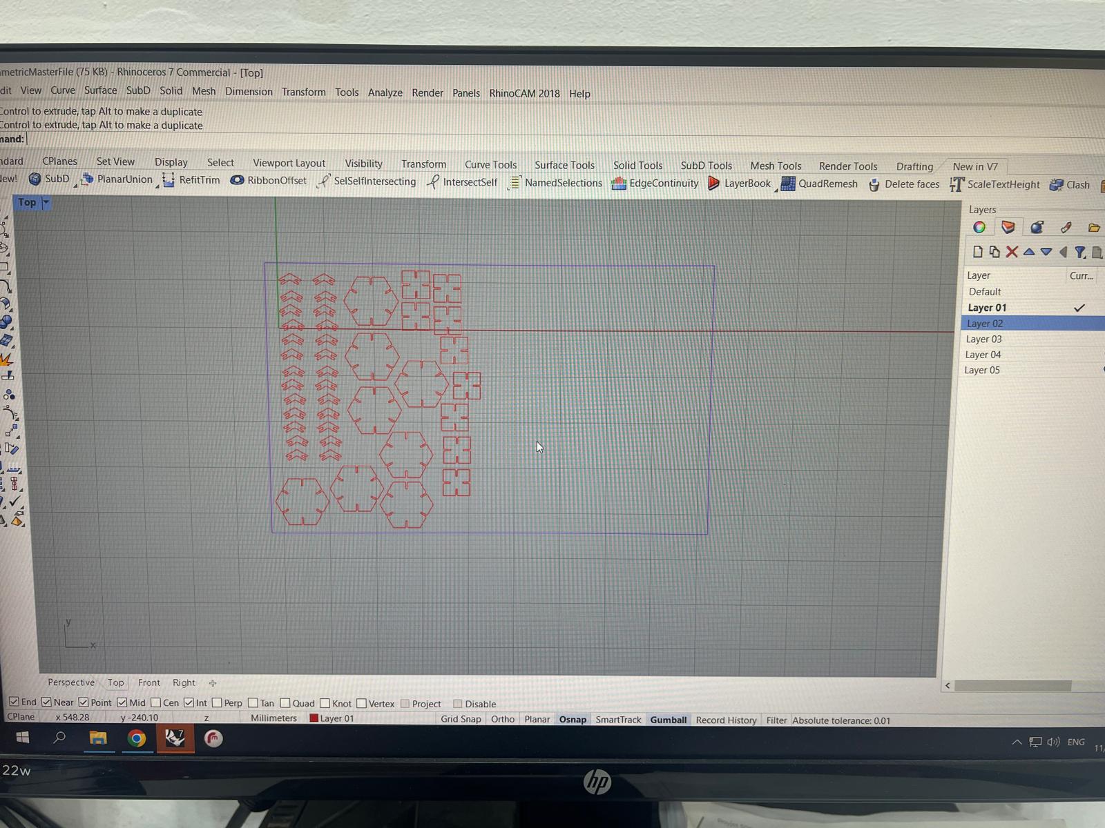
I then opened the DXF File in Rhino, took out the extra lines which are created when saving from Fusion360. You know they are extra because when they are selected they turn pink. The quick way to delete all extra lines if you have many objects is using the SelDup command in Rhino. It highlights the extra lines and then one can click delete.
Project Setup (continued)
To prepare the desired layer we highlight the desired objects to move to that layer, and then over the intended Layer right click and Change Object Layer. To doublecheck it worked, turn off other layers and all the objects to print should still be visible in the canvas.
Some people may skip steps, but It is considered a best practice to create layers to help differentiate between what one is cutting, engraving, marking or perhaps what pieces are internal and external. The point is, a clean and structured workflow is very important and will actually speed you up. I am the weakest in terms of experience, skill sets but following the steps I was shown helped me to finish earlier and more calmly than expected.
You can download the Parametric Master File here: Week03PressFitDrawingv12.f3d, Week03ParametricMasterFile.3dm
Finally save the print file to https://cloud.iaac.net:5001/ as you will need to access your file in the laser room.
Laser Cutting Process
Measure the material you will be cutting with, i.e. 95cms x 58cms
Open your file from the cloud in Rhino on the computer which corresponds to the Laser that you will be using.
Create a boundary box around the objects you are printing and make sure that the units match. So when drawing in the boundary box, in my case it was 9500 x 5800 which is in mm and matches the objects in my Rhino file.
In Rhino go to File/Print and Rayjet Manager automatically opens. Press the connect button which is on the bottom right corner and then the Rhino file should be visible on the right hand side in Rayjet. Drag and drop into the center canvas. Click on an eye icon to set material thickness and settings.
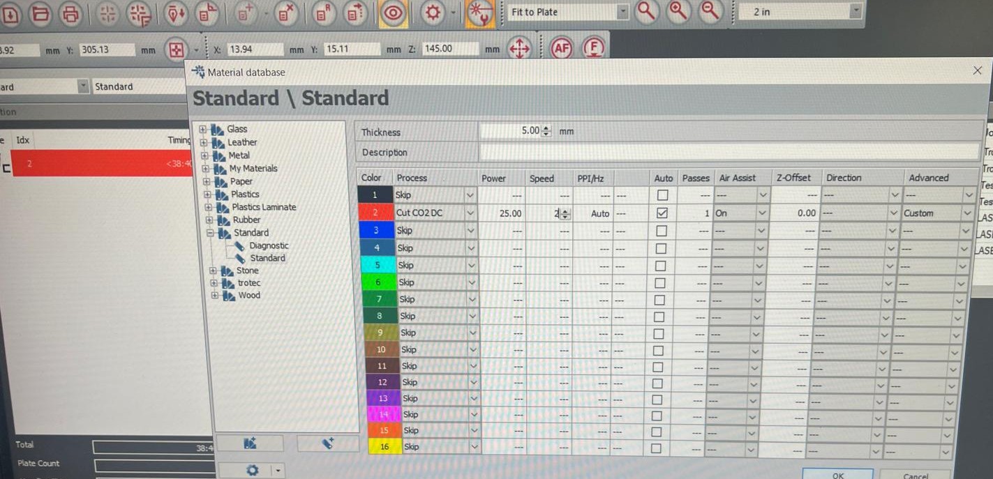
The settings are based on material thickness, Kerf and there are recommended speed and power settings for different types of materials.
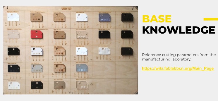
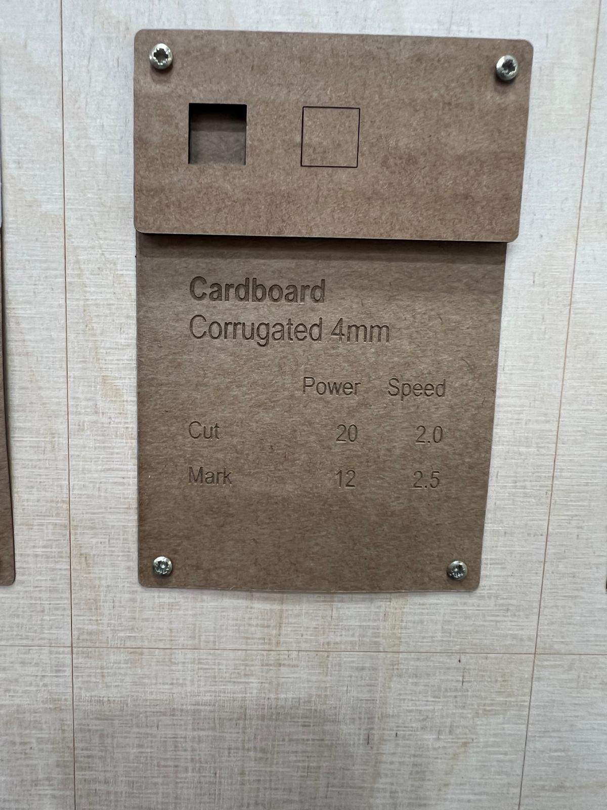
This following screenshot shows that 4mm Corrugated cardboard has a recommended Power and Speed setting of 20 and 2. In this case my cardboard was 4.7mm so I decided to increase the power setting to 25 to compensate for the extra thickness. It is recommended to print a test piece or square, but in this case I didn't as I had witnessed the group assignment and was quite confident about what would happen.
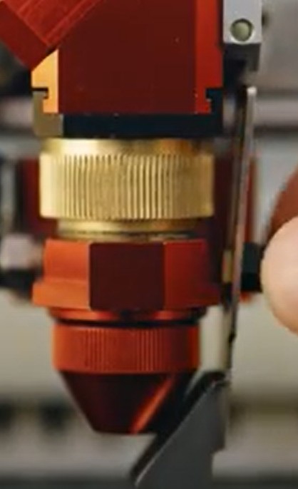
We are ready to print now and need to do some setup before we click PLAY and print out the press-fit kit. Take the transparent focus tool for the Trotec R500 or whatever machine you are using, With the Trotec R500 we put the tool underneath the laser and unscrew the laser focal point and let it come down until it reaches the 0 point of the tool. Then we tighten the lens and put the focus tool back in the box.
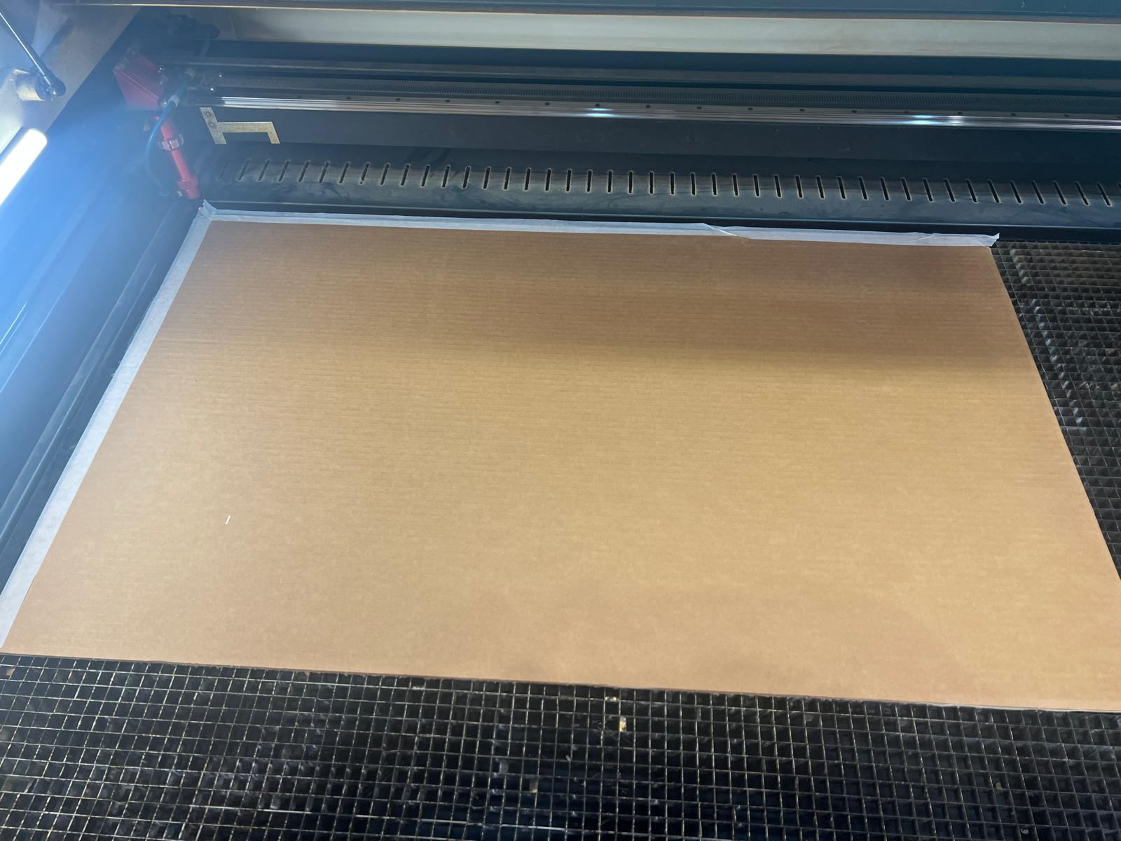
Lay down the cardboard material, tape it and clamp it down so the surface is flat. We make sure that the machine is switched on, the airflow to the laser is on, and then top is closed. Use the directional buttons on the R500 to make sure the X,Y co-ordinate of the laser printer is at the top left hand corner of the canvas to match the top left point of the border in the file you will print from.
Now, press the play button and and for safety reasons make sure you are present and paying attention. The printer is always on the edge of catching fire. If it happens (which is rare) first press pause, then one can continue. If the fire is too strong then just hit the red stop button.
Results
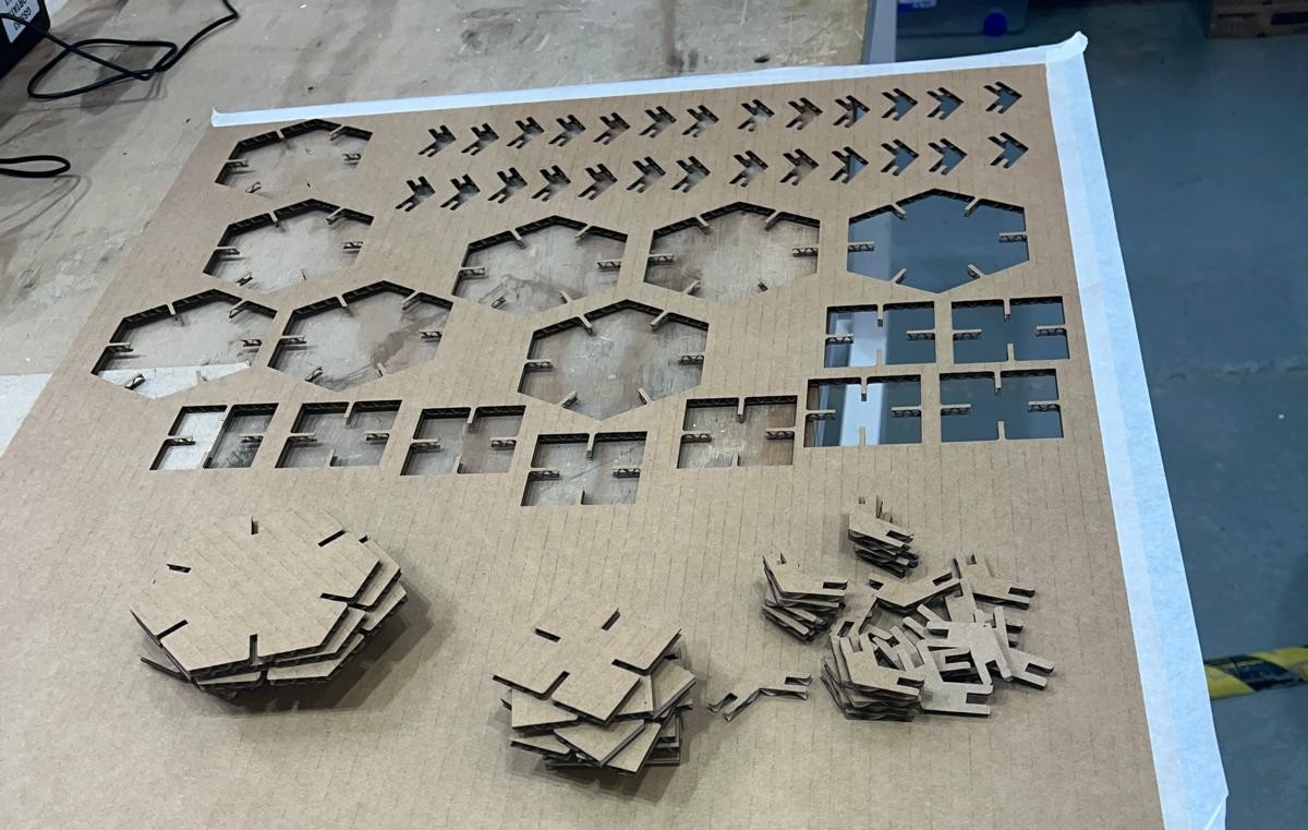
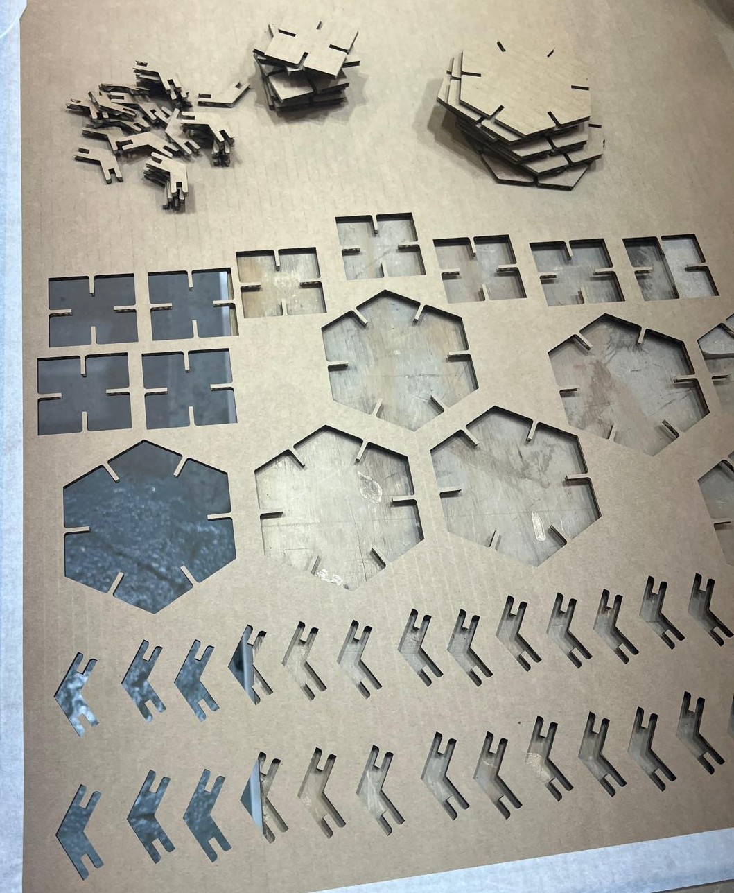
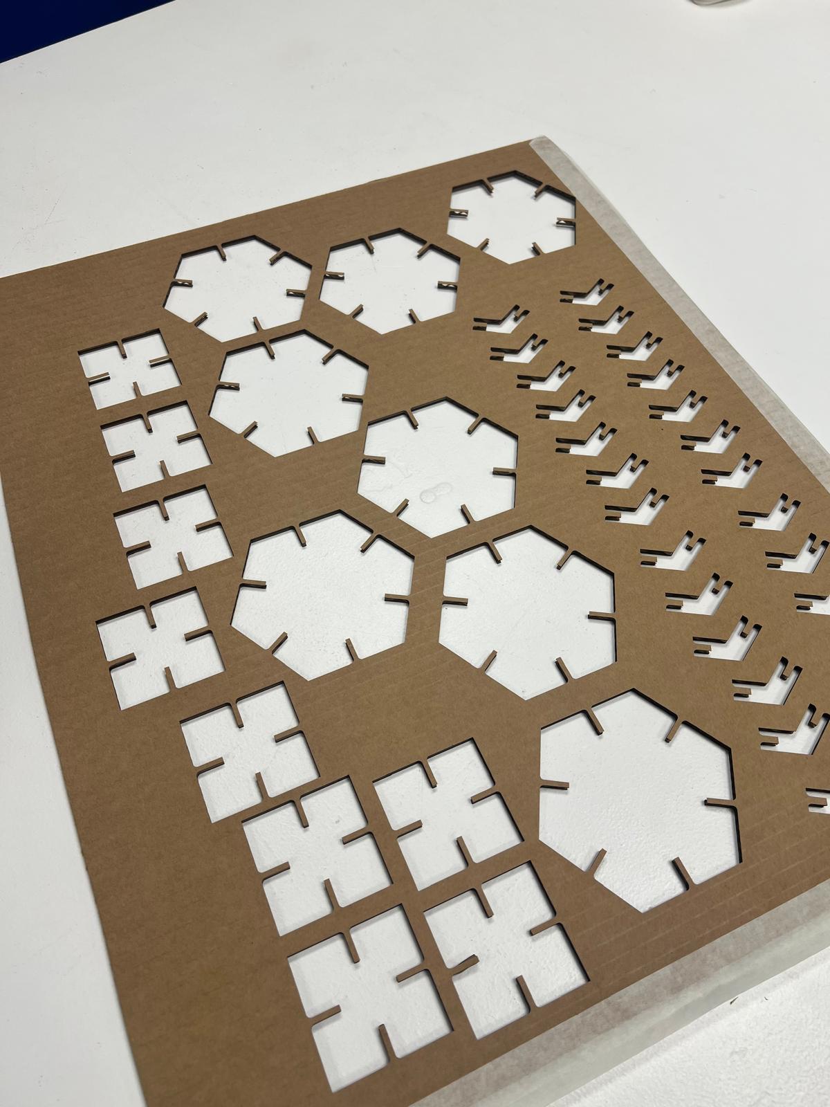
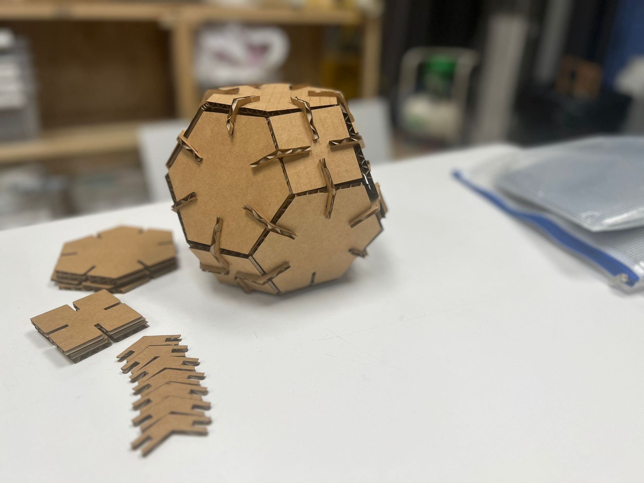
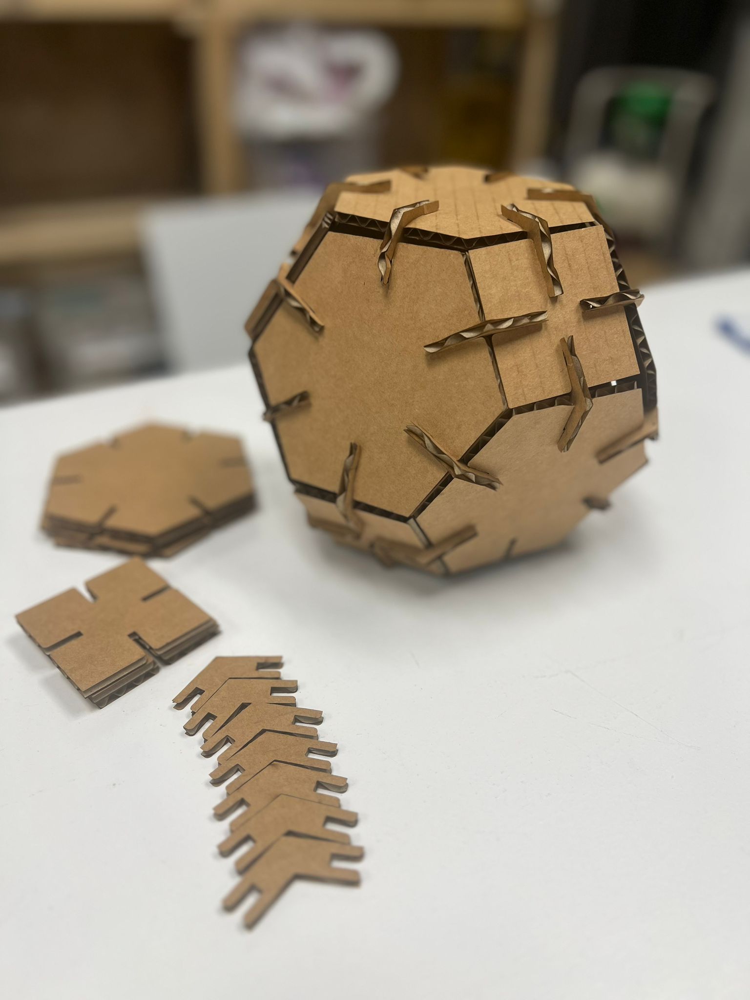
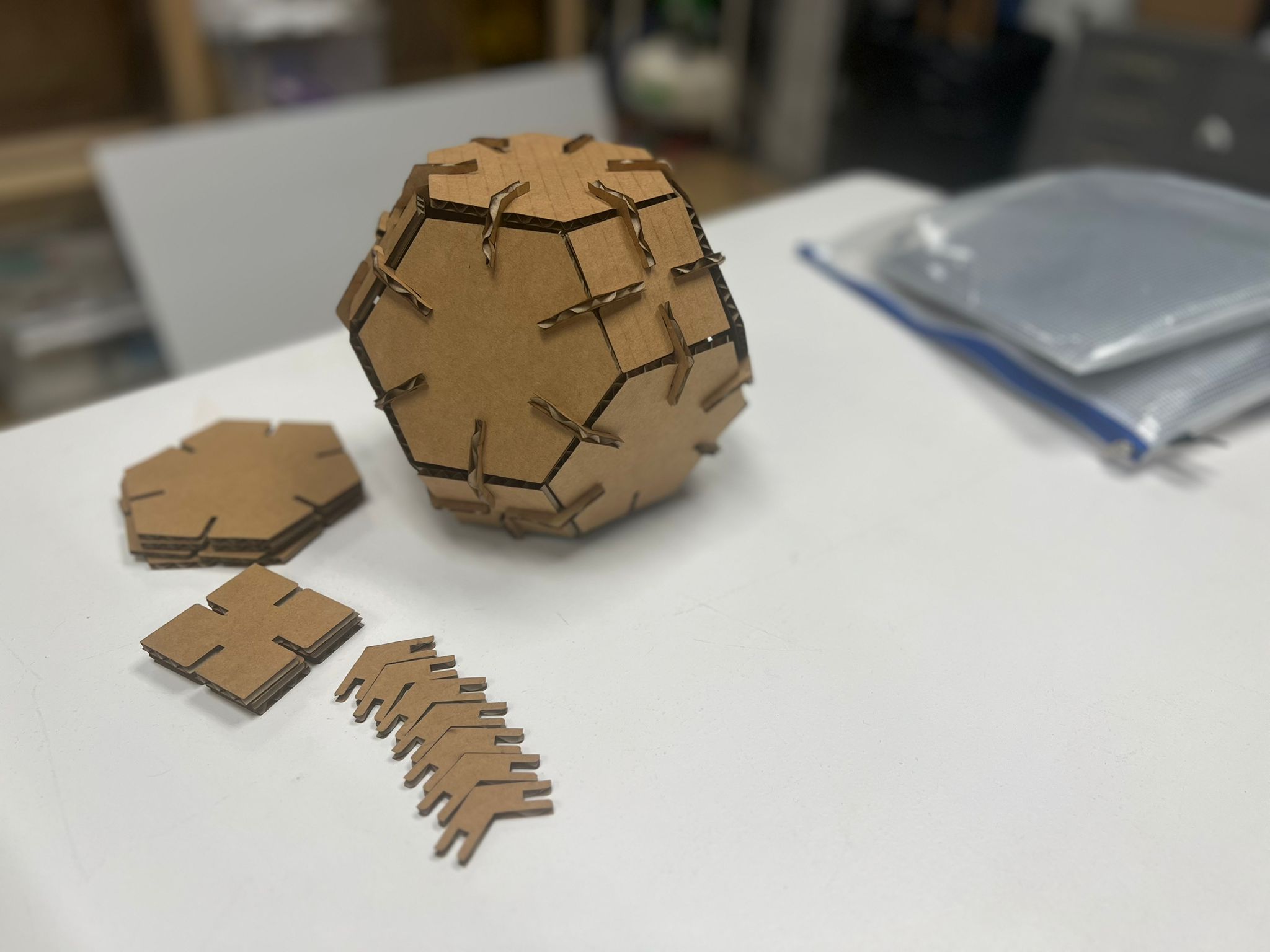
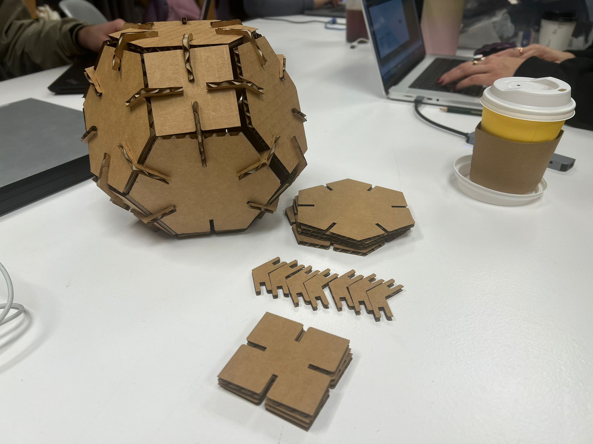
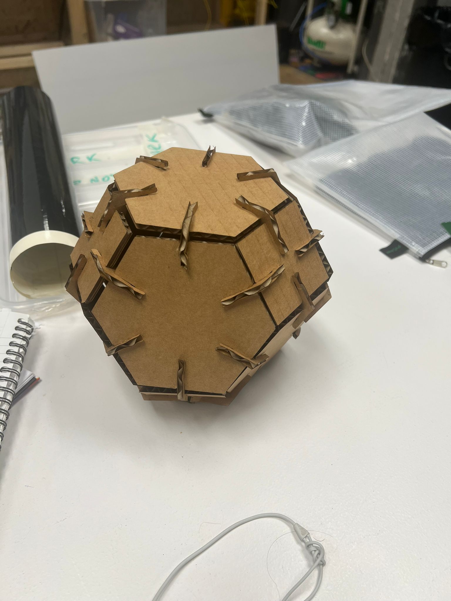
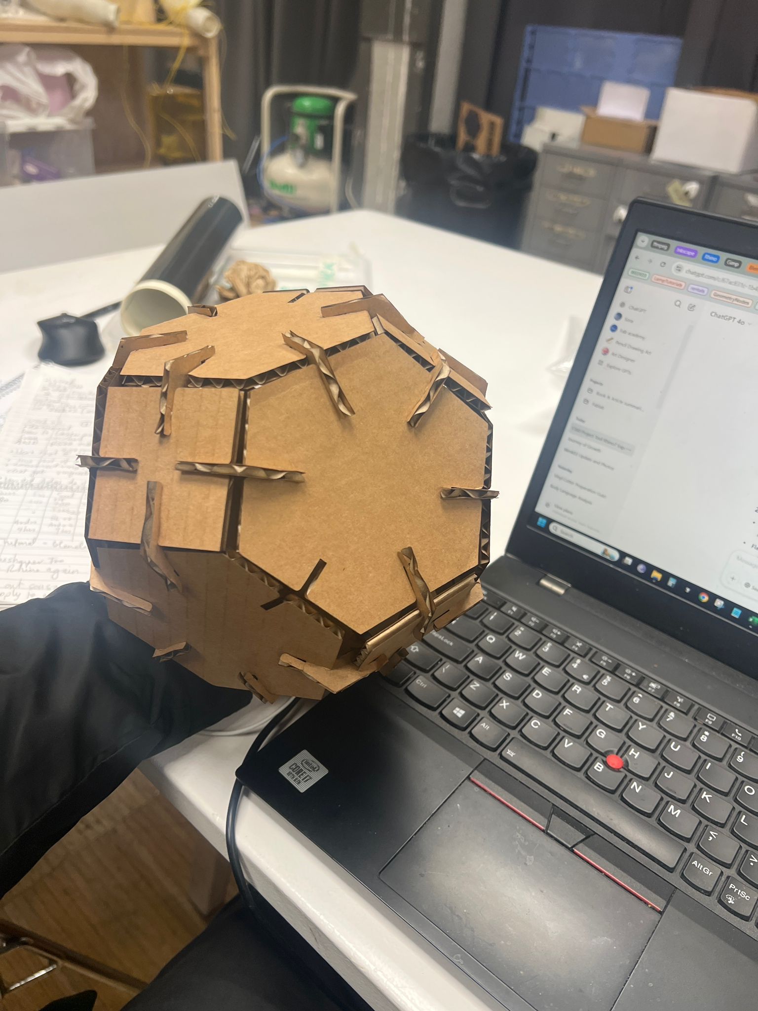
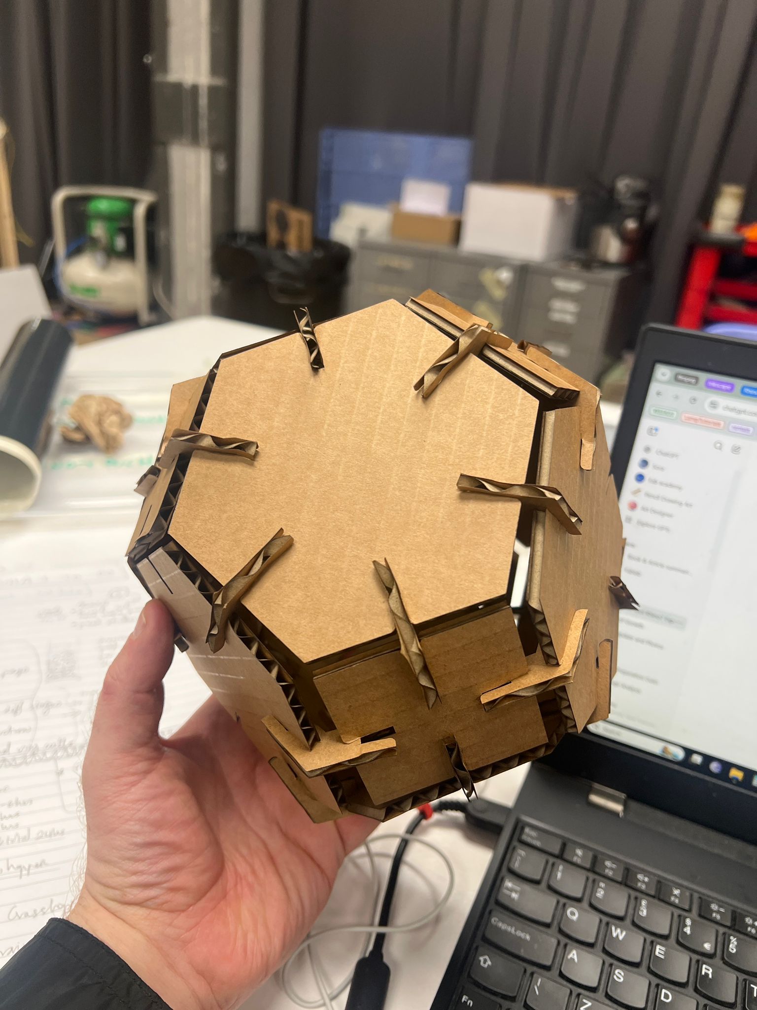
Here are the results of the successful print where the pieces just popped out:
Vinyl Cutting
I had really no idea what I was doing at the start. I wanted to import an image of the Barcelona skyline and then make it into black and white colour and a bubble like texture. Then underneath I wanted to have the words Fab Lab 2025. This was inspired by Rico Kanthatham.
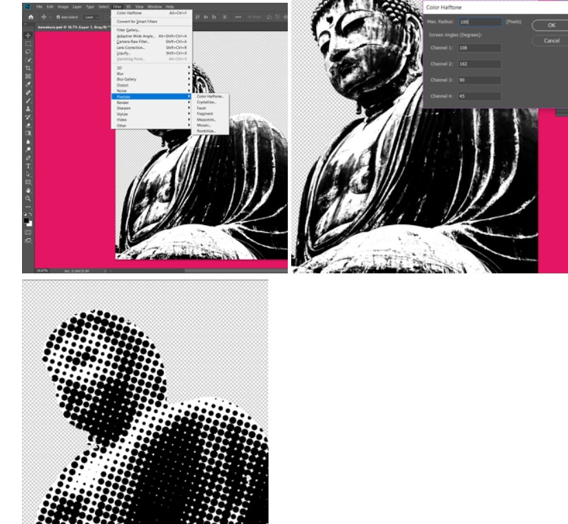
Also, I wanted another design with my initials and year of birth and some other designs. This has been on my mind for the last few days as I couldn't do it last week either. Today I went through three Inkscape tutorials. No success so far.
For example, I created some text and then wanted to make the font into a path so that later I could add some more effects and then focus on preparing it to get cut on vinyl. However, I'm missing something and Inkscape wouldn't fully convert the text to a full path. Poor old chatgpt had many suggestions but none of them worked so far!
I still have some time and am going through some more tutorials – this WILL work! Updates to follow.
I came in Tuesday morning frustrated but determined to make something work. I had struggled for two days watching Inkscape tutorials to try and understand what to do.
I chose an image I like, which is Roy Lichtenstein's 1965 pop art piece, 'Sunrise'.
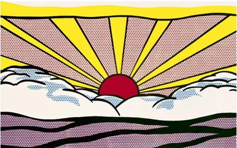
I decided to work on this design and go through everything step by step with Chatgpt. This is what I came up with finally:
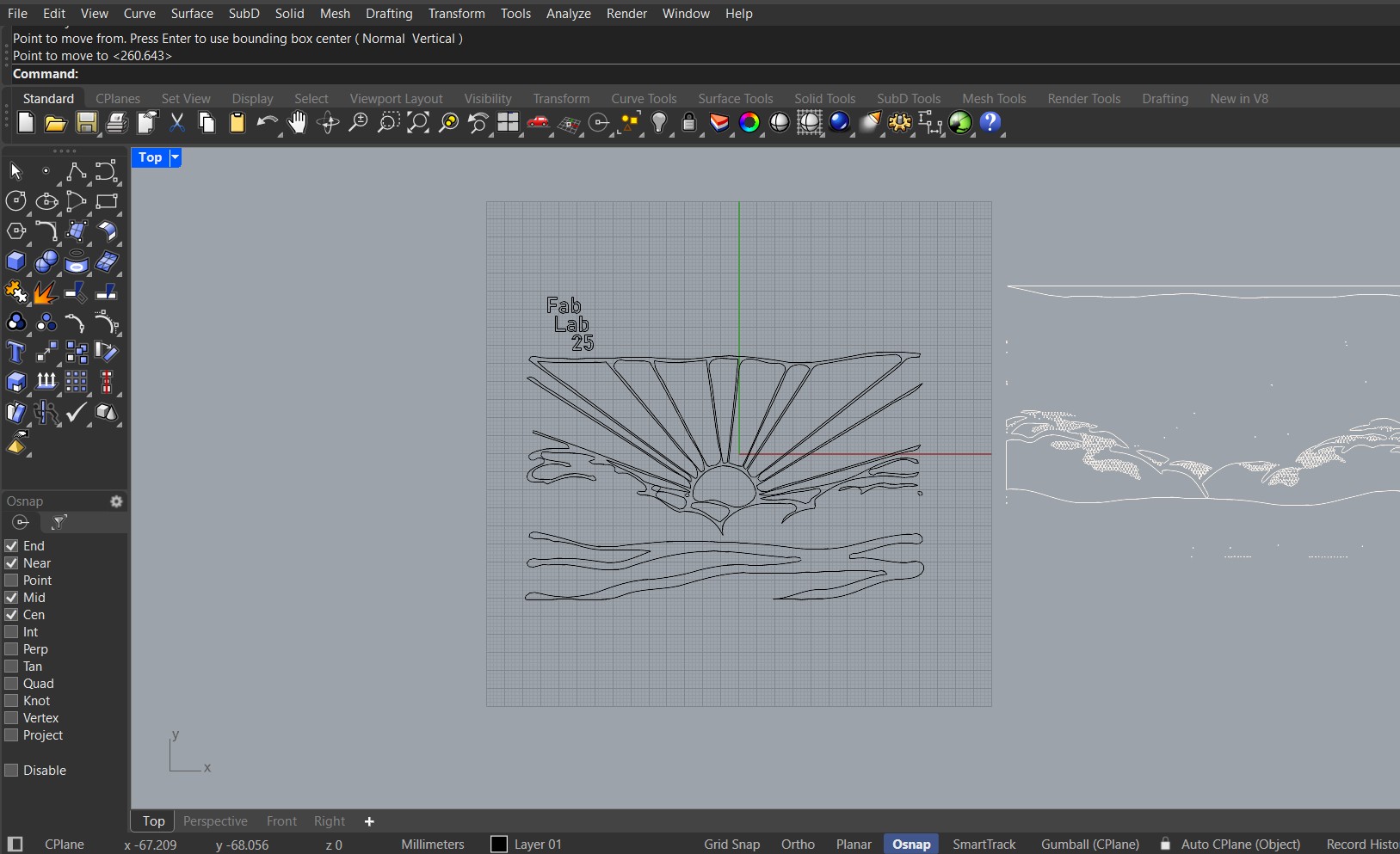
(I have reposted the discussion below in Appendix 1 highlighting my questions and the detailed answers).
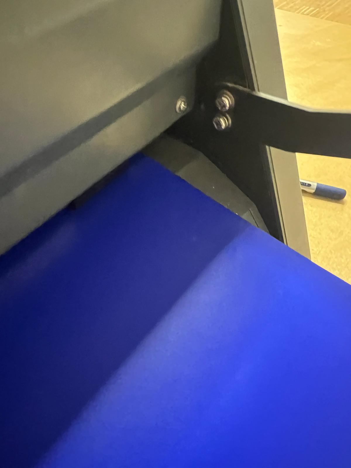
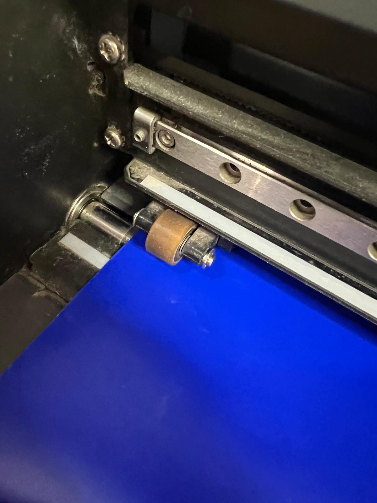
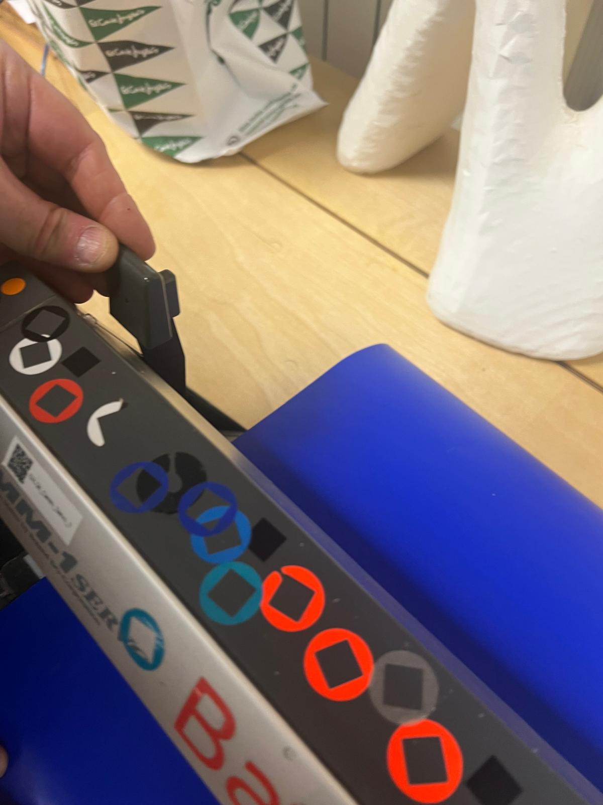
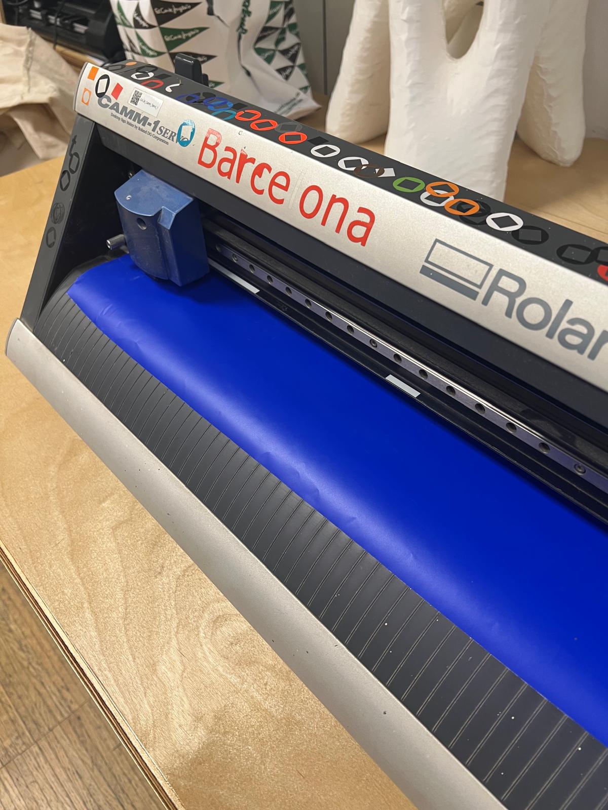
Once I had the file, Adai showed me how to input the vinyl paper into the back of the Roland machine and set the rollers on the paper explaining how they will sense the paper.
We are prompted to input the roll
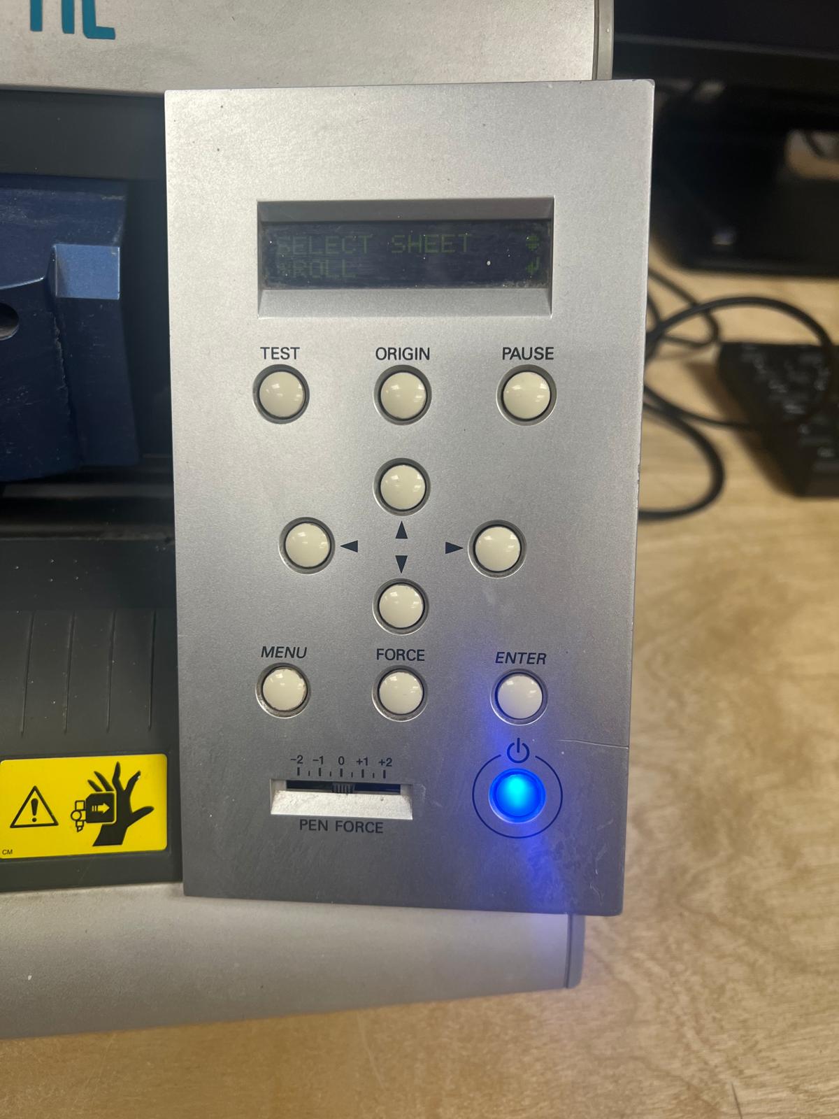
We open the rollers and feed paper in from the back end
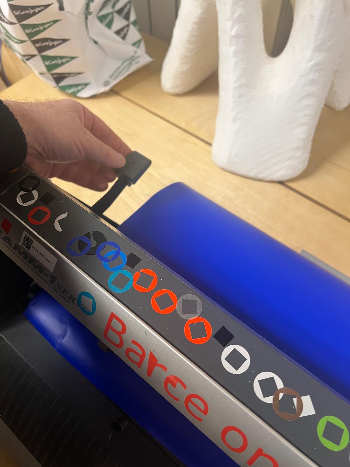
Rollers are adjusted from the back and we feed paper in from the back
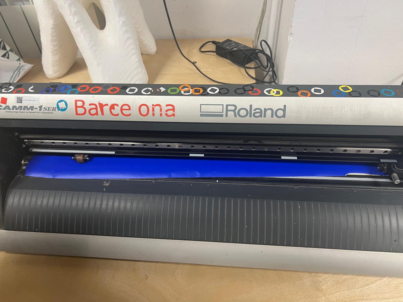
Back View
Front View
Closing Clamp to secure the paper
Ready to check file boundary before printing
Print preview showing that we need to position the file at the start of the roll so as not to waste material
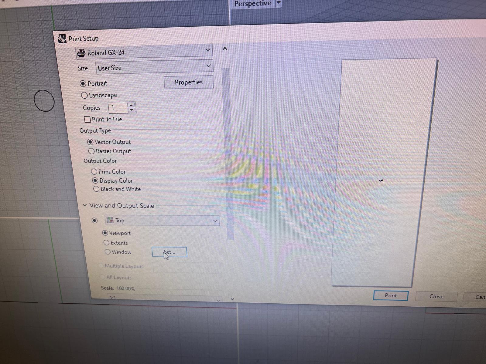
Final Print Preview after design moved close to the origin point so as not to waste paper
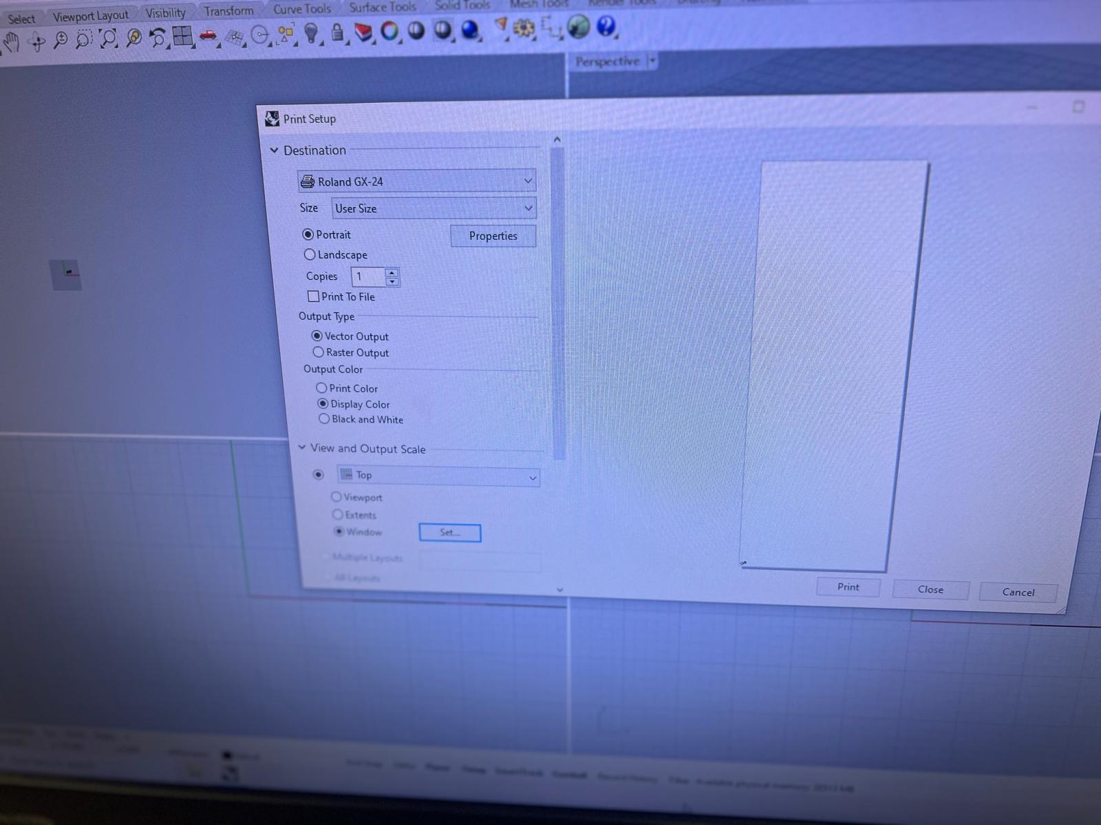
I also had to set the cutting piece to a certain length. It was a random approximation and not precise like the laser cutter. Then we printed a test sticker.
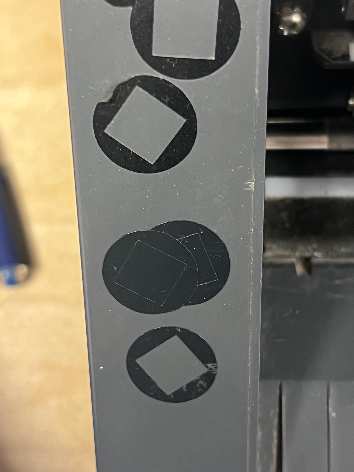
Printing a test square to make sure everything is aligned and working
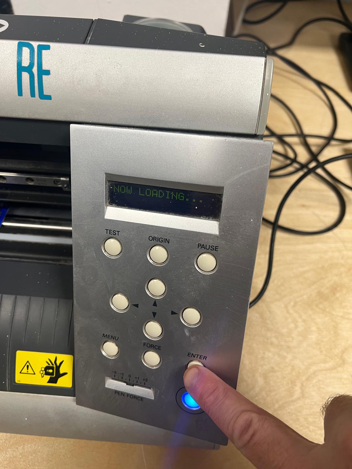
Pressing enter to load the design and print it out
VIDEO COMPRESSION SOFTWARE
Up to now I had trouble compressing video. Thanks to my Global evaluator Krisjanis Rijnieks for pointing out Handbrake which was the first software I tried that worked pretty much first time.
See the results below:
I filmed part of the process of peeling the vinyl sticker. My original file size was just over 5 MB. I used Handbrake video compression software to reduce the size and this shows that the final video was 1.7 MB.

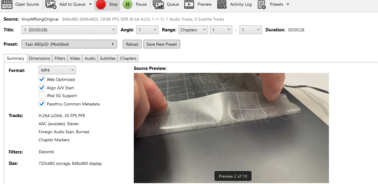
This second image is how the software looks. I selected the video quality from 1080p to 480p, chose the file i wanted to save to and the program closed once it had compressed the video file
APPENDIX 1
Step 1: Import the Image into Inkscape
- Open Inkscape.
- Import the Image:
- Click File > Import.
- Select your image file (image.png).
- Choose Embed when prompted and click OK.
Step 2: Convert the Image to a Vector (Trace Bitmap)
- Since this is a raster image (PNG/JPG), it must to be converted into a vector path.
- Select the image.
- Click Path > Trace Bitmap (Shift + Alt + B).
- In the Trace Bitmap window:
- Choose Multi-Scan Colors (since this image has multiple colors).
- Set Scans to 5-6 (higher scans capture more details).
- Enable "Smooth" and "Remove Background".
- Click Update, then OK.
- Delete the original image (you now have a vector version).
Step 3: Edit the Vector Paths (If Needed)
- Select the Node Tool (F2).
- Click on different parts of the design to see editable nodes.
- Simplify paths if there are too many nodes:
- Click Path > Simplify (Ctrl + L).
- Fix any missing parts by adjusting nodes.
Step 4: Prepare for Cutting (Set Strokes & Remove Fills)
- Open Fill and Stroke (Shift + Ctrl + F).
- Remove Fill:
- Go to the Fill tab and click the X (no fill).
- Add Stroke (Outline for Cutting):
- In the Stroke Paint tab, click Flat Color.
- In the Stroke Style tab, set Width to 0.01 mm.
Step 5: Save in a Cutter-Friendly Format
- Click File > Save As.
- Choose Plain SVG (.svg) for Cricut, Silhouette, or most vinyl cutters.
- If your cutter requires DXF:
- Choose AutoCAD DXF R14.
- Enable ROBO-Master units if available.
Step 6: Test the File in Your Cutter's Software
- Import the SVG/DXF into your cutting software.
- Check if it detects the cut paths correctly.
- Adjust size and positioning if needed.
Now, your pop-art style sunburst image is ready for vinyl cutting! 🚀
Let me know if you need more details or troubleshooting!
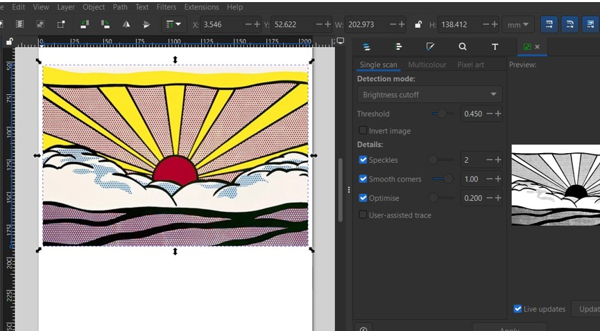
where is multiscan?
You're currently in Single Scan mode in the Trace Bitmap tool. To enable Multi-Scan (which allows tracing multiple colors), follow these steps:
How to Find and Use Multi-Scan in Inkscape
- Make sure the image is selected (click on it).
- Go to Path > Trace Bitmap (Shift + Alt + B).
- At the top of the panel, you'll see three tabs:
- Single Scan (currently selected)
- Multi-Colour (this is what you need)
- Pixel Art
- Click on Multi-Colour.
- Adjust Scans (Number of Colors):
- Set 5-10 scans for simple images.
- Set higher scans (e.g., 15-20) for detailed color separation.
- Click Update to preview.
- Click Apply to generate the vector.
Next Steps After Tracing
- Ungroup (Shift + Ctrl + G) to separate the traced layers.
- Delete the original image (you only need the vector paths).
- Simplify the design if needed with Path > Simplify (Ctrl + L).
- Set stroke to 0.01mm (for cutting) and remove fill.
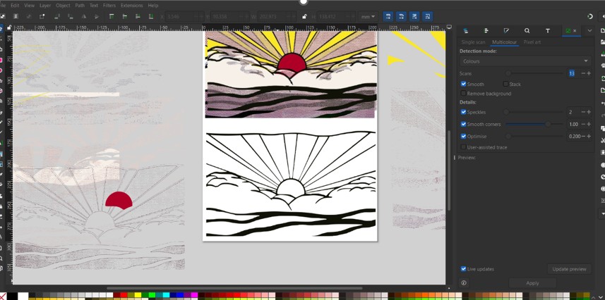
look at centre bottom - that looks like the traced image to me - do you agree? Whats next?
Yes! The center bottom image looks like the traced version—it has clean black outlines and is separated from the original, meaning the vectorization process worked. 🚀
Next Steps: Prepare the Traced Image for Cutting
Now that the image is traced, follow these final steps to make it cuttable:
1. Ungroup and Delete Unwanted Parts
- Select the traced image (click on it).
- Press Shift + Ctrl + G (Object > Ungroup) multiple times until no groups remain.
- Delete any unnecessary elements (e.g., unwanted color layers, background duplicates).
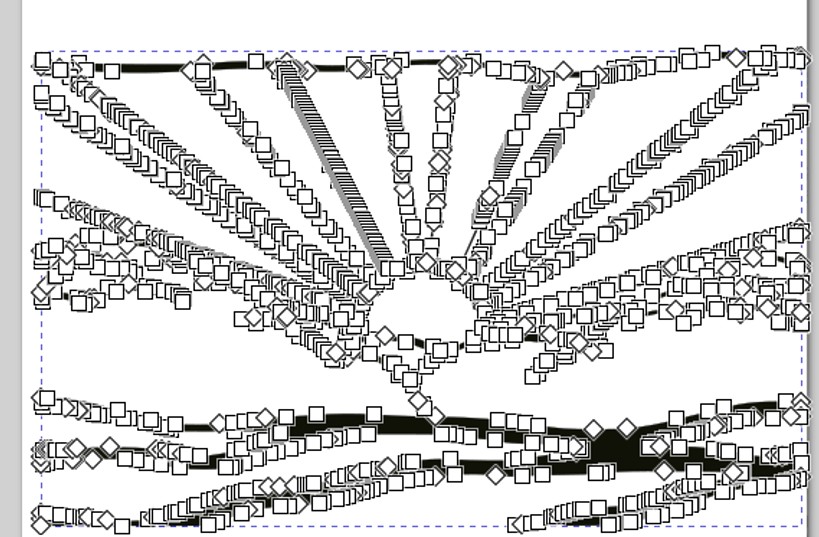
in your step 1 i see this and when i hovered over top part the sunshine rays they appeared blue for a second
Great! If the entire traced image turned blue for a second when you hovered over it, that means the vector paths exist and are selectable, but they are likely too complex or too thin to see properly.
Step-by-Step Fix: Convert to Proper Stroke Paths
- Select the traced image.
- Open Edit Paths by Nodes (F2).
- If you see thousands of tiny nodes, the image is too detailed for clean cutting.
- Click Path > Simplify (Ctrl + L) to reduce nodes while keeping the shape.
- Add a stroke before removing fill:
- In Stroke Paint, select Flat Color (black or red).
- In Stroke Style, set Stroke Width to 0.5mm for now.
- Later, reduce it to 0.01mm for the vinyl cutter.
Now your file should be ready for cutting! 🚀