Week 07: Computer Controlled Machining
Assignment
Group Assignment
- Complete your lab's safety training
- Test runout, alignment, fixturing, speeds, feeds, materials and toolpaths for your machine
- Document your work to the group work page and reflect on your individual page what you learned
Individual Assignment
- Make (design+mill+assemble) something big
Learning Outcomes
- Demonstrate 2D design development for CNC milling production
- Describe workflows for CNC milling production
A Brief Introduction
Introduction to CNC Milling – Key Considerations
CNC (Computer Numerical Control) machining is a subtractive manufacturing technology. Parts are created by removing material from a solid block (called the blank or the workpiece) using a variety of cutting tools.
CNC Anatomy
(Source: FabLab BCN Documentation: https://fablabbcn-projects.gitlab.io/learning/educational-docs/fabacademy/classes/07-Computer-controlledMachining/ )
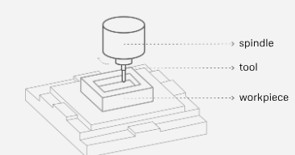
In this above image we see the components in the CNC Milling Setup. The Spindle is the rotating part of the machine that holds the tool. The Tool is the cutting part that removes material from the workpiece. (This specific image shows pocket milling, where the tool removes material from an internal cavity).
(Source: FabLab BCN Documentation: https://fablabbcn-projects.gitlab.io/learning/educational-docs/fabacademy/classes/07-Computer-controlledMachining/ )
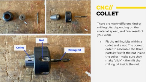
This second image (Collet System) shows how the collet secures milling bits. The Collet is a sleeve that tightly grips the milling bit. Then the Nut holds and compresses the collet. Finally, the Milling Bit is the cutting tool. (N.b. Important! There should be a "click" sound/feel when securing the collet into the nut before inserting the milling bit).
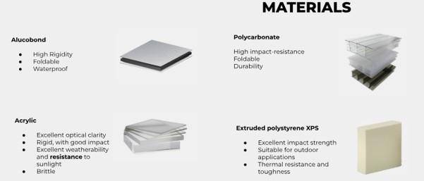
Materials that can be used in CNC Milling and their merits and demerits
(Source: FabLab BCN Documentation: https://fablabbcn-projects.gitlab.io/learning/educational-docs/fabacademy/classes/07-Computer-controlledMachining/ )
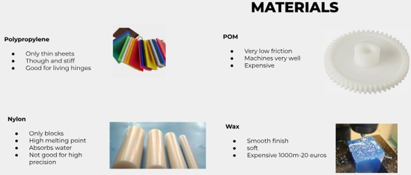
(Source: FabLab BCN Documentation: https://fablabbcn-projects.gitlab.io/learning/educational-docs/fabacademy/classes/07-Computer-controlledMachining/ )
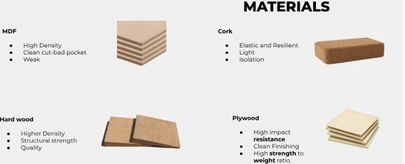
(Source: FabLab BCN Documentation: https://fablabbcn-projects.gitlab.io/learning/educational-docs/fabacademy/classes/07-Computer-controlledMachining/ )
Effect of different kinds of cuts on various materials
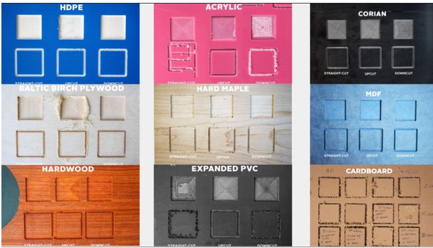
(Source: FabLab BCN Documentation: https://fablabbcn-projects.gitlab.io/learning/educational-docs/fabacademy/classes/07-Computer-controlledMachining/ )
The Assignment – Make Something Big (Out of Plywood)!
It is said that if Steel is the King of Materials then Plywood is the Queen, a delicious wood sandwich. Plywood is more flexible and generally stronger than lumber of the same species and dimensions. Though plywood is very weak along the grain it is very strong across the grain. Plywood's strength and flexibility is in her cross grain constitution. 'AC' is the quality of the exterior plies with A being the highest quality.
The process
- Check and measure the Plywood stock: 2500mm X 1250mm
- Design something BIG: Chair, Standing desk, Coffee table & stools
CAM -> Gcode generation
For the CAM (Computer-Aided Manufacturing) process, I used RhinoCAM, a plugin for Rhinoceros 3D. RhinoCAM allows the creation of toolpaths based on the 3D design and exports them as G-code for CNC milling. Before generating the G-code, I ensured that the diagrams were nested efficiently — meaning the parts were arranged to minimize material waste on the plywood sheet. Nesting can be done in Rhinoceros 3D using NonManifoldMerge all a paid plugin Rhinocam_NEST, or in Fusion 360 with the free 'Arrange' feature or a plugin that costs $1600 per year. I used the free 'Arrange' feature in Fusion 360.
- Gcode is checked by someone
- Design milled
- Design assembled
Introduction to Raptor X SL 3200 CNC Machine in our workshop
I found the following YouTube video showing an instructor in Barcelona demonstrating one of the machines we operate in our milling lab:
Operating the Raptor
Safety Precautions
Prepare safety gear such as:
- Ear Protection
- Safety Glasses
- Avoid loose clothing and tie back long hair
- It's recommended to wear work gloves when handling raw materials but not while operating the machine
Locate all emergency stop buttons on the machine before starting and make sure you are close to it throughout operation. Keep hands away from moving parts at all times. Only one operator should control the machine at a time.
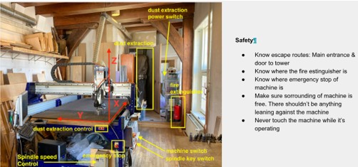
(Source: FabLab BCN Documentation: https://fablabbcn-projects.gitlab.io/learning/educational-docs/fabacademy/classes/07-Computer-controlledMachining/ )
The Yellow and Red coloured Emergency link in the photo below can be pushed in the event of an emergency.
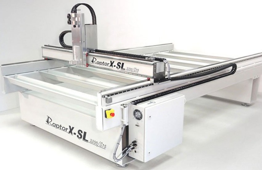
(Source: FabLab BCN Documentation: https://fablabbcn-projects.gitlab.io/learning/educational-docs/fabacademy/classes/07-Computer-controlledMachining/ )
Securing the material using screws:
- Use at least four screws, one in each corner
- Ensure screws are flush with the material to avoid tool collisions
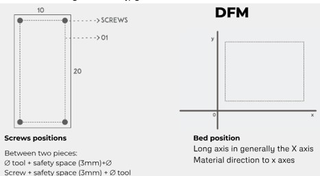
(Source: FabLab BCN Documentation: https://fablabbcn-projects.gitlab.io/learning/educational-docs/fabacademy/classes/07-Computer-controlledMachining/ )
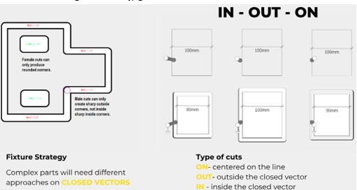
(Source: FabLab BCN Documentation: https://fablabbcn-projects.gitlab.io/learning/educational-docs/fabacademy/classes/07-Computer-controlledMachining/ )
Loading the End Mill
Required Tools:
- End Mill (cutting tool)
- Collet (holds the end mill)
- Collet Chuck (holds the collet in place)
- Spindle-Specific Wrenches (for tightening)
Steps:
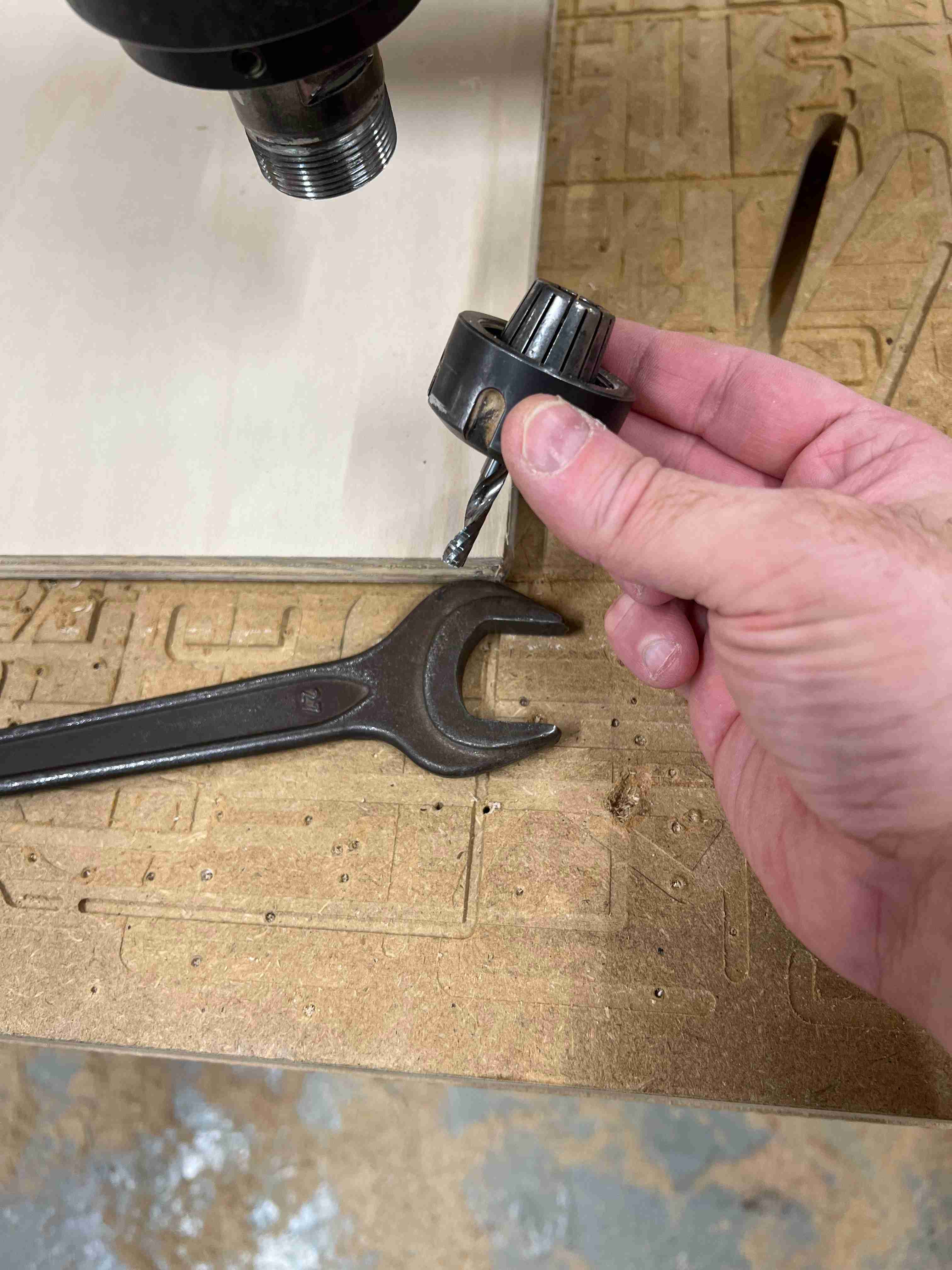
- Insert the collet into the collet chuck until it clicks
- Thread the collet chuck loosely into the spindle
- Insert the end mill into the collet while holding it steady
- Hand-tighten the collet chuck, then use the spindle wrenches to fully secure it
To tighten: Turn the outer wrench clockwise while holding the inner wrench steady.
To loosen: Turn the outer wrench counterclockwise.
Setting X, Y, and Z Origins
X and Y Origin Setup
- Use the remote control joystick for fine adjustments
- Move the end mill to the desired X, Y starting point
- Check alignment:
- Look parallel to the X-axis and parallel to the Y-axis to verify accuracy
- Once aligned, confirm the X and Y origins in the software
Z Origin Setup (Using the Z-Probe)
- Locate the Z probe (a small metal button attached magnetically near the machine computer)
- Place the Z probe directly under the end mill, ensuring it is centered
- In the control software, go to Custom > Zero Finder with Length Probe
- Click to start the process – the machine will:
- Lower the end mill until it gently touches the probe
- Automatically stop and move back up
- Once completed, remove and store the Z probe
Individual Project
So we had to produce something big, meaning something metre size and it is going to milled in plywood. We have been given a sheet of 2500x1250mm plywood for this task.
I really wanted to create a standing desk or a chair for this project as we are sitting for many hours of the day in class and I thought it would be something good for myself and for the FabLab.
At this point my Fusion is still not good and I am having substantial trouble realising my design. Also, Dani mentioned that as is, this will be too unstable currently. I decided to come back to it later when my Fusion 360 improves and for now I have decided to make a small knee height table which is perfect to put something on. I have honestly been having so much trouble even with this (what I thought should be) simple table. I realised I need a pocket cut if I want to have a table top without anyone seeing joint, and I need to somehow join the legs to the struts supporting it. Adai and Dani suggested that I might need a little lesson to boost my Fusion 360, and so they arranged for Didac Torrent to give me some of his time, which was very kind of all of them.
Didac showed me some new commands like JOINT, and the table was built.
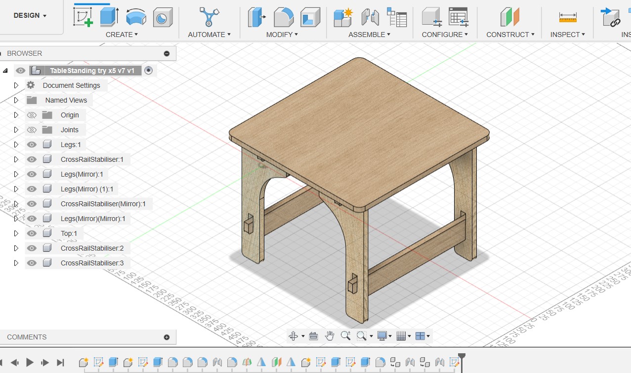
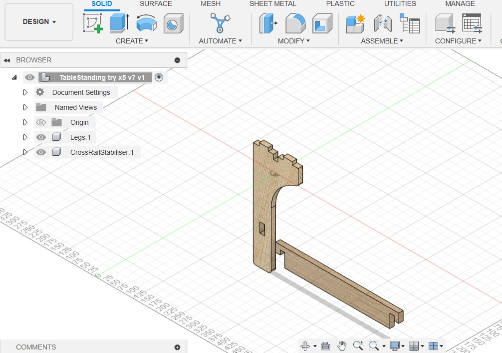
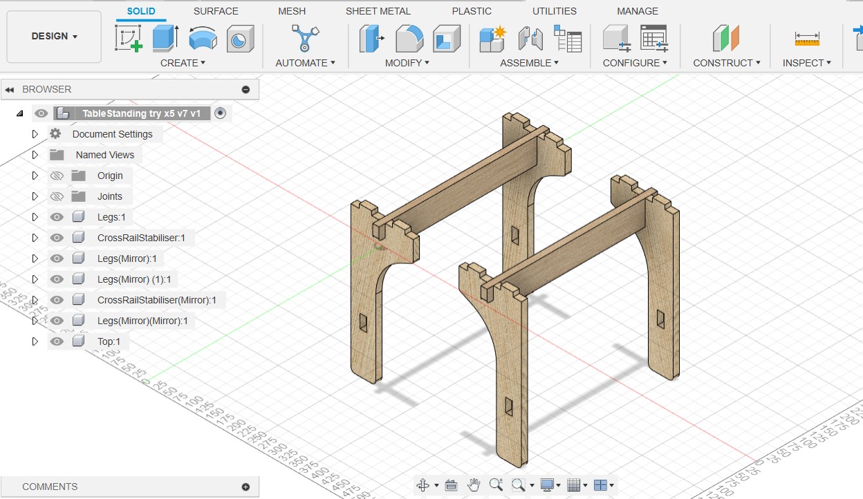
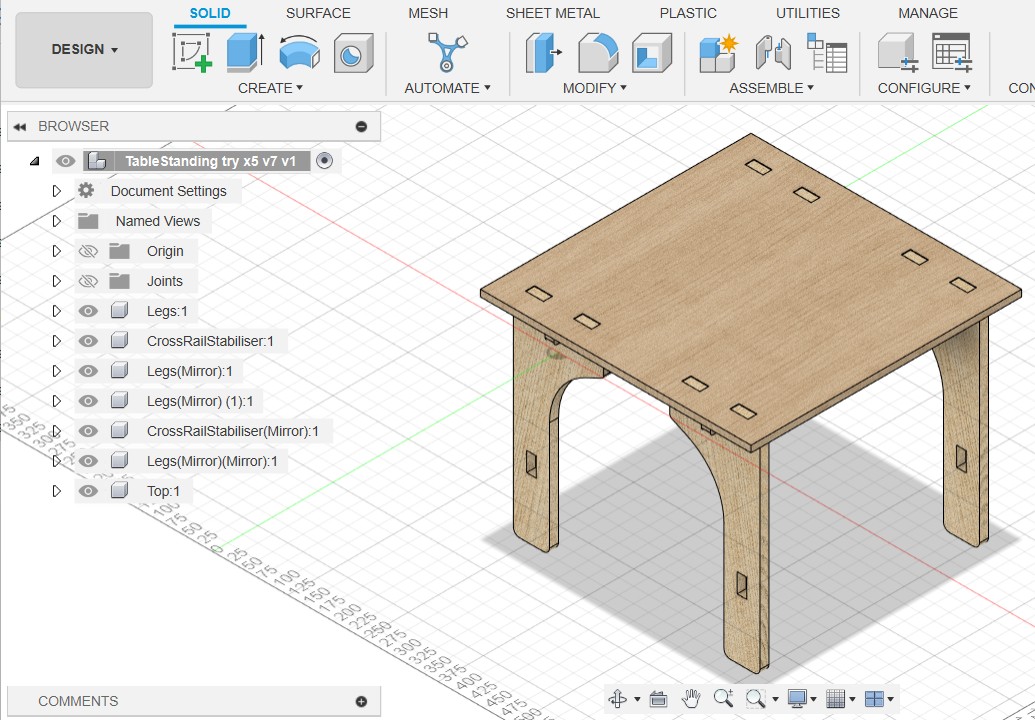
Well, it's not all I had dreamed but it's my first table! So, from here I imported the file into RhinoCam and Dani helped me to slice it so we could prepare the layers and get the G code and toolpath.

This was very overwhelming for me the first time. I want to learn more (Fusion360 plus RhinoCam) so I can complete my standing desk.
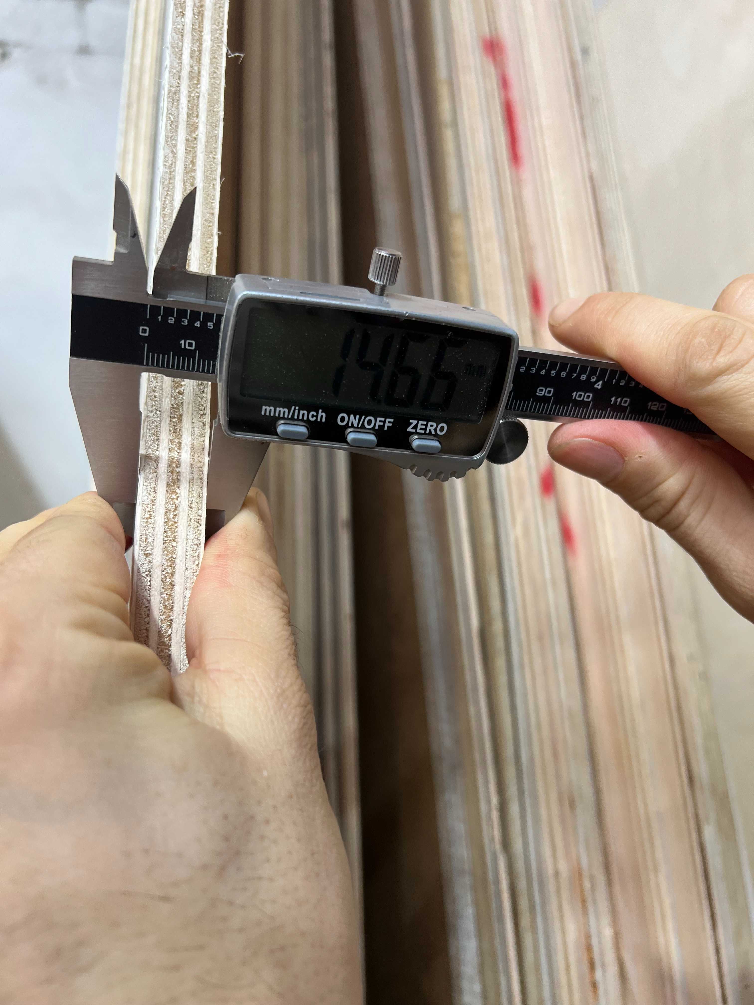
Plywood Stock Measurement
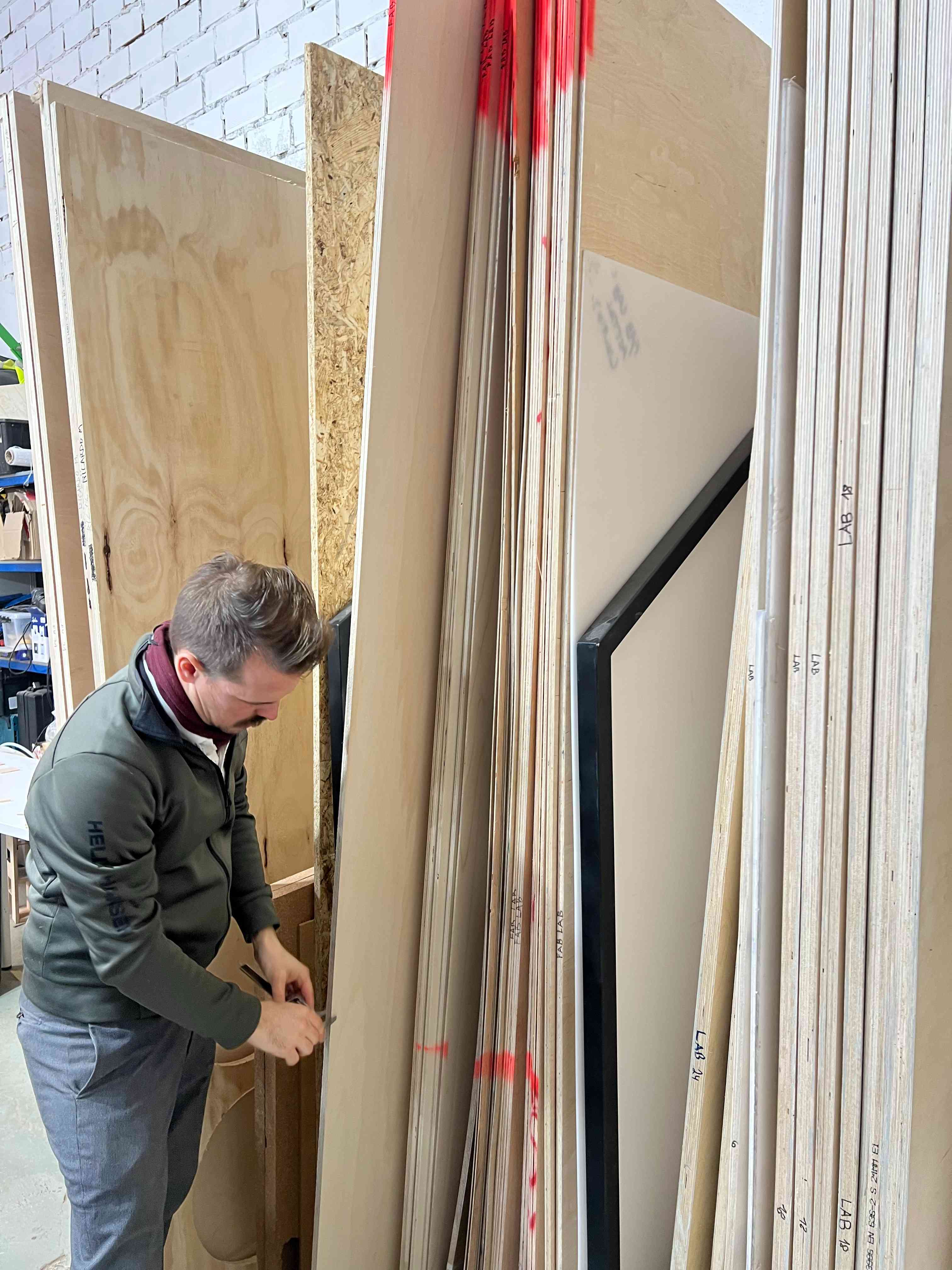
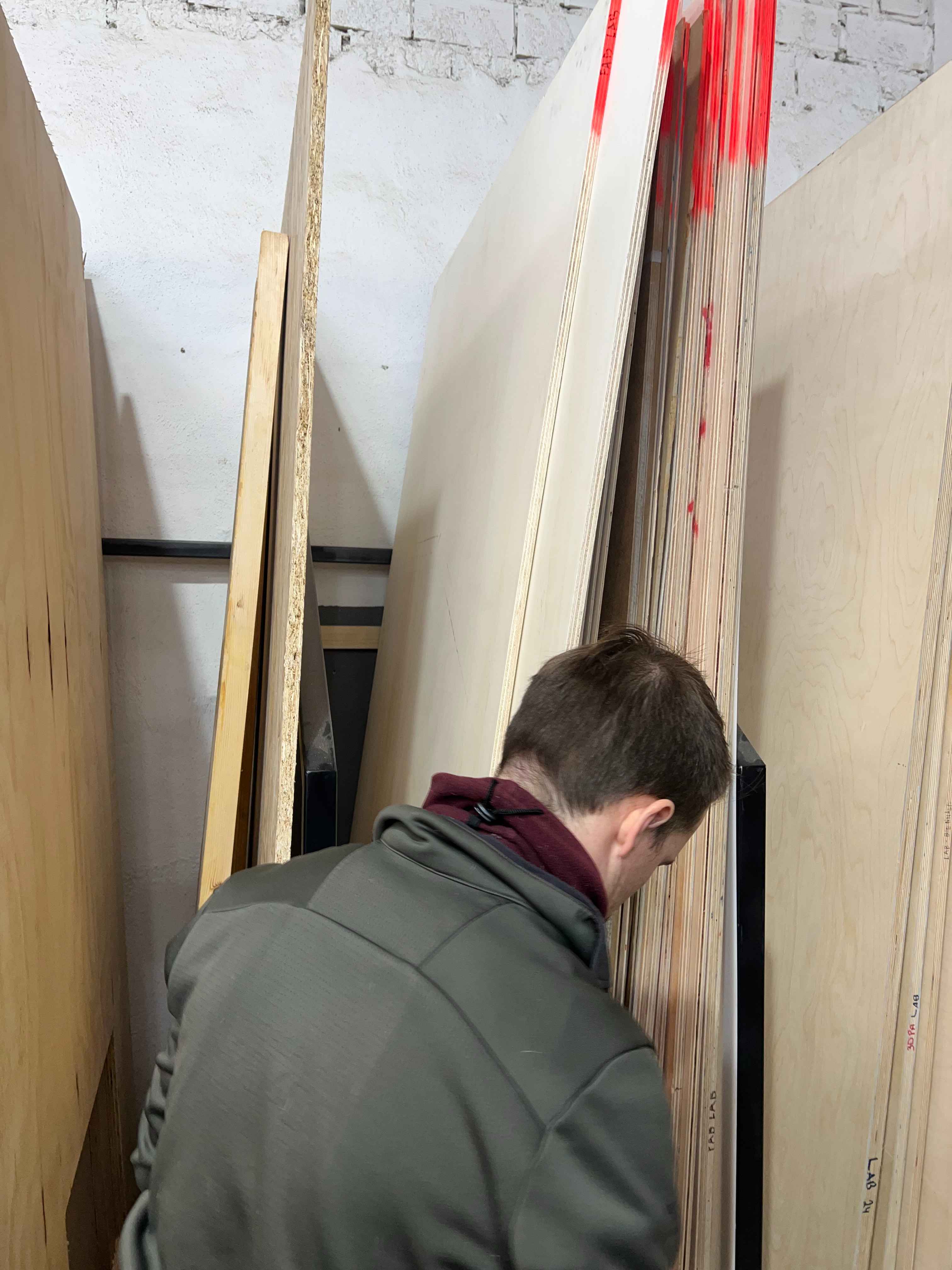
After designing and slicing my file I went with Dani to measure some plywood stock. We measured and it seems to be 14.5mm and 14.75mm, and we reflected that in the sliced file by using a value of 15.5mm for our stock.
Machine Setup
Next we looked for a drill to drill in the screws on the material and secure it on the CNC mill bed so nothing flies away and the right end mill
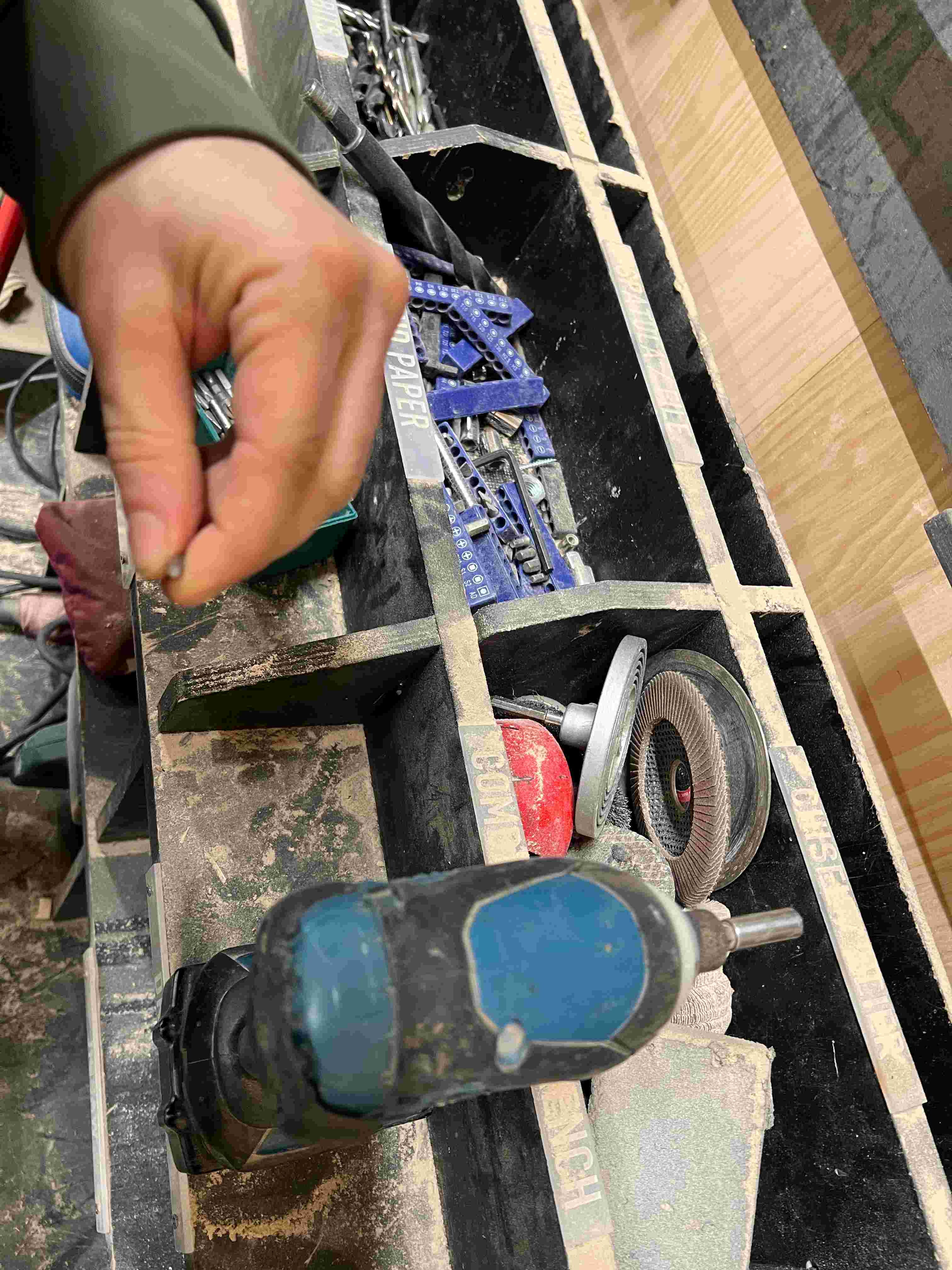
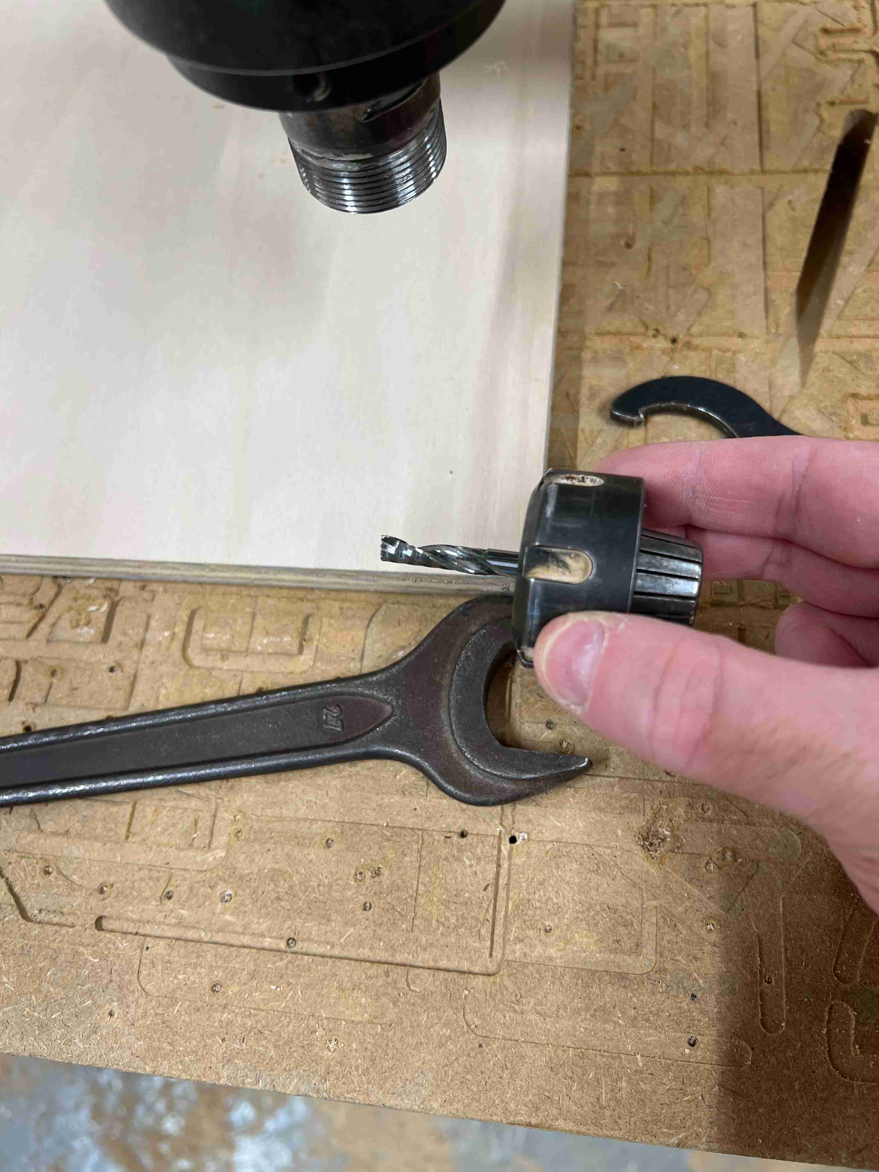
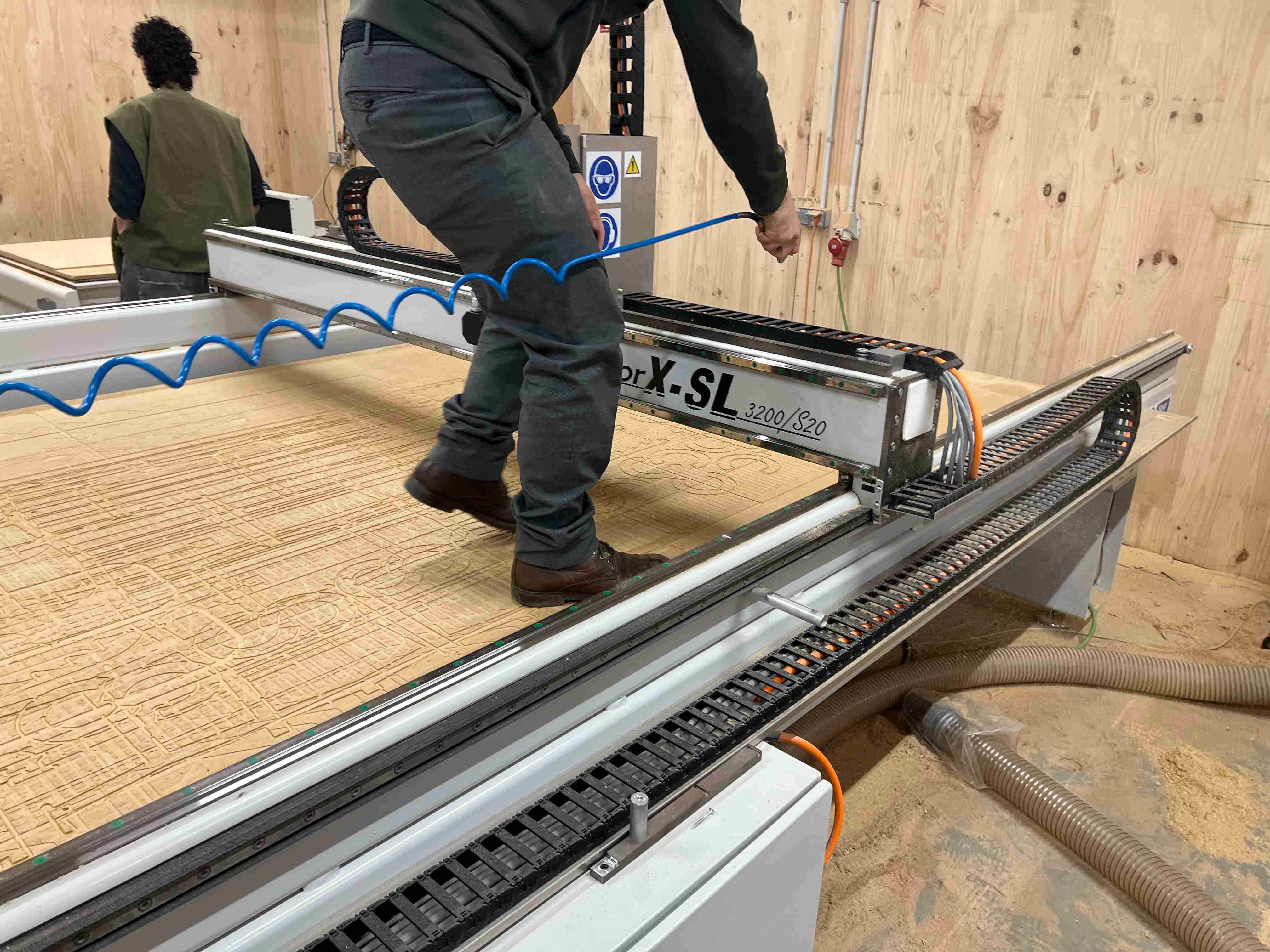
First I cleaned the machine's surface by air spray the bed.
Then we setup the milling software so we can engrave the wood and screw the material down in place for safety.
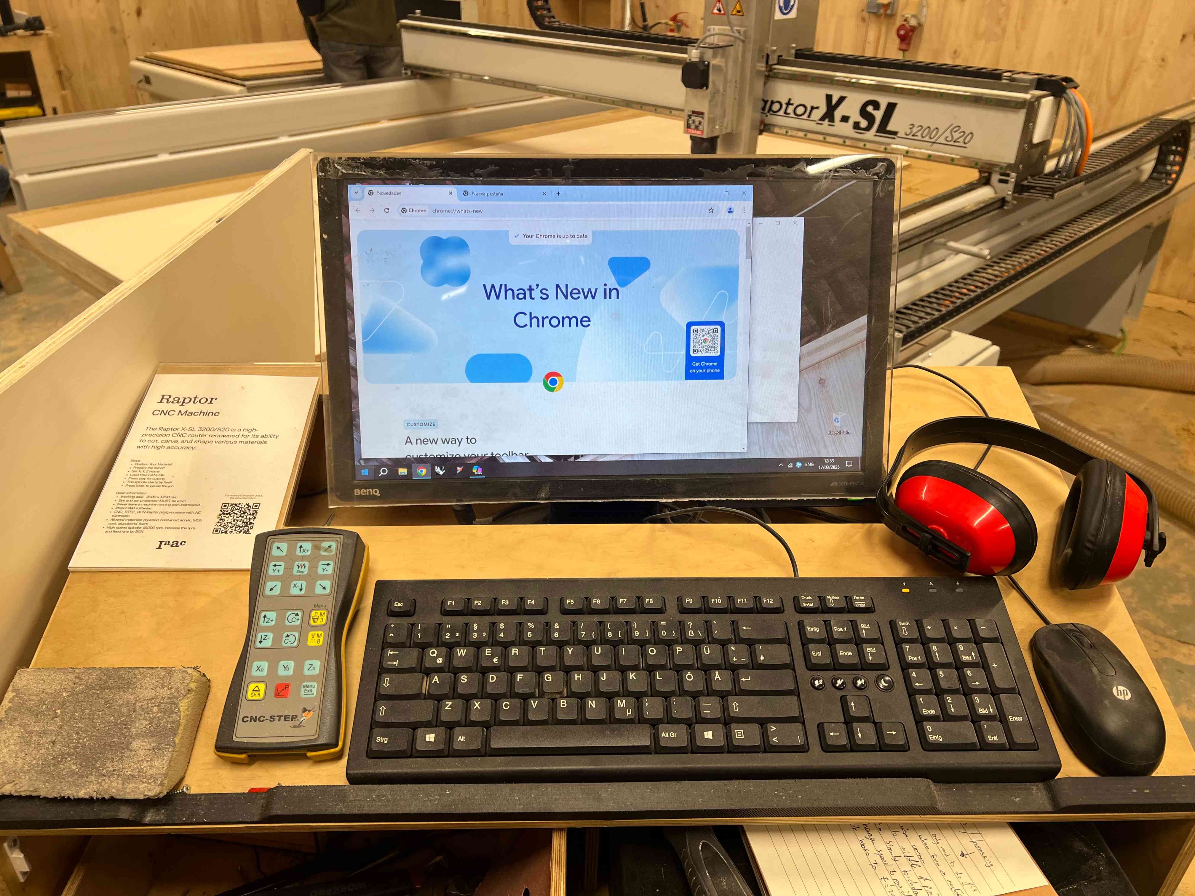

This is how the control area looks and the first job is to orient oneself with the controls, make sure the engraving and cutting files are uploaded to the IAAC cloud.
We then start up the Kinetic software
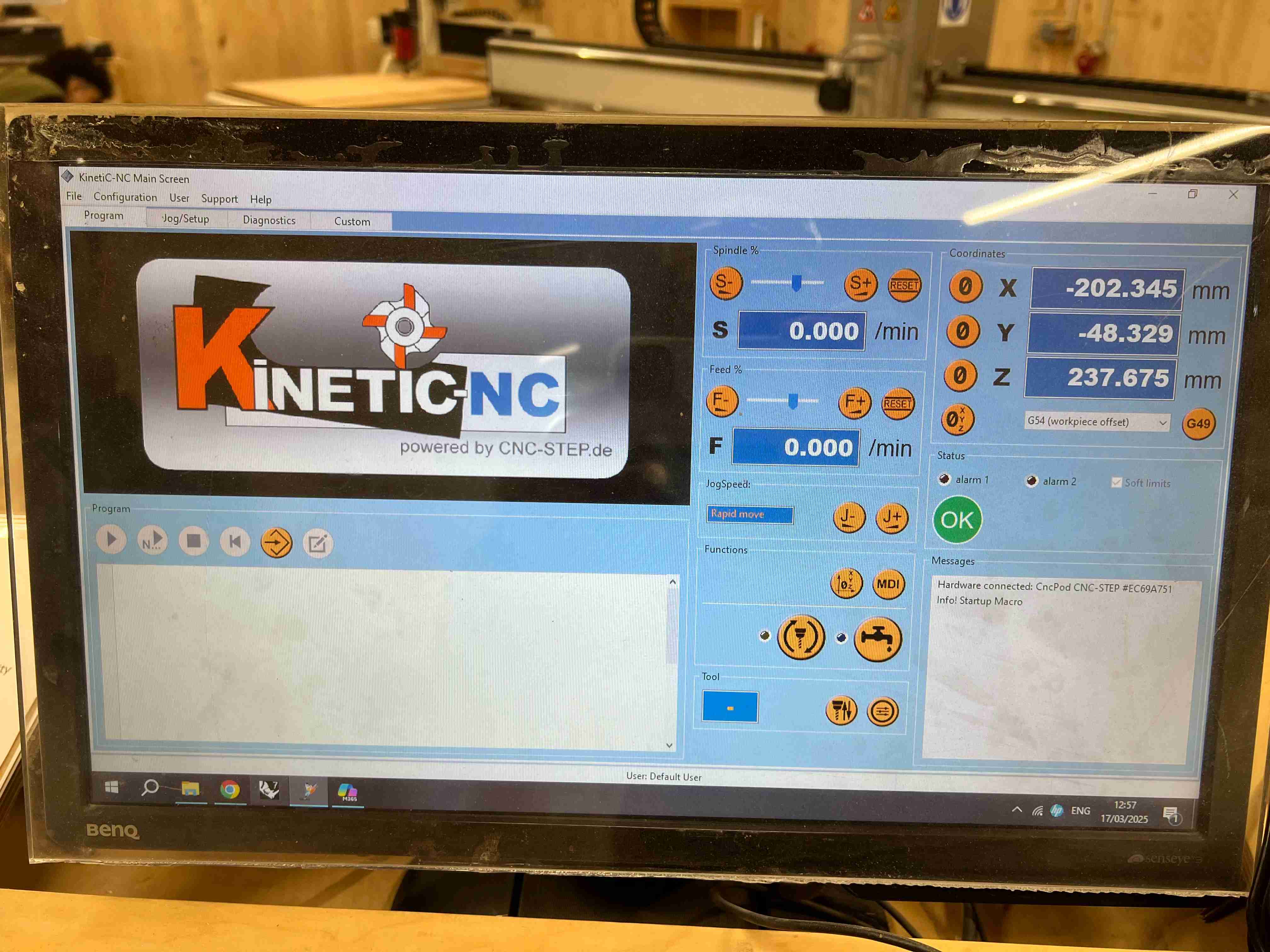
And I upload the file and bring the machine to a zero position which is the point of the bottom right edge of the wood.
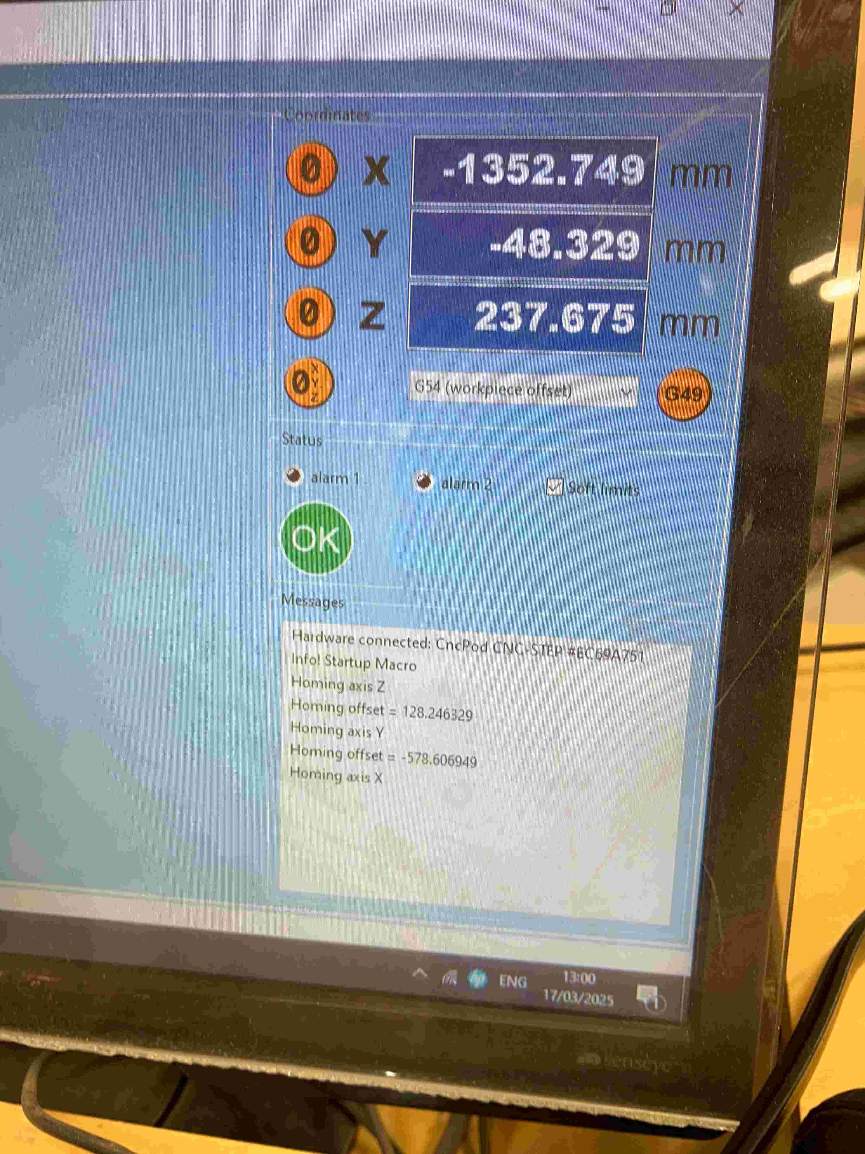
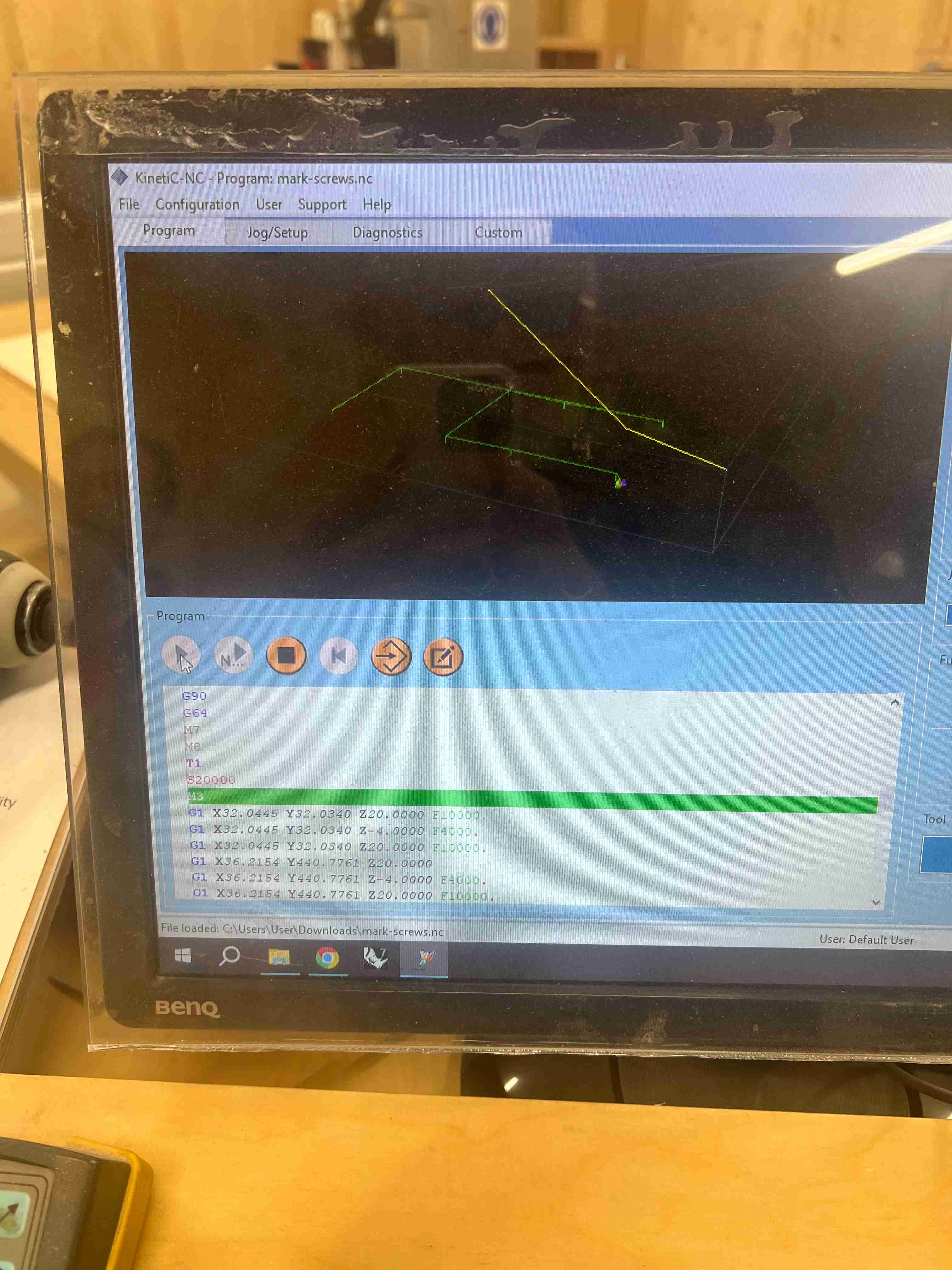
So now we can see that the toolpath is highlighted in Kinetic, if we move the bed far away from its current zero point, kinetic updates the toolpath in real-time.
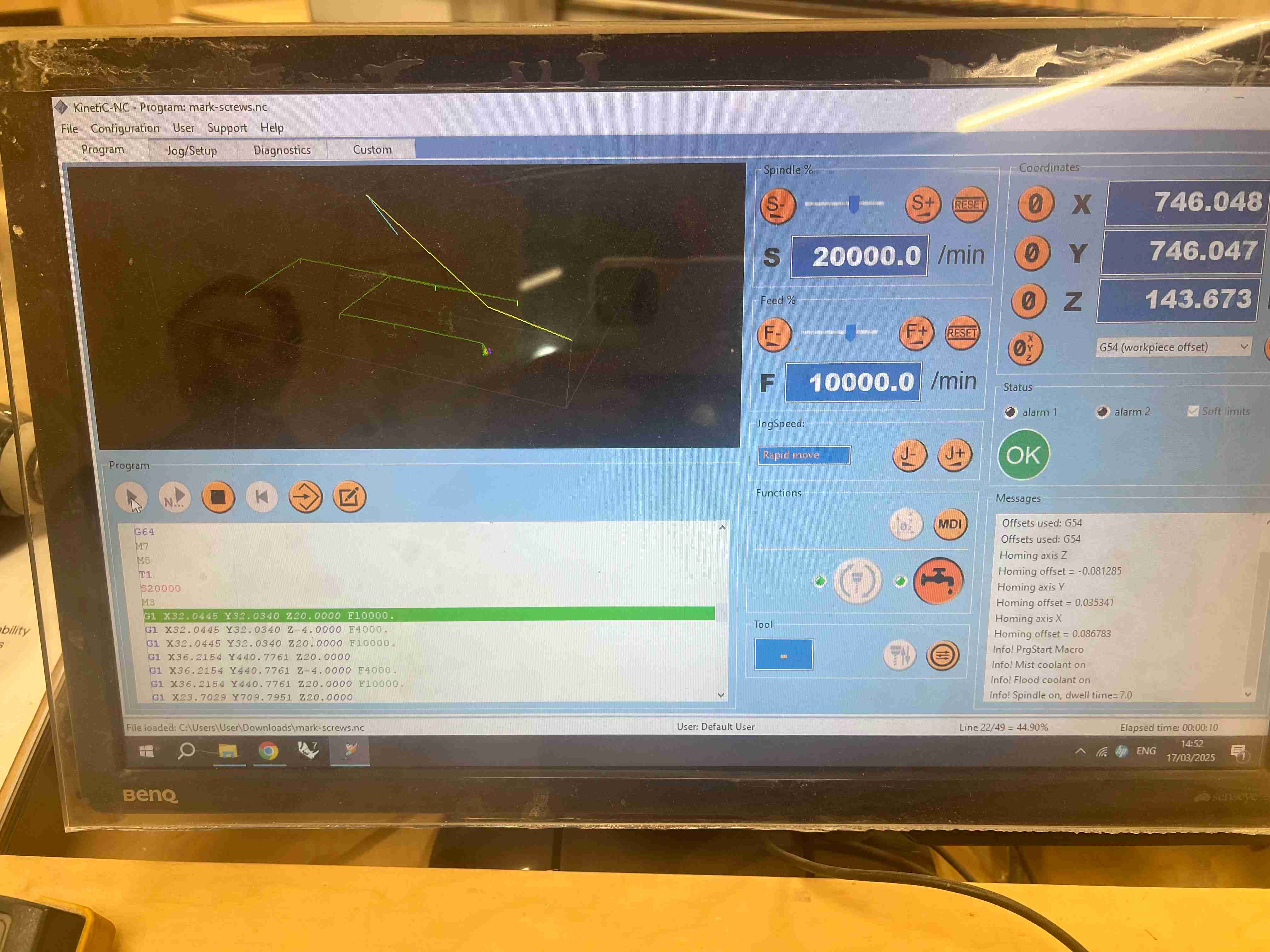
We click Play and the machine starts engraving where the screws are going to go.
After the engraving is done I get to screwing in the material
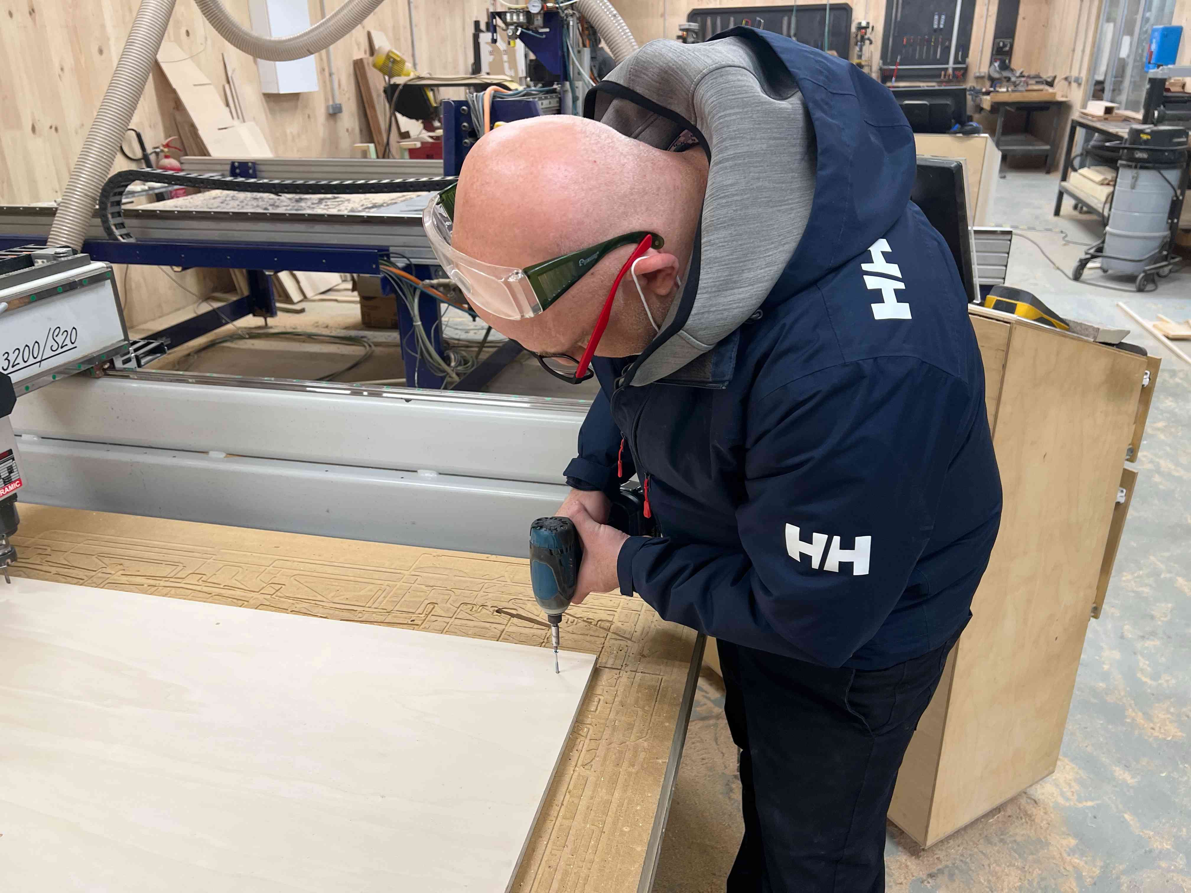
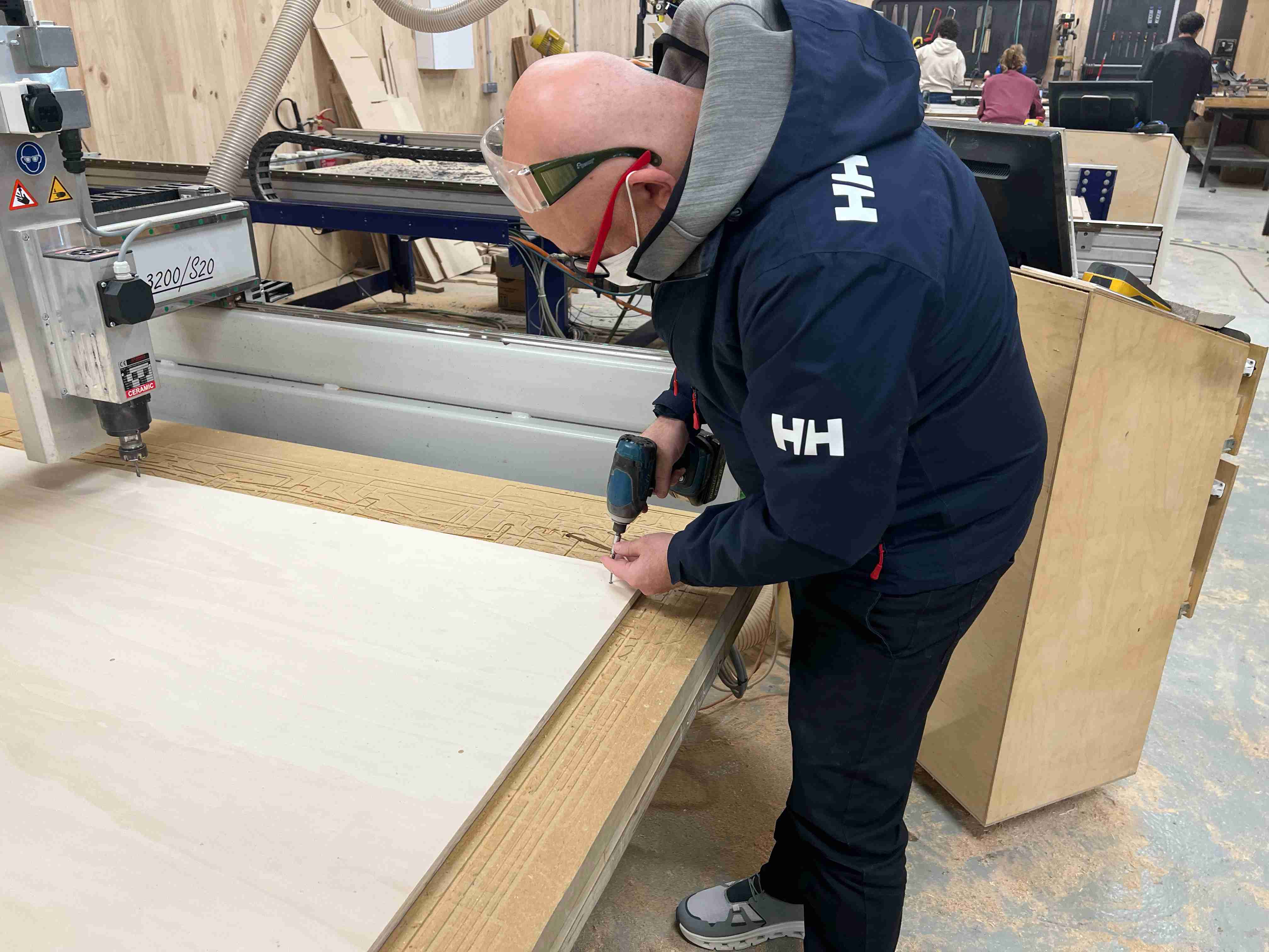
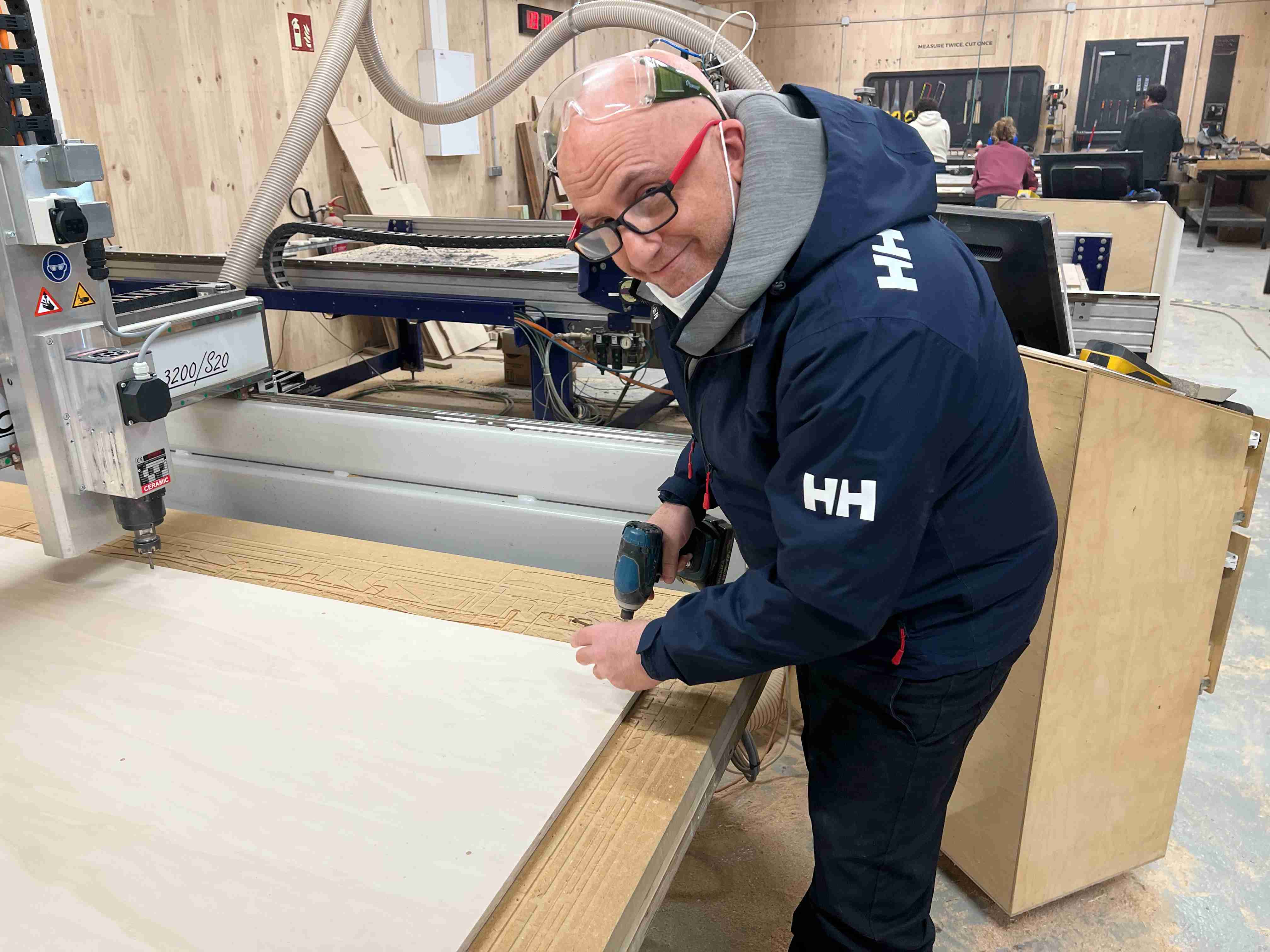
There was one little issue where the screws were too close to the edge of the material and I had to screw it in from an angle – good to be aware of the margin in Rhino cam which I made (20mm) but also careful in the positioning of the screw. This was totally ok but just worth mentioning.
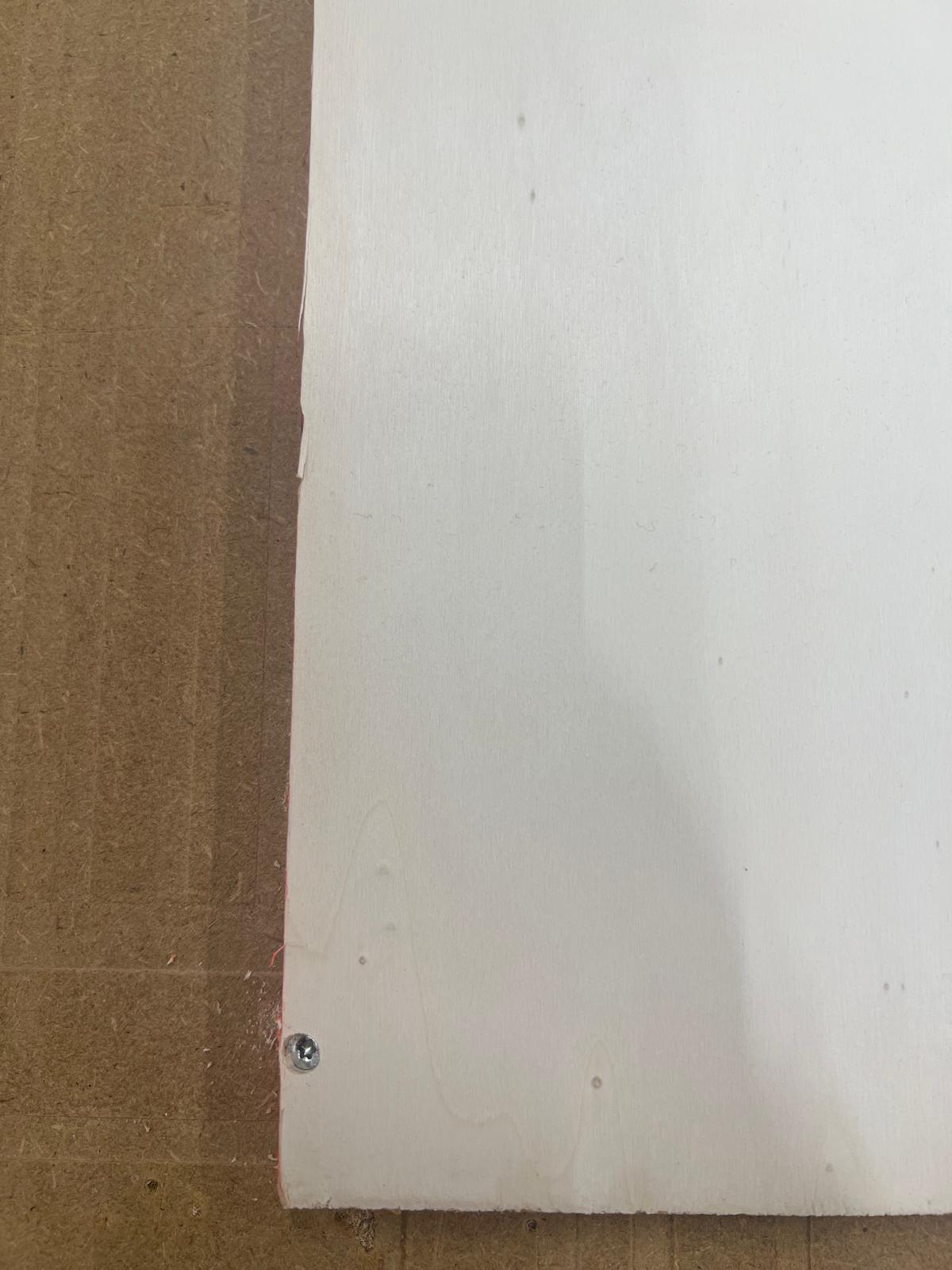
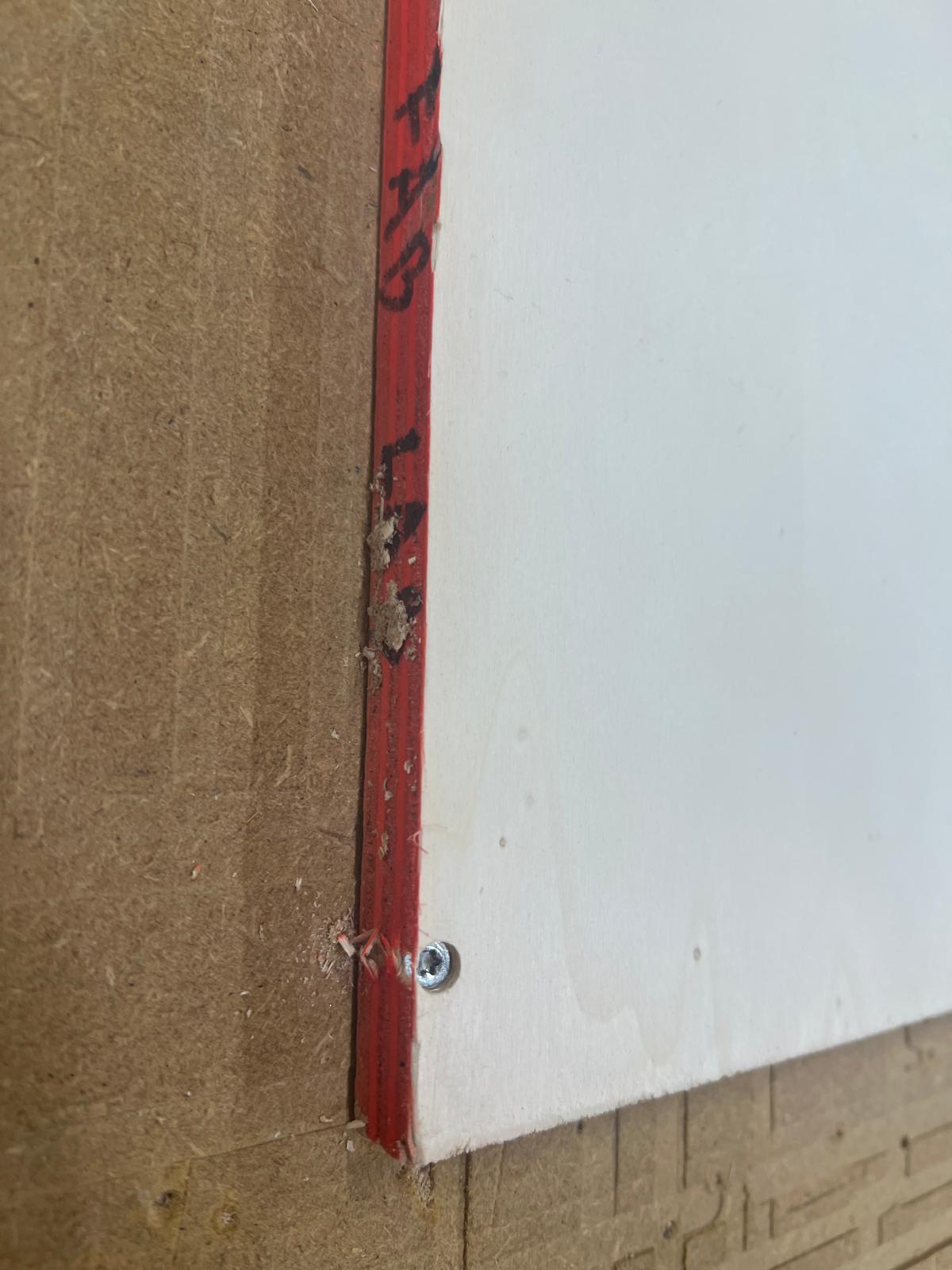
So, now that this was done I uploaded the sliced cutting path file and one could see the path in Kinetic
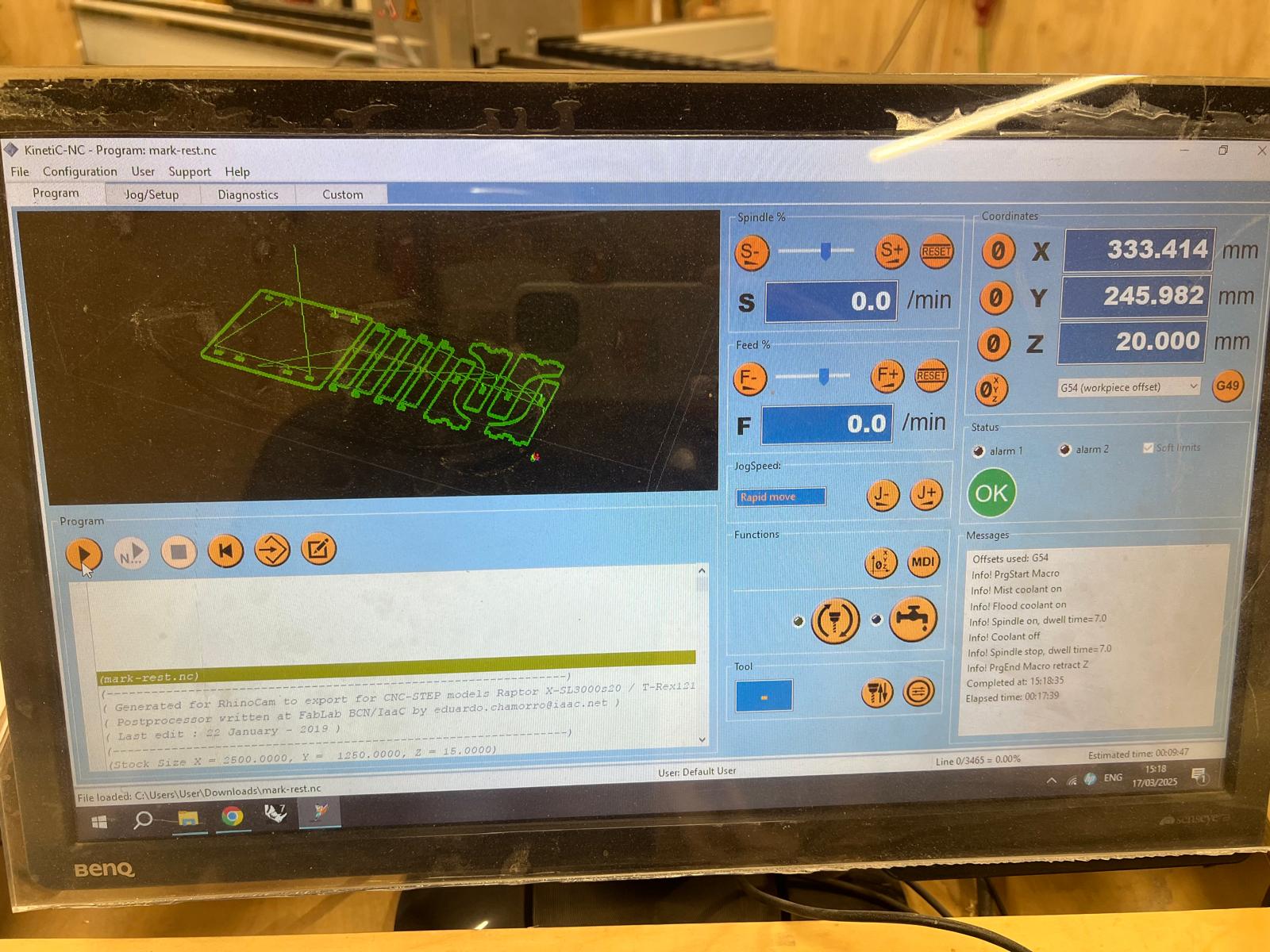
After pressing play the machine starts cutting. From the control table we can see the G code running as well as the programmed toolpath.
and for those into toolpath and Gcode porn, an encore
Cutting pockets:
And outlines
And back to pockets again because I enjoyed it
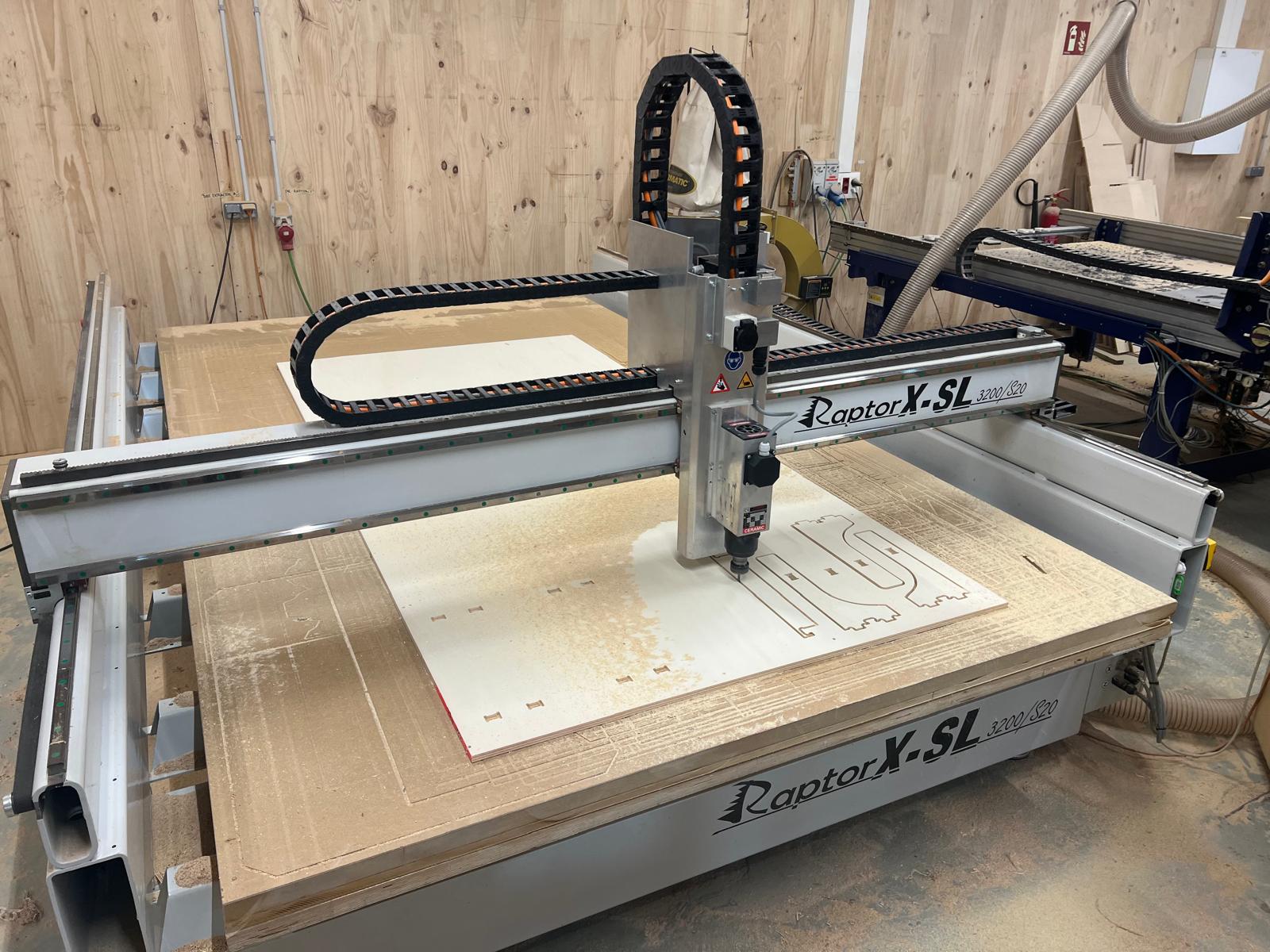
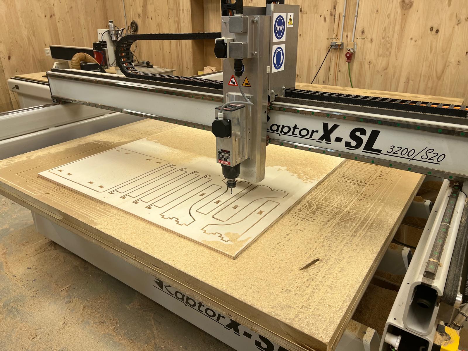
Once the milling finishes I use the high pressure air blaster to clean the area from sawdust so its in a good condition for the next person who uses it.
After this I get my hammer and chisel and gently loosen the pieces and pop them out…and le voila
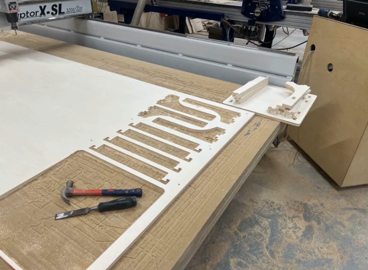
After removing all the pieces I unscrewed the remaining material from the CNC bed, removed the material and placed it back into the stock of material.
After that I took the pieces to my classroom who were very kind and admired my first ever piece of furniture. The photo features my Argentine classmate Simsi admiring the table.
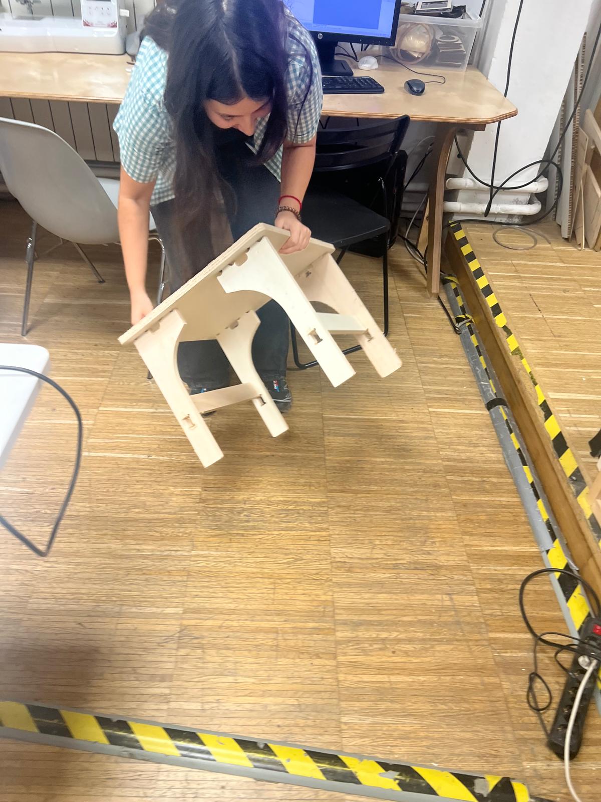
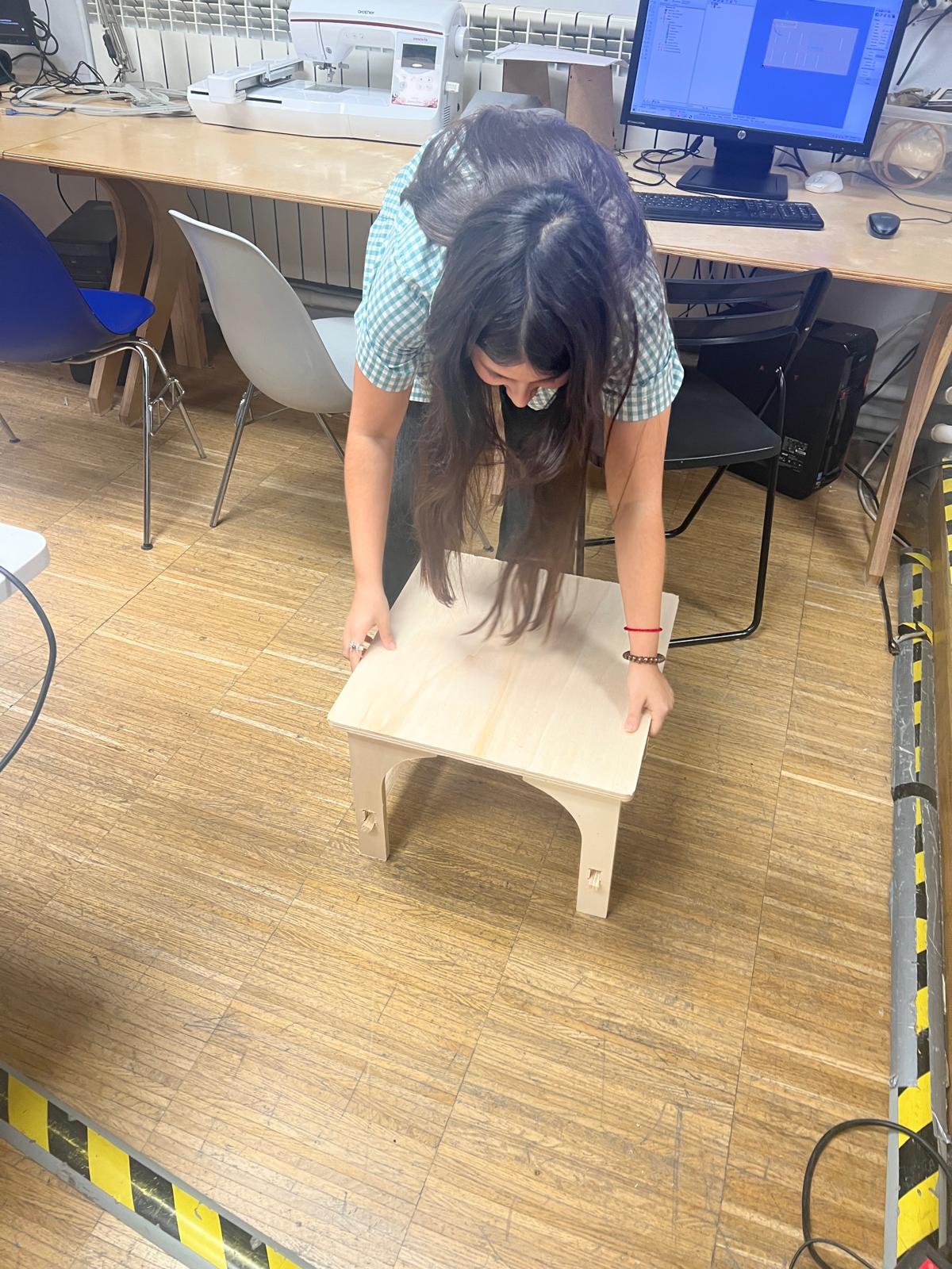
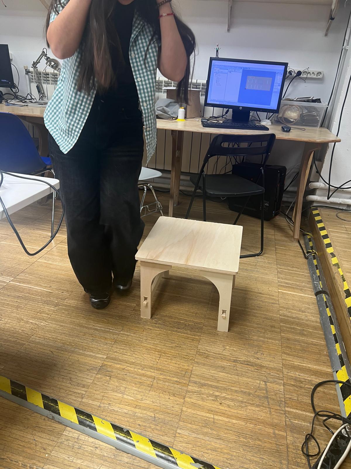
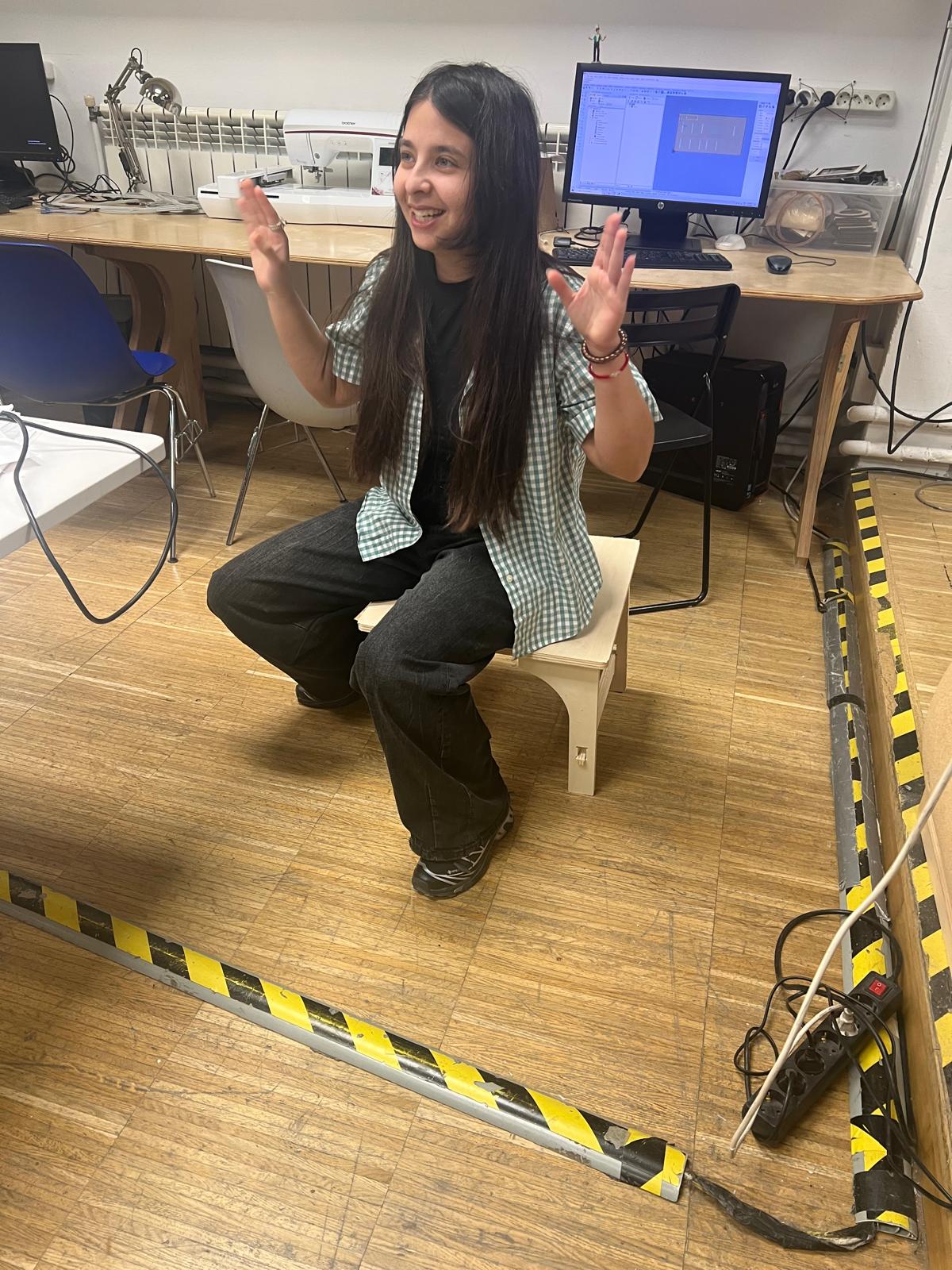
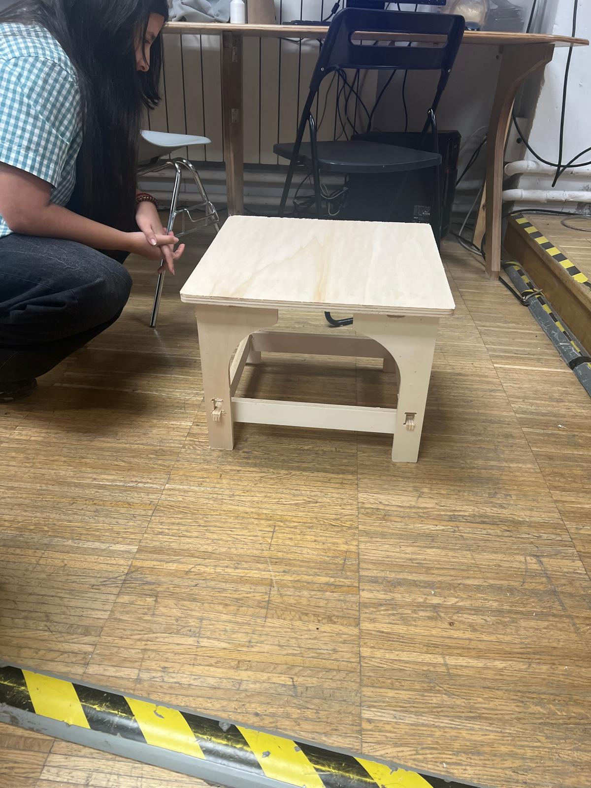
Since the small table was created two weeks have passed and I have been working hard on a standing desk.