Week 04: Embedded Programming
Assignment
Group Assignment
View our group assignment documentation
Individual Assignment
- Browse through the datasheet for your microcontroller
- Write a program for a microcontroller, and simulate its operation
Understanding the Microcontroller
The ESP32-S3 is our chosen type of microcontroller (view datasheet). It is effectively a small computer on a single chip that can be used in smart devices, robots, and IoT (Internet of Things) applications.
A Closer look at the MCU data sheet sections
SECTION 1: ESP32-S3 Series Comparison
This section explains the different versions of the ESP32-S3 chip. There will be a section called 'Nomenclature' which explains the different names. In this case ESP32-S3 chips have different names, such as ESP32-S3FN8 or ESP32-S3R8V. The letters and numbers in these names have meaning:
- ESP32-S3 → The base model (ESP = Espressif, the company that makes these chips)
- F → The chip has built-in flash memory (storage space for programs)
- R → The chip has built-in PSRAM (extra RAM, which is temporary memory for running programs)
- N or H → This tells us the temperature range the chip can handle:
- N = Normal temperature
- H = High temperature
- V → If present, this means the chip only works with 1.8V power supply (instead of the normal 3.3V)
SECTION 2: Pins (Connections)
All chips have pins. These are the contact points that connect to other electronics. This section tells us about the Pin Layout:
ESP32-S3

Bardiuno 4.0.2

The diagrams shows the pin locations. Pins can be inputs (receiving signals) or outputs (sending signals). In the case of the Pin Overview, the sheet shows that ESP32-S3 has 45 GPIO (General-Purpose Input/Output) pins. GPIO means General-Purpose Input/Output and they can be controlled in the code. There are other pins such as ADC (Analog-to-Digital Converter). These allow the chip to read analog signals (like sensor values). There is a PWM pin. This stands for Pulse-Width Modulation. It is used for controlling things like LED brightness or motor speed.
There are also pins for SPI, I2C, UART. They are communication interfaces that allow the chip to talk to other devices. For example the Barduino has a temperature sensor which is built in, but for the ESP32 we would typically connect an IC2 Temperature sensor to the proper pin, and the output would belong to another pin (GPIO). So we need to check the pins that are available and whether the functions they support meet our needs.
SECTION 3: Power and Boot
We also look at the Power Supply section which tells us how to power the ESP32-S3. In the ESP32 document it tells us that the important Power Pins are VDD3P3 which needs 3.3V, and we need to know this to prevent damage to the chip.
When the ESP32-S3 turns on, it needs to know where to load its program from. This is called the boot mode. In the case of the ESP32 we learn that the chip runs its program from flash memory and it also allows us to upload a new program via USB or UART if we need to in certain situations.
SECTION 4: Functional Description
The data sheet gives us a functional description. It explains how the ESP32-S3 works inside, and tells us the system components, and microprocessor. In the case of the ESP32 we learn that it has a dual core, meaning it can do two things at once. It tells us that the clock speed is 240 MHz, and about the ROM (memory used for the boot), RAM (memory for running programs) and PSRAM (extra memory).
Peripherals and Wireless Communication
These are the built in modules that allow the ESP32-S3 to connect to other devices. For example, UART, I2C, SPI (Different ways to communicate with other chips or sensors), PWM (Controls motors, LEDs), USB OTG (On-The-Go) (Lets the ESP32-S3 act as a USB device) and LCD & Camera Interface (Lets us connect a small screen or camera).
The ESP32-S3 has built-in Wi-Fi and Bluetooth. The data sheet tell us that the connection is 2.4 GHz Wi-Fi (802.11b/g/n) and I understood that it can connect to most Wi-Fi networks. The max speed of150 Mbps represents the highest speed possible in perfect conditions which shows how good the performance could be. The Bluetooth is 5.0 in the ESP32, which is good for low-power devices and mesh networking capability (can connect multiple Bluetooth devices together).
Circuit Basics
I am using Sparkfun to learn some basics and summarise here.
A power source has a certain amount of volts. Voltage is potential, but electricity needs to flow to do anything useful. Electricity needs a path to flow through, which must be an electrical conductor such as copper wire. Electricity will flow from a higher voltage to a lower voltage. DC voltage sources always have two sides, called positive and negative, with the positive side a higher voltage than the negative side.
In a simple example, a battery with +12V on one side and 0V on the other creates this voltage difference, causing electrons to move from the negative terminal (low potential) toward the positive terminal (high potential). However, for continuous flow, these electrons must return to the high voltage side. The key lies in the power source, which re-energizes the electrons using stored energy. In a battery, chemical reactions push the electrons back to the high voltage side, ensuring the cycle continues.
Simple Circuit Example
If we connect the positive side of a voltage source, through a resistor (to dampen down the energy, and then on to a Light Emitting Diode (LED), and back to the negative side of the voltage source; electricity, or current, will flow. This circular path is called a circuit.
Arduino Programming
Before diving deep into electronics, I started with some programming examples from the Arduino example page. I chose the Blink example as I remembered Daniel started with that in class.
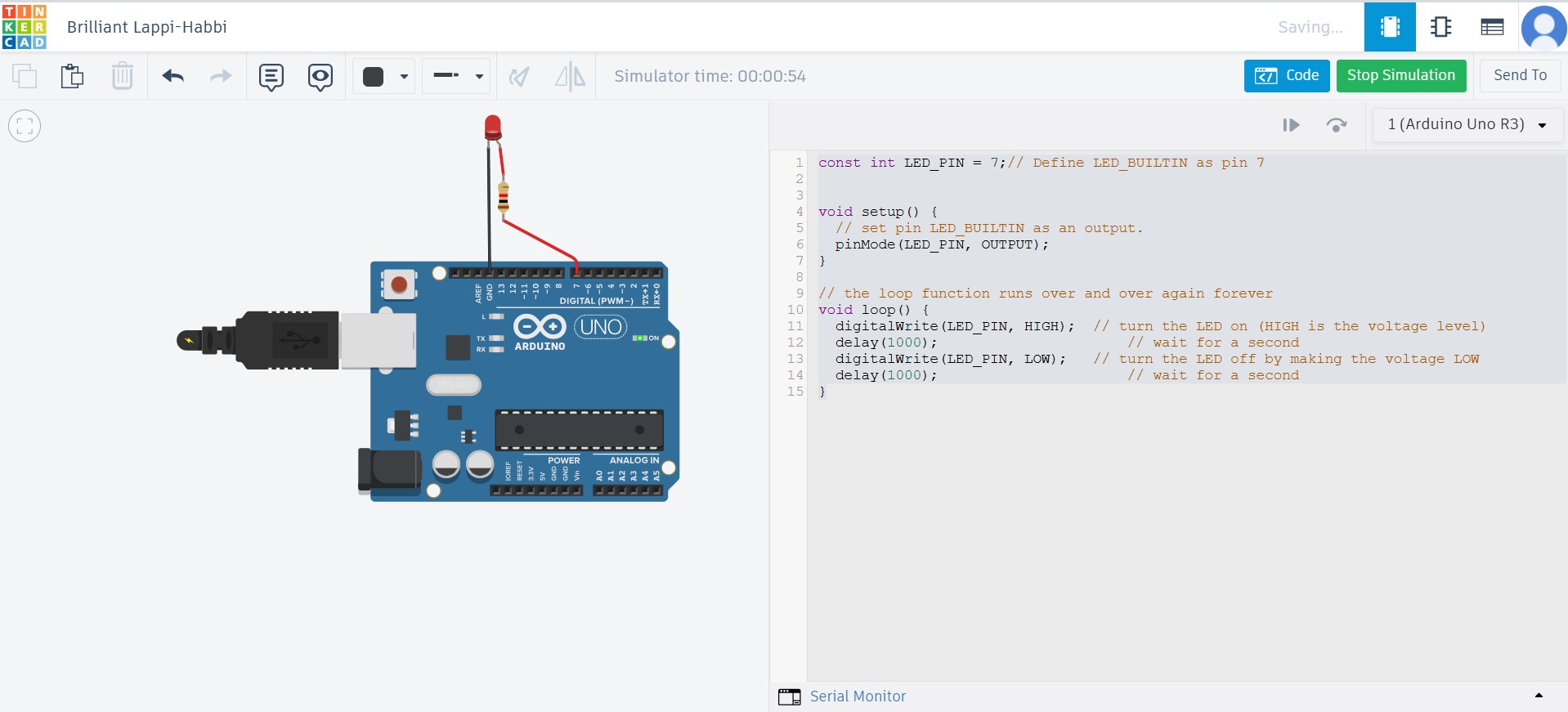
To light an external LED with an Arduino microcontroller we need to build a simple circuit with an LED and a resistor. The resistor limits the current to protect both the LED and the microcontroller.
const int LED_PIN = 7;// Define LED_PIN as pin 7

void setup() {
    // set pin LED_PIN as an output.
    pinMode(LED_PIN, OUTPUT); // Initialize PIN 7 as an output pin
}

void loop() { // the loop function runs over and over again forever
    digitalWrite(LED_PIN, HIGH);  // This supplies 5Volts to the LED anode to turn the LED on (HIGH is the voltage level)
    delay(1000);                  // This commands the board to do nothing for 1000milis (1 second)
    digitalWrite(LED_PIN, LOW);   // This takes the LED_PIN back to 0 volts, turning the LED off.
    delay(1000);                  // wait for a second
}
This code resulted in the light blinking ON and OFF
Red and Green LED Blinking
I then tried this after Blink, and it was too much of a jump for me. It introduced more complicated coding because Delay() stops the Arduino from doing anything where has the Function Millis() allows the Arduino to continue its operations while pausing. So I had an idea to move on to create a Red Blink, followed by a Green blink followed by no Blink and repeat.
I altered the circuit adding a new light and resistor, changed the original blink code and after a few moments it worked. It was very intuitive. I got very minor assistance from Chatgpt.

Arduino Lessons
I want to go through some lessons with Paul McWhorter to get an understanding of how the Barduino that Josep Marti created works.
In lesson 1 & lesson 2 I switched on an LED pin, got it to blink, and also blink with a wait time that has been created as a variable; blinked the light with a different wait time for on and for off and easily able to change by declaring variables.

In lesson 3, Paul introduces two lights, and getting us to change the blinking speed of each, then to create a 'for loop' and a 'counter' where we can make one of the lights blink a few times, before moving to blink the other. Here is the code for blinking the red light twice for 0.7 of a second, then blink the yellow light twice for 2.7seconds:
int LEDPin1=7;
int LEDPin2=6;
int TimeOn_7=700;
int TimeOff_7=700;
int TimeOn_6=2700;
int TimeOff_6=700;
int RedBlinks=2; //number of times to blink red LED
int YellowBlinks=5; //number of times to blink yellow LED

void setup()
{
    pinMode(LEDPin1,OUTPUT);  // put your setup code here, to run once:
    pinMode(LEDPin2,OUTPUT);
}

void loop()
{
    // put your main code here, to run repeatedly:
    for(int j=1; j<=RedBlinks; j=j+1)
    {
        digitalWrite(LEDPin1,HIGH);
        delay(TimeOn_7);
        digitalWrite(LEDPin1,LOW);
        delay(TimeOff_7);
    }

    for(int jy=1; jy<=YellowBlinks; jy=jy+1)
    {
        digitalWrite(LEDPin2,HIGH);
        delay(TimeOn_6);
        digitalWrite(LEDPin2,LOW);
        delay(TimeOff_6);
    }
}
File: week04_Tinkercad4_forloop_counter_blink.brd
At this stage I'd like to go further in my experimentation and perhaps relate it to my final project but my Barduino is having issues connecting to my computer. I need to wait to see Josep on Monday to get it all working.
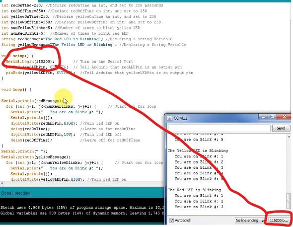
Going through Lesson 4 of Paul McWhorter's Arduino primer, we learn about sending data from the Arduino to print things on the screen to give us information. To talk to the Arduino we already have a cable connected but need to switch on a Serial port. We send something over the port with commands Serial.print or Serial.println. The former prints the same line and latter prints to the next line.
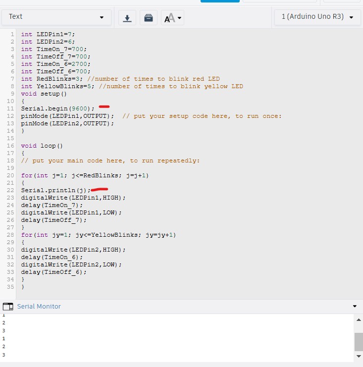
Here, I marked in red where I initialized the serial port once, so under void setup, and then under the loop and red blinks I asked it to print new lines to let me know how many times its flashing. In this example the code tells the Red LED to blink 3 times and the YELLOW Led to print 5 times.
int LEDPin1=7;
int LEDPin2=6;
int TimeOn_7=700;
int TimeOff_7=700;
int TimeOn_6=2700;
int TimeOff_6=700;
int RedBlinks=3; //number of times to blink red LED
int YellowBlinks=5; //number of times to blink yellow LED

void setup()
{
    Serial.begin(115200);
    pinMode(LEDPin1,OUTPUT);  // put your setup code here, to run once:
    pinMode(LEDPin2,OUTPUT);
}

void loop()
{
    Serial.println("The RED LED is blinking!");
    for(int j=1; j<=RedBlinks; j=j+1)
    {
        Serial.print("   You are on Blink #: ");
        Serial.println(j);
        digitalWrite(LEDPin1,HIGH);
        delay(TimeOn_7);
        digitalWrite(LEDPin1,LOW);
        delay(TimeOff_7);
    }

    Serial.println(" ");
    Serial.println("The YELLOW LED is blinking!");
    for(int jy=1; jy<=YellowBlinks; jy=jy+1)
    {
        Serial.print("   You are on Blink #: ");
        Serial.println(jy);
        digitalWrite(LEDPin2,HIGH);
        delay(TimeOn_6);
        digitalWrite(LEDPin2,LOW);
        delay(TimeOff_6);
    }
}
String Manipulation and User Input
In lesson 5, declaring strings and concatenation was explained.
int LEDPin1=7;
int LEDPin2=6;
int TimeOn_7=700;
int TimeOff_7=700;
int TimeOn_6=2700;
int TimeOff_6=700;
int RedBlinks; //number of times to blink red LED
int YellowBlinks; //number of times to blink yellow LED
String redMessage="The RED LED is blinking!";
String yellowMessage="The YELLOW LED is blinking!";

void setup()
{
    Serial.begin(115200);
    pinMode(LEDPin1,OUTPUT);
    pinMode(LEDPin2,OUTPUT);

    Serial.println(" ");
    String welcomemessage1= "Welcome to ";
    String welcomemessage2= "my program";
    String welcomemessage3;
    welcomemessage3=welcomemessage1+welcomemessage2;
    Serial.println(welcomemessage3);
}

void loop()
{
    //block prompt
    Serial.println(" ");
    Serial.println("How many times do you want the RED LED to blink? ");
    while (Serial.available()==0) {} //wait for user input
    RedBlinks = Serial.parseInt();

    //block prompt
    Serial.println("How many times do you want the YELLOW LED to blink? ");
    while (Serial.available()==0) {}
    YellowBlinks = Serial.parseInt();

    Serial.println(redMessage);
    Serial.println(" ");
    for(int j=1; j<=RedBlinks; j=j+1)
    {
        Serial.print("   You are on Blink #: ");
        Serial.println(j);
        digitalWrite(LEDPin1,HIGH);
        delay(TimeOn_7);
        digitalWrite(LEDPin1,LOW);
        delay(TimeOff_7);
    }

    Serial.println(" ");
    Serial.println(yellowMessage);
    Serial.println(" ");
    for(int jy=1; jy<=YellowBlinks; jy=jy+1)
    {
        Serial.print("   You are on Blink #: ");
        Serial.println(jy);
        digitalWrite(LEDPin2,HIGH);
        delay(TimeOn_6);
        digitalWrite(LEDPin2,LOW);
        delay(TimeOff_6);
    }
}
In lesson 6, we look at how to get data from the screen to the Arduino. So in English language, instead of having the number of blinks predetermined in the code and for the user to be fiddling in your code, we will create a situation where a user can input them in the serial monitor and that alters the code. So how do we get data from the serial port? We have to prompt the user with a while (serial.available() ==0) {}. In essence it is waiting for a user input on how many times a user wants the light to blink. Then we need the code to read the answer. So we take the variable for the red blink RedBlinks and we set it at what someone types into the serial port.
int LEDPin1=7;
int LEDPin2=6;
int TimeOn_7=700;
int TimeOff_7=700;
int TimeOn_6=2700;
int TimeOff_6=700;
int RedBlinks; //number of times to blink red LED
int YellowBlinks; //number of times to blink yellow LED
String redMessage="The RED LED is blinking!";
String yellowMessage="The YELLOW LED is blinking!";

void setup()
{
Serial.begin(115200);
pinMode(LEDPin1,OUTPUT);  // put your setup code here, to run once:
pinMode(LEDPin2,OUTPUT);

Serial.println(" ");
String welcomemessage1= "Welcome to ";
String welcomemessage2= "my program";
String welcomemessage3;
welcomemessage3=welcomemessage1+welcomemessage2;
Serial.println(welcomemessage3);
}

void loop() // put your main code here, to run repeatedly:
{
//block prompt
Serial.println(" ");
Serial.println("How many times do you want the RED LED to blink? ");
while (Serial.available()==0) {} //  if ==0 this tests to see if serial avaialble is set to 0 or did someone reply?
//So this program will keep looping until a person enters something
RedBlinks = Serial.parseInt(); //this is saying go to serial port and read the number from the port. So that reads what someone puts in

//block prompt
Serial.println("How many times do you want the YELLOW LED to blink? ");
while (Serial.available()==0) {}
YellowBlinks = Serial.parseInt();

Serial.println(redMessage);
Serial.println(" ");
for(int j=1; j<=RedBlinks; j=j+1)
{
Serial.print("   You are on Blink #: ");
Serial.println(j);
digitalWrite(LEDPin1,HIGH);
delay(TimeOn_7);
digitalWrite(LEDPin1,LOW);
delay(TimeOff_7);
}

Serial.println(" ");

Serial.println(yellowMessage);
Serial.println(" ");
for(int jy=1; jy<=YellowBlinks; jy=jy+1)
{
Serial.print("   You are on Blink #: ");
Serial.println(jy);
digitalWrite(LEDPin2,HIGH);
delay(TimeOn_6);
digitalWrite(LEDPin2,LOW);
delay(TimeOff_6);
}
}
In lesson 7, Paul discusses While loops and said that For and While loops were essential to know. While loops allow continuous execution as long as a condition remains true. It's very useful but getting quite dense and theoretical with all the code and not applying it directly to a goal.
I hope to get the Barduino working on Monday so I can experiment with the sensors.
MCU Comparison and Temperature Sensing
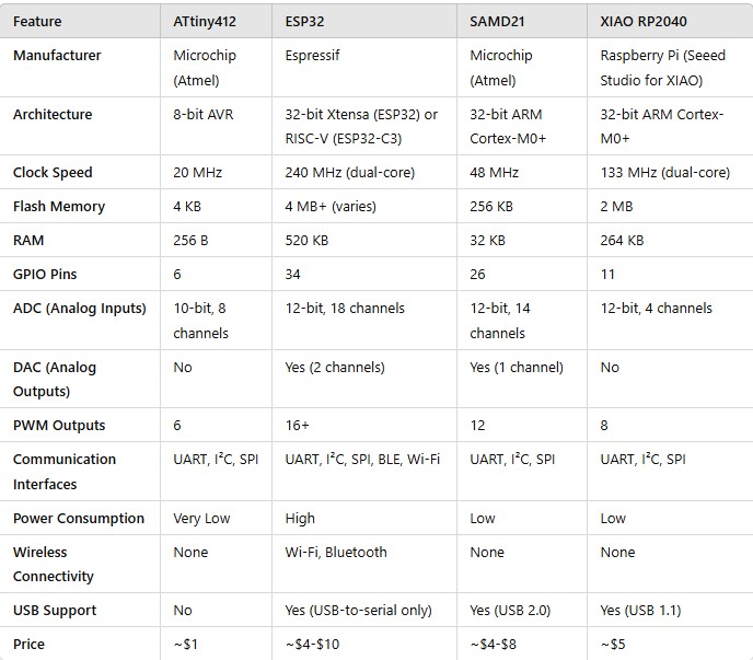
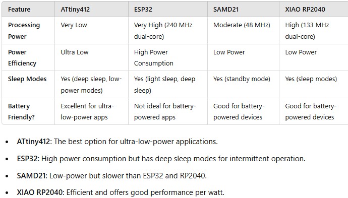
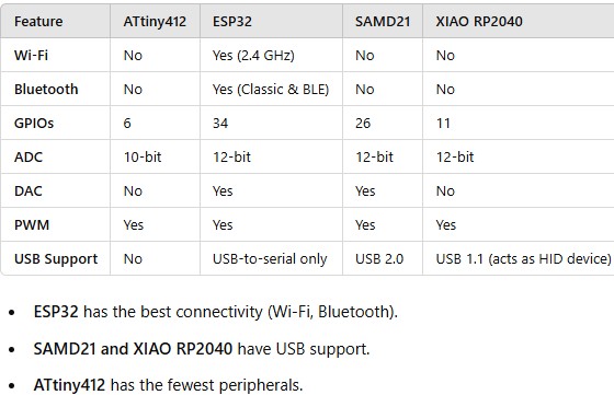
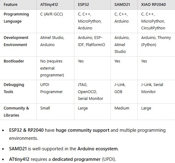
On 02/18/25, we had the MCU(Microcontroller Unit) class with Josep and Dani where they explained different types of chips and their architectures and purposes. The chips we focused on were the ATtiny412, ESP32, SAMD21, and XIAO RP2040. We covered architecture, performance, power consumption & peripherals, development tools, and best use cases.
Comparative Analysis
Using my class notes and some prompting to Chatgpt, I did a comparative analysis of the 4 architectures:
General Architecture:
Performance and Power Consumption:
Peripherals and Connectivity:
Development Tools and Ecosystem:
Summary and Conclusions

Temperature Sensor Implementation
I was finally able to get my Barduino working thanks to Josep and I tried out a script with the help of Chatgpt:
#include

#define TMP102_ADDRESS 0x48  // Your sensor's I2C address

void setup() {
    Serial.begin(115200);
    Wire.begin();  // Start I2C communication
}

void loop() {
    Wire.beginTransmission(TMP102_ADDRESS);  // Start communication with sensor
    Wire.write(0x00);  // Set pointer to temperature register
    Wire.endTransmission();

    Wire.requestFrom(TMP102_ADDRESS, 2);  // Request 2 bytes of data

    if (Wire.available() >= 2) {
        byte MSB = Wire.read();  // Read most significant byte
        byte LSB = Wire.read();  // Read least significant byte

        int16_t tempData = ((MSB << 8) | LSB) >> 4;  // Convert to 12-bit value

        float temperature = tempData * 0.0625;  // Each step = 0.0625°C

        Serial.print("Temperature: ");
        Serial.print(temperature);
        Serial.println(" °C");
    } else {
        Serial.println("Error reading temperature!");
    }

    delay(2000);  // Wait 2 seconds before next reading
}
Barduino Exercises with Daniel
Daniel Mateos created some exercises using Barduino. You can find the pinout documentation here.
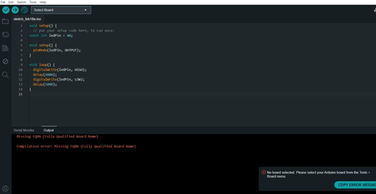
One cannot just copy the code or will get the following error:
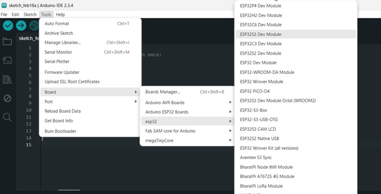
We need to load the board that we are using:
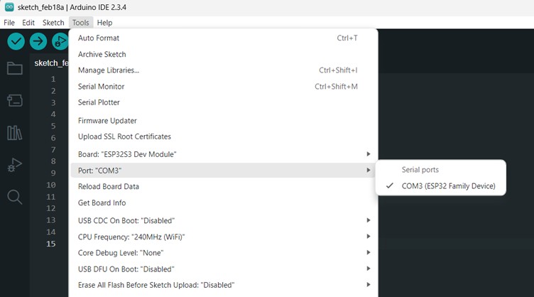
And the port number:
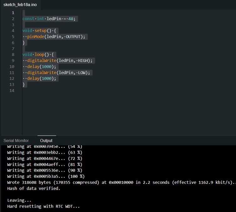
const int ledPin = 48;

void setup() {
    pinMode(ledPin, OUTPUT);
}

void loop() {
    digitalWrite(ledPin, HIGH);
    delay(1000);
    digitalWrite(ledPin, LOW);
    delay(1000);
}
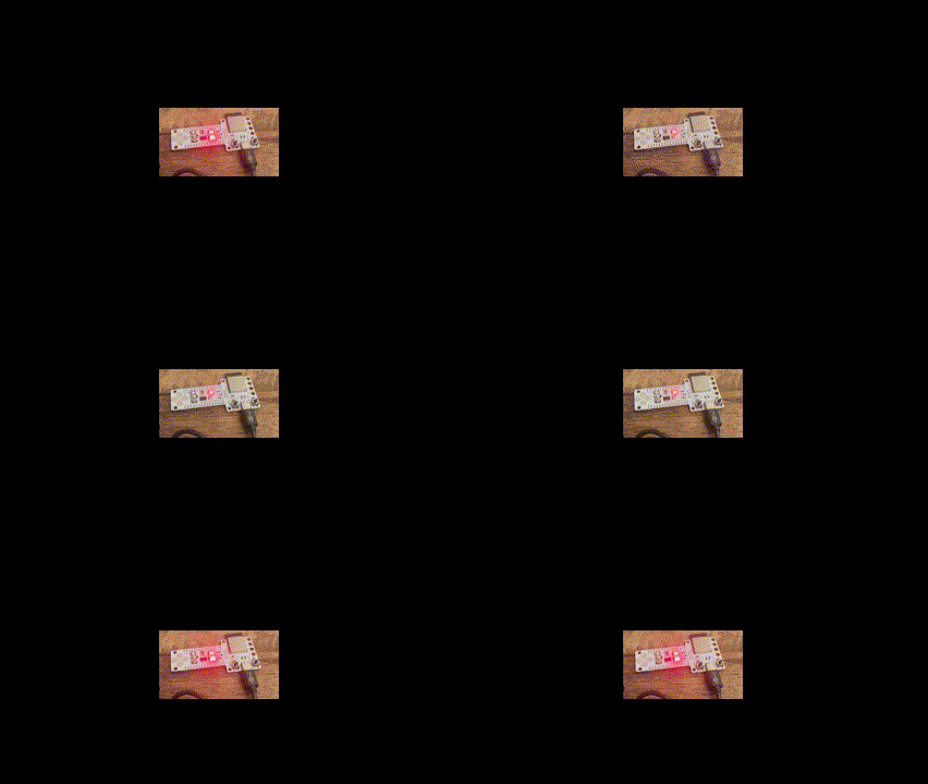
Then Daniel asked us to make the light blink 10 times per second, so I changed the delay from 1000 to 100 and it started blinking very fast.
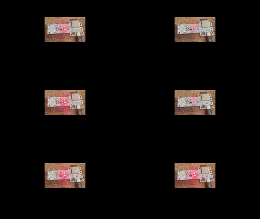
Reading the BOOT Button
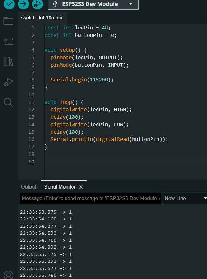
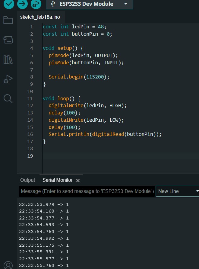
Combining Button and LED Control
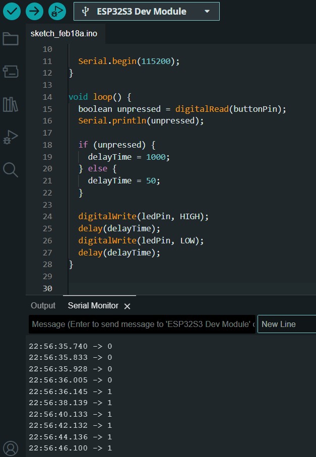
The next exercise was to combine control over the flashing light with an output in the serial monitor. When the BOOT button is not pressed then the light blinks once per second and when it is it flashed at 10x per second. I had trouble with this as simple as it is. Eventually I looked at Dani's hints and then went to Chatgpt to have each code line fully explained.
const int ledPin = 48;
const int buttonPin = 0;

int delayTime = 1000;

void setup() {
    pinMode(ledPin, OUTPUT);
    pinMode(buttonPin, INPUT);

    Serial.begin(115200);
}

void loop() {
    boolean unpressed = digitalRead(buttonPin);
    Serial.println(unpressed);

    if (unpressed) {
        delayTime = 1000;
    } else {
        delayTime = 50;
    }

    digitalWrite(ledPin, HIGH);
    delay(delayTime);
    digitalWrite(ledPin, LOW);
    delay(delayTime);
}
Chirpy Barduino
The next exercise is chirpy Barduino, where we are given the method to create a sound and we are encouraged to create some more sounds. I did so initially and then realised that we could create songs. So I asked chatGpt for the tones and delays for Darth Vader's theme:
int buzzerPin = 46;

void setup() {
    tone(buzzerPin, 440, 500); // A
    delay(550);
    tone(buzzerPin, 440, 500); // A
    delay(550);
    tone(buzzerPin, 440, 500); // A
    delay(550);
    tone(buzzerPin, 349, 350); // F
    delay(400);
    tone(buzzerPin, 523, 150); // High C
    delay(200);

    tone(buzzerPin, 440, 500); // A
    delay(550);
    tone(buzzerPin, 349, 350); // F
    delay(400);
    tone(buzzerPin, 523, 150); // High C
    delay(200);
    tone(buzzerPin, 440, 1000); // A (Hold)
    delay(1050);

    tone(buzzerPin, 659, 500); // E
    delay(550);
    tone(buzzerPin, 659, 500); // E
    delay(550);
    tone(buzzerPin, 659, 500); // E
    delay(550);
    tone(buzzerPin, 698, 350); // F
    delay(400);
    tone(buzzerPin, 523, 150); // C
    delay(200);

    tone(buzzerPin, 415, 500); // G#
    delay(550);
    tone(buzzerPin, 349, 350); // F
    delay(400);
    tone(buzzerPin, 523, 150); // C
    delay(200);
    tone(buzzerPin, 440, 1000); // A
    delay(1050);
}

void loop() {}