
Week 09: Input Devices
Group Assignment
Please click here to see the group work
Individual Assignment
- Measure something: add a sensor to a microcontroller board that you have designed and read it.
This week is all about Input devices…these are hardware used to provide data and control signals to a computer or information processing system like a keyboard, mouse scanner, camera, microphone, light switch or other such device.
Input devices that we come into contact like sensors and buttons can be (to name a few): Proximity, pressure, temperature and humidity, flow and level, alcohol, motion, colour, chemical, vibration, touch, infrared, gas, gyroscope, ultrasonic accelerometer (to measure the orientation of an object, its rate of change, including tap, shake, tilt and positioning), and so many more.
We were given a breadboard, wires and sensors
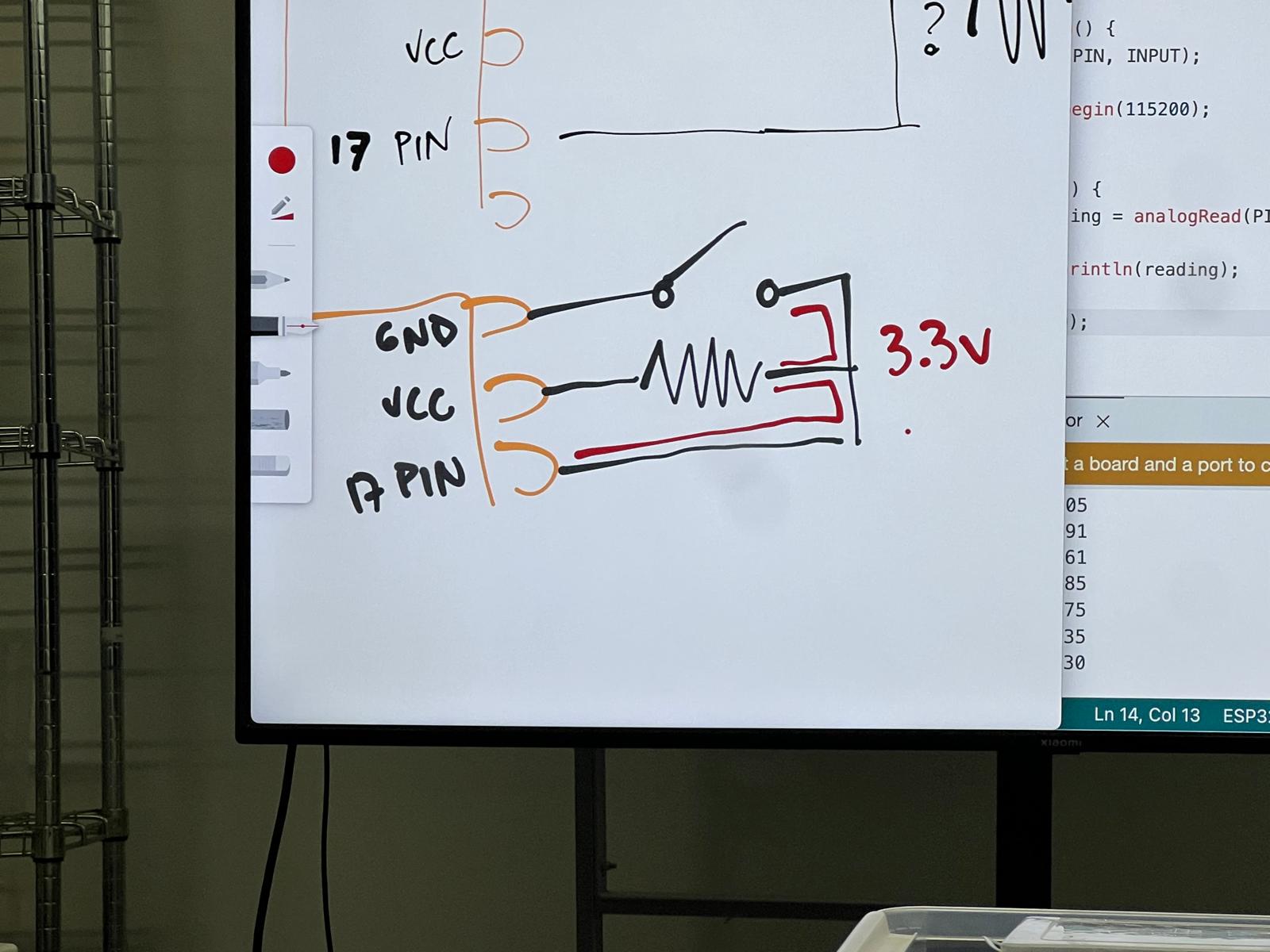
In a closed circuit measuring at ground the Voltage will be 0v. if the circuit is open then the voltage will be undefined. We connect basic breadboard circuit – and made a light flash when button pressed
We used multimeter to look at the voltage around the circuit
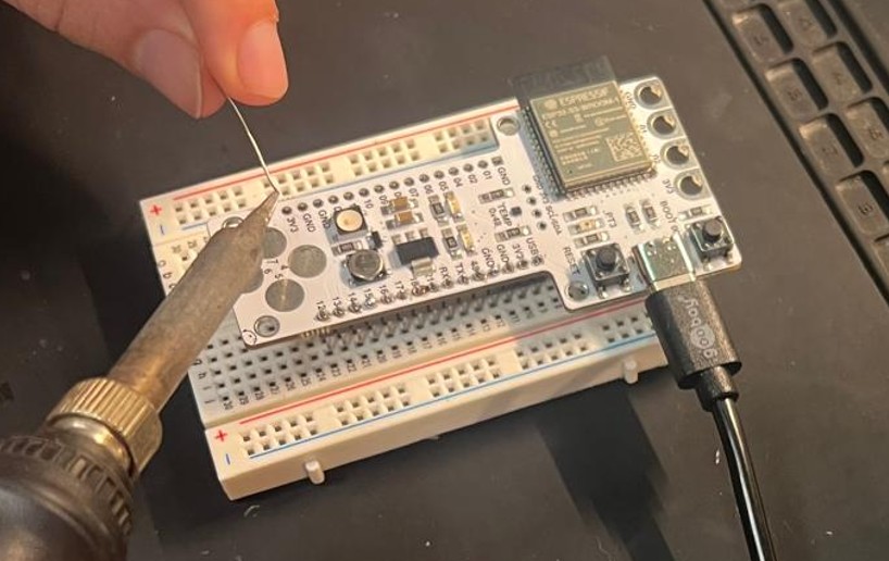
Then we went down to the lab and soldered pin connectors into both sides of a barduino and then put the barduino into the breadboard
Then I wrote a simple code analog read the pin
#define PIN 17

void setup() {
    pinMode (PIN, INPUT);
    // put your setup code here, to run once:
    Serial.begin(115200);
}

void loop() {
    int reading = analogRead(PIN);
    Serial.println(reading);
    // put your main code here, to run repeatedly:
}
and then ran it…and its giving off random numbers
so we ground it by connecting ground to pin 17 as can be seen in the image
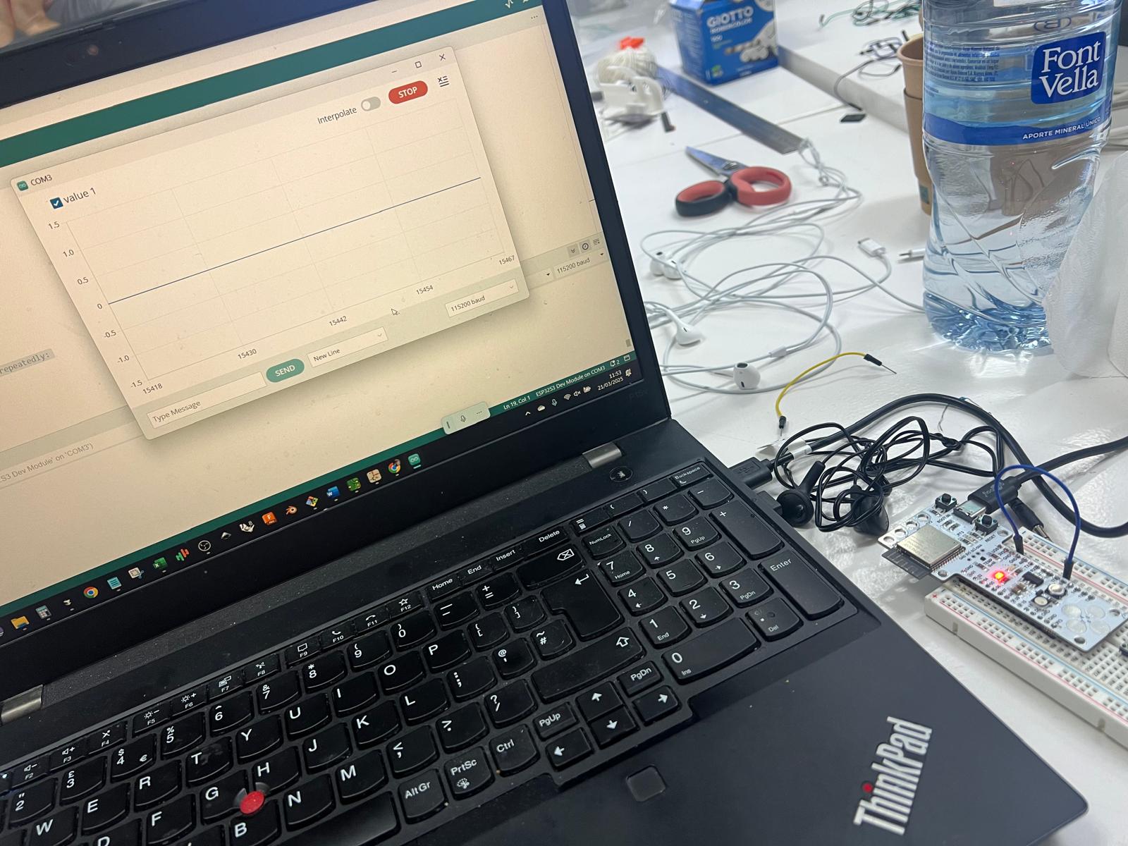
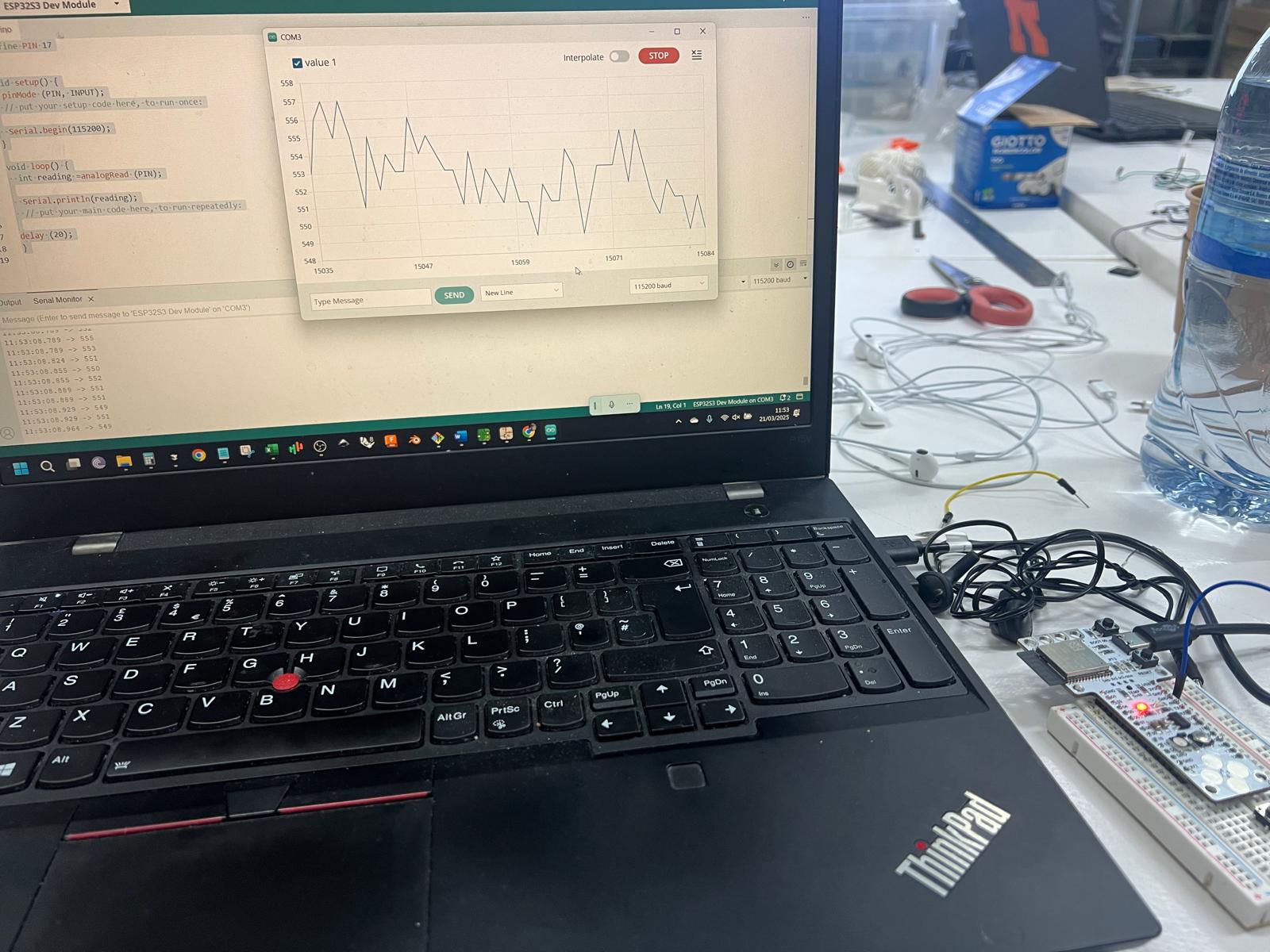
so the circuit is running and when you push button on barduino now it closes circuit and that can be seen with the serial plotter
If we replace analog read with digital read the values change to 0 and 1
With new code it looks at the code and button not pressed reading is 1…..then button is pressed and the reading is 0, then 1, then when I hold it down the reading is 0 at every count until button is released, then reading 1 again – verifying the number of milliseconds the button has been pressed.
#define PIN 17
int prevReading = 0;
int reading = 0;
int timesPressed = 0;

void setup() {
    pinMode (PIN, INPUT);
    // put your setup code here, to run once:
    Serial.begin(115200);
}

void loop() {
    prevReading = reading;
    reading = digitalRead (PIN);

    if(reading == 0) {
        timesPressed = timesPressed + 1;
    }

    Serial.print("reading:");
    Serial.print(reading);
    Serial.print(" timesPressed:");
    Serial.println(timesPressed);

    delay(1);
}
Then in the next code, the serial port counts the number of times the button is pressed.
#define PIN 17
int prevReading = 0;
int reading = 0;
int timesPressed = 0;

void setup() {
    pinMode (PIN, INPUT);
    // put your setup code here, to run once:
    Serial.begin(115200);
}

void loop() {
    prevReading = reading;
    reading = digitalRead (PIN);

    if(prevReading == 1 && reading == 0) {
        timesPressed = timesPressed + 1;
    }

    Serial.print("reading:");
    Serial.print(reading);
    Serial.print(" timesPressed:");
    Serial.println(timesPressed);

    delay(1);
}
Moving on to a new input device – how a potentiometer works? It is like a variable resistor and it is essentially the technical name for a volume knob type input device – (an infinite one that keeps turning is called a rotary encoder)
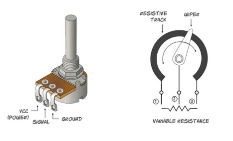
One can set values for a potentiometer, so each movement or click corresponds to a particular output. It could be analog or digital meaning, like an analog volume not or perhaps a digital one with preset increments.
In the following video one can see the potentiometer control on the monitor reading as analog:
Now measuring the resistance of a light sensor when adding light the resistance decreases and when reducing light resistance is increased and this is the code
void setup() {
    pinMode (17, INPUT);
    // put your setup code here, to run once:
    Serial.begin(9600);
}

void loop() {
    int lecture = analogRead (17);
    Serial.println(lecture);
    delay(50);
}
Next we are going to measure a sensor individually so I am using the pir….
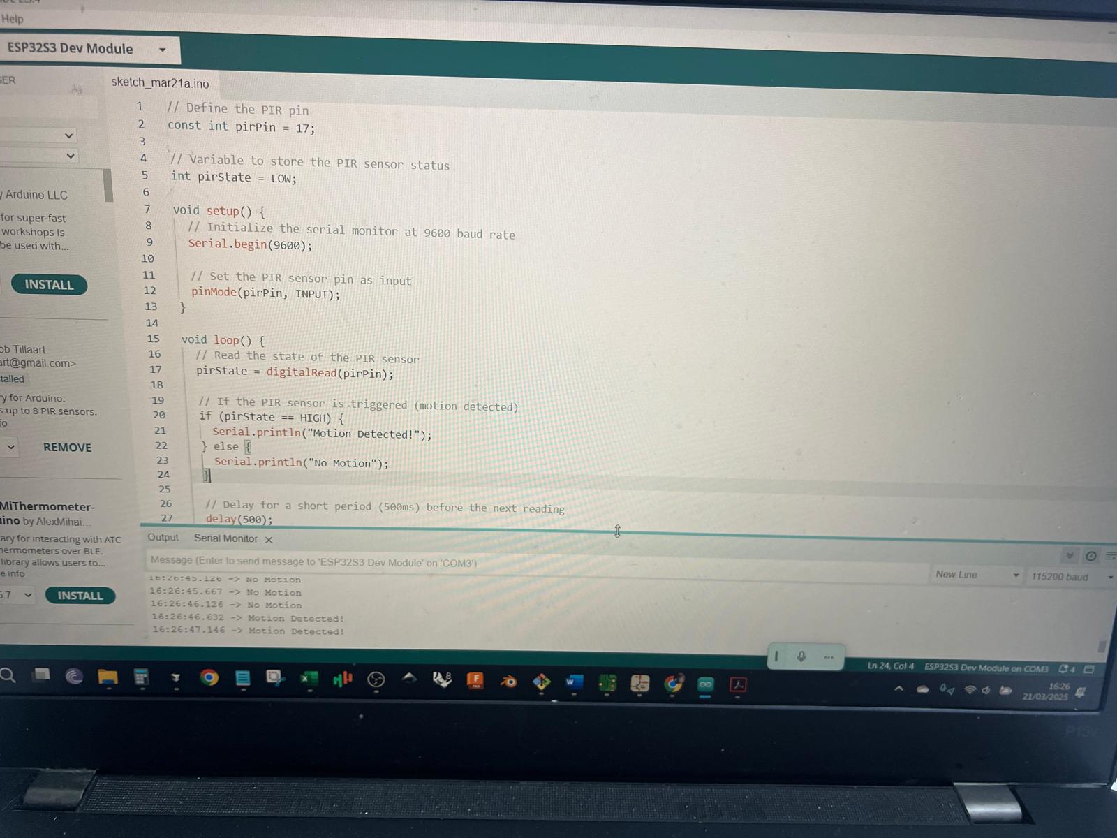
with the code below it showed motion detection but the light didn't change – it just stayed on
// Define the PIR pin
const int pirPin = 17;
// Variable to store the PIR sensor status
int pirState = LOW;
void setup() {
// Initialize the serial monitor at 9600 baud rate
Serial.begin(9600);
// Set the PIR sensor pin as input
pinMode(pirPin, INPUT);
}
void loop() {
// Read the state of the PIR sensor
pirState = digitalRead(pirPin);
// If the PIR sensor is triggered (motion detected)
if (pirState == HIGH) {
Serial.println("Motion Detected!");
} else {
Serial.println("No Motion");
}
// Delay for a short period (500ms) before the next reading
delay(500);
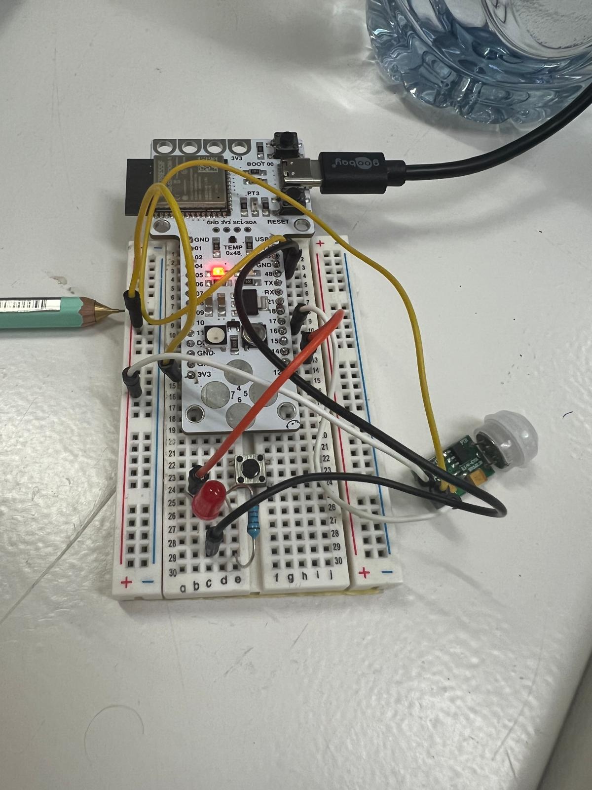
}So after updating the code A FEW times I rewired the LED not to take power directly and instead connected it to PIN 13. It is still not working yet but see updated wiring image
Finally got it to work but it seems slightly buggy and weird reaction times although conditions are not ideal for testing
This was the final code and screenshot. In the embedded video you will really have to squeeze your eyes on the right to see how the LED switches from OFF to ON, and at the same time do some gymnastics by squeezing your eyes left to notice that the serial monitor changed from No Motion detected to Motion Detected!
int pirPin = 17;   // PIR sensor output pin
int ledPin = 13;   // LED pin
int analogPin = A0; // Analog pin (change if needed)

void setup() {
    pinMode(pirPin, INPUT);
    pinMode(ledPin, OUTPUT);
    Serial.begin(9600); // For debugging
    delay(100); // 1 minute delay for sensor stabilization
}

void loop() {
    int pirValue = digitalRead(pirPin); // Read PIR sensor value
    int analogValue = analogRead(analogPin); // Read analog value

    if (pirValue == HIGH) {
        digitalWrite(ledPin, HIGH); // Turn LED on
        Serial.print("Motion Detected! Analog Value: ");
        Serial.println(analogValue); // Print analog value
        delay(100); // Small delay to avoid rapid triggering
    } else {
        digitalWrite(ledPin, LOW);  // Turn LED off
        Serial.print("No Motion. Analog Value: ");
        Serial.println(analogValue); // Print analog value
    }

    delay(50); // Small delay for loop stability
}
April Update - 04/19/25
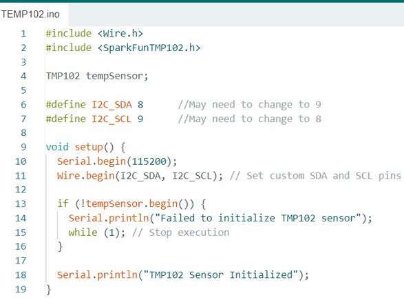
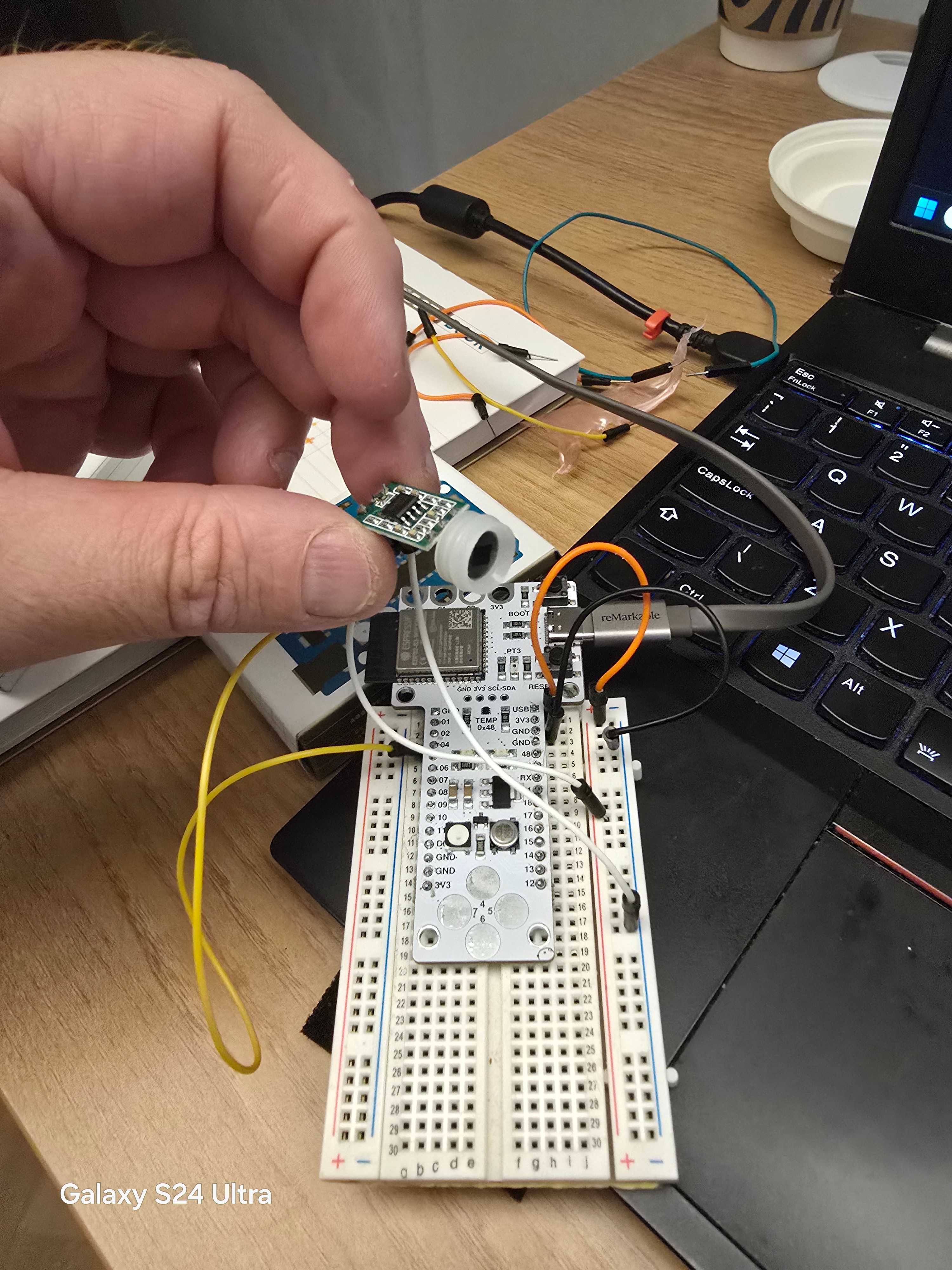
I am looking to experiment with some input and output devices today. On the Barduino using an ESP32 chip there is already a TMP102 temperature sensor connected by I2C.
See the Barduino Pinout and basic information
To read temperature we will use the following libraries in the Arduino IDE:
- Wire.h
- SparkFunTMP102.h
Reading Temperature Code
#include <Wire.h>
#include <SparkFunTMP102.h>
TMP102 tempSensor;
#define I2C_SDA 8 //May need to change to 9
#define I2C_SCL 9 //May need to change to 8
void setup() {
Serial.begin(115200);
Wire.begin(I2C_SDA, I2C_SCL); // Set custom SDA and SCL pins
if (!tempSensor.begin()) {
Serial.println("Failed to initialize TMP102 sensor");
while (1); // Stop execution
}
Serial.println("TMP102 Sensor Initialized");
}
void loop() {
float temperatureC = tempSensor.readTempC();
Serial.print("Temperature: ");
Serial.print(temperatureC);
Serial.println(" °C");
delay(1000); // 1 second delay
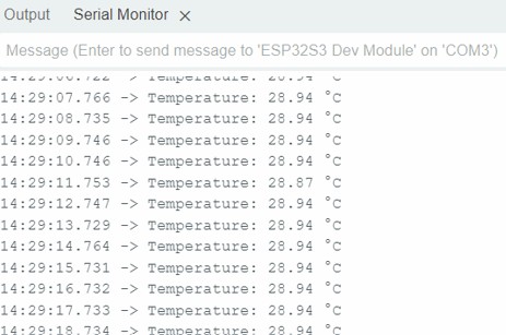
}These photos show the simple code, and the output in the serial monitor for the Barduino.
Making a PIR sensor work again
PIR SENSOR
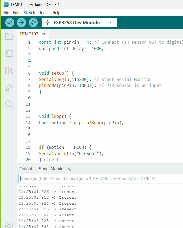
Make sure to switch off the serial monitor before compiling as it can really mess with the functionality
const int pirPin = 4; // Connect PIR sensor OUT to digital pin 2
unsigned int Delay = 1000;

void setup() {
    Serial.begin(115200); // Start Serial Monitor
    pinMode(pirPin, INPUT); // PIR sensor is an input
}

void loop() {
    bool motion = digitalRead(pirPin);

    if (motion == HIGH) {
        Serial.println("Present");
    } else {
        Serial.println("Absent");
    }

    delay(Delay); // Wait 1 second before checking again
}
In the code chatgpt creates unsigned variable which apparently doesn't allow negative numbers to compile in case one makes an error.
The sensor will detect a change in infrared signatures and change its condition from 'absent' to 'present' when a change is detected.
Below one can see both the code and the output change after I waved my hand. The reaction time is not instantaneous – it takes a good few seconds to see the reaction. I want to find out if it is possible to fine tune that reaction time.
Exploring the Ultrasonic Sensor
As i want to try another input device, I am looking at the ultrasonic sensor otherwise known as an ultrasonic transducer.
#define TX_PIN 5 // GPIO5 for Trigger
#define RX_PIN 16 // GPIO18 for Echo
//#define BUZZER 46 // GPIO for Buzzer

void setup() {
    Serial.begin(115200); // Start Serial Monitor
    pinMode(RX_PIN, INPUT); // Set echo as input
    pinMode(TX_PIN, OUTPUT); // Set trigger as output
}

void loop() {
    // Clear the trigger
    digitalWrite(TX_PIN, LOW);
    delayMicroseconds(2);

    // Send a 10 microsecond pulse
    digitalWrite(TX_PIN, HIGH);
    delayMicroseconds(10);
    digitalWrite(TX_PIN, LOW);

    // Read the echo time
    long duration = pulseIn(RX_PIN, HIGH);

    // Convert time to distance (cm)
    float distance = (duration/2) * 0.0343;

    // Print distance
    Serial.print("Distance: ");
    Serial.print(distance);
    Serial.println(" cm");

    delay(500); // Update every 0.5 seconds
}
Now, to build on the Ultrasonic sensor, chatgpt modifies the code so that a very close distance of less than 10cms will trigger a buzzer on the Barduino.
This code is for an Ultrasonic sensor with an active buzzer.
#define TX_PIN 5 // GPIO5 for Trigger
#define RX_PIN 16 // GPIO18 for Echo
#define BUZZER 46 // GPIO for Buzzer

void setup() {
    Serial.begin(115200); // Start Serial Monitor
    pinMode(RX_PIN, INPUT); // Set echo as input
    pinMode(TX_PIN, OUTPUT); // Set trigger as output
    pinMode(BUZZER,OUTPUT); //Connected to onboard Buzzer
}

void loop() {
    // Clear the trigger
    digitalWrite(TX_PIN, LOW);
    delay(2);

    // Send a 10 microsecond pulse
    digitalWrite(TX_PIN, HIGH);
    delayMicroseconds(10);
    digitalWrite(TX_PIN, LOW);

    // Read the echo time
    long duration = pulseIn(RX_PIN, HIGH);

    // Convert time to distance (cm)
    float distance = (duration/2) * 0.0343;

    // Print distance
    Serial.print("Distance: ");
    Serial.print(distance);
    Serial.println(" cm");

    if(distance < 10) {
        digitalWrite(BUZZER, HIGH);
    } else {
        digitalWrite(BUZZER, LOW);
    }

    delay(500); // Update every 0.5 seconds
}
There was no response and the buzzer did not work. So i tested whether a light would shine on pin 48 when distance was <10cm and it did. Since i knew it was working, i kept searching around.
I found there was also a passive buzzer and so i tried the code for that.
#define TX_PIN 5   // Trigger pin (GPIO5)
#define RX_PIN 16  // Echo pin (GPIO16)
#define BUZZER 46  // Passive buzzer pin (connect to GPIO46)

void setup() {
    Serial.begin(115200);
    pinMode(RX_PIN, INPUT);
    pinMode(TX_PIN, OUTPUT);
    pinMode(BUZZER, OUTPUT); // Still needed for tone()
}

void loop() {
    // Clear trigger
    digitalWrite(TX_PIN, LOW);
    delayMicroseconds(2);

    // Send 10µs pulse
    digitalWrite(TX_PIN, HIGH);
    delayMicroseconds(10);
    digitalWrite(TX_PIN, LOW);

    // Read echo
    long duration = pulseIn(RX_PIN, HIGH);

    // Convert to distance (cm)
    float distance = (duration / 2.0) * 0.0343;

    Serial.print("Distance: ");
    Serial.print(distance);
    Serial.println(" cm");

    // Control passive buzzer
    if (distance < 10) {
        tone(BUZZER, 2400); // C5 tone (you can pick 440Hz, 494Hz, etc.)
    } else {
        noTone(BUZZER); // Stop the sound
    }

    delay(500);
}
Just for the sake of information i will paste below the way that i actually found the code. This is what i pasted into chatgpt and the reply it gave me:
THIS IS MY CODE FOR ACTIVE BUZZER
#define TX_PIN 5 // GPIO5 for Trigger
#define RX_PIN 16 // GPIO18 for Echo
#define BUZZER 46 // GPIO for Buzzer

void setup() {
Serial.begin(115200);  // Start Serial Monitor

pinMode(RX_PIN, INPUT); // Set echo as input
pinMode(TX_PIN, OUTPUT); // Set trigger as output
pinMode(BUZZER,OUTPUT); //Connected to onboard Buzzer }

void loop() { // Clear the trigger
digitalWrite(TX_PIN, LOW);
delay(2); // Send a 10 microsecond pulse
digitalWrite(TX_PIN, HIGH);
delayMicroseconds(10);
digitalWrite(TX_PIN, LOW); // Read the echo time long duration =

pulseIn(RX_PIN, HIGH); // Convert time to distance (cm) float distance = (duration/2) * 0.0343; // Print distance
Serial.print("Distance: ");
Serial.print(distance);
Serial.println(" cm");
if(distance < 10) { digitalWrite(BUZZER, HIGH);
}else { digitalWrite(BUZZER, LOW); } delay(500); // Update every 0.5 seconds }

HOW DO I ADAPT PASSIVE BUZZER SCRIPTING TO THE ACTIVE SCRIPT SO THAT I CAN FIT IT INTO A PASSSIVE BUZZER
So you can see that in many cases it is possible to get answers to questions using AI if you know where to guide it. I do get led down a pathway to nowhere plenty of times. I just try and keep the requests as simple and distilled as possible to get the best answers.
Using Input Devices with my SAMD11C development board
/*
AnalogReadSerial
Reads an analog input on pin 0, prints the result to the Serial Monitor.
Graphical representation is available using Serial Plotter (Tools > Serial Plotter menu).
Attach the center pin of a potentiometer to pin A0, and the outside pins to +5V and ground.
This example code is in the public domain.
https://www.arduino.cc/en/Tutorial/BuiltInExamples/AnalogReadSerial
*/
// the setup routine runs once when you press reset:
void setup() {
// initialize serial communication at 9600 bits per second:
Serial.begin(9600);
}
// the loop routine runs over and over again forever:
void loop() {
// read the input on analog pin 0:
int sensorValue = analogRead(A0);
// print out the value you read:
Serial.println(sensorValue);
delay(1); // delay in between reads for stability
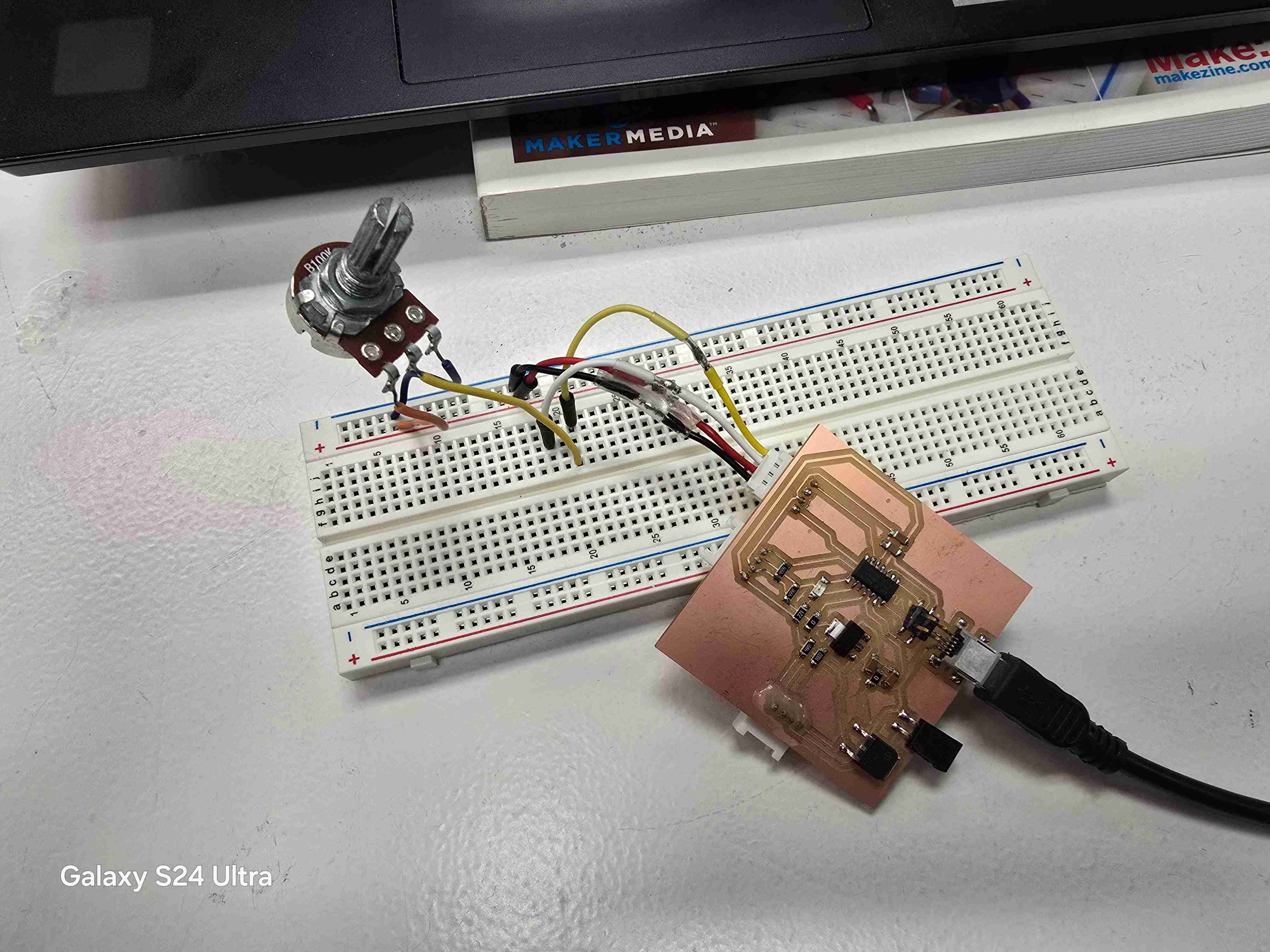
}The following images show the setup. As can be seen the SAMD11c board was connected to the 5v VCC through a USB B port and then via a Grove connector. The VCC to the power rail and the GND to the GND rail and a yellow data connection to a particular row. Then a potentiometer was connected to match the Grove to the GND rail & power rail, and the Data pin was connected to match the data row of the board.
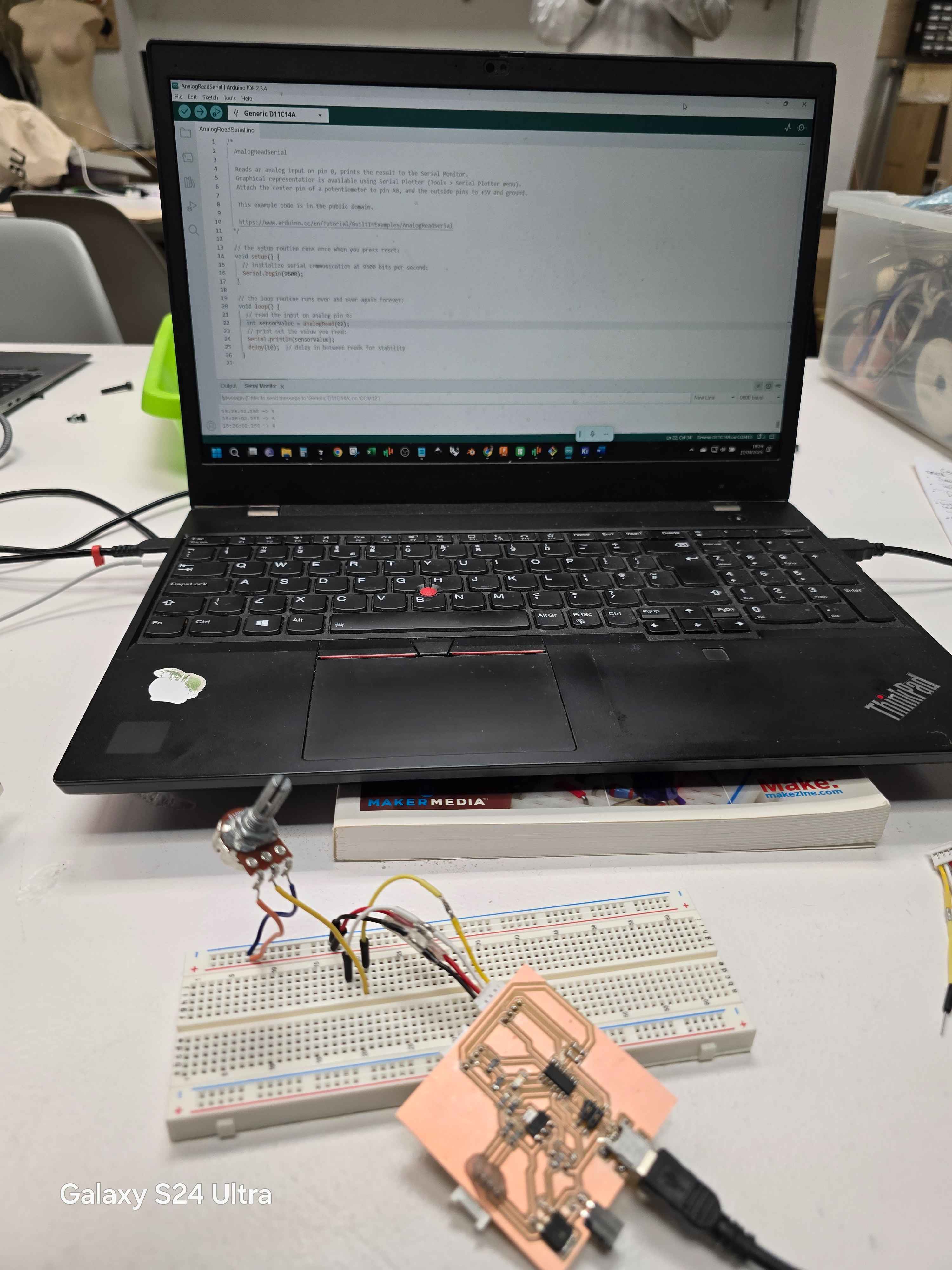
This video shows the potentiometer being manipulated and that the serial monitor shows an increase from roughly 5 to 1005
Reflections
In the week 09 when we were supposed to use input devices with our own development boards, I could not figure out for the life of me how to burn it. When i finally sat with Dani, he helped me to burn it and it was really so straight forward as previously documented in week 08.
So i delayed using an input device, and an output device and then my board broke in my bag. It was a blessing in disguise and I redesigned it to include networking and communications which would be useful for the coursework of week11.
Once this was all done it was extremely straightforward getting my device to work via Arduino code and give readings based on connecting an input device.
I ran a preset program called analog read and it would read the changes in the resistance coming in from potentiometer when it was turned up or down.
As can be seen from the above video it worked easily with changing readings.
It would be simple to use other input devices like the sensors I used with an ESP32 such as Ultrasonic or PIR sensor, and I will try that too when i have a moment - probably with the new board i create.