
Week 14: Interface & Application Programming
Assignment
- Group Assignment: compare as many tool options as possible
- Individual Assignment: write an application that interfaces a user with an input &/or output device that you made
The group assignment page is here.
ESP32 as Server/Access Point (05/06/25)
I am using one ESP32 as a server / access point. Here is the code to burn to it:
#include
#include
#define LED_PIN 48
const char* ssid = "ESP32_S3_AP";
const char* password = "12345678";
WebServer server(80);
void handleOn() {
digitalWrite(LED_PIN, HIGH);
server.send(200, "text/plain", "LED ON");
}
void handleOff() {
digitalWrite(LED_PIN, LOW);
server.send(200, "text/plain", "LED OFF");
}
void handleRoot() {
String html = "ESP32 LED Control
"
"Turn ON
"
"Turn OFF";
server.send(200, "text/html", html);
}
void setup() {
Serial.begin(115200);
pinMode(LED_PIN, OUTPUT);
WiFi.softAP(ssid, password);
Serial.print("Access Point started. IP: ");
Serial.println(WiFi.softAPIP());
server.on("/", handleRoot);
server.on("/on", handleOn);
server.on("/off", handleOff);
server.begin();
}
void loop() {
server.handleClient();
}
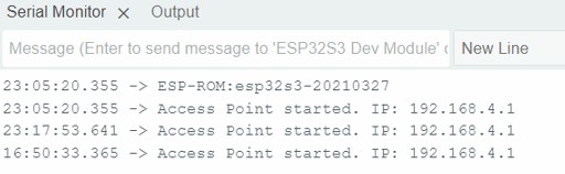
The code compiled and here is the serial port report:
ESP32 Client Code
Now I will burn code onto another ESP32 which will act as the client:
#include
#include

const char* ssid = "ESP32_S3_AP";
const char* password = "12345678";

#define BUTTON_PIN 1 // Push button input (active LOW)
bool lastButtonState = HIGH;
const char* serverIP = "192.168.4.1";

void setup() {
    Serial.begin(115200);
    pinMode(BUTTON_PIN, INPUT_PULLUP);

    WiFi.begin(ssid, password);
    Serial.print("Connecting to ");
    Serial.println(ssid);

    while (WiFi.status() != WL_CONNECTED) {
        delay(500);
        Serial.print(".");
    }

    Serial.println("\nConnected to AP. IP address: ");
    Serial.println(WiFi.localIP());
}

void loop() {
    bool buttonState = digitalRead(BUTTON_PIN);

    if (buttonState == LOW && lastButtonState == HIGH) {
        sendLEDCommand(true);
        delay(500); // Simple debounce
    } else if (buttonState == HIGH && lastButtonState == LOW) {
        sendLEDCommand(false);
        delay(500);
    }

    lastButtonState = buttonState;
}

void sendLEDCommand(bool turnOn) {
    if (WiFi.status() == WL_CONNECTED) {
        HTTPClient http;
        String url = String("http://") + serverIP + (turnOn ? "/on" : "/off");
        http.begin(url);
        int httpCode = http.GET();

        if (httpCode > 0) {
            Serial.printf("Sent %s, Response: %d\n", turnOn ? "ON" : "OFF", httpCode);
        } else {
            Serial.printf("Failed to send request: %s\n", http.errorToString(httpCode).c_str());
        }
        http.end();
    } else {
        Serial.println("WiFi not connected");
    }
}
Final Board Testing (05/24/25)
I have produced my final board chip and wanted to complete this assignment as I had done in class and privately using two Barduinos with ESP32 and creating a HTML app and an RGB controller to change the colour of an RGB through WIFI as well separately through LAN on the Barduino.
However, just before doing this assignment I realised that my voltage regulator which is taking in 5v and converting it to 3.3v to go into the ESP32 only could handle 100mA. However to use Wi-Fi may require around 250mA at least and it is recommended that I would have at least a voltage regulator with a capacity of 500mA. Otherwise, the Voltage regulator might burn out, or suffer from erratic behaviour, or just not work at all.
So after much searching on the internet I found out that there is a protocol called Bluetooth low energy (BLE), which would allow me to do simple actions like blinking and LED, switching on and off and altering the brightness. These actions might consume anywhere from 30mA of current to 80mA of current, and I might have to be careful about how brightly I switch on the LED as the current could spike higher than the maximum rating of the voltage regulator and then I would have a major problem.
BLE Web Interface Development
So, I asked ChatGPT to create code for a web-based LED control interface for an ESP32 MCU using Bluetooth Low Energy (BLE). I also stated that the app could use HTML, CSS, and JavaScript to create a webpage that connects to the ESP32 and sends it commands – but I emphasised that the code must be as simple as possible. It is important to make a point here that though the BLE code is web based, it is stored locally on my computer or on a mobile phone and not in HTML so it doesn't have that ability to be hosted on the ESP32. With wifi, it can be web based and hosted online or on the ESP32 itself.
Understanding UUIDs
- Service UUID (19b10000-e8f2-537e-4f6c-d104768a1214): Think of it as a folder on the ESP32 that holds related Bluetooth actions
- Characteristic UUID (19b10002-e8f2-537e-4f6c-d104768a1214): The specific item inside that folder that accepts commands:
- 0 = turn LED off
- 1 = turn LED on
- 2 = make LED blink
- 3-255 = set brightness level
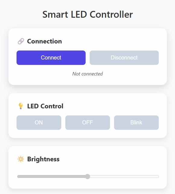
Web Control Panel Code
Arduino ESP32 Code
#include
#include
#include
#include

// UUIDs must match the web interface
#define SERVICE_UUID        "19b10000-e8f2-537e-4f6c-d104768a1214"
#define CHARACTERISTIC_UUID "19b10002-e8f2-537e-4f6c-d104768a1214"

const int ledPin = 21; // Built-in LED or change to your GPIO pin
const int pwmChannel = 0;
const int pwmFreq = 5000;
const int pwmResolution = 8;

bool isBlinking = false;
unsigned long lastBlinkTime = 0;
int blinkInterval = 500;
bool ledState = false;

class LEDCommandCallback : public BLECharacteristicCallbacks {
  void onWrite(BLECharacteristic* characteristic) override {
    std::string value = characteristic->getValue();
    if (value.length() > 0) {
      uint8_t command = value[0];

      if (command == 0) {
        isBlinking = false;
        ledcWrite(pwmChannel, 0);
        Serial.println("LED OFF");
      }
      else if (command == 1) {
        isBlinking = false;
        ledcWrite(pwmChannel, 255);
        Serial.println("LED ON");
      }
      else if (command == 2) {
        isBlinking = true;
        Serial.println("LED BLINKING");
      }
      else if (command >= 3 && command <= 255) {
        isBlinking = false;
        ledcWrite(pwmChannel, command);
        Serial.printf("LED Brightness: %d\n", command);
      }
    }
  }
};

void setup() {
  Serial.begin(115200);

  // PWM LED setup
  ledcSetup(pwmChannel, pwmFreq, pwmResolution);
  ledcAttachPin(ledPin, pwmChannel);
  ledcWrite(pwmChannel, 0);

  // BLE Setup
  BLEDevice::init("ESP32 LED Lamp");
  BLEServer* server = BLEDevice::createServer();
  BLEService* service = server->createService(SERVICE_UUID);
  BLECharacteristic* characteristic = service->createCharacteristic(
    CHARACTERISTIC_UUID,
    BLECharacteristic::PROPERTY_WRITE
  );

  characteristic->setCallbacks(new LEDCommandCallback());
  characteristic->addDescriptor(new BLE2902());

  service->start();
  server->getAdvertising()->start();

  Serial.println("BLE LED Controller is ready!");
}

void loop() {
  if (isBlinking) {
    unsigned long currentTime = millis();
    if (currentTime - lastBlinkTime > blinkInterval) {
      ledState = !ledState;
      ledcWrite(pwmChannel, ledState ? 255 : 0);
      lastBlinkTime = currentTime;
    }
  }
}
Testing with NRF Connect
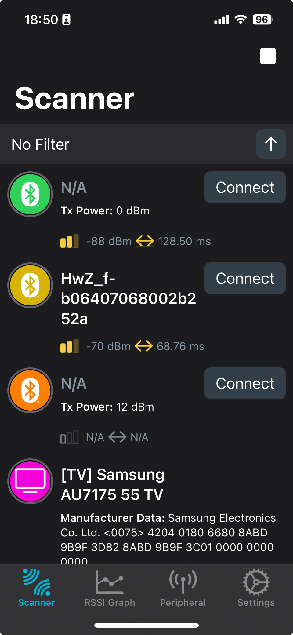
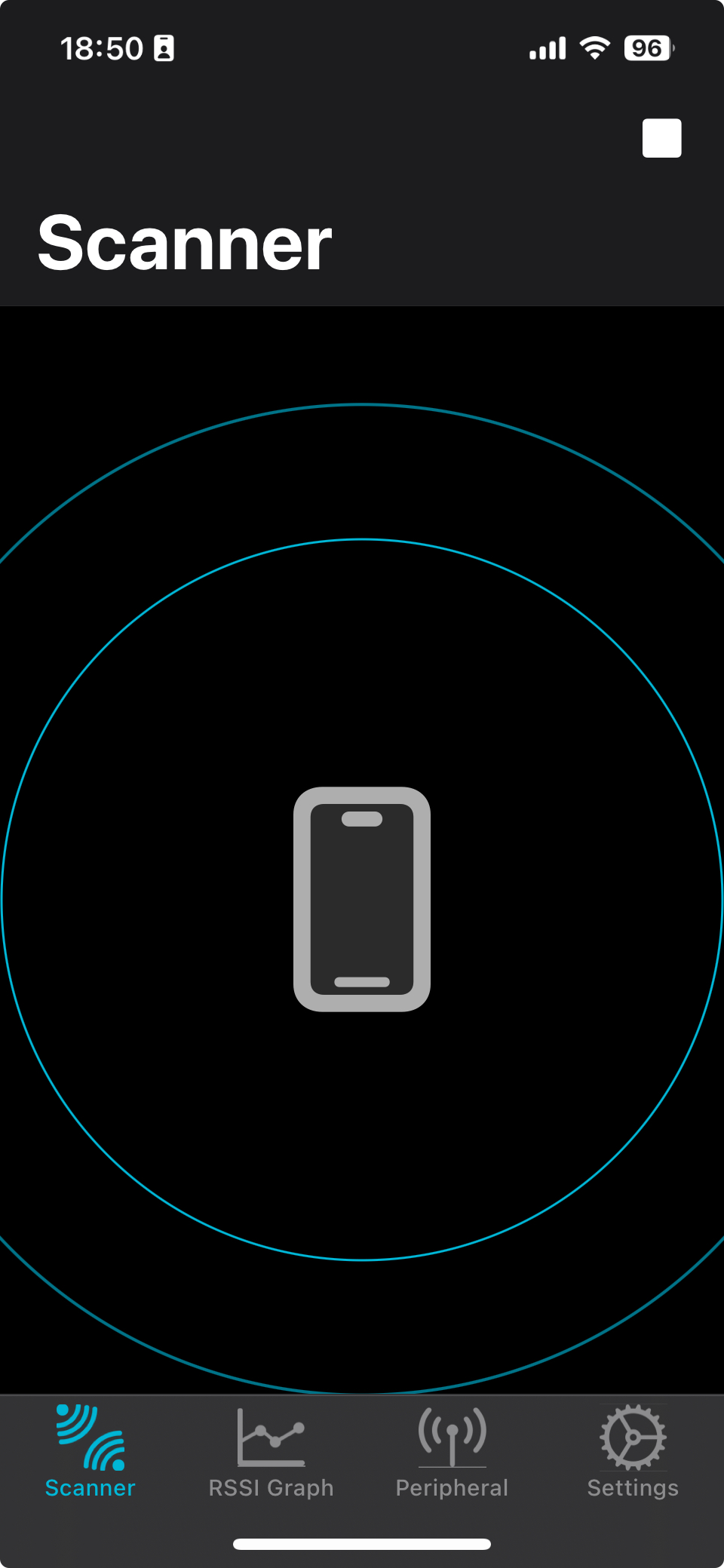
I downloaded NRF Connect which is a BLE scanner to test the connection:
So I clicked on PAIR and then was able to control a light on my development board to switch ON, OFF and to BLINK.
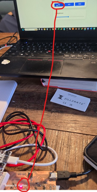
This photo shows the interface ON button being clicked and at the bottom of the picture the LED is ON.
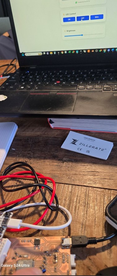
This photo shows the interface OFF button being clicked and at the bottom of the picture the LED is OFF.
This video shows the interface BLINK button has been pressed and at the bottom of the picture the LED BLINKS.
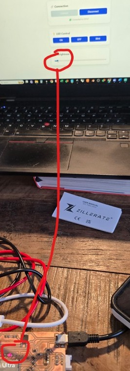
This photo shows the interface slider for brightness has been brought to the left side for minimum brightness and at the bottom of the picture the LED is ON but with very low brightness.
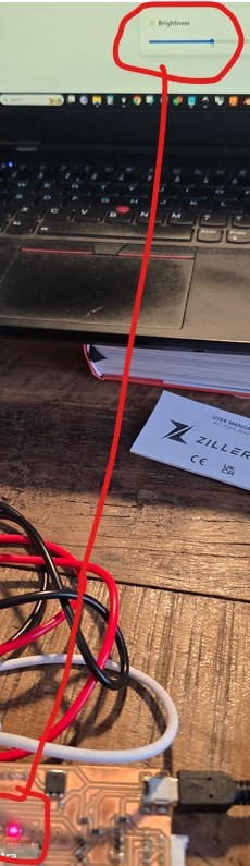
This photo shows the interface slider for brightness has been brought to the middle side for a reasonably bright LED and at the bottom of the picture the LED is ON quite bright and much brighter than before. I was concerned to switch it up to full brightness as i have been having power issues.
I was also able to alter the brightness. I have documented all this thankfully but it was not easy holding the jumper wire in position AND holding my phone to document AND pushing the buttons of the interface on the computer.
I was thinking that this is a wake up call for me to add a BOOT button to my device which would be very useful. Also I had mentioned to ChatGPT that sometimes I could see the ESP32 available for PAIRING on the network but then it would disappear again. I described my board and it had mentioned that larger capacitors may have worked and that I may not have needed jumper wires.
Since the BLE protocol means we have to store the code for webpage hosting the interface on a local computer or phone, I can save the interface file to my mobile phone and then operate it in the same way as I did here.
I will ask Dani about increasing capacitor size and putting in a BOOT button.
It seems like every time I try and do one little experiment I get thrown down a new rabbit hole. I mean that in a positive way, although getting to the last week or two of the course has me a little concerned that these teething troubles are still going on.