Week 15: System Integration
Assignment
Design and document the system integration for your final project
Smart Lamp System Integration Plan
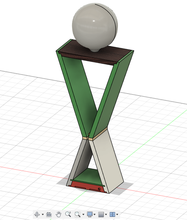
This plan outlines the steps, considerations and progress on integrating the electronic components and firmware into the physical structure of the smart lamp, which is to be manufactured using a combination of 3D printing (Bambu X1 Carbon) and CNC milling (SL 3200 Raptor). The lamp will provide automated lighting based on motion detection by a PIR sensor and offer manual control as well via a potentiometer for brightness and a three-position switch for mode selection (on-off-pir).
1. Design and Physical Structure
1.1. Manufacturing:
1.1.1. Component Design:
The first stage involves the detailed design of all parts of the lamp that will be manufactured using 3D printing (the diffuser and some of the intricate structural elements) and CNC milling (the base, main support ('legs') and upper structure ('arms and neck').
These designs must incorporate:
- 1.1.1.1. Precise internal dimensions and mounting features for all electronic components (ESP32 board, power supplies, PIR sensor, potentiometer, mode switch, LED strip).
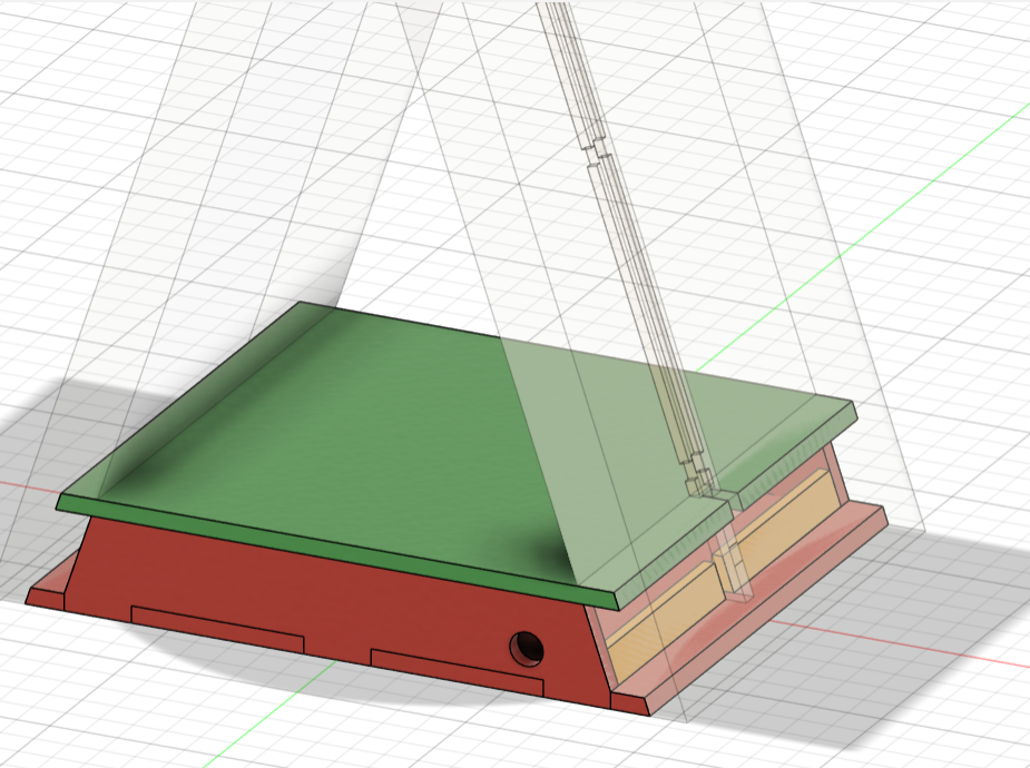
- 1.1.1.2. Dedicated and accessible pathways for wiring between different components, including a channel from the bulb opening at the top along one side of the underneath of the neck and then all the way down along the right side of the shoulder, to the leg and disappearing into the base where the chip and transformer are held.
- 1.1.1.3. Cutouts on the exterior of the base or support for the user interface elements (potentiometer and mode switch) and a centered cutout for the PIR sensor at the front.
- 1.1.1.4. An opening in the base at the back for the USB power cable (and potentially a separate port for a 24V power supply if used) as well as a cutout at the front right side for the PIR sensor.
- 1.1.1.5. Secure mounting mechanisms for the LED strip within the diffuser.
- 1.1.1.6. Consideration of small holes for heat dissipation if any components are expected to generate significant heat.
1.1.2. Material Selection:
PETG or PLA will be chosen for 3D printed parts based on factors like strength, temperature resistance, and ease of printing. The type of wood for CNC milling will be selected for its aesthetic properties and suitability for machining.
1.1.3. Manufacturing Process:
The designed parts will be fabricated using the Bambu X1 Carbon (3D printing) and the SL 3200 Raptor (CNC milling) according to the design specifications.
2. Electronic Component Integration
2.1. Component Placement:
2.1.1. ESP32 Board & Power Supplies:
These will be housed within the volume of the lamp's base, with separation between the microcontroller and a 30W 24V transformer to minimize interference. Secure mounting will be used (to be decided).
2.1.2. LED Strip:
This will be inserted and mounted within the underside of the top diffuser, ensuring even light distribution.
2.1.3. PIR Sensor:
This will be mounted at the front and centre right of the lamp through a designed hole. This should ensure an unobstructed field of view for motion detection.
2.1.4. Potentiometer & Mode Switch:
The potentiometer and mode switch will also be installed in cutouts on the exterior of the base, allowing for easy user access.
2.2. Wiring and Connections:
- 2.2.1. Wires will be routed through the internal grooves which lead from the central part of the neck at the top to the right side and all the way down into the base.
- 2.2.2. All internal wiring will be carefully managed to prevent tangling or strain.
- 2.2.3. Strain relief mechanisms (some kind of protective ring) will be implemented at the single rear exit point of the wires.
- 2.2.4. The USB power cable will connect to the ESP32 board within the base through a hole at the back. If a separate 24V supply is used for the LEDs, a separate connection point will be provided at the back, with internal wiring to the LED strip.
2.2. Base Housing:
The base will house all electronic components in a dedicated compartment, with a single exit point at the back for power cables.
2.3. Diffuser:
The diffuser will be 3D printed in white PLA with a specific pattern to create an interesting light effect.
3. Firmware Integration
3.1. Code Upload:
The pre-written firmware for the ESP32, developed using the Arduino IDE, will be uploaded to the microcontroller via the USB connection once components are connected to a working board.
3.2. Pin Configuration:
The firmware will be configured to correctly address the GPIO pins connected to the MOSFET (for LED control), the three-position switch (for mode selection), the potentiometer (for dimming), and the PIR sensor (for motion detection).
3.3. Control Logic Implementation:
3.3.1. Motion Detection:
The firmware will continuously monitor the PIR sensor input. Upon detecting motion at the "front" of the lamp, it will trigger the LED to turn ON. A timeout period will be implemented to turn the light OFF after a period of inactivity.
3.3.2. Brightness Control:
The firmware will read the analog input from the potentiometer and use Pulse Width Modulation (PWM) to control the brightness of the LED strip. This control will be active in all modes where the LED is ON.
3.3.3. Mode Selection:
The firmware will read the digital inputs from the three-position switch to determine the active mode:
- 3.3.3.1. ON Mode: The LED will remain ON at the brightness set by the potentiometer.
- 3.3.3.2. OFF Mode: The LED will remain OFF, overriding any motion detection.
- 3.3.3.3. PIR Mode: The automated activity-based lighting will be active, turning the LED ON upon motion and OFF after the timeout.
3.2. Base Assembly:
The base will be assembled from CNC milled pieces, incorporating the electronics housing and cable management system.


3.3. Electronics Integration:
4. Assembly Process
4.1. Component Installation:
Electronic components will be carefully installed in their designated locations within the 3D printed and CNC milled structure, ensuring secure mounting.
4.2. Wiring:
Internal wires will be routed through the designed pathways and connected to the appropriate pins on the ESP32 board, the LED strip, the potentiometer, and the mode switch. All wires will be directed towards the single rear exit point.
4.3. Mechanical Assembly:
The 3D printed and CNC milled parts will be joined together using the designed interlocking features or other fastening methods.
4.4. Final Connections:
External power cables (USB and potentially 24V) will be connected to the designated ports at the back of the lamp at the single exit point.
5. Testing and Refinement
5.1. Power-Up Test:
The lamp will be powered on to verify that all electronic components are functioning correctly.
5.2. Functional Testing:
Thorough testing of all modes (ON, OFF, PIR), brightness control via the potentiometer, and motion detection will be conducted. The timeout period in PIR mode will be verified.
5.3. Sensor Calibration (if needed):
The sensitivity and range of the PIR sensor might need minor adjustments in the firmware for optimal performance in the intended bedside table environment.
5.4. Feedback:
Gathering feedback on the lamp's functionality and usability will be important for any final refinements.
6. Final Integration
6.1. Cable Management:
Ensure the power cables at the single exit point at the back are neatly managed and pose no safety hazard.
6.2. Placement:
The smart lamp is ready for use.
This plan is still subject to change in certain areas (for example no housing have been created for components to sit in the base of the lamp or for the LED to be secured inside the diffuser).
This is however representative of the key aspects of integrating the hardware and software components into my custom-designed lamp structure and achieving desired automation.
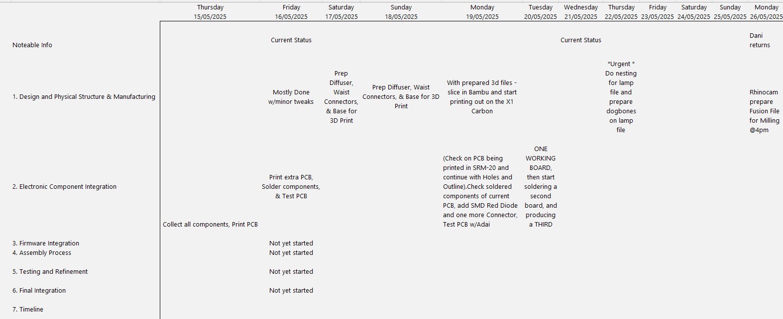
7. Timeline
Below are two screenshots of my daily activity time line for the system integration and documentation:

Images
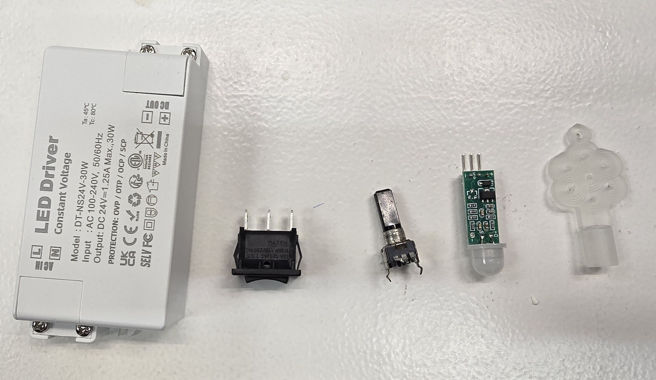
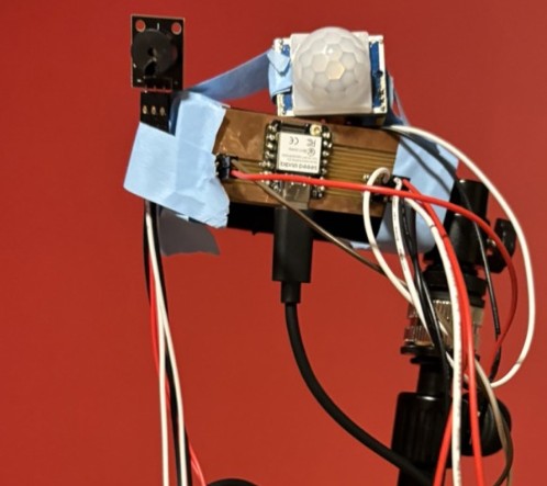
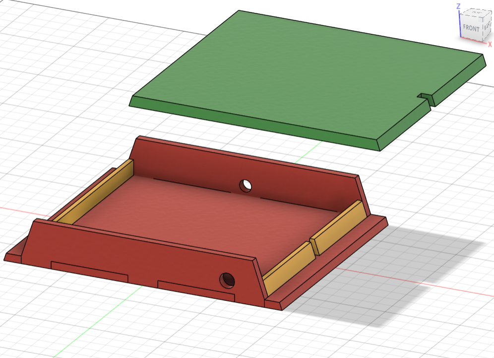
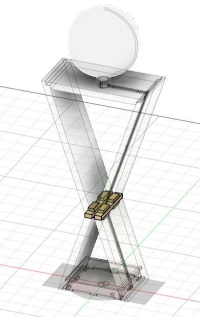
Lamp Deconstructed
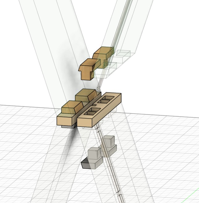
Components