Group Assignment
View our group assignment documentation
Individual Assignment
Week 06: Electronics Design
For week06, Electronic Design, we were first introduced to electricity and related concepts. There are so many layers as I understand it, and so one has to learn in layers if that makes sense.
As An extremely basic primer Dani gave us a concise electronics for geeks.
We learn from it that atoms have a nucleus with protons and neutrons inside, and that electrons move around an outer-shell. The strong nuclear force holds the nucleus together, while the electromagnetic force influences the movement of electrons.
Basic Terminology
What is voltage?
When we force electrons to group in a certain area, leaving another area without electrons, we create a difference in voltage. Electrons naturally want to move from a high-electron area (negative charge) to a low-electron area (positive charge) to restore balance. This movement of electrons is what we call electric current. Essentially, voltage creates an electric "pressure" that pushes electrons, and when a path is available (like a wire), they move, creating current.
What is current?
When two objects have a voltage difference between them, electrons naturally try to move to restore balance. This movement of electrons is called electric current. Current (measured in Amperes, A) tells us how many electrons are flowing through a material.
What is Ohm's Law?
When electrons move through a material due to voltage (V), they may find it easy or difficult to pass through. This difficulty is called resistance (R), measured in Ohms (Ω).
- If resistance is high, the flow of electrons (current) is small or even stops.
- If resistance is low, the current can be very large.
Ohm's Law, discovered by Georg Ohm, states that:
V (Voltage) = I (Current, Amperes (A)) ×R (Resistance, Ohms Ω)
Where resistance (R) is High Less current (I) flows and vice versa. If resistance is infinite (like an open switch), no current flows and If resistance is very low (like a wire touching itself), a huge current flows, creating a short circuit.
Electronic Design & Components
I will mention some components that we learnt about in electronic design relating them to my own project which is a lamp with PIR sensor that will switch on a lamp for a predetermined amount of time.
Resistors
A passive two terminal component that gives electrical resistance within a circuit. They reduce flow, adjust signal levels, divide voltages in order to protect components in a circuit.

(Source: FabLab BCN Documentation: https://fablabbcn-projects.gitlab.io/learning/educational-docs/fabacademy/classes/06-ElectronicsDesign/ )
Voltage Divider
A voltage divider is where two resistors are joined in a circuit, with the goal of turning a larger voltage into a smaller one. It can look like this.
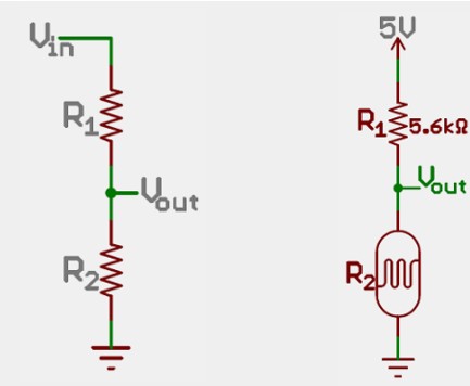
(Source: FabLab BCN Documentation: https://fablabbcn-projects.gitlab.io/learning/educational-docs/fabacademy/classes/06-ElectronicsDesign/ )
I initially thought I'd need to use a voltage divider instead of a voltage regulator or other methods because the PIR sensor output is a digital signal (HIGH = 5V, LOW = 0V), and we need to safely step it down to 3.3V so the SAMD11C microcontroller can read it without damage, but then I read the data sheet again and realised that I do not need one.
A voltage regulator is designed to power devices, not to adjust logic signals, making it slow and unnecessary for this purpose. A voltage divider, made from two resistors, proportionally reduces voltage by splitting the current between them, allowing us to precisely scale 5V down to 3.3V while maintaining the fast switching speed needed for digital signals.
Pull-up Resistor
This following is a pull up resistor. I have not yet included one in my diagram but I believe I will have to. The idea is that since we have digital circuits, the state of a pin i.e. on or off is floating. It could be either. And even if we think it is off, it might be that some rogue electric current bumps the pin into an on position. For this reason we use a pull up resistor which biases the pin to a particular state.
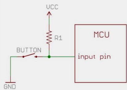
(Source: FabLab BCN Documentation: https://fablabbcn-projects.gitlab.io/learning/educational-docs/fabacademy/classes/06-ElectronicsDesign/ )
Resistor Color Coding
Here is a chart to help one understand resistor colour coding and values:
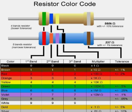
(Source: FabLab BCN Documentation: https://fablabbcn-projects.gitlab.io/learning/educational-docs/fabacademy/classes/06-ElectronicsDesign/ )
We take the values for the first 3 bands are and on the fourth band is the amount of zeroes on the end.
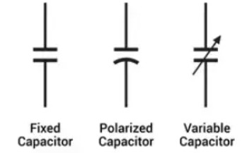
Capacitor
A capacitor is a device that stores electrical energy in an electrical field. It bumps up or absorbs extra electrical noise or when there is a shortfall for a moment. Many capacitors are called decoupling capacitors. Their job is to surpress high frequency noise in power supply signals. They take ripples in voltage which could be hardmful to a circuit and remove it from the voltage supply. They also can distribute energy into a circuit if needed.
(Source: FabLab BCN Documentation: https://fablabbcn-projects.gitlab.io/learning/educational-docs/fabacademy/classes/06-ElectronicsDesign/ )
Diode
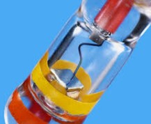
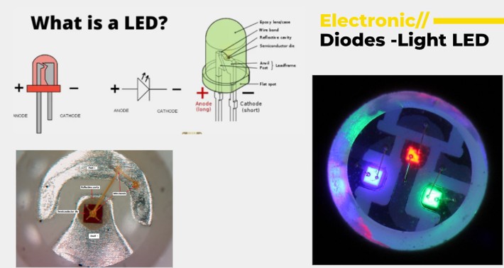
A diode is a two terminal electrical component that conducts current usually in one direction, with zero resistance in that direction and infinite resistance in the other.
(Source: FabLab BCN Documentation: https://fablabbcn-projects.gitlab.io/learning/educational-docs/fabacademy/classes/06-ElectronicsDesign/ )
(Source: FabLab BCN Documentation: https://fablabbcn-projects.gitlab.io/learning/educational-docs/fabacademy/classes/06-ElectronicsDesign/ )
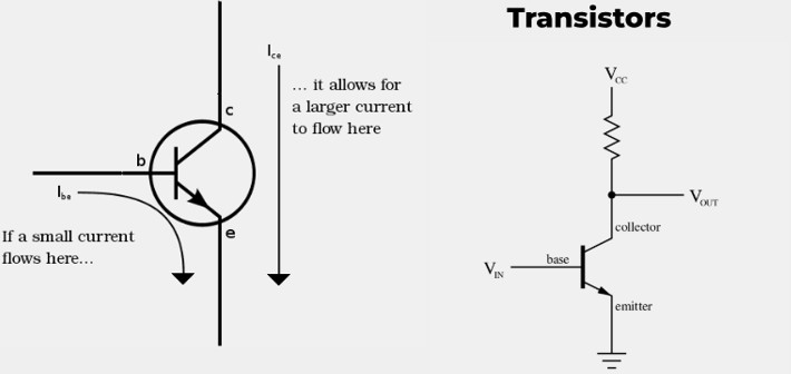
MOSFET
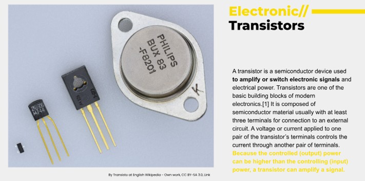
A Mosfet is used mainly for switching in electronics. It has 3 terminals:
- Gate which controls the conduction path
- Drain which is load facing
- Source which flows to the ground
(Source: FabLab BCN Documentation: https://fablabbcn-projects.gitlab.io/learning/educational-docs/fabacademy/classes/06-ElectronicsDesign/ )
(Source: FabLab BCN Documentation: https://fablabbcn-projects.gitlab.io/learning/educational-docs/fabacademy/classes/06-ElectronicsDesign/ )
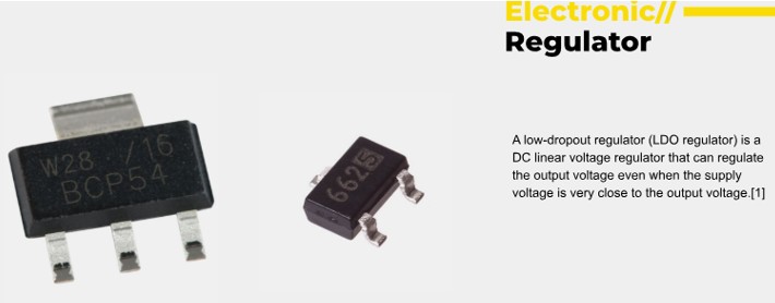
Voltage Regulator
(Source: FabLab BCN Documentation: https://fablabbcn-projects.gitlab.io/learning/educational-docs/fabacademy/classes/06-ElectronicsDesign/ )
A voltage regulator is useful for regulating the voltage in a circuit. For example if the voltage is coming in through the power supply at 5V and needs to be brought down to 3.3V to the MCU for safe operation so there is no MCU damage. It will also need capacitors nearby for extra protection to the circuit.
Importance of Datasheets
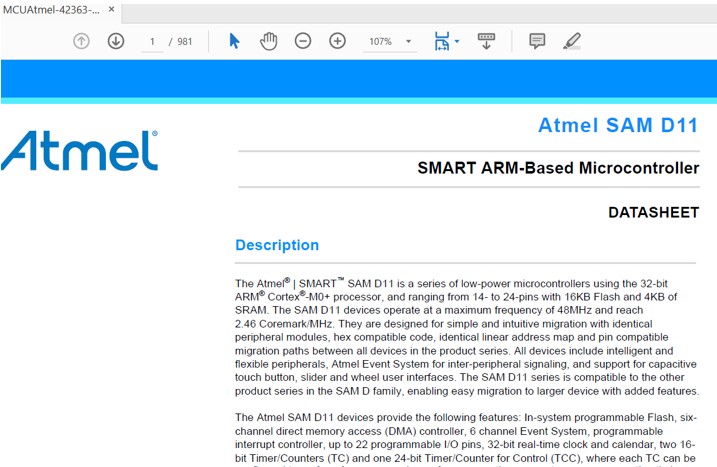
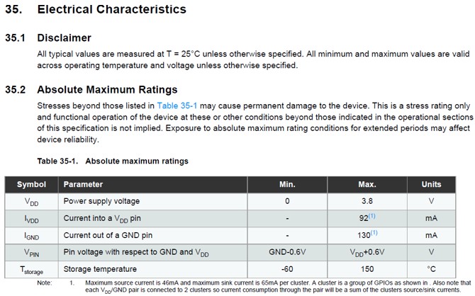
Next very important thing to have in your Electronic Design toolkit is to be aware of the Datasheets of each of the components. Daniel has really rammed home the importance of referring to these sheets. I consider it good practice to download the data sheets for each of my components as a first stop. Then, go through the description, features of the component, Electrical characteristics, and the pinout to see how the component operates and what it requires in terms of power or draws in terms of load on the overall circuit, operational limits. For example the SAMD11c sheet lets us know that we need to drop the voltage coming into the MCU to 3.3v. This is already well known to people who use this regularly but of course it cannot be intuited by someone new to this. Another example is that the datasheet gives us advice on what kind of capacitor should be added in close to the circuit, i.e. 4.7μF rather than 0.1μF.
CAD for Electrical Circuits
After perusing several datasheets we were introduced to CAD for Electrical circuits. A popular and free tool is called Kicad. (There are other such as Eagle, PCB.py, Fritzing). Now its about to get real. I have to admit that I was concentrating so hard and squeezing my braincells quite a bit up to this point that I lost concentration in the class room demonstration of drawing a circuit in kicad and I did not keep up. Also, the demonstration appeared to be a slightly involved arrangement.
The Rocky Road to becoming a board designer
In order to have a working product we go from concept, to design and then preparation. In Kicad we must select components that our final project requires and then draw a schematic. Once we have done that we can wire up the PCB design.
This is a screenshot of my schematic. For my final project, my MVP is a lamp which will switch on automatically after getting a signal from a PIR or similar device. I first listed all the components that I thought I would need for the circuit: An LED and pull up resistor, power supply connector with ground and D+ D-, a connector for a PIR sensor, a switch (MOSFET), voltage reducer and capacitors to stabilise power. I later found out that the LED that I thought was my main output would not be considered as such from a PCB design standpoint and I would have to add a connector for another light. I would also find out that I would have to connect a connector which is specific to the first boot and uploading of firmware. I have to accept at this stage that there is MUCH that I cannot know or intuit after 4 days studying electronics and PCB design. Getting a general idea, and familiarity with concepts and terminology is the initial goal.
So next we were introduced to Kicad. The A button is a shortcut to Placing new components. A search bar pops up and one searches for the required component such as a connector, LED, resistor or any other component. Some components might not be specified in a library, i.e. in my case the PIR sensor isn't specified in the library but we use a 3-pin header to represent it on the schematic.
So here is a draft of my schematic
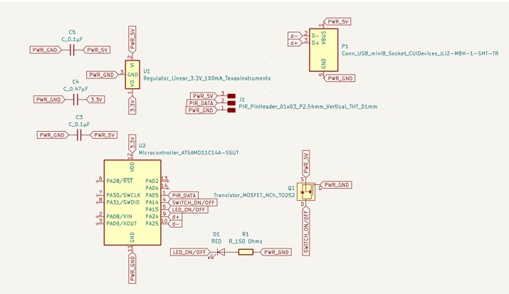
and since we now have the schematic we convert it to a PCB design by pressing

The PCB design window which is black will open up with all the components crushed together and we must organise them and then draw out all the traces, connecting PWR to PWR and GND to GND and other sockets to their relevant slots. This is how my draft looks after trying to arrange everything. I had a lot of help from Daniel Mateos in understanding this week, and it was much appreciated.
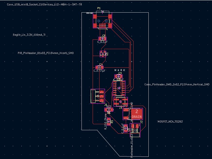
There will still be more to do in two weeks for the Production week. Meanwhile I will work on making this design more compact.
April Update - 04/17/25
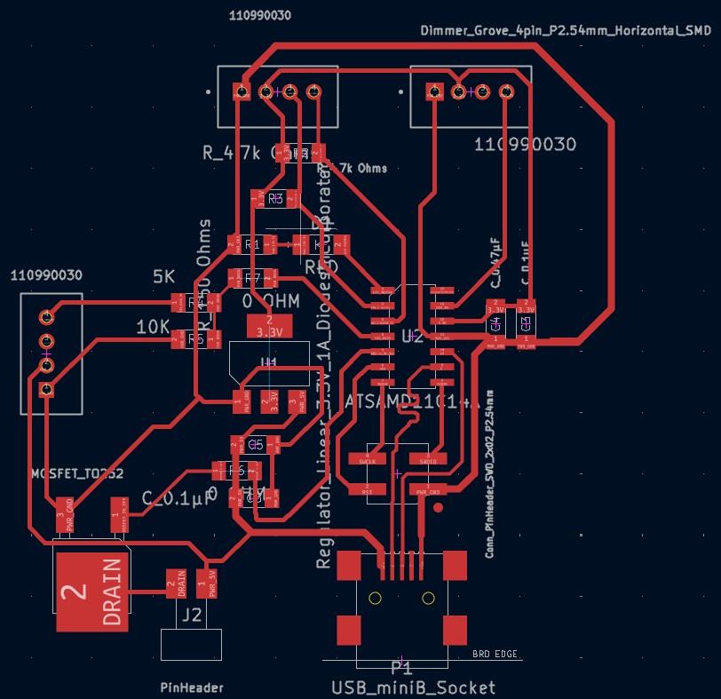
As of 17th April I have a current design and board
Here is the schematic
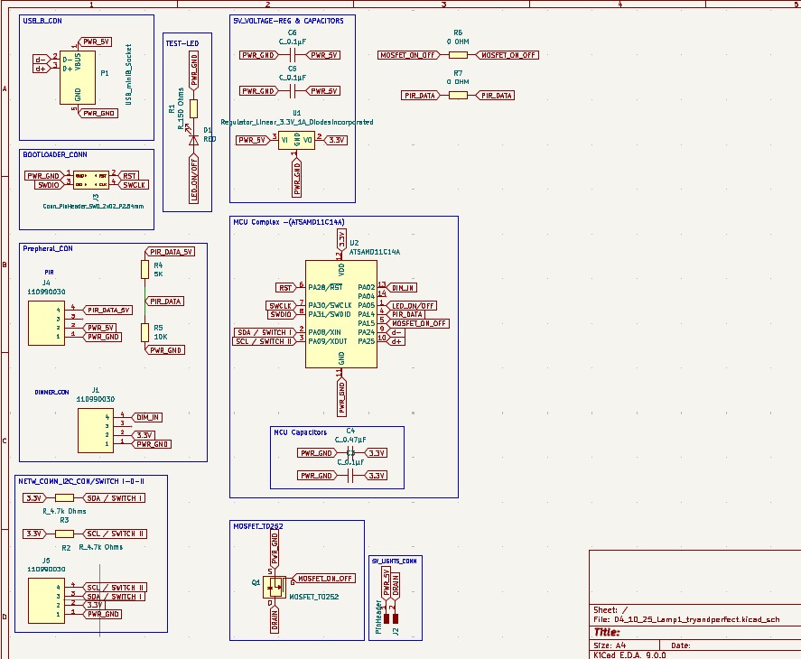
and the PCB design:
Reflections
When i started PCB Electronics design I thought it might be quite overwhelming. Now, like with most things on this course, I am sure of it! However, increasingly, with more practice, I catch glimpses of light slipping through the haze, quietly revealing a path to chase.
So, my understanding of PCB design is that we need to have some understanding of Electronics, touching aspects such as circuits in series, parallel, the concept of floating signals, pull-up and down resistors, capacitors, voltage reduction through voltage reducers or resistor based voltage division.
Next we need to understand where we are heading and then think about what components we will need to get there. We are introduced to the idea of reading data sheets to get information on the components we are using. Though they have a structure and one can find the information one needs, it is still very taxing to understand as there is a huge amount of technical language and at the start we may not know what to look for. One example might be checking how many volts a chip can handle coming into it (often 3.3V in the chips we deal with) and then understanding that in a 5v circuit there will be a need for a voltage reducer. Then one must understand how to know what voltage reducer to choose - but thats another story! Anyway, sometimes I go to sleep and hear Dani's voice saying, "Check the Datasheet!" You get the picture!
Next we need to understand principles of PCB design or PCB design rules, that when a circuit is actually constructed it really matters how it is built and what goes next to what. This is one of the many keys.
Initially it is suggested to keep data lines at not less than 0.2mm and preferably 0.3mm or even 0.4mm. Usually the power and ground lines can be made thicker than the others. Another basic rule is that 90 degree angles should be avoided with traces. When creating traces it is extremely likely initially that one will not be able to route all traces perfectly and will have to resort to 0 Ohm bridges to get to places that traces just can't go without crossing. Though it is elegant when designing a board to be able to find a way to route all traces this compensation becomes a necessity. It was fascinating watching Dani work out trace routes like a puzzle. That's yet another skill in Electronics design to master. Dani resisted my constant whispers of "Let's use autoroute, what about the autoroute!". The force is strong in this one! Also, to be honest, doing it oneself is a big learning experiencing...and the autorouting software I used didn't work very well.
Different rules are revealed as one has new experiences. For example, it is important to have capacitors before and after the MCU to protect it from surges, and this translates to the need for physical proximity on the board. Or another example is making sure that data channels (D+ D-) are drawn at similar widths, and there is a very precise accepted tolerance which design software helps calculate. I had various experiences where I learnt these things.
Once, the board is built we must solder it, test it, and then in some cases go back to the drawing board and redesign, or resolder. Issues could be hardware, the design or indeed in the production.
I created my board with a SAMD11c, it has honestly been a big pain for me as there is a potential component not working on it.
This weekend though i was able to make two Fablab chips (Barduino ESP32-S3) communicate as part of another weeks work, I couldn't make the ESP32 chip talk to this SAMD11c or vice versa! I spent many hours on this and will be creating a new similar board with an ESP32, so i have more space, more perfection and hopefully a board that works perfectly.
Addendum: I also wanted to add that we first learn to create the PCB schematic so we know where everything is to be connected, and then the PCB design where we must consider the physical traces.
In the PCB schematic stage I found a very good youtube channel called PCB Cupid.
This helped me to make my schematics very clean and clear and well labelled.