
Week 12: Mechanical Design & Machine Design
Assignment
- Group Assignment:
- Design a machine that includes mechanism + actuation + automation + application
- Build the mechanical parts and operate it manually
- Document the group project
- Individual Assignment:
- Document your individual contribution
The group assignment page is here.
Individual Assignment
Project Ideation
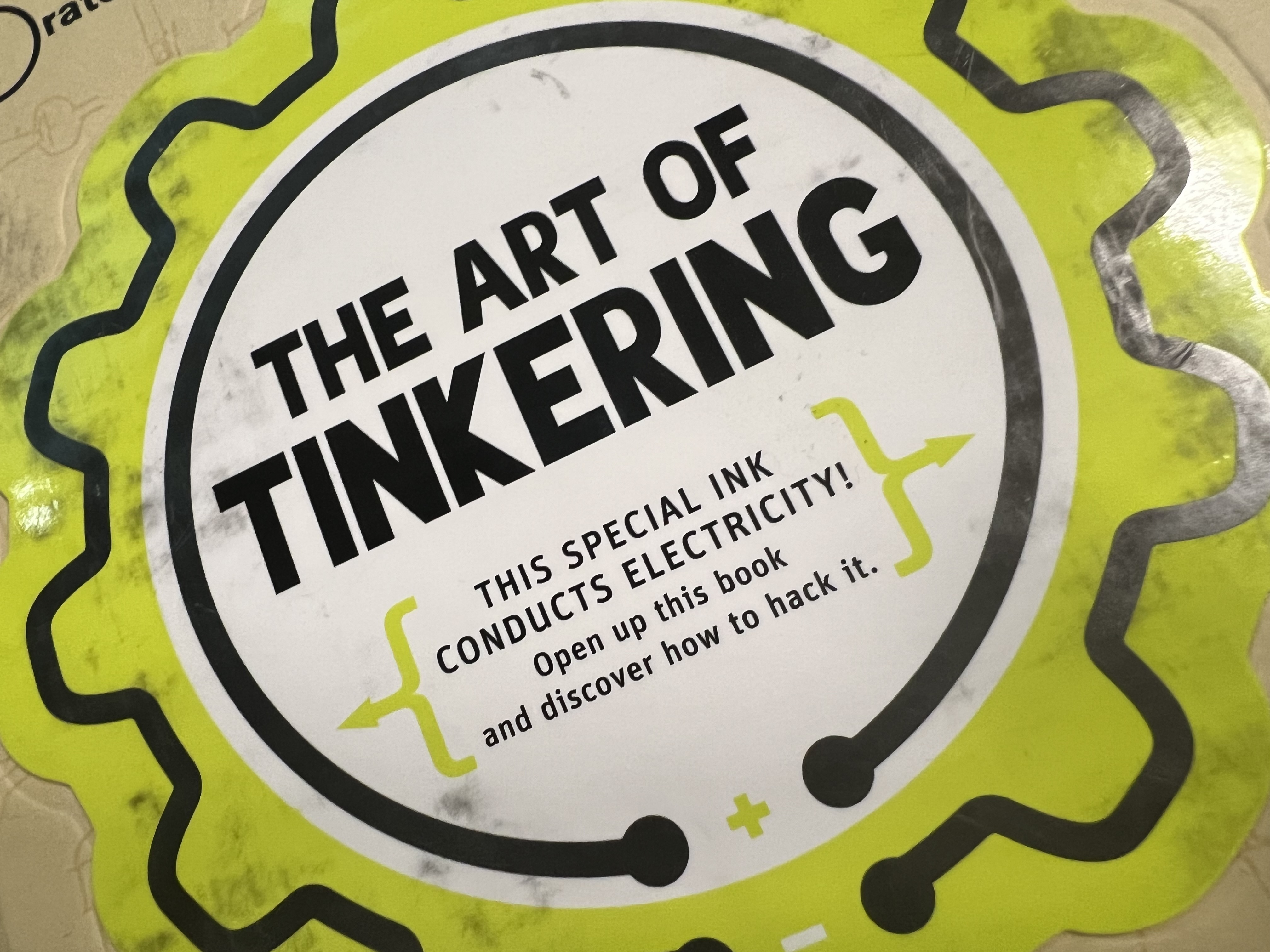
One Friday some books arrived that Danny had ordered. Dani, Andrew and I were flipping through and the idea of a wire bender looked very cool to all of us.
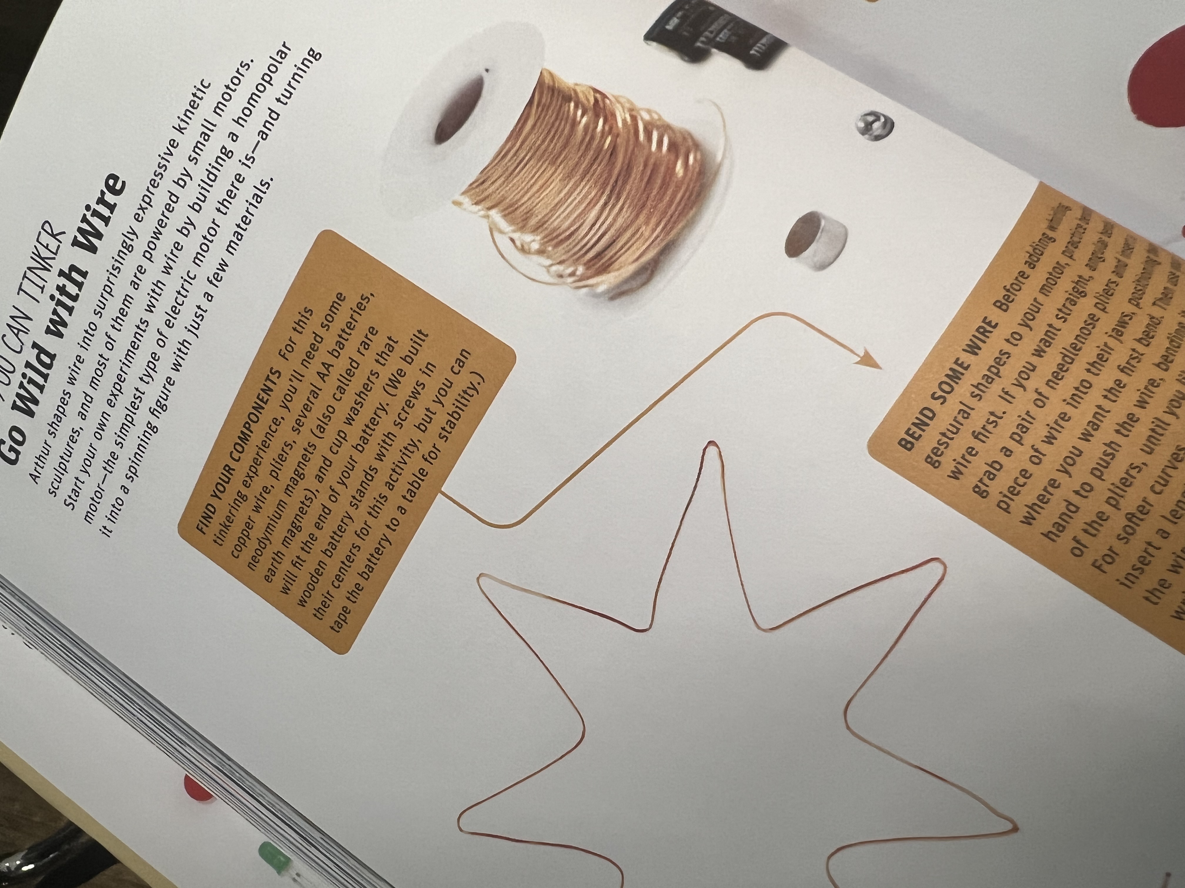
The following Monday each member posted several ideas each and we voted in two rounds. Eventually the Wire-bender won, but there were many interesting ideas, such as a blimp and a submarine and several others.
We settled on the CNC Wire-bender with the idea of being able to create small wire sculptures on demand. A final version might be able to take a photo of something, or describe it and then select a shape or pattern with the help of an API interface with ChatGPT, then the Wire-bender would autonomously create the sculpture.
We found a decent looking Wirebender project online with plenty of documentation, here, and Gonzalo had the idea to re-create it as a first spiral and then to move on to improving, adding new parts and so forth. This would minimise our development time and allow us to have a working machine and could spend more time on improvements.
First Stage - The Initial Prototype
I took the files and started printing out the pieces as they were as well as giving some internal measurements to Andrew who wanted to make some improvements and adjustments to the pieces which would make them sturdier for the second stage.
I spent quite a while taking measurements and partially creating a BoM. At this stage we were just trying to see what pieces we had, what they did and how it would all fit together.
During this process Andrew also eliminated a number of parts which were redundant. By this point we had read over reviews discussing that the Wirebender was badly designed, and that the feeder and straightener did not work effectively.
Second Stage – Overhaul
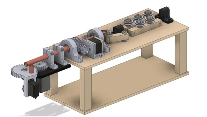
As a group we decided to overhaul the feeder and the straightener. The original CAD looked like this:
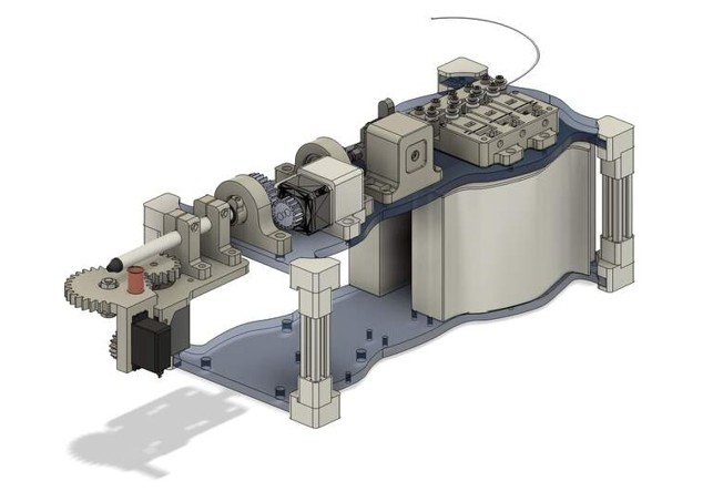
Our group revised CAD which Andrew took the lead on looked like this:
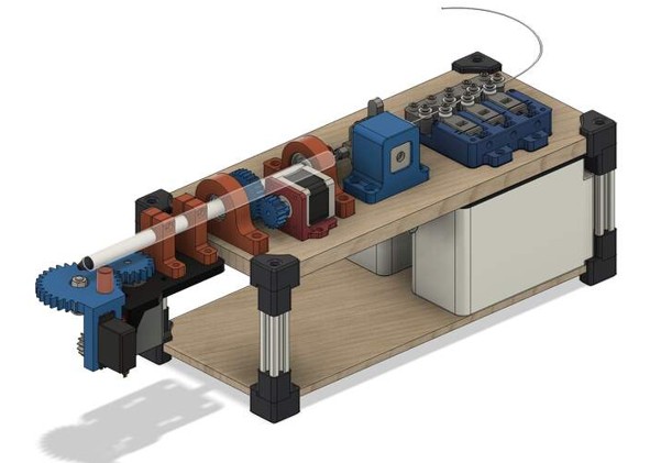
Firstly, all of the design was done in PLA as this would be more accurate and durable than using plywood. The number of wheels in the feeder assembly were increased and made smaller with the idea of making the feeding more accurate, and the number of straighteners were increased.
The Wirebender was mounted in such a way that speed was preferred over precision with the idea that the precision would be taken care of at a later moment. They key issue was making sure that the wire could feed straight through the machine. It was not essential for all the components to be perfectly accurate. Another issue which cropped up was the finger/tail shaped component with screw that is supposed to tighten the wire as it is fed into the copper tube and that wasn't wholly satisfactory.
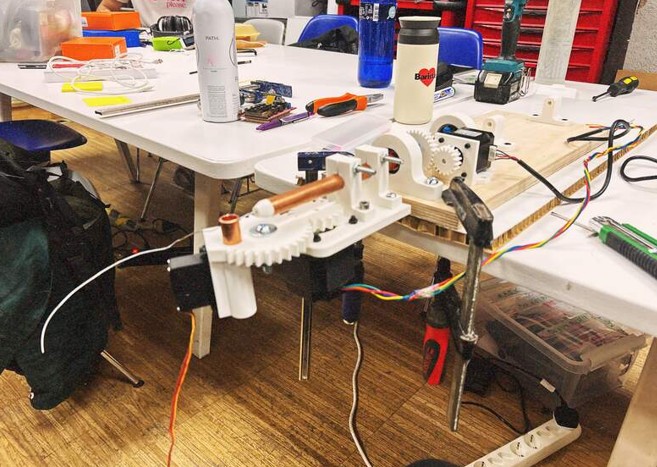
A first version was assembled and clamped to the table.
The original design had been tightened up and improved in terms of the fitting of components and also some filleting and chamfering for the aesthetics.
Third Version
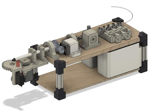
Andrew made a final change to the prototype where the focus was on the feeder being able to feed the wire in to the tube more tightly, and the actual copper tube itself was swapped for a slimmer aluminium one.
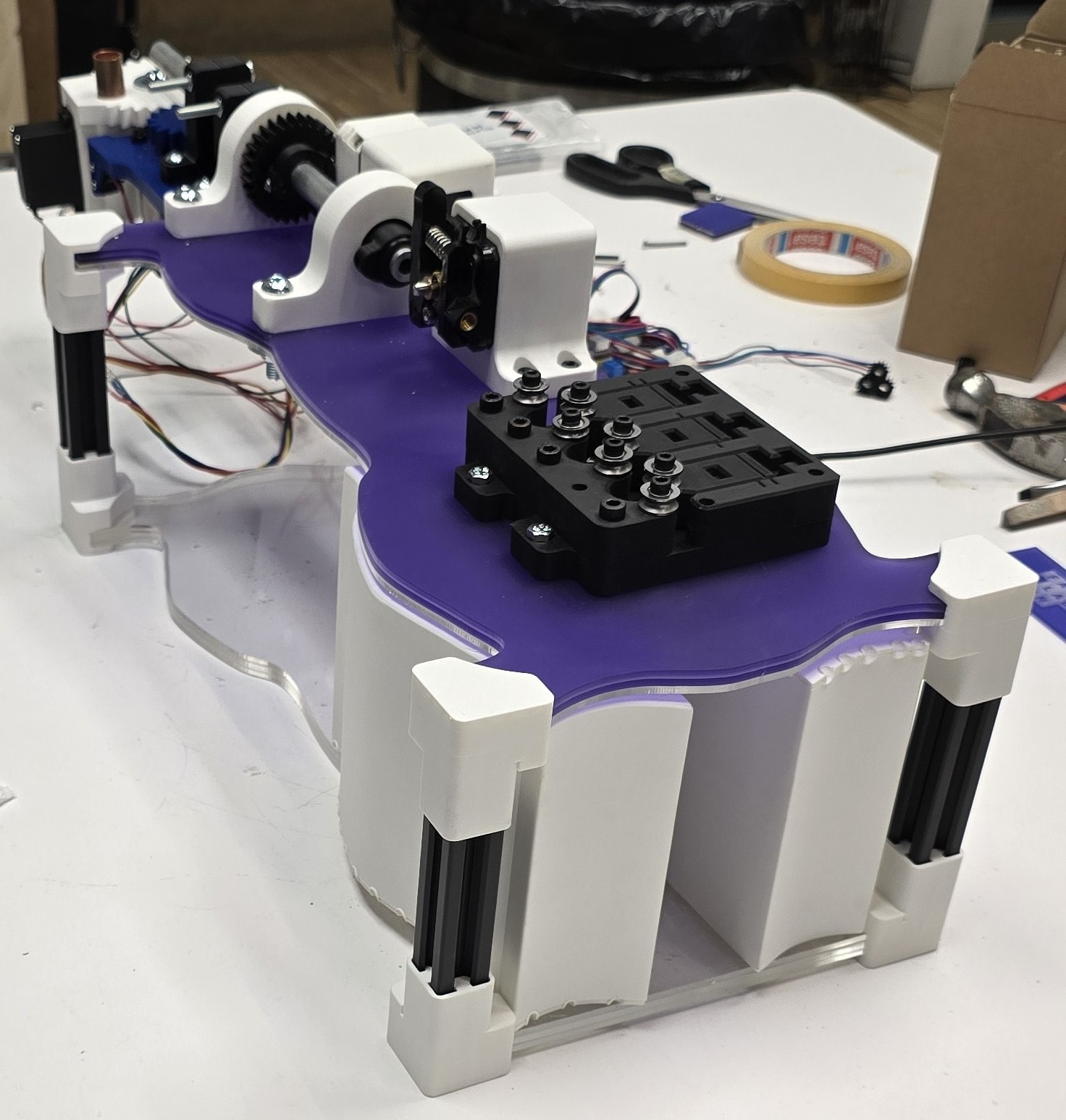
Also, since there was a heavy NEMA 17 stepper gear right at the front, and the machine was very much front-heavy the group added gravel bins at the back to balance the machine and prevent it pitching forward. A key consideration for the bins was strength since it would be filled with gravel, so more wall loops for the 3-D printing were in order.
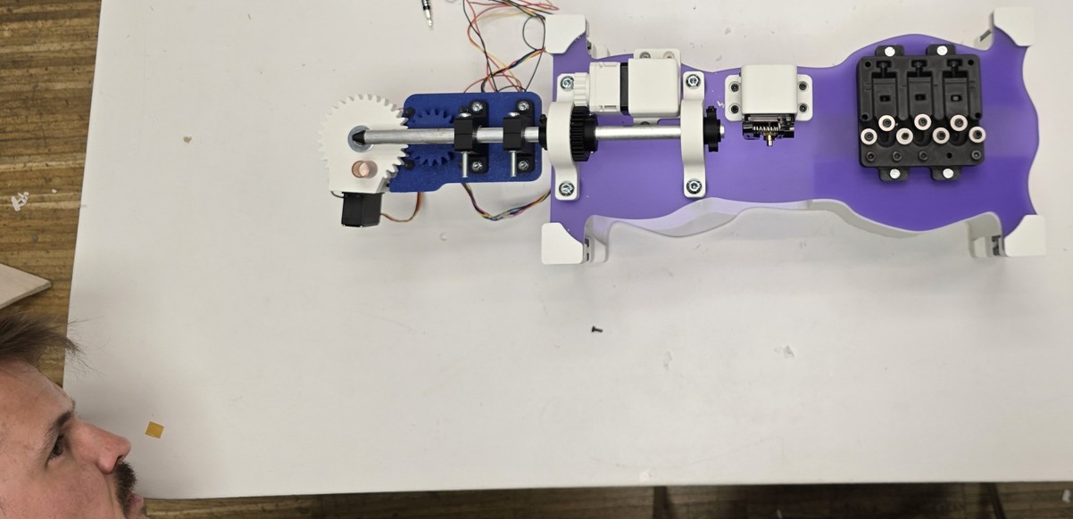
Final Version – Aesthetics and Spool Design
In the last stage were talking more about the aesthetics and had ideas about the Wirebender looking like a ray gun. Camilla our talented aesthetist came up with some very cool designs and 3D printed them as well as helped us to source some purple and transparent acrylic.
I had been looking at some professional Wirebenders and noticed that really it was quite similar to the design we had except that the professional version seemed to have more of a spool. I offered to design a spool and stabiliser to git on the back and make the feeding of the wire into the pipe smoother and did so. Sadly, these final version adjustments barely made it to the final cut as we were racing to finish up to 10mins before the Global call started. We were in the end very happy with the effort we had made eventhough we would now say we could have done way way better.
Ed spent most of the time on the stepper motor, and connecting it up, and Gonzalo came up with an awesome app that he created using Unity software – with this mobile phone app Gonzalo was able to issue commands to the stepper motor to turn on the X, Y, and Z axis as desired. It was really impressive.
Final Assembly
Cutting of the acrylic was done by Ed and I – we had a heck of a lot of trouble prepping the file in Rhino for some reason. We came in fresh the next morning and Ed got it printed. Luckily all the sizes were correct.
The final assembly was enjoyable and smooth. Andrew and I took videos and pictures, searched for screws and bolts and rebuilt the whole machine with care.
We were extra cautious so as not to crack the acrylic which was looking pretty and had to do some on the fly cuts of acrylic and attaching it to stabilise some wobble which was noticed around the end of the aluminium pipe.
Review and Improvements
To think at the start we had even considered doing two projects.
It would be great to see the machine working again robustly and go for some additional changes.
Since we were in a rush, there was more focus on speed and less time for thoughtful, qualitative adjustments. Andrew, who works as a builder, took a lead in the group—he pushed timelines, drove improvements, and made quick decisions on the spot. I made suggestions along the way, and he was great to work with—there was no ego, and he was always open to input, even though he had the most experience in the group.
I would have liked the opportunity to sit down and reimagine what a Wirebender could be, without being influenced by existing designs. It struck me as a device that feels somewhat prone to failure—though that may not be entirely accurate, it was simply a personal impression I had.
I've often found myself drawn to that kind of thinking—questioning assumptions, exploring alternatives, and considering how something could be approached in a completely new way. It's a mindset I've carried into my previous work experiences, and one that I genuinely enjoy.
Our Baby
Assembly Process
Future Improvements
Personally, if there was a little more time. I'd like to see an enclosure built to make it less prone to being damaged at the same time as helping it to look more badass!
I was very irritated by the feeding mechanism and would really like to ponder different ideas for improving that. Surprisingly as a I mentioned previously, this design was not a million miles away from big industrial wire benders. The fact that engineers have had years to investigate this made me wonder whether I was off base completely, however, why not! The final aspect that this Wirebender could really benefit from was more automation rather than it being such a manual process and calling out X, Y and Z co-ordinates. I think all that would keep a team very busy!