
Week 10: Output Devices
Assignment
Group Assignment
Measure the power consumption of an output device
Individual Assignment
Add an output device to a microcontroller board you've designed, and program it to do something
Group Assignment
Our Group Assignment can be found here
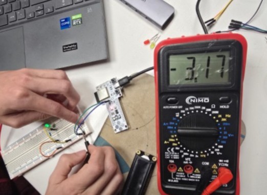
Our goal is to measure the power consumption of an output device. As an example, we used a Barduino microcontroller on a breadboard, connected to a resistor and an LCD 1602 display. We compiled and uploaded code to confirm the LCD was working correctly—a message successfully appeared on the screen.
Voltage Measurement (using a parallel method):
The circuit was built in a series configuration, meaning the components (resistor, LCD, etc.) were connected one after the other in a single path:
3.3V (VCC) to resistor to LCD to GND
To measure voltage, however, we must connect the multimeter in parallel to the component we're measuring. This is because voltage represents the difference in electrical potential between two points.
We set the multimeter to DC Voltage (V) and left the circuit fully connected.
- The red probe was placed on the LCD's anode (still connected to the resistor).
- The black probe was placed on the LCD's cathode (connected to GND).
With a green LED, we measured a voltage drop of approximately 2.0V across it.
To measure the supply voltage (VCC), we placed the red probe on the 3.3V pin of the Barduino and the black probe on GND, reading a value of 3.17V.
This demonstrates how a multimeter reads the "electrical pressure" between two points—i.e., voltage.
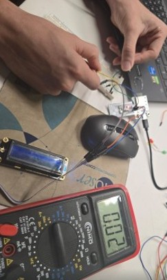
Current Measurement (using a series method):
To measure current, we must place the multimeter in series with the component we're measuring. That means we need to temporarily break the circuit and insert the multimeter so that all current flows through it.
We set the multimeter to DC Current (A or mA) and moved the red probe to the correct port for current (either 10A or mA, depending on expected flow).
To measure the current flowing through the LCD:
- We disconnected the wire between the resistor and the LCD's anode.
- Then we connected the red probe to the resistor output (where the LCD's anode was connected) and the black probe directly to the LCD's anode.
The current now flowed like this:
VCC → resistor → multimeter → LCD to GND
With the multimeter now part of the circuit, it was able to measure the full current flowing through the LCD.
We expected around 15–20 mA, and our reading confirmed this: 20 mA.
Power Calculation (P = V × I):
To calculate power consumption:
Power (Watts) = Current (Amps) × Voltage (Volts)
0.02 A × 3.17 V = 0.0634 Watts
So, the LED circuit is consuming approximately 63 milliwatts.
Reflections on the Group Assignment:
I did the group assignment with Gonzalo and actually it was a big eye opener for me as I learned four main things:
- Voltage must be measured in parallel with the component being used, because it represents the difference in electrical potential between two points. For example, to measure the voltage across the LCD, we left the circuit connected and placed the probes on either side of the LCD.
- Current must be measured in series, meaning the multimeter becomes part of the circuit. We had to break the circuit temporarily and insert the multimeter so that the current would flow through it, which helped us measure how much current the LCD was drawing.
- I also understood how to configure the multimeter properly, such as switching the red probe port and selecting the right measurement mode (voltage vs. current), which is important for getting accurate readings and avoiding damaging the multimeter.
- Finally, that coming back to this Weeks documentation a month later I realised that though it was familiar, it was already slightly hazy in my memory - and how important these notes are - once we have additional insights its great to come back to them and refresh the notes.
Individual Assignment
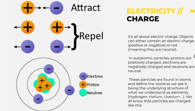
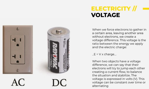
Defining and understanding terms
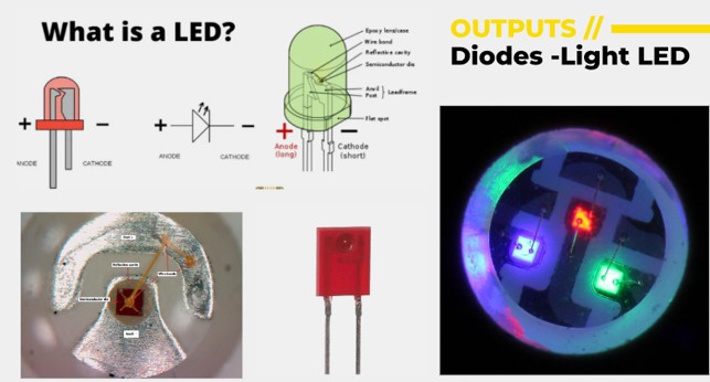
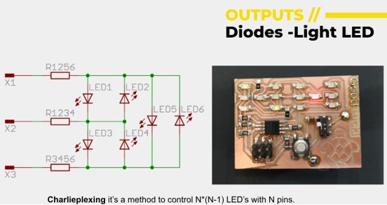
To understand output devices, it helps to look at them in three main categories: visual, audio, and physical. Each type delivers information from a system to the user in a different way.
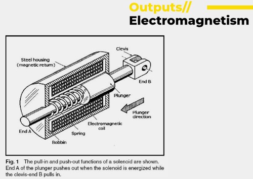
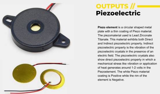
Visual output devices can be LCD screens, LED screens, Projectors, Printers. Audio output devices like speakers or headphones produce sound or music and physical output devices generate movement or tactile feedback – these can be motors, or haptics, solenoids (linear motion), heaters or pumps to name a few.
(Source: FabLab BCN Documentation: https://fablabbcn-projects.gitlab.io/learning/educational-docs/fabacademy/classes/10-OutputDevices/ )
(Source: FabLab BCN Documentation: https://fablabbcn-projects.gitlab.io/learning/educational-docs/fabacademy/classes/10-OutputDevices/ )
(Source: FabLab BCN Documentation: https://fablabbcn-projects.gitlab.io/learning/educational-docs/fabacademy/classes/10-OutputDevices/ )
(Source: FabLab BCN Documentation: https://fablabbcn-projects.gitlab.io/learning/educational-docs/fabacademy/classes/10-OutputDevices/ )
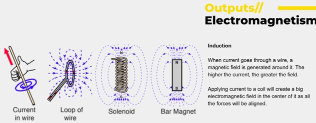
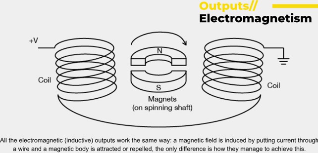
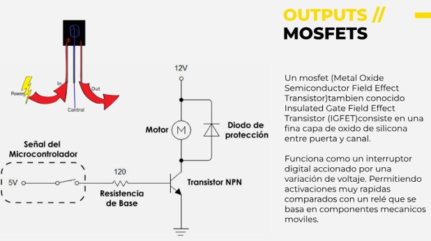
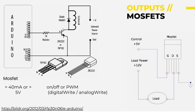
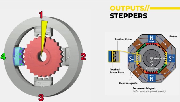
Output devices can be controlled electronically to convert power into motion, light, sound and other useful things.
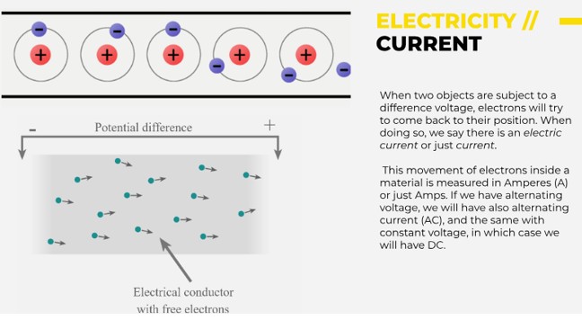
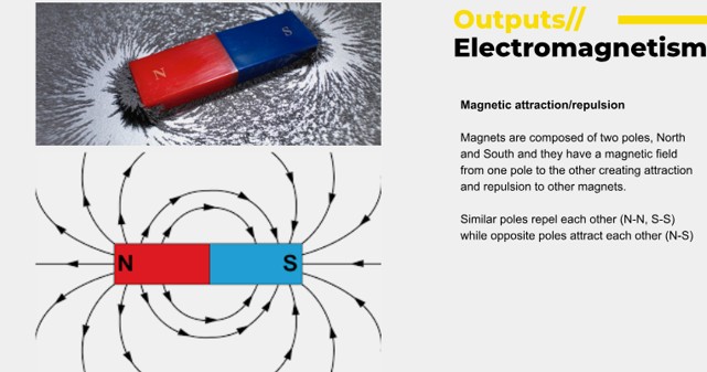
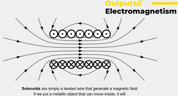
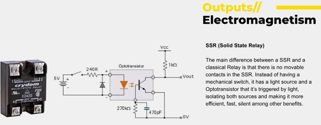
There are more concepts that we need to understand such as Electromagnetism.
(Source: FabLab BCN Documentation: https://fablabbcn-projects.gitlab.io/learning/educational-docs/fabacademy/classes/10-OutputDevices/ )
(Source: FabLab BCN Documentation: https://fablabbcn-projects.gitlab.io/learning/educational-docs/fabacademy/classes/10-OutputDevices/ )
(Source: FabLab BCN Documentation: https://fablabbcn-projects.gitlab.io/learning/educational-docs/fabacademy/classes/10-OutputDevices/ )
(Source: FabLab BCN Documentation: https://fablabbcn-projects.gitlab.io/learning/educational-docs/fabacademy/classes/10-OutputDevices/ )
(Source: FabLab BCN Documentation: https://fablabbcn-projects.gitlab.io/learning/educational-docs/fabacademy/classes/10-OutputDevices/ )
(Source: FabLab BCN Documentation: https://fablabbcn-projects.gitlab.io/learning/educational-docs/fabacademy/classes/10-OutputDevices/ )
(Source: FabLab BCN Documentation: https://fablabbcn-projects.gitlab.io/learning/educational-docs/fabacademy/classes/10-OutputDevices/ )
(Source: FabLab BCN Documentation: https://fablabbcn-projects.gitlab.io/learning/educational-docs/fabacademy/classes/10-OutputDevices/ )
(Source: FabLab BCN Documentation: https://fablabbcn-projects.gitlab.io/learning/educational-docs/fabacademy/classes/10-OutputDevices/ )
(Source: FabLab BCN Documentation: https://fablabbcn-projects.gitlab.io/learning/educational-docs/fabacademy/classes/10-OutputDevices/ )
(Source: FabLab BCN Documentation: https://fablabbcn-projects.gitlab.io/learning/educational-docs/fabacademy/classes/10-OutputDevices/ )
(Source: FabLab BCN Documentation: https://fablabbcn-projects.gitlab.io/learning/educational-docs/fabacademy/classes/10-OutputDevices/ )
(Source: FabLab BCN Documentation: https://fablabbcn-projects.gitlab.io/learning/educational-docs/fabacademy/classes/10-OutputDevices/ )
(Source: FabLab BCN Documentation: https://fablabbcn-projects.gitlab.io/learning/educational-docs/fabacademy/classes/10-OutputDevices/ )
(Source: FabLab BCN Documentation: https://fablabbcn-projects.gitlab.io/learning/educational-docs/fabacademy/classes/10-OutputDevices/ )
(Source: FabLab BCN Documentation: https://fablabbcn-projects.gitlab.io/learning/educational-docs/fabacademy/classes/10-OutputDevices/ )
(Source: FabLab BCN Documentation: https://fablabbcn-projects.gitlab.io/learning/educational-docs/fabacademy/classes/10-OutputDevices/ )
(Source: FabLab BCN Documentation: https://fablabbcn-projects.gitlab.io/learning/educational-docs/fabacademy/classes/10-OutputDevices/ )
(Source: FabLab BCN Documentation: https://fablabbcn-projects.gitlab.io/learning/educational-docs/fabacademy/classes/10-OutputDevices/ )
(Source: FabLab BCN Documentation: https://fablabbcn-projects.gitlab.io/learning/educational-docs/fabacademy/classes/10-OutputDevices/ )
(Source: FabLab BCN Documentation: https://fablabbcn-projects.gitlab.io/learning/educational-docs/fabacademy/classes/10-OutputDevices/ )
(Source: FabLab BCN Documentation: https://fablabbcn-projects.gitlab.io/learning/educational-docs/fabacademy/classes/10-OutputDevices/ )
(Source: FabLab BCN Documentation: https://fablabbcn-projects.gitlab.io/learning/educational-docs/fabacademy/classes/10-OutputDevices/ )
(Source: FabLab BCN Documentation: https://fablabbcn-projects.gitlab.io/learning/educational-docs/fabacademy/classes/10-OutputDevices/ )
Datasheets
Remember to match the specifications to the requirements of what we are building.
(Source: FabLab BCN Documentation: https://fablabbcn-projects.gitlab.io/learning/educational-docs/fabacademy/classes/10-OutputDevices/ )
03/27/25 - Some Random Nuggets
1 WATT (James Watt) = like a bright flashlight
Examples: magimix 1300 watts, hairdryer 1000wats, one has to be aware of wattage and the effect on the current
Some Formulas
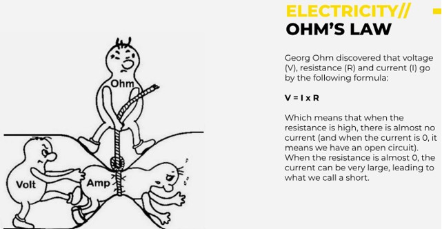
Power = voltage x intensity (current)
(and v=I.R)
24 watts = 12volts . 2A(amps)
In a 5v circuit, led drops 3v then resistor must drop 2, so we need 100 ohm resistor so that would be r=v/1 = 2/0.02 = 100 ohms
The relationship between volts, amps, and watts is that watts (power) are calculated by multiplying volts (voltage) by amps (current): Watts = Volts x Amps.
Here's a more detailed explanation:
- Volts (V):
Measure the electrical potential or "push" that drives the flow of electricity. Think of it as the water pressure in a pipe. - Amps (A):
Measure the amount of electrical current, or the flow of electricity, through a circuit. Think of it as the volume of water flowing through a pipe. - Watts (W):
Measure the rate at which electrical energy is used or the amount of power. It's the product of volts and amps.
Here's a simple analogy:
- Volts: Like the pressure of water in a hose.
- Amps: Like the amount of water flowing through the hose.
- Watts: Like the total power of the water flow, which is determined by both the pressure and the amount of water.
Week 10 Practical
We had to take a breadboard or our chip and connect it up to different Output devices then load a program into Arduino to make it do different things. I wrote the following code to move a motor back and forth.
But I have came across an error
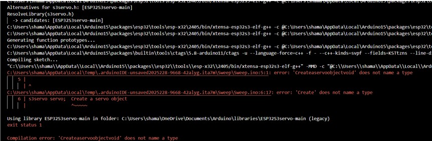
Ok so I learned quite a bit here after Dani came to the rescue….it seemed that the servo library itself needed to pull or call a function from the board support package. I was using Arduino's latest version and certain things in it were not supported as they had previously been….so I needed to go back a version. Once I went to the previous board support package version, the code compiled and worked immediately.
Also, one has to remember to check that they are connected to the correct board, on the correct USB port and that USB CDC is enabled on boot.
But, after all this nothing worked. So with Dani's help we tested a few different servo motors and found that it was the servo that was broken. When we first learn programming there is a lot of self doubt, but as part of the debugging we must also go through the process of checking everything including the components.
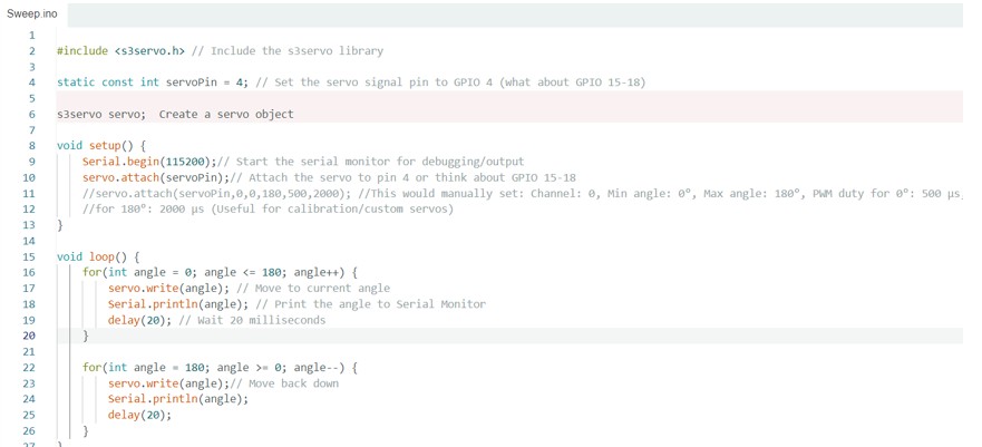
#include // Include the s3servo library
static const int servoPin = 15; // Set the servo signal pin to GPIO 15
s3servo servo; //Create a servo object
void setup() {
Serial.begin(115200);// Start the serial monitor for debugging/output
servo.attach(servoPin);// Attach the servo to pin 4 or think about GPIO 15-18
//servo.attach(servoPin,0,0,180,500,2000); //This would manually set: Channel: 0, Min angle: 0°, Max angle: 180°, PWM duty for 0°: 500 µs, PWM duty
//for 180°: 2000 µs (Useful for calibration/custom servos)
}
void loop() {
for(int angle = 0; angle <= 180; angle++) {
servo.write(angle); // Move to current angle
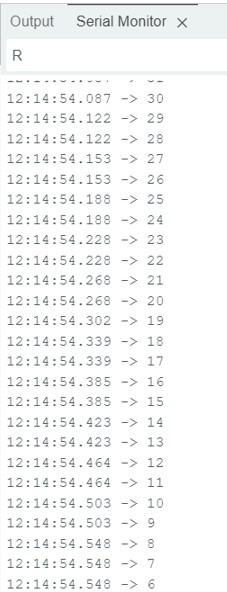
Serial.println(angle); // Print the angle to Serial Monitor
delay(20); // Wait 20 milliseconds
}
for(int angle = 180; angle >= 0; angle--) {
servo.write(angle);// Move back down
Serial.println(angle);
delay(20);
}
} And here the serial monitor shows the program instructing the motor to run through angles
So I connected the SG90 servo again and was glad it was finally working.
This mp4 shows the code running through angles 1 – 180 and back and one can see the motor moving.
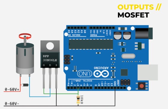
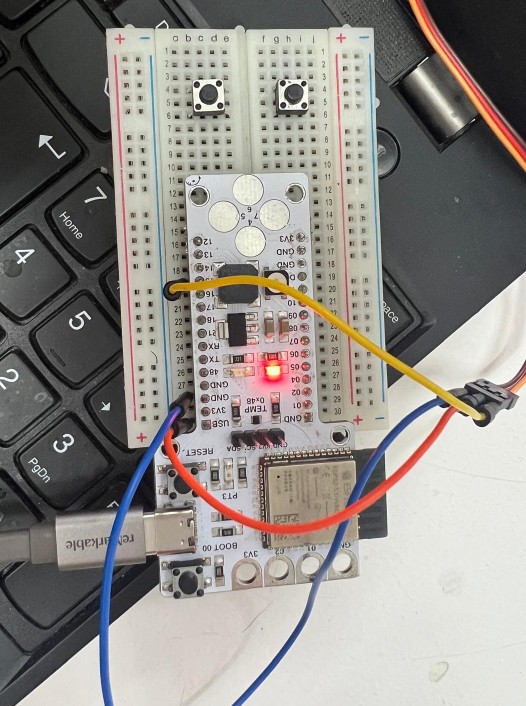
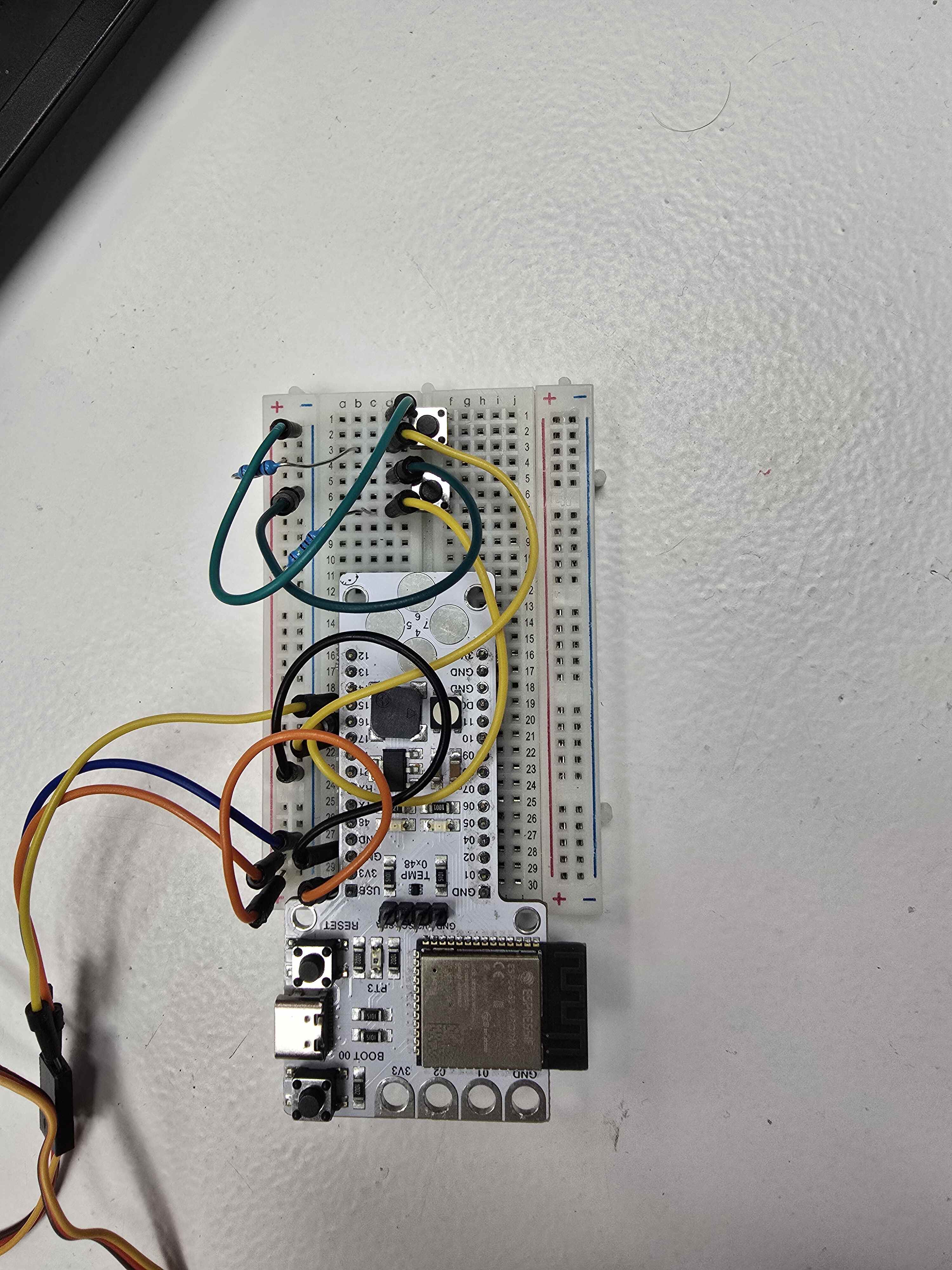
I think it's worth taking a moment to go through the Arduino wiring too.
Week 10 Practical Monday Morning
The lesson was a big mess for me on Thursday and Friday and that stuck with me over the weekend. One has to remember to check wiring, code logic, that one is using the correct library and that it doesn't conflict with the version of Arduino. One must also check components to see that nothing is burned out and that there is a signal going through the system. Sadly, in my experience as a great proponent of AI, chatgpt, Deepseek and all AI I tried were useless and I was very grateful for Dani who helped immensely.
Since it is Monday morning - I will attempt a few different experiments again and hope that I can get some results to document.
I start with what was done on Friday and am glad to say everything worked fine:
Then I tried a slightly different code adding in delays to slow down the way the motor moves and that worked fine so I am moving on.
#include

static const int servoPin = 15;
s3servo servo;
int currentPosition = 0;  // Keep track of where the servo is

void setup() {
    Serial.begin(115200);
    servo.attach(servoPin);
    servo.write(0);  // Start at 0 degrees
    delay(1000);     // Give it time to reach starting position
}

void loop() {
    // Forward movement
    for(int target = 0; target <= 90; target += 15) {
        // Move one degree at a time to the target
        while(currentPosition < target) {
            currentPosition++;
            servo.write(currentPosition);
            delay(500);  // Small delay between degree changes
        }
        Serial.print("Reached Position: ");
        Serial.println(currentPosition);
        delay(1000);  // Pause at the target position
    }

    // Backward movement
    for(int target = 75; target >= 0; target -= 15) {
        // Move one degree at a time to the target
        while(currentPosition > target) {
            currentPosition--;
            servo.write(currentPosition);
            delay(500);  // Small delay between degree changes
        }
        Serial.print("Reached Position: ");
        Serial.println(currentPosition);
        delay(1000);  // Pause at the target position
    }
}
LCD Display Implementation
Then I was curious to see if I could make a LCD return some text as I may use one in a future project. I got hold of a DF Robot LCD1602 RGB Backlight Module v1.0.
I looked online and found that the library I wanted is called DFRobot_RGBLCD1602 library. I searched for it and downloaded it from the Arduino Libraries. This library facilitates communication with the display via the I2C protocol and allows control over both the text and the RGB backlight. I went to Sketch > Include Library > Manage Libraries and searched for DFRobot_RGBLCD1602 and clicked install.
I connected the pins as can be seen in the following photo
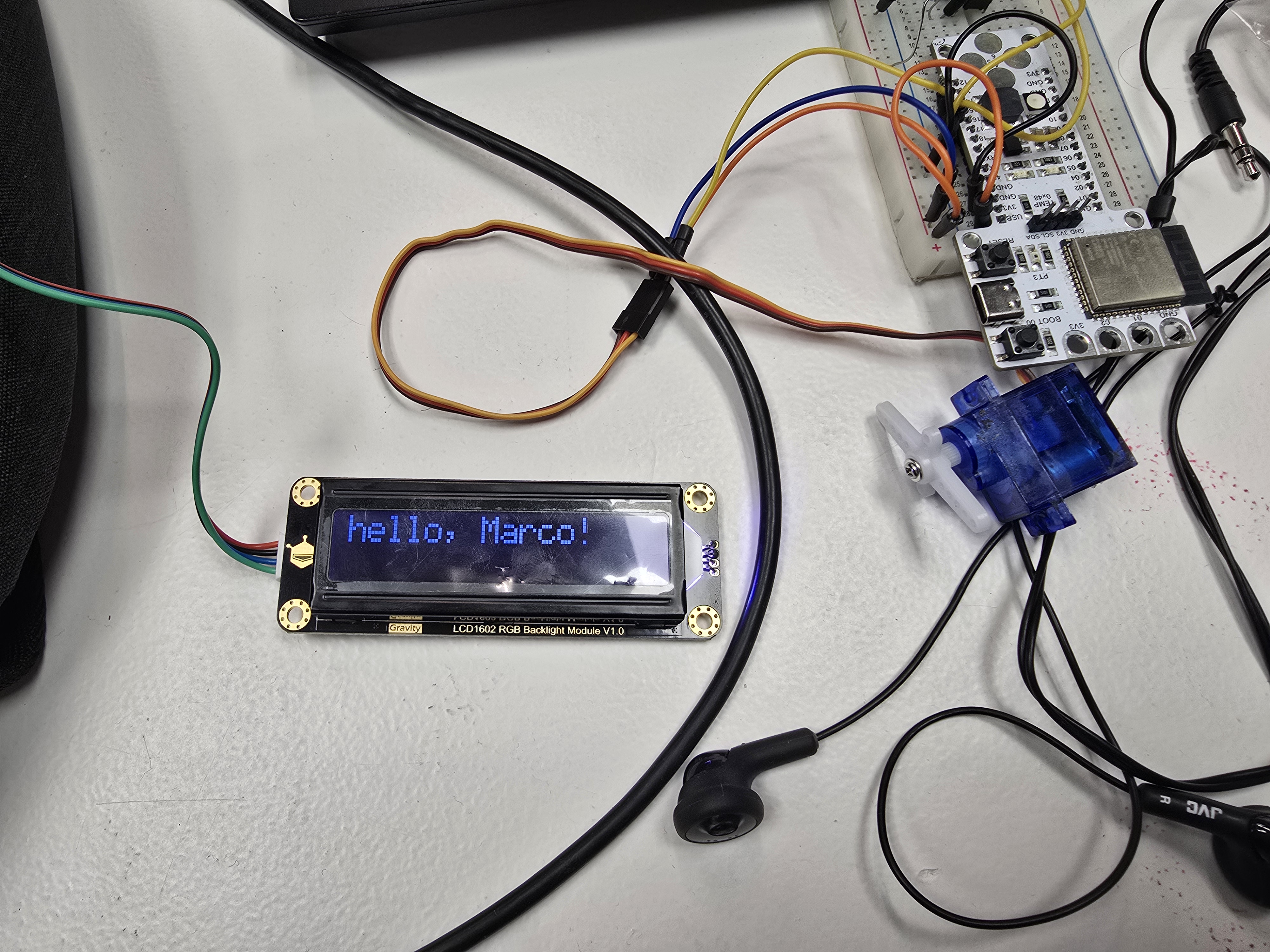
Then I connected the LCD1602 module pins
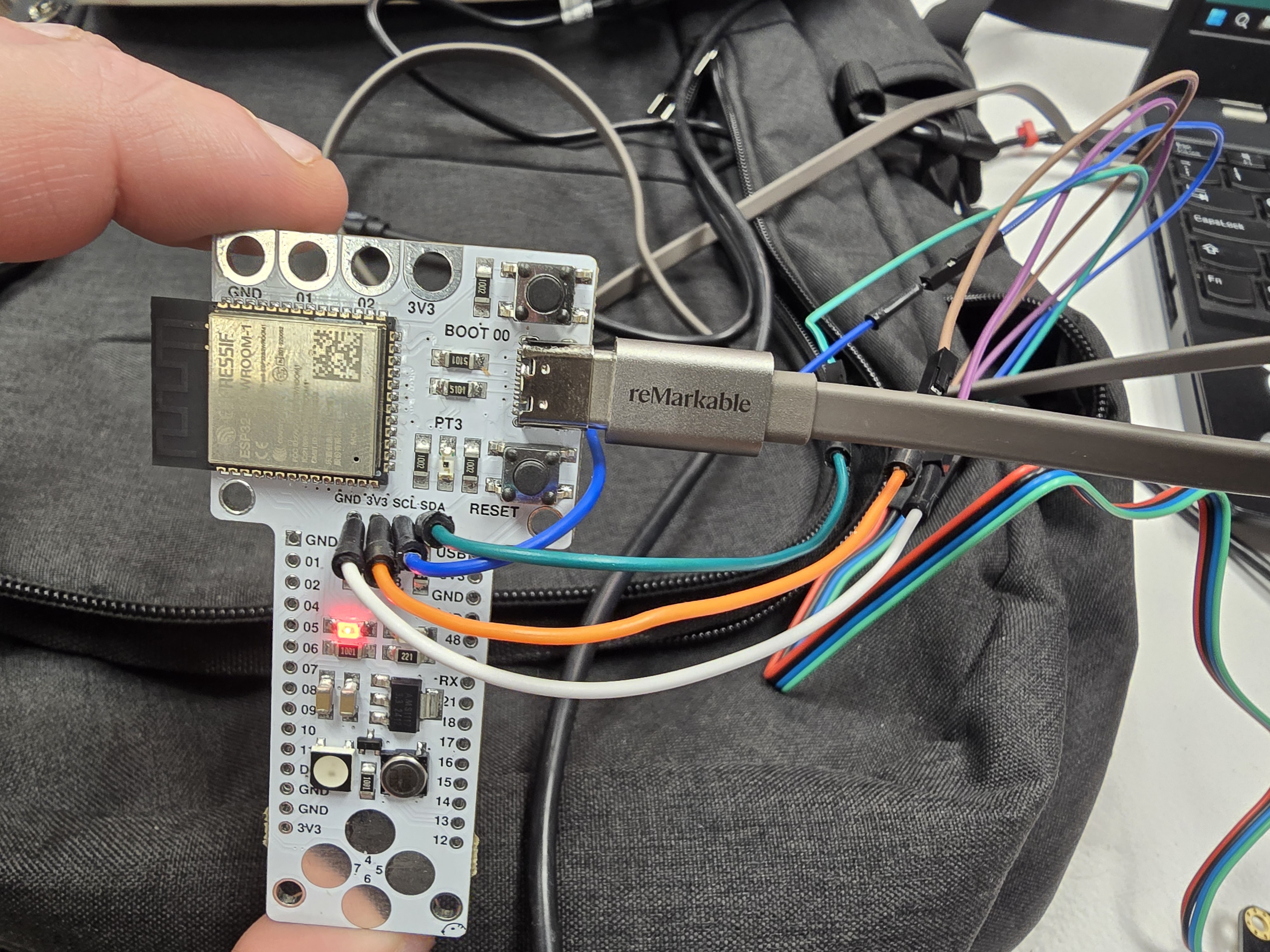
The lcd uses the I2C interface, and requires four connections:
- VCC: Connect to the 5V pin on the Arduino.
- GND: Connect to the GND pin on the Arduino.
- SDA: Connect to the SDA pin (A4 on Arduino Uno).
- SCL: Connect to the SCL pin (A5 on Arduino Uno).
Apparently the display has and I2C address for the LCD (LCD Address: 0x3E ) and also for the RGB backlight control (RGB Backlight Address: 0x60). The addresses are predefined in the library, but can be changed manually in GitHub
I decided to go through a few of the provided code examples. The first one just flashes my name:
/*!
 * @file Display.ino
 * @brief display.
 * @copyright Copyright (c) 2010 DFRobot Co.Ltd (http://www.dfrobot.com)
 * @licence     The MIT License (MIT)
 * @maintainer [yangfeng](feng.yang@dfrobot.com)
 * @version  V1.0
 * @date  2021-09-24
 * @url https://github.com/DFRobot/DFRobot_RGBLCD1602
 */
#include "DFRobot_RGBLCD1602.h"

/*
Change the RGBaddr value based on the hardware version
-----------------------------------------
       Moudule        | Version| RGBAddr|
-----------------------------------------
  LCD1602 Module      |  V1.0  | 0x60   |
-----------------------------------------
  LCD1602 Module      |  V1.1  | 0x6B   |
-----------------------------------------
  LCD1602 RGB Module  |  V1.0  | 0x60   |
-----------------------------------------
  LCD1602 RGB Module  |  V2.0  | 0x2D   |
-----------------------------------------
*/

DFRobot_RGBLCD1602 lcd(/*RGBAddr*/0x60 ,/*lcdCols*/16,/*lcdRows*/2);  //16 characters and 2 lines of show

void setup() {
    /**
     *  @brief initialize the LCD and master IIC
     */
    lcd.init();
    // Print a message to the LCD.
    lcd.print("hello, Marco!");
}

void loop() {
    /**
     *  @brief Turn off the display off
     */
    lcd.noDisplay();
    delay(500);

    /**
     *  @brief Turn on the display
     */
    lcd.display();
    delay(500);
}
Update 05/02/25 - Success Controlling an Output Device with my Development Board (SAMD11c)
This board was able to control an output device (BLUE LED) with the newly milled SAMD11C with the potentiometer/dimmer as the input device.
Unfortunately it seems this board had issues which are undiagnosed and so I am redesigning my board and going to use an ESP32 which will have more pins, and Bluetooth and wifi capability.
Final Reflections
This week was negatively affected by issues with my development board and when i finally got it working it technically passed by achieving the goal of actuating an output device. However, I was personally dissapointed as I didn't know what was wrong with my board and could not remedy the issue. More than that though this is just an introduction I could see that with a little bit of code, and perhaps combining different code and sensors one could create a very useful device at a basic level.
When i was able to try out the ESP32 Barduino's at home I was able to conduct mostly successful experiments with motors, and lights and want to get to LEDs too.
Frankly the bottle neck here was the compressed timeframe and the board issue. I'd definitely like to conduct more experiments when i get my new board tested and working.