Week 05: 3D Scanning & Printing
Assignment
Group Assignment
View our group assignment documentation
Individual Assignment
- 3D scan an object
- Process the 3D scan data
- Evaluate the design rules for your 3D printer(s)
- Design and 3D print an object that could not be made subtractively
- Document your work and include your design files
Introduction to 3D Printing
In week03 we were introduced to Subtractive manufacturing such as Vinyl cutting and in particular the CNC laser cutting machine. In this week05, we were introduced to additive manufacturing, commonly known as 3D printing. The following diagram visually contrasts the laser cutting subtractive (cutting material away) Vs 3D printing additive (adding layer by layer) manufacturing methods.
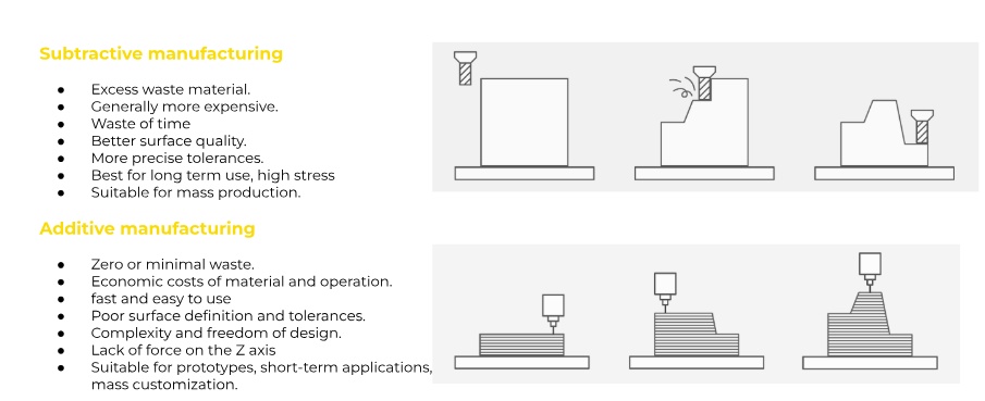
Source: (Fab Lab, https://fablabbcn-projects.gitlab.io/learning/educational-docs/fabacademy/classes/05-3DScanningandPrinting/)
Various 3D Printing Technologies
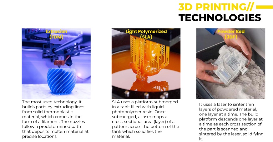
Source: (Fab Lab, https://fablabbcn-projects.gitlab.io/learning/educational-docs/fabacademy/classes/05-3DScanningandPrinting/)
The following two images are 3D printing technologies charts, detailing process families (Vat Photopolymerization, Material Extrusion, Material Jetting, Binder Jetting, Sheet lamination, and Directed energy deposition). It includes common abbreviations, typical material forms, and examples of each technology, giving a more comprehensive overview of additive manufacturing processes.
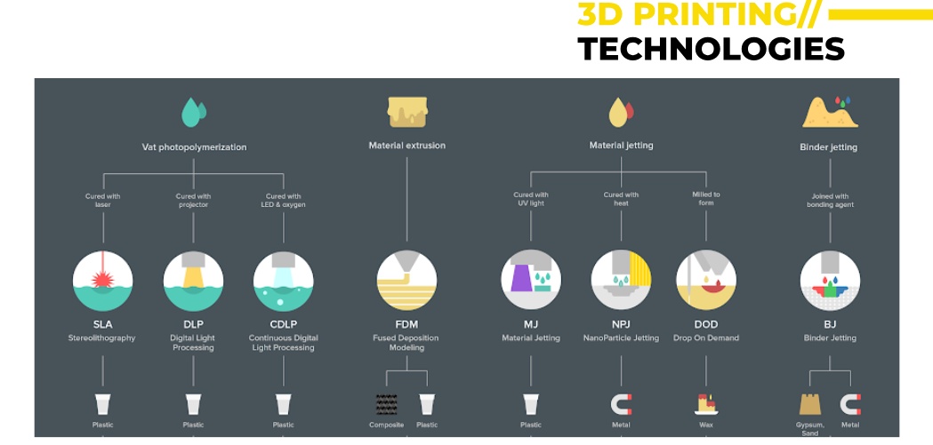
Source: (Fab Lab, https://fablabbcn-projects.gitlab.io/learning/educational-docs/fabacademy/classes/05-3DScanningandPrinting/)
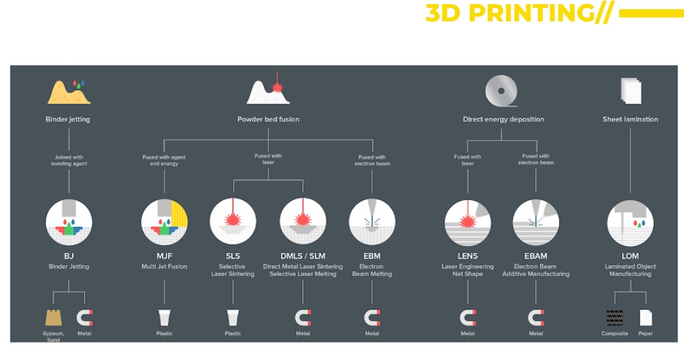
Source: (Fab Lab, https://fablabbcn-projects.gitlab.io/learning/educational-docs/fabacademy/classes/05-3DScanningandPrinting/)
This puts printable materials into categories showing that over the years 3D printing accommodates diverse materials and applications like biomedicine, construction, automotive and aerospace to name a few.
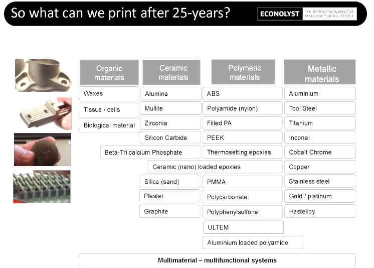
Source: (Fab Lab, https://fablabbcn-projects.gitlab.io/learning/educational-docs/fabacademy/classes/05-3DScanningandPrinting/)
The Basic Slicing Process
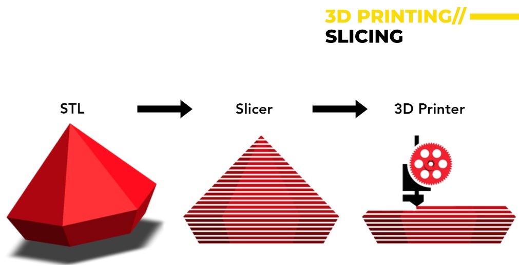
Source: (Fab Lab, https://fablabbcn-projects.gitlab.io/learning/educational-docs/fabacademy/classes/05-3DScanningandPrinting/)
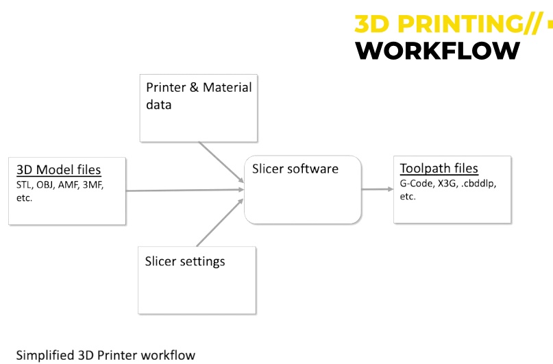
This explains how 3D model files get converted into printable files. First we need to input the files to slicer software such as Cura, or Bambu studio. Then we turn the STL into a G-code which is like a list of co-ordinates. Then we are able to print in our chosen material (organic, ceramic, polymeric, metallic).
Source: (Fab Lab, https://fablabbcn-projects.gitlab.io/learning/educational-docs/fabacademy/classes/05-3DScanningandPrinting/)
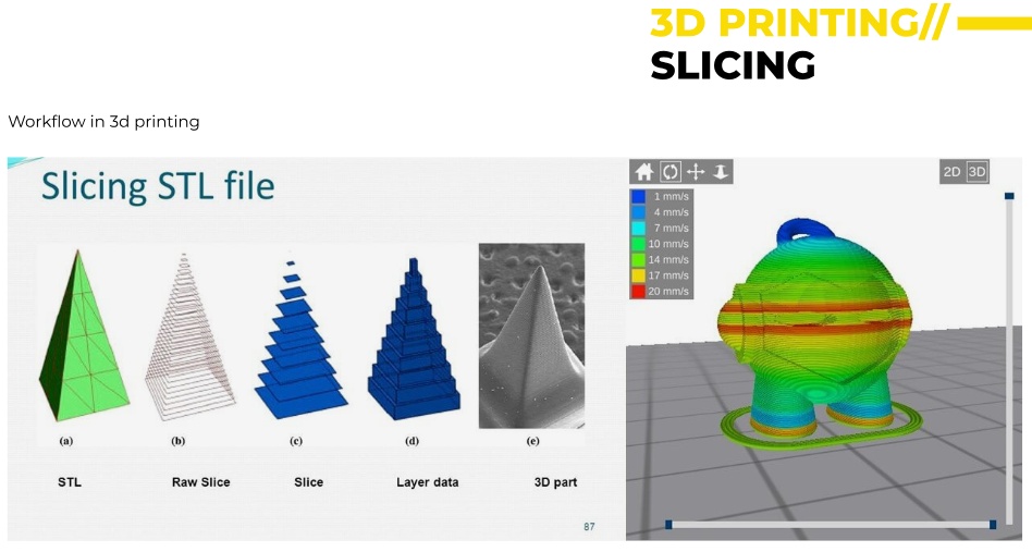
This shows the slicing process in 3D. Starting with the original model in .STL file, then slicing into horizontal layers and then smoothing out the layers. Then a layer by layer breakdown and then the final result. On the right side shows a color-coded visualisation of slicing showing different speeds of the different parts based on what is optimal for each part.
Source: (Fab Lab, https://fablabbcn-projects.gitlab.io/learning/educational-docs/fabacademy/classes/05-3DScanningandPrinting/)
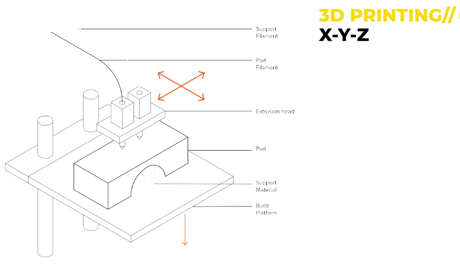
The following image Illustrates the movement of a 3D printer in three dimensions, where to for the X-Y Movement the extrusion head moves left-right (X) and front-back (Y), and for the Z Movement the build platform moves up and down, controlling layer height.
Source: (Fab Lab, https://fablabbcn-projects.gitlab.io/learning/educational-docs/fabacademy/classes/05-3DScanningandPrinting/)
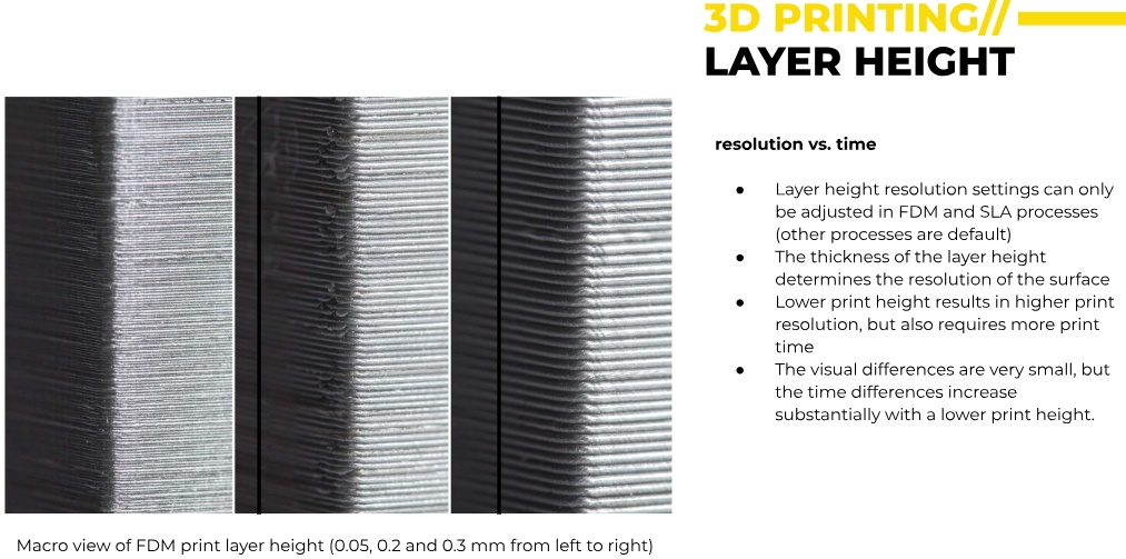
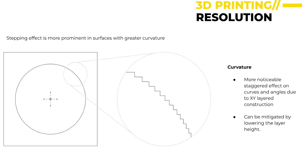
This image explains the correlation between print resolution is affected by layer height. Lower layer height = smoother finish but higher print time and a higher layer height means faster print but more visible layer lines.
Source: (Fab Lab, https://fablabbcn-projects.gitlab.io/learning/educational-docs/fabacademy/classes/05-3DScanningandPrinting/)
A layer height of 0.05mm would create very fine resolution, whereas 0.3mm would be faster but have visible stepping effects.
Source: (Fab Lab, https://fablabbcn-projects.gitlab.io/learning/educational-docs/fabacademy/classes/05-3DScanningandPrinting/)
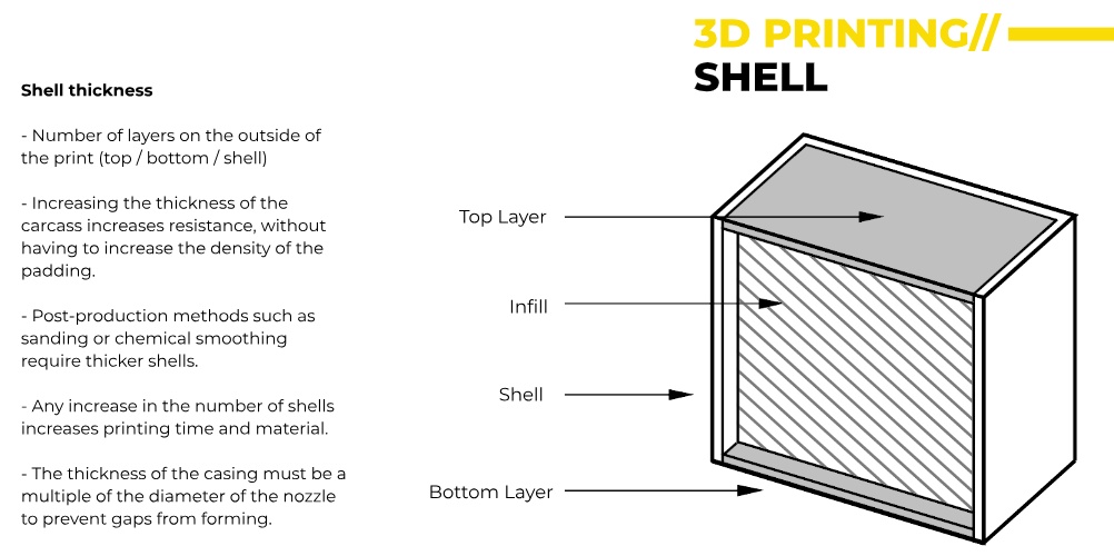
Increasing shell thickness improves durability without increasing internal infill. More shell layers take longer and add more material but it adds strength. (Post-processing considerations: Sanding, chemical smoothing, and painting require thicker shells).
Source: (Fab Lab, https://fablabbcn-projects.gitlab.io/learning/educational-docs/fabacademy/classes/05-3DScanningandPrinting/)
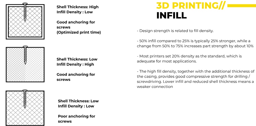
Regarding 'Infill' in the following image, a higher infill percentage strengthens the part but increases material use. Standard infill is 20%, but increasing to 50% makes it 25% stronger. Beyond 75% infill, strength gain is minimal, but print time significantly increases. 10% is often strong enough.
Source: (Fab Lab, https://fablabbcn-projects.gitlab.io/learning/educational-docs/fabacademy/classes/05-3DScanningandPrinting/)
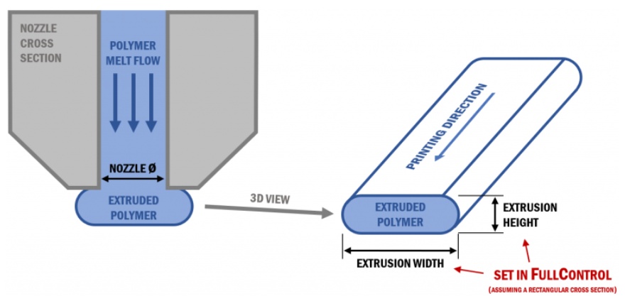
In 3D Printing a polymer is melted and extruded through a nozzle. Important parameters are Nozzle Diameter which controls extrusion width, extrusion width & height: determines the layer resolution (as well as surface smoothness and layer adhesion) and printing direction affects how layers bond together.
Source: (Fab Lab, https://fablabbcn-projects.gitlab.io/learning/educational-docs/fabacademy/classes/05-3DScanningandPrinting/)
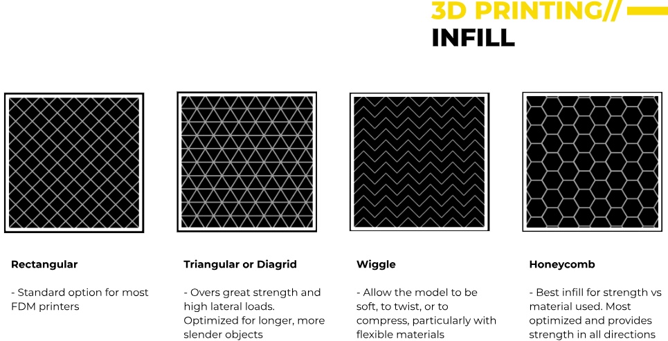
Infill provides internal support and strength to 3D printed parts. A Rectangular pattern is standard for most FDM printers. A Triangular / Diagrid is good for handling lateral loads, which is better for longer objects. The Wiggle infill is common for flexible materials that need to compress or twist, and the Honeycomb is best for strength-to-material ratio in all directions.
Source: (Fab Lab, https://fablabbcn-projects.gitlab.io/learning/educational-docs/fabacademy/classes/05-3DScanningandPrinting/)
In FDM-FFF (Fused Deposition Modeling / Fused Filament Fabrication), the print orientation is important as it affects accuracy, print time & material usage. It also Influences surface quality & finish. In the image two cylindrical parts with different orientations show how layer direction affects strength and surface finish.

Source: (Fab Lab, https://fablabbcn-projects.gitlab.io/learning/educational-docs/fabacademy/classes/05-3DScanningandPrinting/)
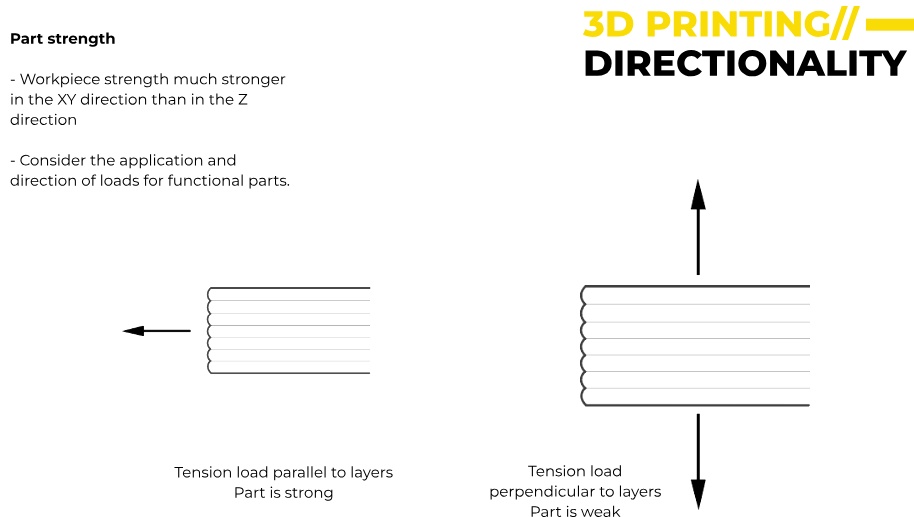
The following graphic shows how 3D printed parts are much stronger in the XY direction than in the Z direction. This is because the material is continuously extruded and fused layer by layer whereas in the Z Direction layers are stacked on top of each other with weaker inter-layer bonding.
Source: (Fab Lab, https://fablabbcn-projects.gitlab.io/learning/educational-docs/fabacademy/classes/05-3DScanningandPrinting/)
Support Structures
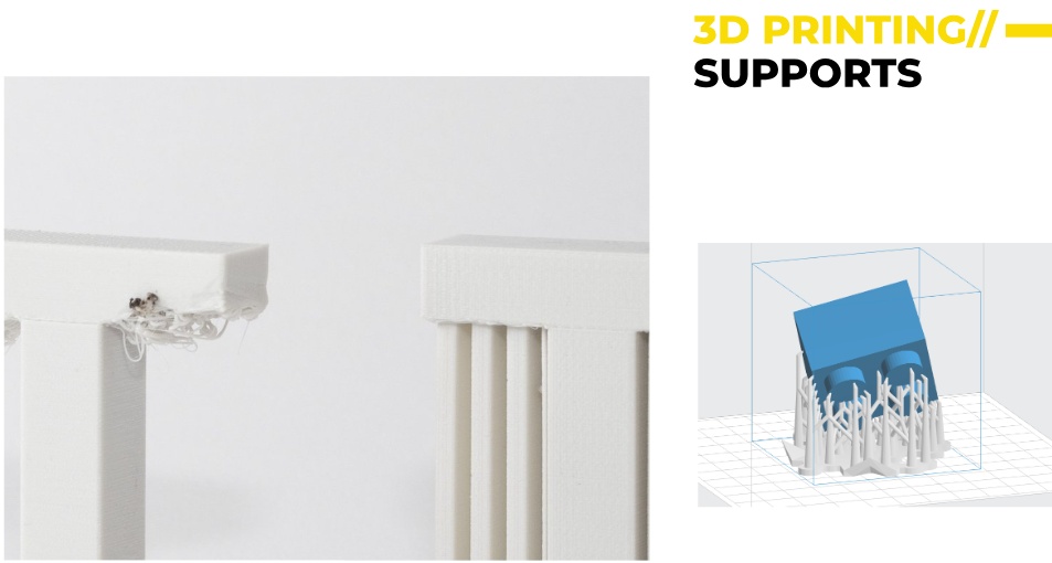
The image on the left shows poor support settings, leading to material drooping and defects and on the right properly structured supports provide better surface quality.
(Source: FabLab BCN Documentation: https://fablabbcn-projects.gitlab.io/learning/educational-docs/fabacademy/classes/05-3DScanningAndPrinting/ )
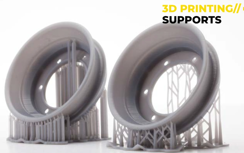
3D Printing Supports are needed as some overhangs and bridges cannot print without additional material to hold them up. Gravity causes defects in parts with large overhangs. Some supports are tree-like designed to use minimal material, others are grid-based that are more rigid. They are helpful when printing complex geometries.
(Source: FabLab BCN Documentation: https://fablabbcn-projects.gitlab.io/learning/educational-docs/fabacademy/classes/05-3DScanningAndPrinting/ )
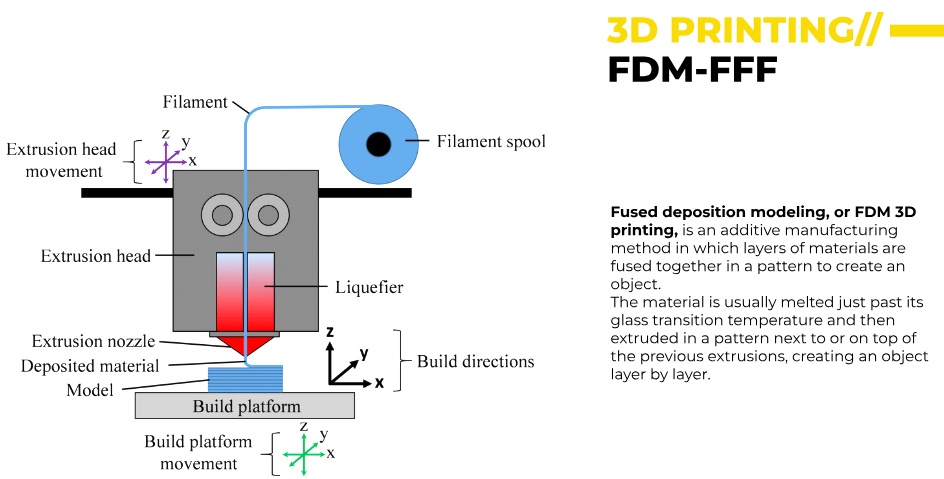
FDM-FFF (Fused Deposition Modeling - Fused Filament Fabrication) is a process where layers are fused together. It works best with thermoplastic materials like PLA, ABS and PETG. It works as the filament is fed from a spool into the extrusion head. A liquefier heats the material past its glass transition temperature and the extrusion nozzle deposits material layer by layer to form the model.
(Source: FabLab BCN Documentation: https://fablabbcn-projects.gitlab.io/learning/educational-docs/fabacademy/classes/05-3DScanningAndPrinting/ )
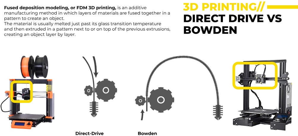
There are two types of filament feeding mechanisms in FDM 3D printers. The Direct Drive, where the extruder motor is directly mounted on the print head. It provides better filament control, and more accurate extrusion (but adds weight to the print head). With the Bowden mechanism, the extruder motor is placed away from the print head, and the filament is pushed through a tube. It reduces moving weight, but is less precise Direct Drive is better for flexible materials, while Bowden is lighter and faster for general printing.
(Source: FabLab BCN Documentation: https://fablabbcn-projects.gitlab.io/learning/educational-docs/fabacademy/classes/05-3DScanningAndPrinting/ )
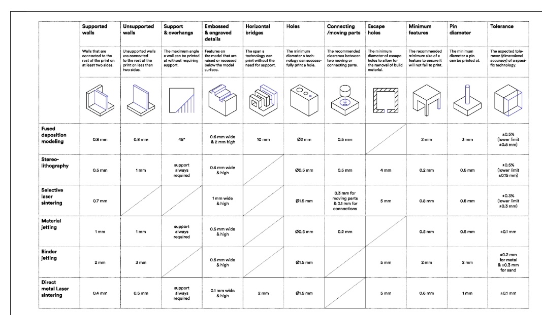
The following image compares different 3D printing technologies: FDM (Fused Deposition Modeling) is best for affordable prints but has lower precision. SLA (Stereolithography) is high resolution, but requires support structures. SLS (Selective Laser Sintering) don't need supports, and is great for complex shapes. Material Jetting & Binder Jetting: High-detail prints but expensive. DMLS (Direct Metal Laser Sintering): Used for metal printing.
(Source: FabLab BCN Documentation: https://fablabbcn-projects.gitlab.io/learning/educational-docs/fabacademy/classes/05-3DScanningAndPrinting/ )
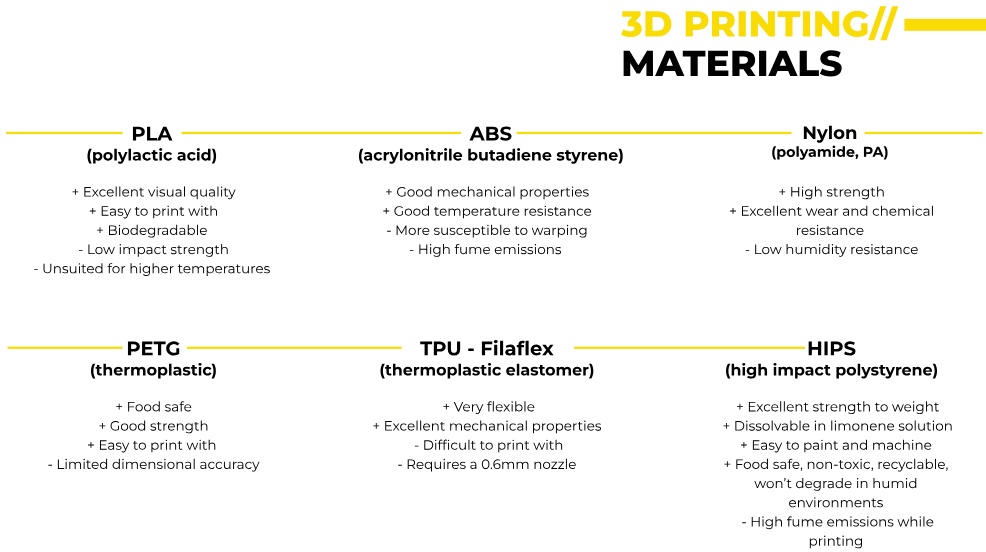
The following table looks at the features of various filament types in more detail: PLA: Easy to print, biodegradable, but weak under heat. ABS: Stronger than PLA, but warps easily. Nylon: High strength, great wear resistance, but absorbs moisture. PETG: Food safe, strong, and heat-resistant. TPU (Filaflex): Flexible, used for soft, rubber-like parts. HIPS: Good strength, dissolvable in limonene, used as support material.
(Source: FabLab BCN Documentation: https://fablabbcn-projects.gitlab.io/learning/educational-docs/fabacademy/classes/05-3DScanningAndPrinting/ )
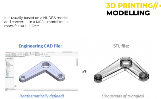
In modelling, CAD Files on the left are NURBS based and are created using parametric modelling. So shapes are smooth and mathematically defined. STL Files are converted into triangular meshes. They approximates smooth surfaces but can lose detail.
(Source: FabLab BCN Documentation: https://fablabbcn-projects.gitlab.io/learning/educational-docs/fabacademy/classes/05-3DScanningAndPrinting/ )
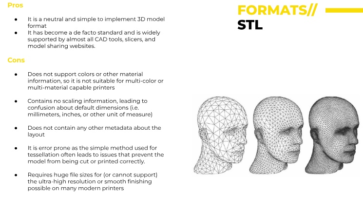
STL Format: Simple and widely used in 3D printing. Compatible with most CAD and slicing software. However, there is no color or material information, no scaling or unit information, prone to errors and large file sizes.
(Source: FabLab BCN Documentation: https://fablabbcn-projects.gitlab.io/learning/educational-docs/fabacademy/classes/05-3DScanningAndPrinting/ )
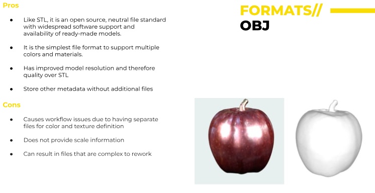
OBJ files are a step up from STL, offering color, texture, and higher resolution, but they require additional files for full functionality and have no scale information and requires separate files for colors and textures, leading to management issues.
(Source: FabLab BCN Documentation: https://fablabbcn-projects.gitlab.io/learning/educational-docs/fabacademy/classes/05-3DScanningAndPrinting/ )
AMF & 3MF File Formats
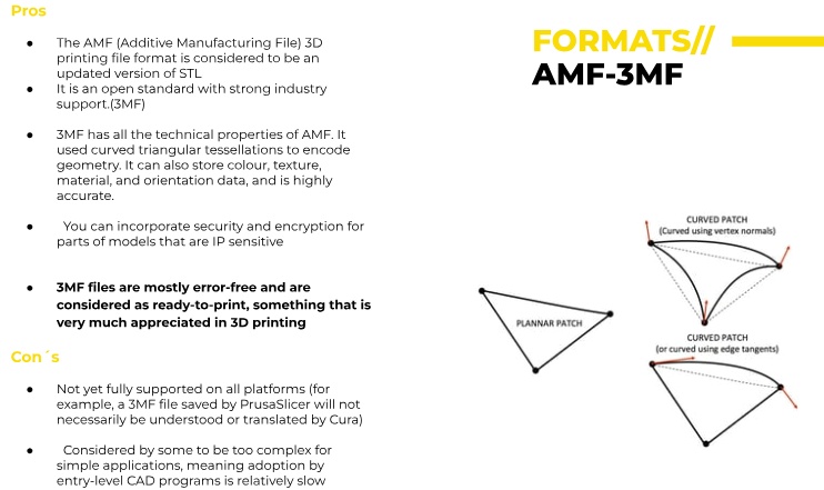
It is more advanced than STL, more accurate geometry representation (It uses curved triangular tessellations), improving precision and reducing file size compared to STL. It supports color & material information, texture mapping, object Orientation Data, security & encryption, and is ready to print free of error, but there is limited software support. Also some slicers (Cura) do not fully support all features. It can also be complicated for simple printing tasks.
(Source: FabLab BCN Documentation: https://fablabbcn-projects.gitlab.io/learning/educational-docs/fabacademy/classes/05-3DScanningAndPrinting/ )
Examples of 3D Printing
The following few images are some beautiful examples of 3D printing:
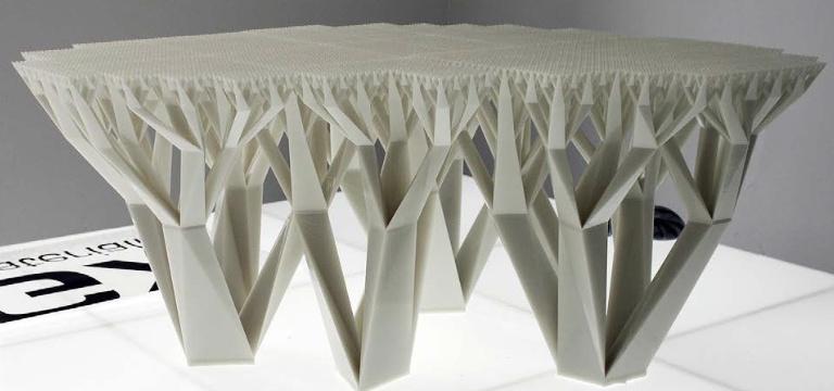
(Source: FabLab BCN Documentation: https://fablabbcn-projects.gitlab.io/learning/educational-docs/fabacademy/classes/05-3DScanningAndPrinting/ )
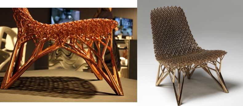
(Source: FabLab BCN Documentation: https://fablabbcn-projects.gitlab.io/learning/educational-docs/fabacademy/classes/05-3DScanningAndPrinting/ )
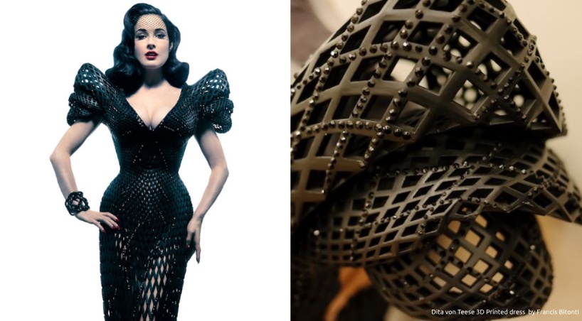
(Source: FabLab BCN Documentation: https://fablabbcn-projects.gitlab.io/learning/educational-docs/fabacademy/classes/05-3DScanningAndPrinting/ )

(Source: FabLab BCN Documentation: https://fablabbcn-projects.gitlab.io/learning/educational-docs/fabacademy/classes/05-3DScanningAndPrinting/ )
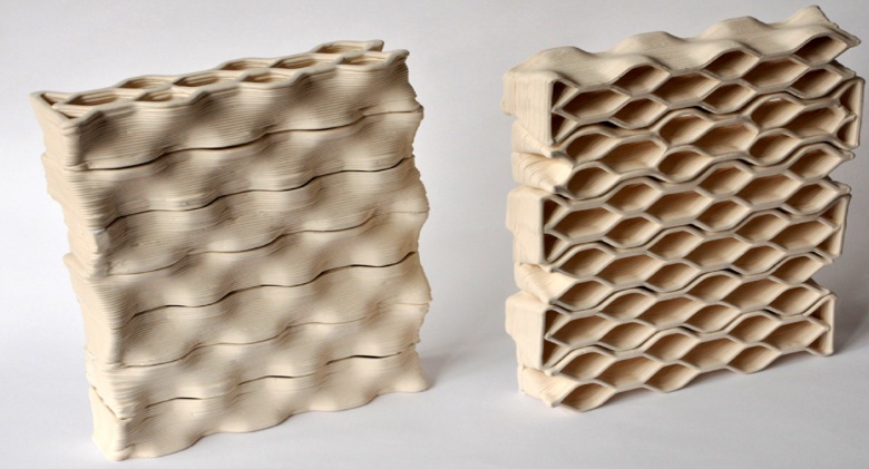
(Source: FabLab BCN Documentation: https://fablabbcn-projects.gitlab.io/learning/educational-docs/fabacademy/classes/05-3DScanningAndPrinting/ )
This video shows Yulia demonstrating at FabLab the actual usage of a 3D Ender printer.
A Note on 3D Resin Printing
We also looked at and printed out an object on resin printer. I found some information on the Tablehammer.
What is resin printing?
Resin 3D printing, also known as SLA (stereolithography) printing, uses UV-curable liquid resin to create highly detailed and accurate models. It is well suited for miniature tabletop games because it can create intricate details and smooth surfaces.
Resin printing typically requires post-processing, such as cleaning and curing, to remove excess resin and harden the parts completely. Resin printing can be more expensive than other forms of 3D printing because of the cost of the resin and the need for specialized equipment like UV curing chamber. Safety precautions should be taken when working with resin as it can be toxic and harmful if ingested or inhaled.
The difference between resin-based 3D printing and filament-based 3D printing is visible when you pull the object from the bed.
Below is an image of a Resin print Vs a Filament print on the right showing the comparative printing profiles of each method:
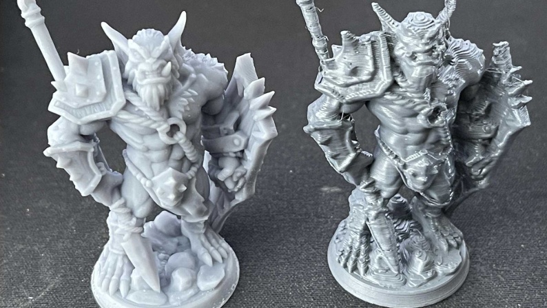
Objects produced through resin printing can be more detailed and consistent with fewer printing artifacts. Objects produced with filament printing, however, have better engineering properties and a wider range of materials and styles. Like some filaments, resins are irritants and poison hazards. Wearing gloves and having adequate ventilation is a must. Users must be trained in proper safety procedures when handling and disposing of resins.
The biggest differences between FDM and resin printing are:
- Print Quality: Resin printers > higher quality prints, fine details and high resolution.
- Print Speed: FDM printers > faster than resin printers, as they use a filament that is melted and extruded onto the build plate. Resin printers, on the other hand, cure liquid resin layer by layer, which takes longer.
- Materials: FDM printers use filaments made of thermoplastics such as ABS, PLA, and TPU, while resin printers use liquid photopolymer resins.
- Post-Processing: FDM prints typically requires cleaning, sanding, and painting to achieve a smooth finish, while resin prints have a better surface quality and require less post-processing.
- Cost: Resin printers > more expensive than FDM printers, and the resins used in resin printing are also more expensive than filaments used in FDM printing.
- Size and Build Volume: FDM printers generally have larger build volumes and can print larger models, while resin printers are typically smaller and have smaller build volumes.
- Safety: Resin printing requires precautions for handling and using UV light during the printing process, FDM printing is considered safer as it uses lower temperature and don't emit UV light.
- Detail and complexity: Resin printing is better suited for printing small, detailed, and complex models while FDM printing is better suited for larger and simpler models.
How does the resin printing process work?
The resin 3D printing process, also known as SLA (stereolithography) printing, works by using a UV laser to cure and harden liquid resin. The process begins by filling a build tray with liquid resin. The build tray is then placed into the printer, which is equipped with a UV laser and a moving platform.
The printer uses the UV laser to cure a thin layer of the resin, typically 0.05-0.1mm in thickness, by selectively exposing specific areas of the resin to UV light. The moving platform then drops down by the thickness of one layer and the process is repeated. This process continues until the entire model has been built up layer by layer.
Once the model has been printed, it is removed from the build tray and cleaned to remove any uncured resin. The model is then placed in a UV curing chamber to complete the curing process. After curing, the model is then ready for use or further post-processing, such as sanding or painting.
The slicing software that we use for Resin printing are: Chitubox or Lychee
Individual Assignment
In class we were shown 3D objects. One of them was an impossible passthrough triangle after seeing it. There was something extremely satisfying about it for all of us. As can be seen from the image, there are two pieces, and somehow, they passthrough each other in two directions when picked up making a satisfying sound and movement.
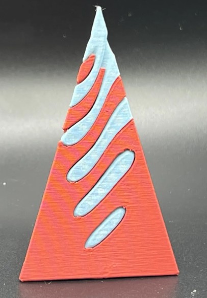
How to make an impossible passthrough on Fusion 360
On the YZ Plane a TOP view I drew a circle and in it and the start of a shape which I was later going to pattern and extrude.
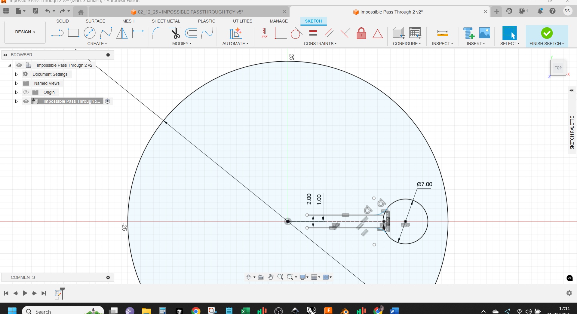
I used pattern tool to copy the design around
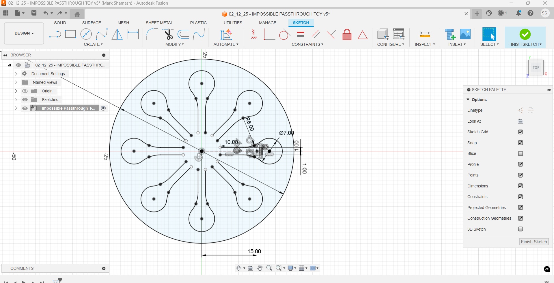
I used the Coincident tool to join all the edges. (This one little aspect had taken me many hours as it could not solve for the corners and I kept re-doing it until it suddenly worked as it should).
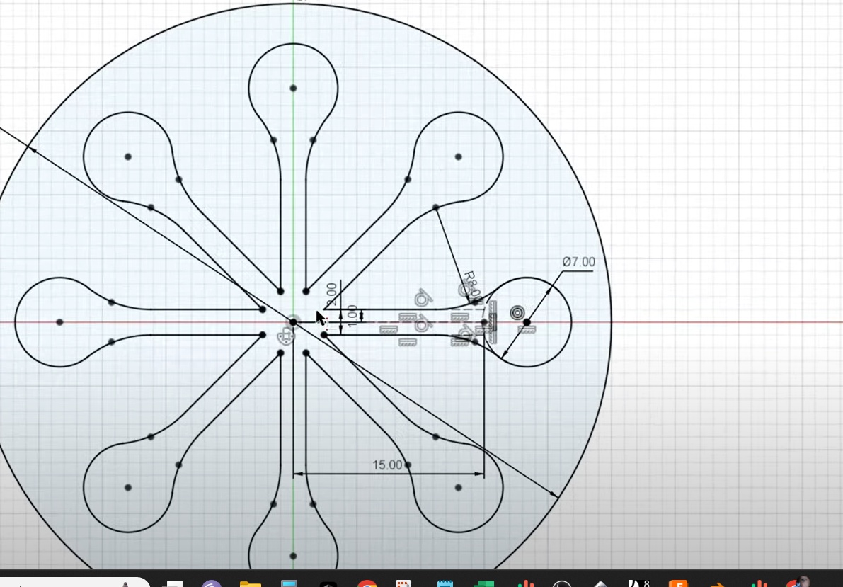
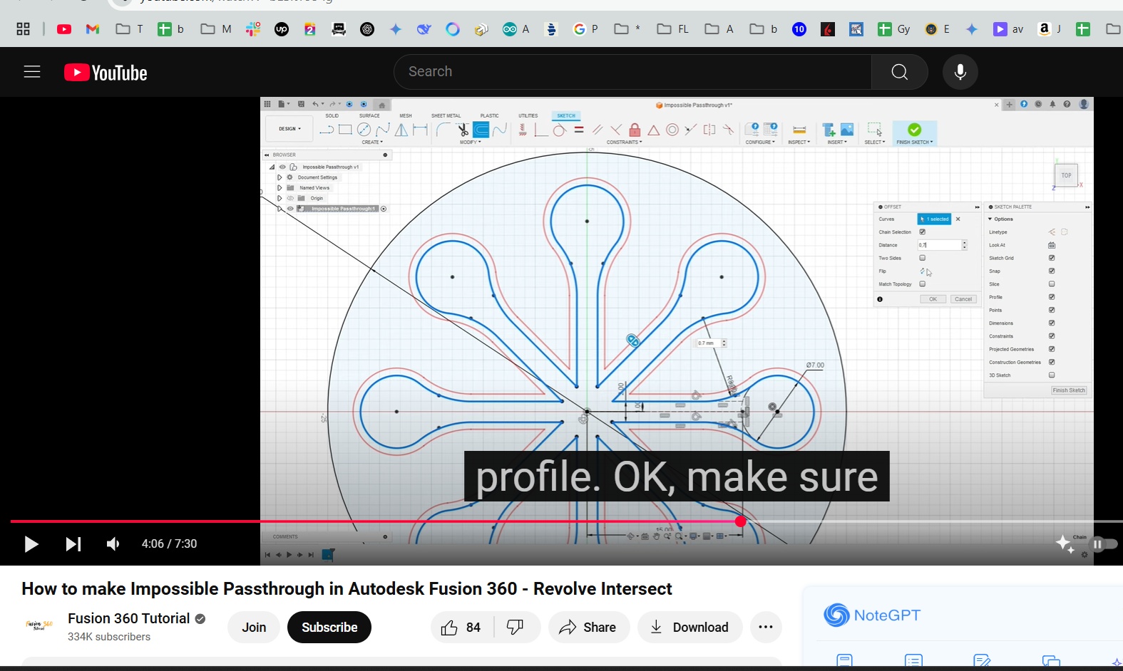
I then used an offset command to offset outward so there is a gap between the outer and inner body
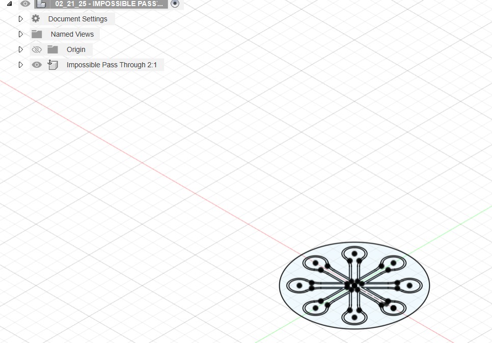
Here we change the view to visualise before extrusion
and then draw a vertical line which will be the height of the object
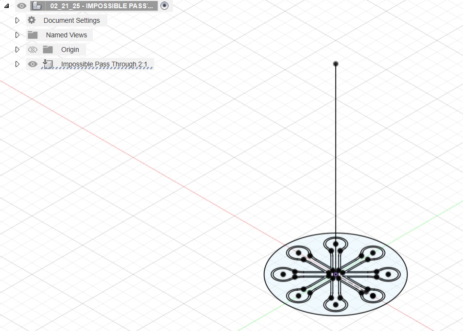
Then selecting just the outer body, I use a Sweep to extrude following the line
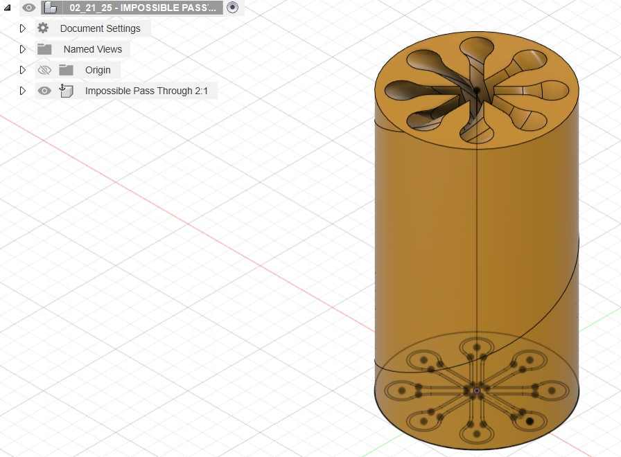
Then I selected just the inner body to see how it looks
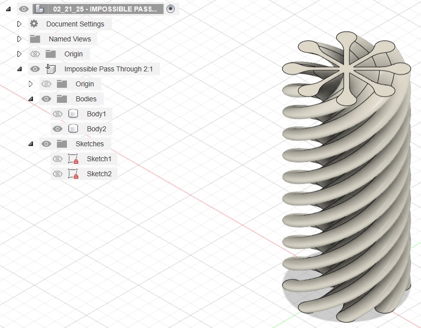
Now selecting both bodies to see how the geometries fit together
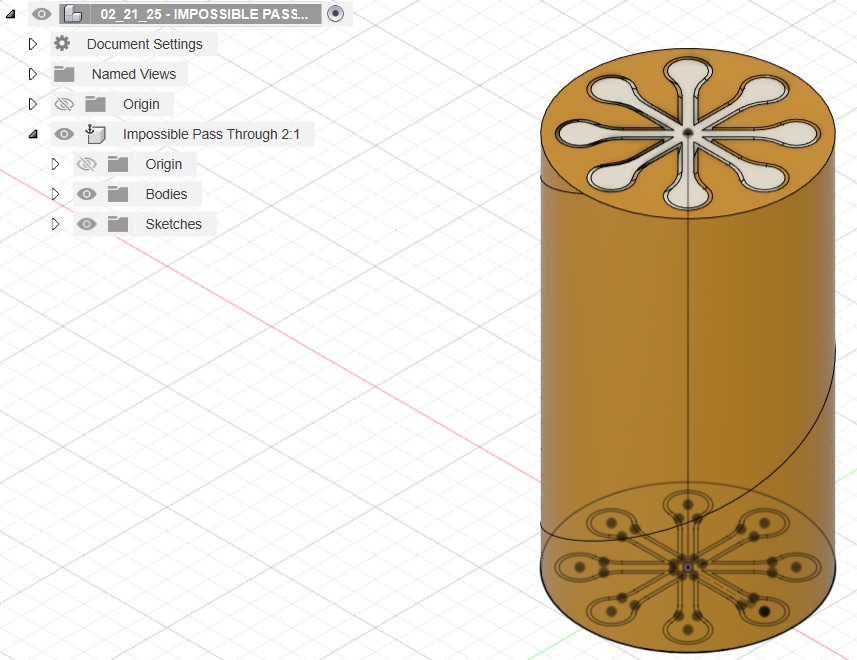
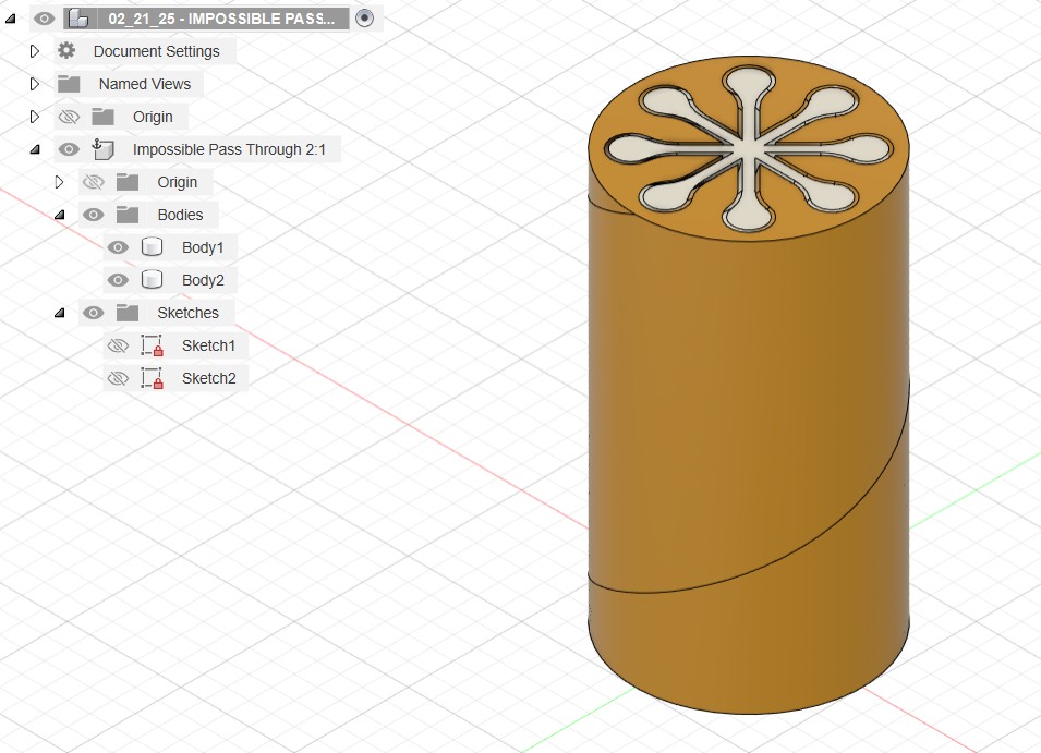
Fully completed design without drawing lines
Preparing for Print
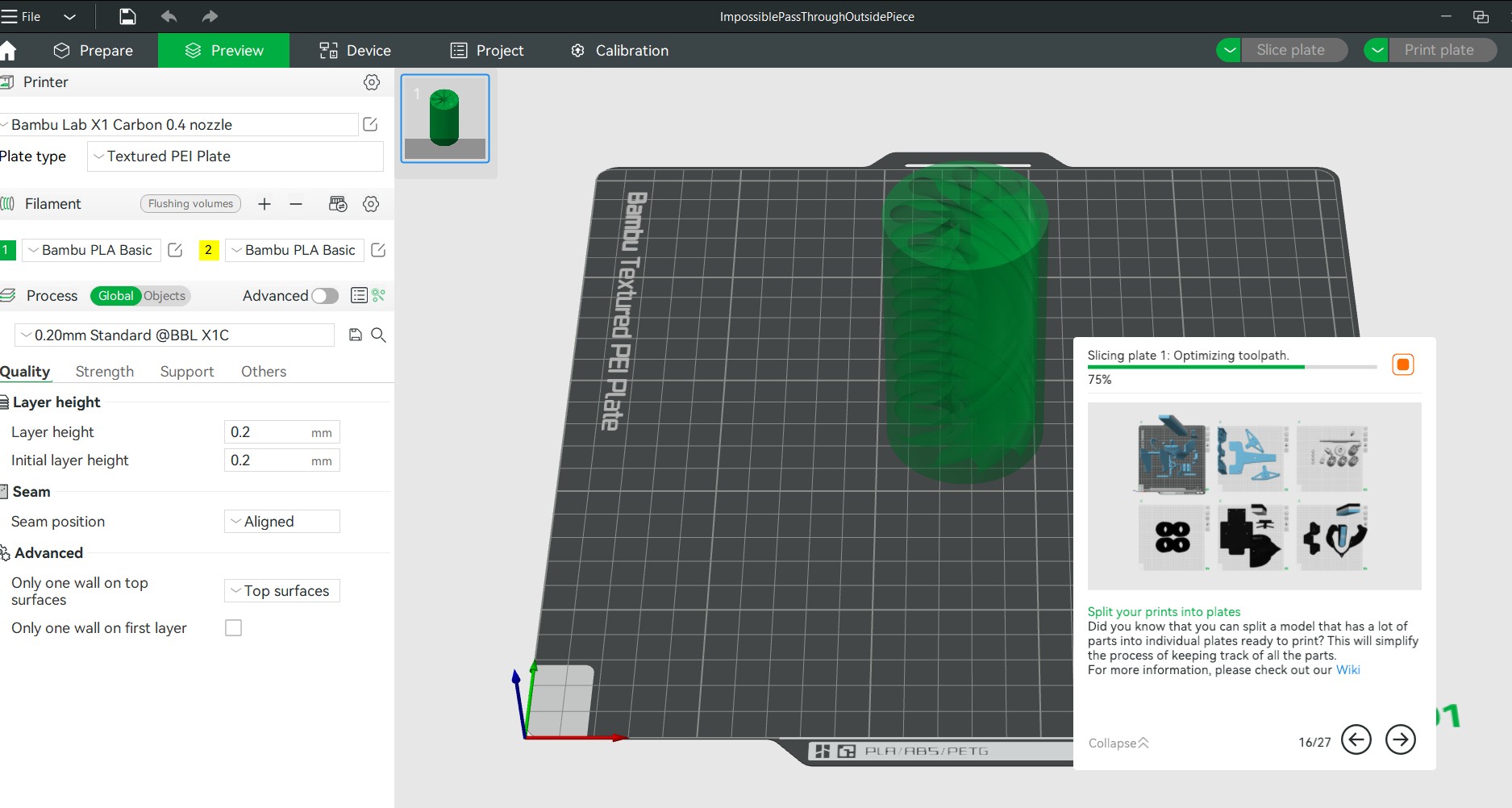
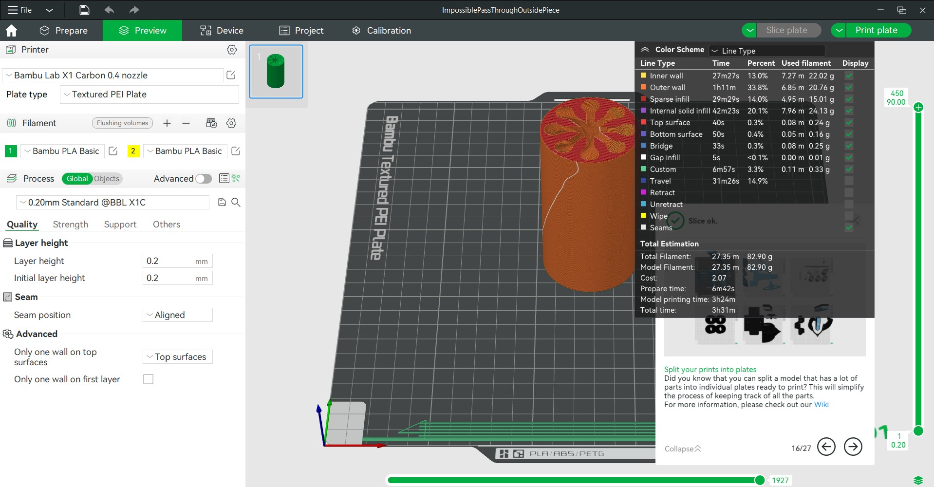
First I took these Fusion 360 Impossible Passthrough files and exported them as .STL files. I opened them in Bambu Studio, made sure I had selected the correct printer and nozzle size and pressed the slice button. This is when the software figures out how its going to print out the object and creates G-code which are the instructions on where to move.

The Printing Process
I saved these files onto a micro SD and inserted it into the X1 Carbon 3D printer. I found my file and pressed print.
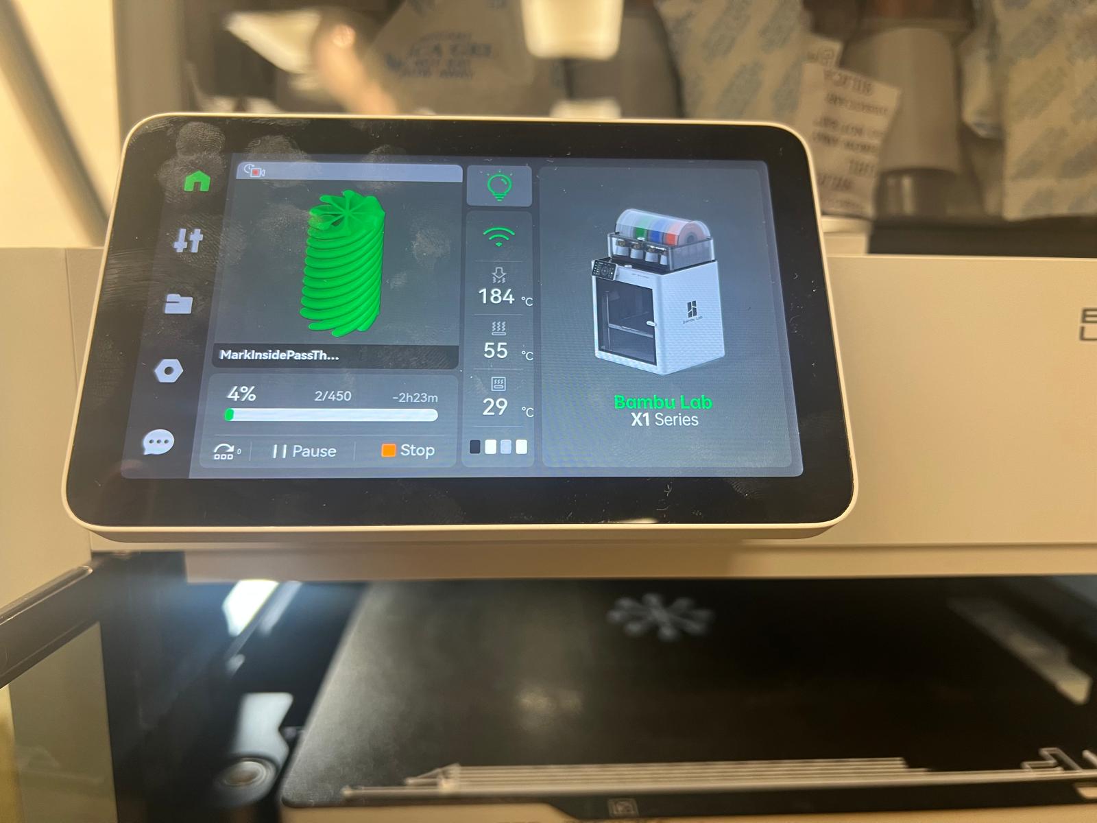
Very shortly after it started I began receiving error messages about debris on the Z axis.
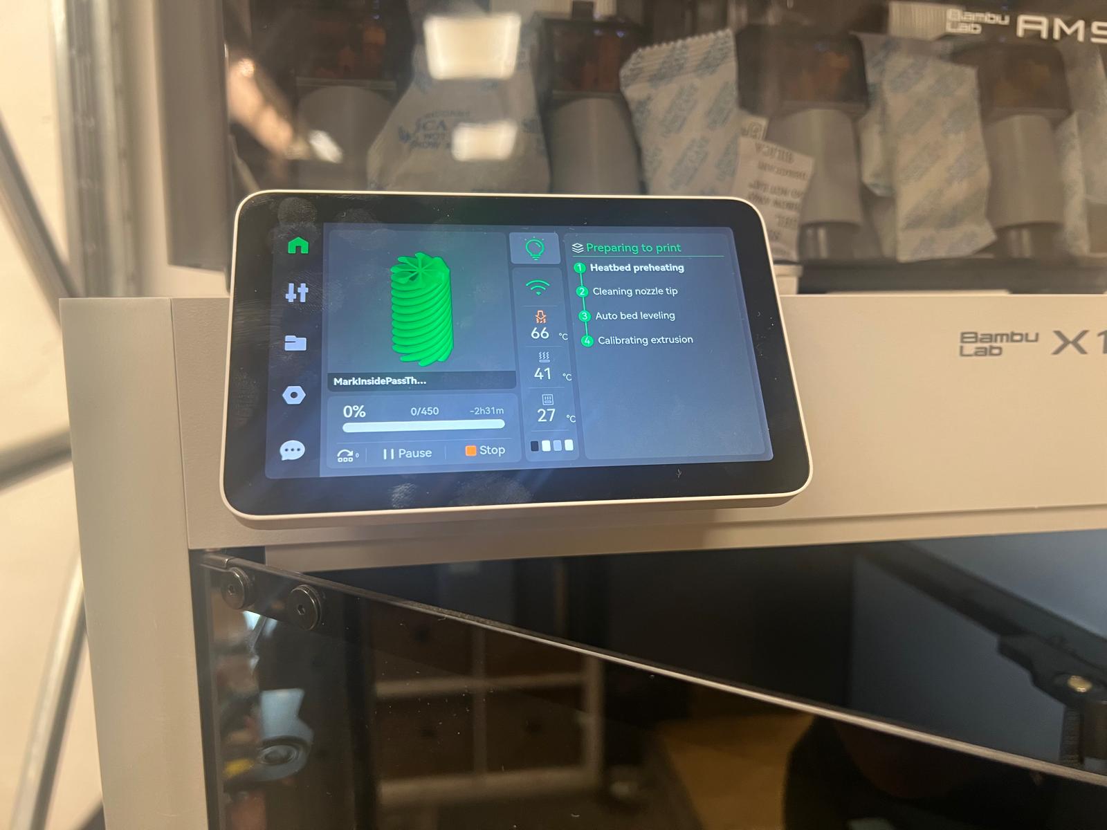
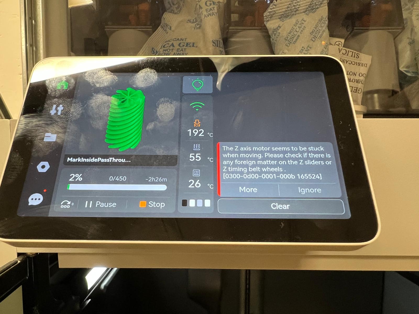
This happened a few times, and then I switched off the machine and tried to clean all the dirt and loose pieces out. It didn't work and then I found bigger pieces deep inside.
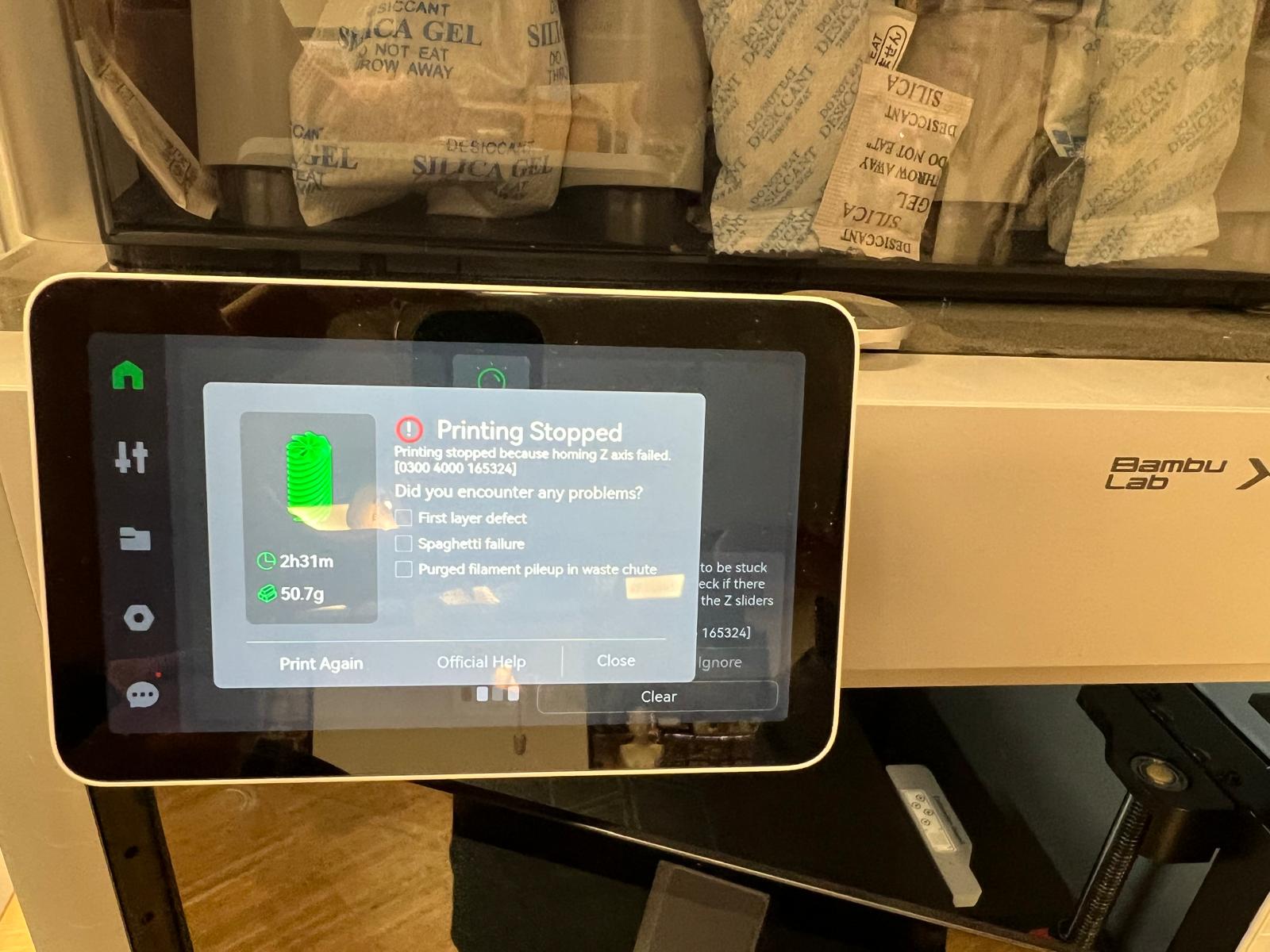
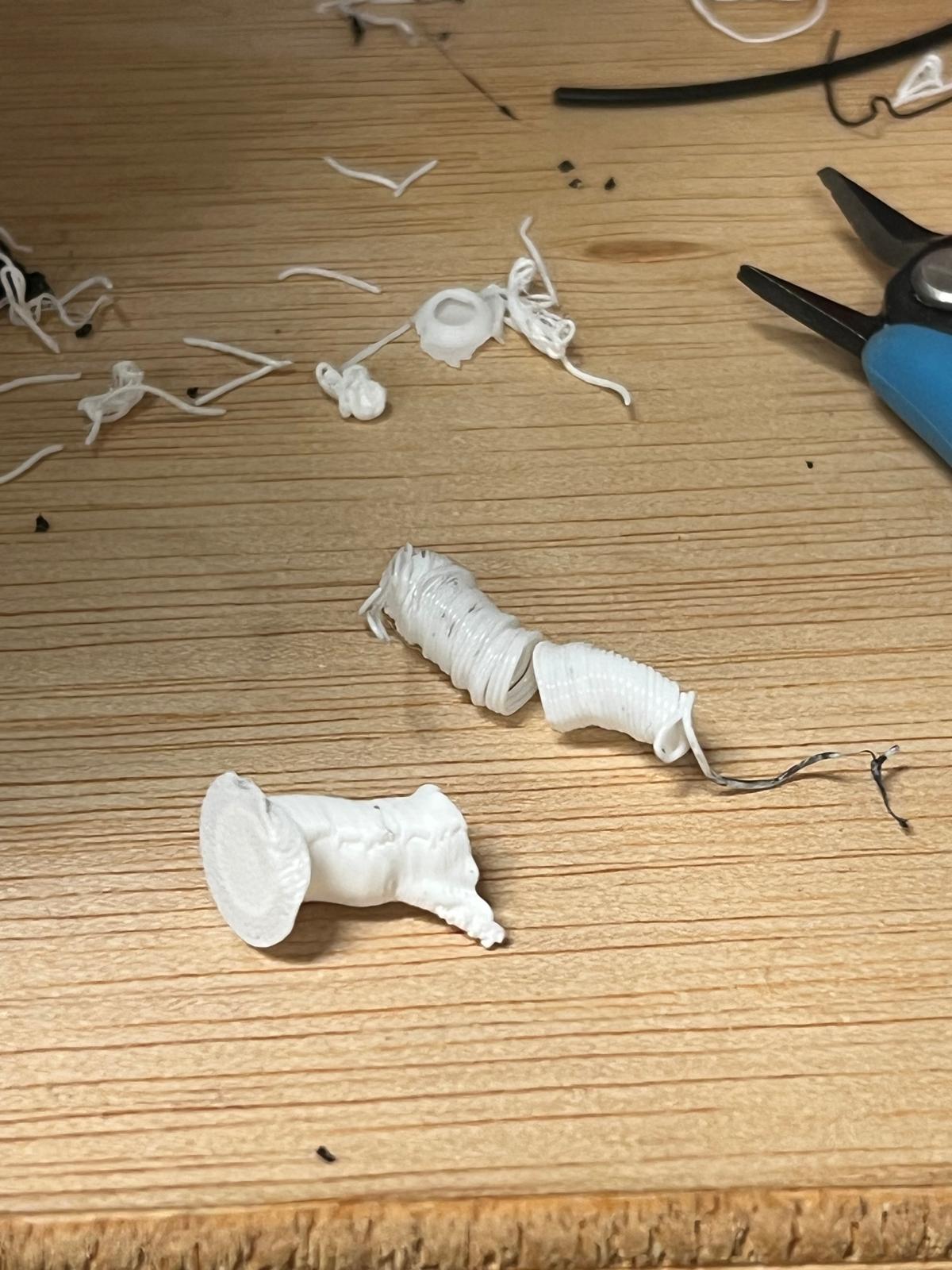
After getting rid of that it worked perfectly.
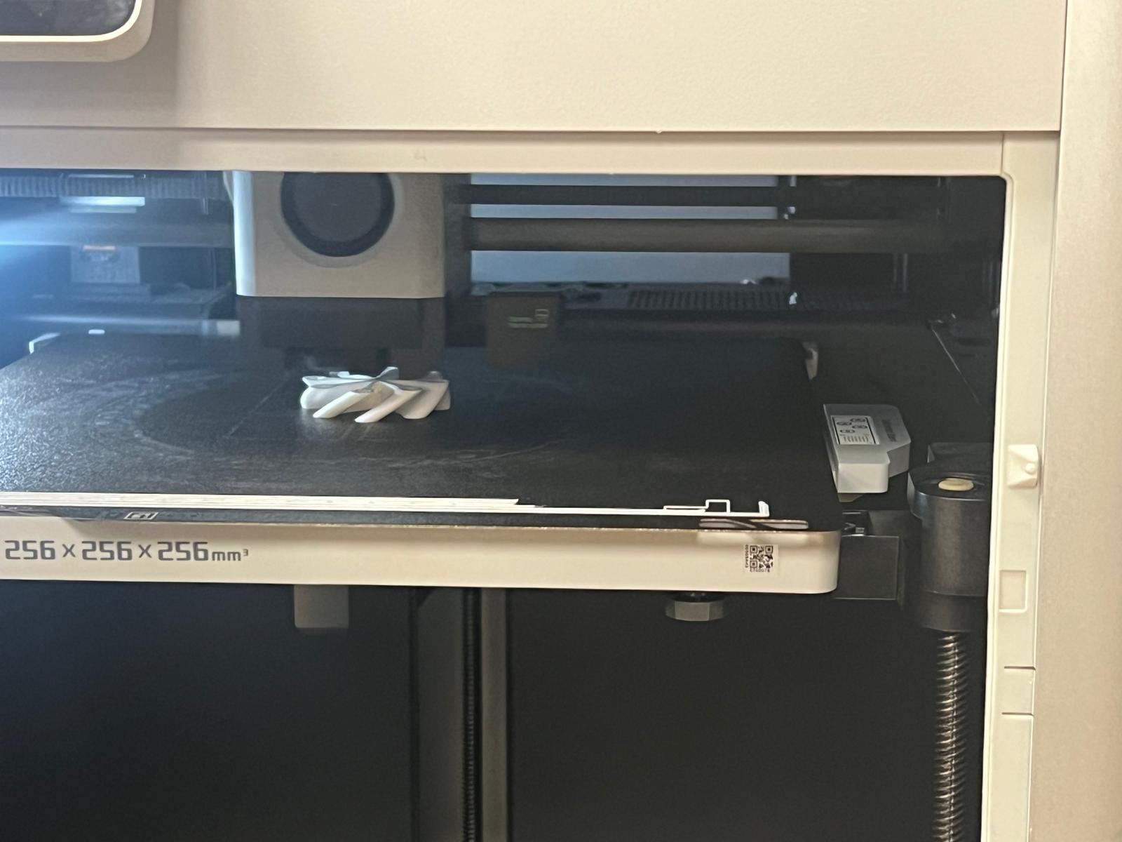
My print was 2 hours for one piece, and then 3.5 hours for a second piece – Finally the inner and outer piece of the passthrough is ready. When I saw the other piece I initially panicked as I thought that it was closed shut and that I had made an error in my design…but it worked!
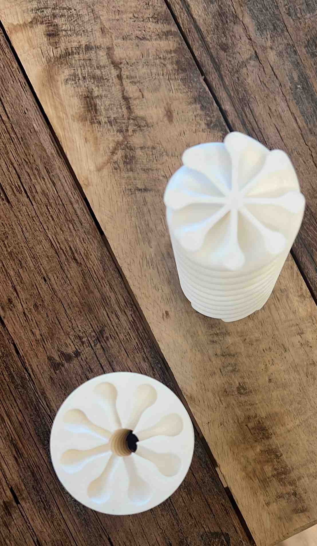
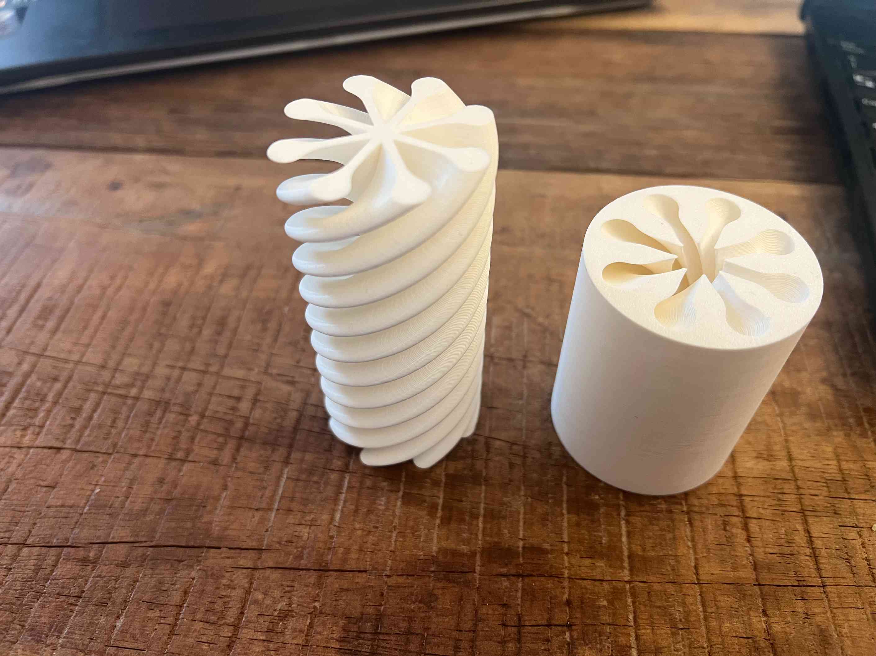
I realised that I had chosen such a steep angle that it appeared completely closed off. See photos and video above.
Also, you may notice that the outer layer is shorter than the inner layer. This is because we ran out of filament.
Design Files
- Impossible Pass Fusion 360 .f3d
- Impossible Pass Mesh File .stl
- Sliced Bambu File Outer Piece .3mf
- Sliced Bambu File Inner Piece .3mf
Git Repository Issues and Resolution
Unfortunately I could not push all changes to my remote repo as I had hoped on Tuesday. Even the mighty Daniel could not fix it today and I hope we can solve it on Wednesday as I feel unbalanced being unable to push. Daniel tried many tactics to push to the repo and then decided to deprecate my problematic repo and clone a new repo from the remote server. Unfortunately, it didn't work for some reason and we decided to tackle it the next day. Today, Daniel came in with renewed energy after processing all the possibilities while he slept. It turned out that in the version of Git that I had there was a known bug in windows. After Daniel upgraded to the latest version it suddenly worked. I am incredibly grateful. Thank you! Thank you! Thank you, Daniel!
3D Scanning
On the scanning part, like the 3D printing part, Josep & Daniel gave us the first class on scanning on Thursday describing history and different techniques used. They then demonstrated the Revoscan device.
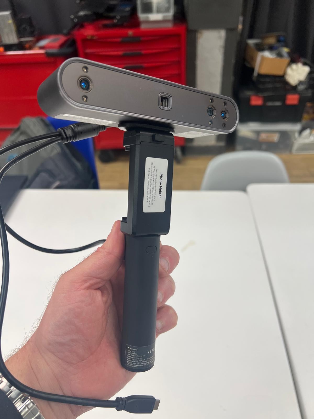
This is how the equipment looks:

It is a very simple and intuitive device. You connect the Revopoint to a phone with a C cable and it switches on and ready to point and shoot.
One must move around the object very very slowly to get a good result.
This would be a perfect result:
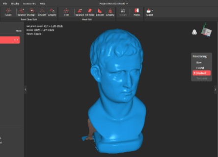
And this was the actual result:
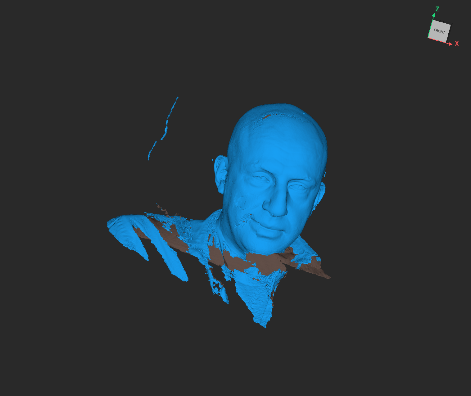
In reality unless a scan is done perfectly which is almost impossible, there will be plenty of artefacts as you can see from my image. These images are referred to as polygons and as I understood it is time consuming to clean it up. I am a complete beginner in all CAD softwares and so I didn't attempt to clean up my image in the short time I had as I had a list of other things to do.
Paste Printing Project
I also created a file for a paste print. I decided to create a pen & pencil holder in Fusion 360 to print as a ceramic as I knew that a structure of that shape would not collapse.
Spoiler alert. The day went badly for me, in the sense that it ate up a lot of time for relatively small gains. It took me and I think others until 4pm individually to actually create an .STL file which we could then generate a code for in Mamba.
I create a file in fusion and exported it to Rhino:
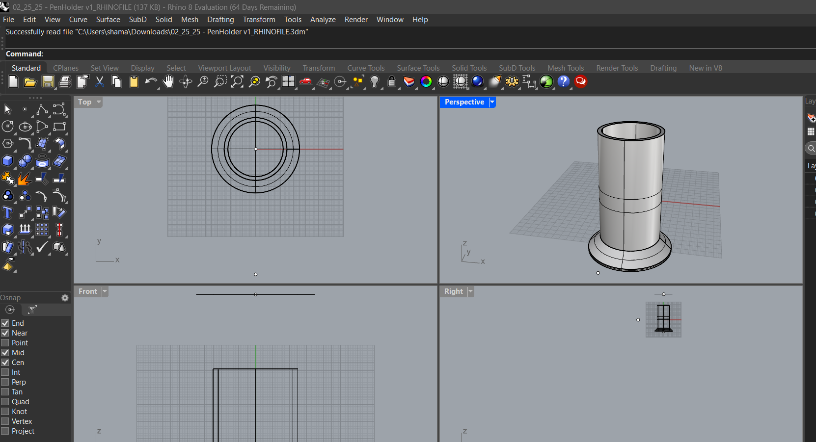
I used the Mesh tool to cover the object and then Showdup to see if there were any duplicate lines which needed to be deleted. My file seemed fine.
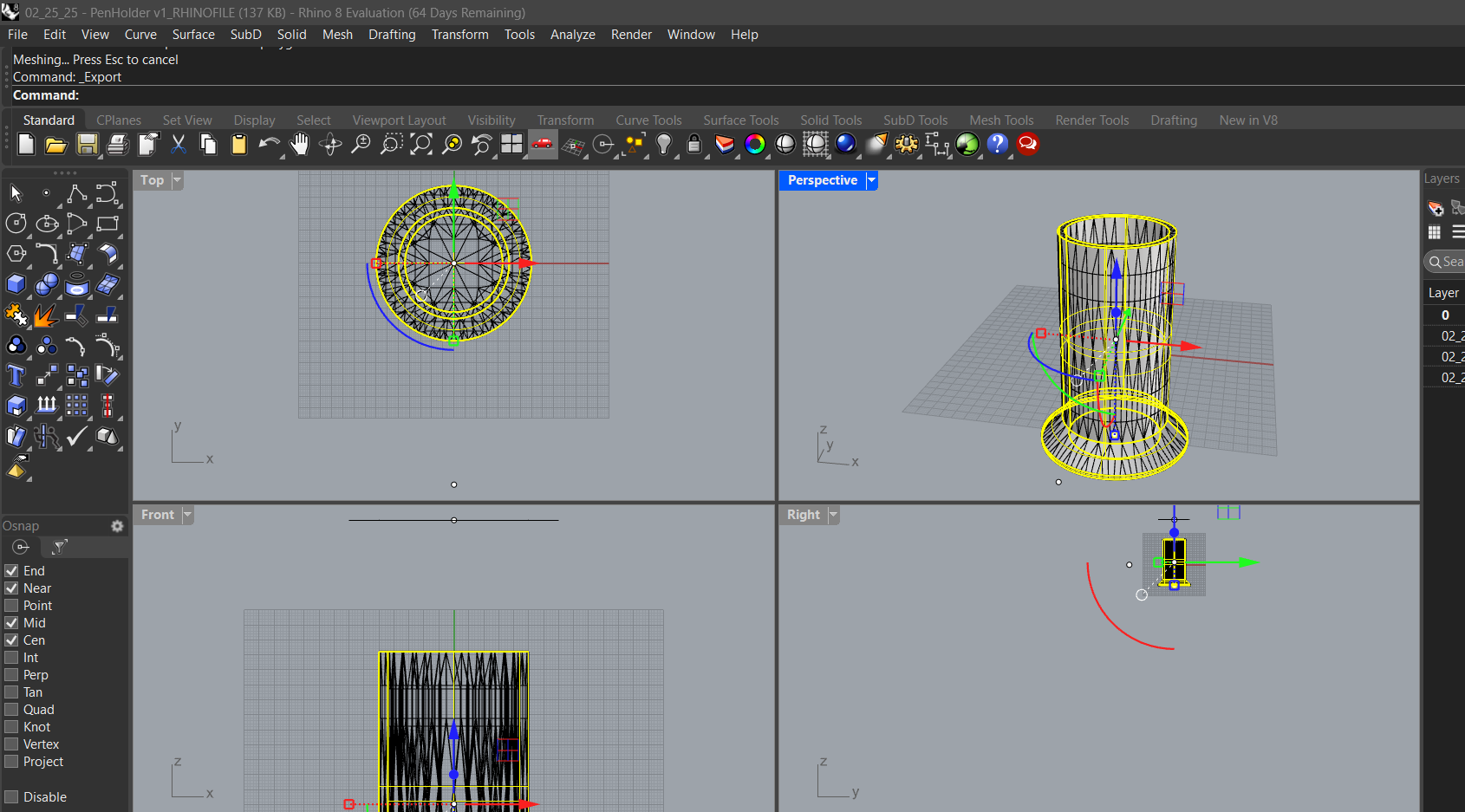
In Rhino 3D I made sure it was in mesh form, by typing mesh. Then showdup to show any duplicate lines which might need to be deleted and would be highlighted in pink if they exist. Next, we need to open the file in Mamba as that is the required Grasshopper plugin to slice the .STL file and generate G-code that the paste printer needs.
Confusion ensued as I tried to insert the Mamba libraries in the Grasshopper plugin library. I tried to get help from chatgpt which erroneously advised me to go to File > Special Folders > Components folder. Finally, Daniel showed me that it had to go into the User Object folder rather than the components folder. I owe a big thank you to Daniel who was trouble shooting many people today. I learned a lot by watching him. While most of us started clicking away like crazy, he would calmly read through various forums and instructions before solving the issue. He kept on reminding all of us as he realised that we needed to slow down. He is a saint! It seems obvious but frustration can ensue when time is short and something technical needs to be done. I keep reminding myself how its much better to read, plan and then execute.
So finally, I opened Mamba, dropped my .STL file in and then sliced to get the G-code. It turned out that Mamba was complicated to setup so we all installed Ultimaker's Cura software which was simple to use.
The story doesn't end there. It wouldn't be any fun if it didn't have a final complication. We also had to download another software called Repetier which would let us print the file.
Preparing the Clay
While this was going on we had to prepare the paste and the paste printer. We took the clay and put it in a bowl, and then we were told to pour in an estimated 5-7% water content per 1kg of clay. So we started slow with about 50 grams and then ended up adding a bit more.
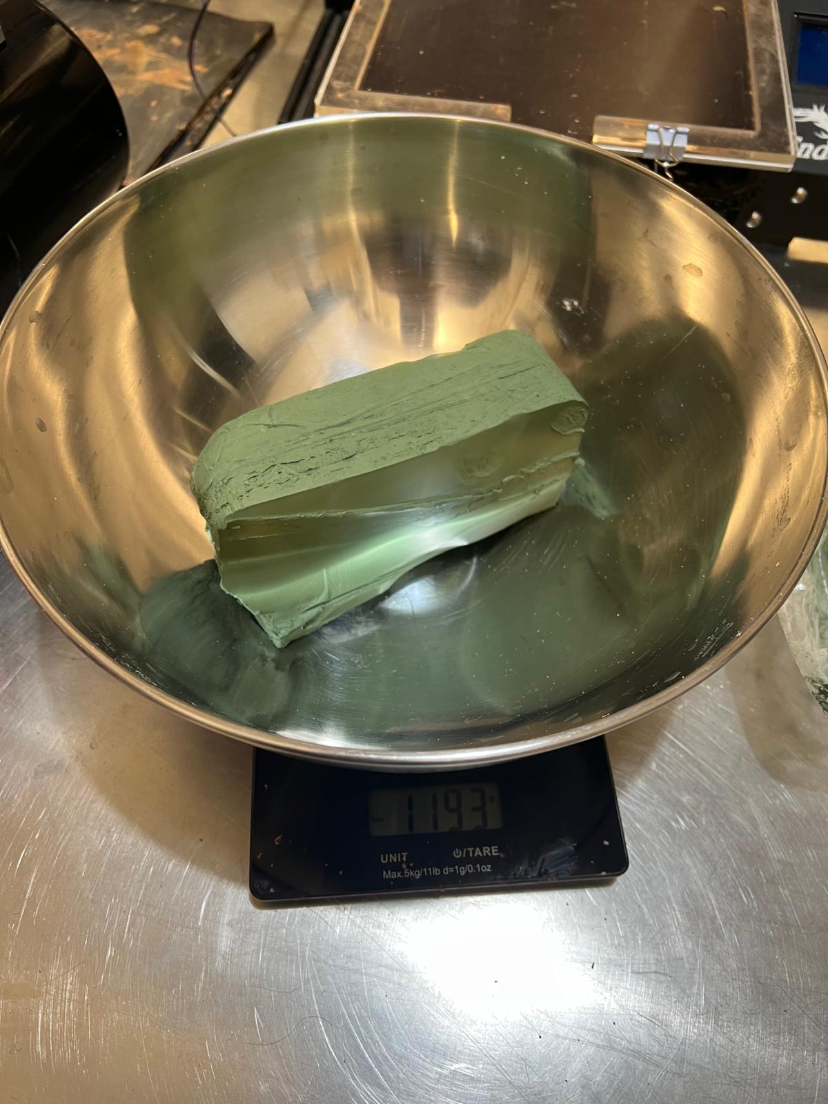
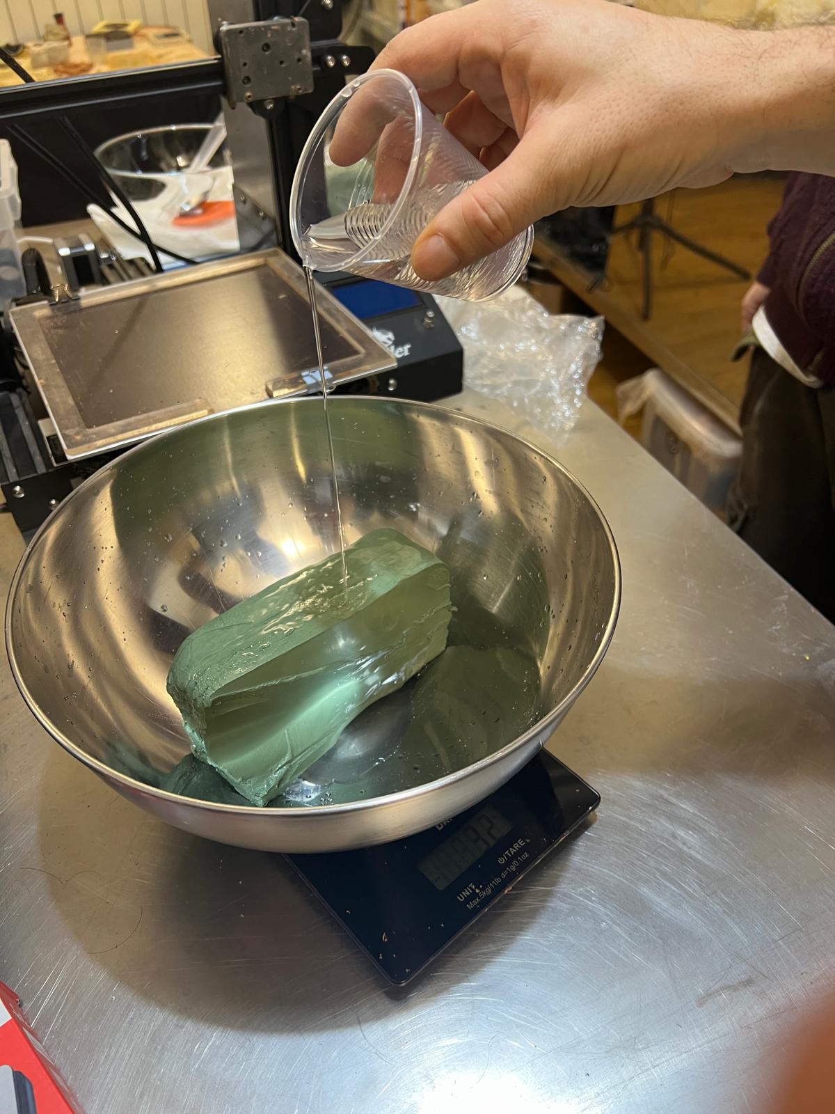
Meanwhile Daniel and I kneaded the clay, squeezing the lumps and bubbles out of until it could be fashioned into a smooth ball and packed into the extrusion canister.
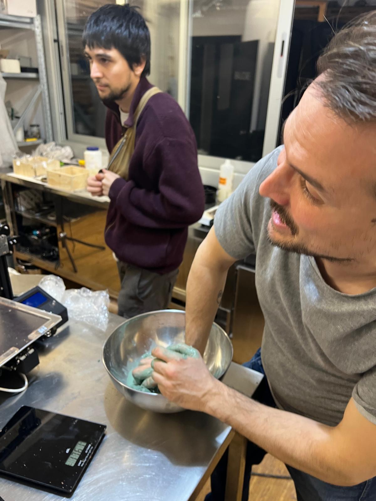
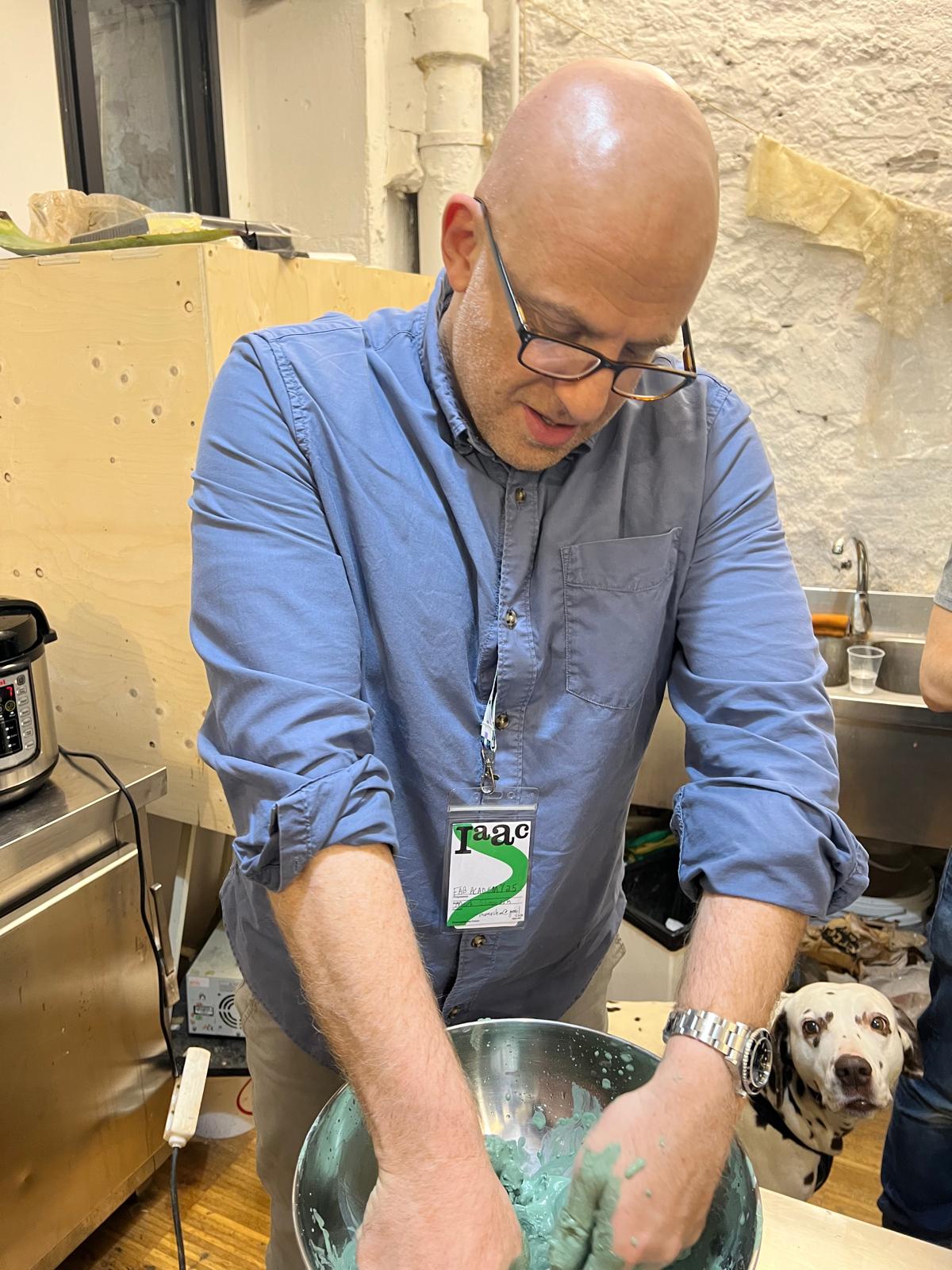
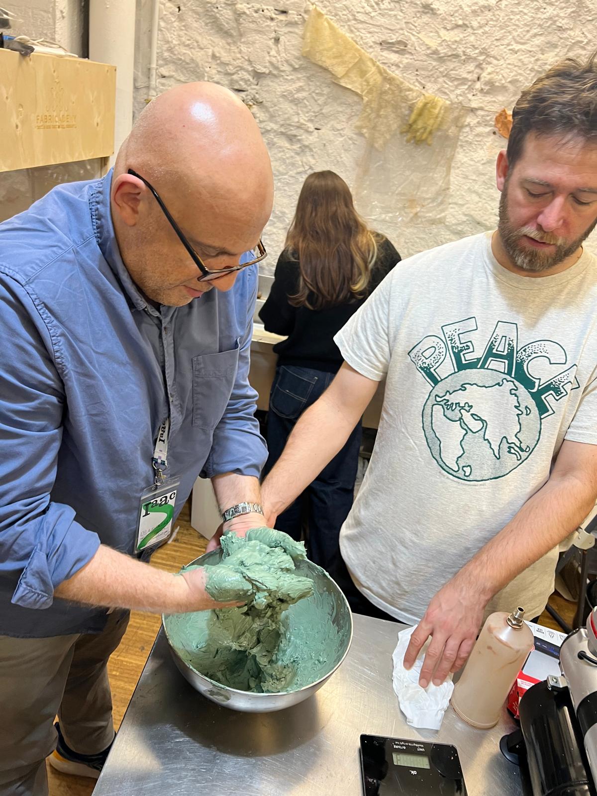
Once we finished, we started packing the clay into a large syringe.
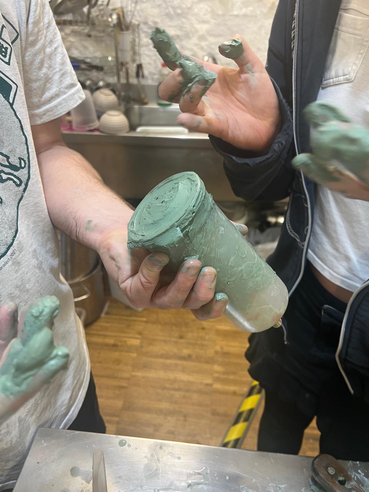
We had to be careful to make sure it was very smooth, no lumps and all the rims were clean and clear.
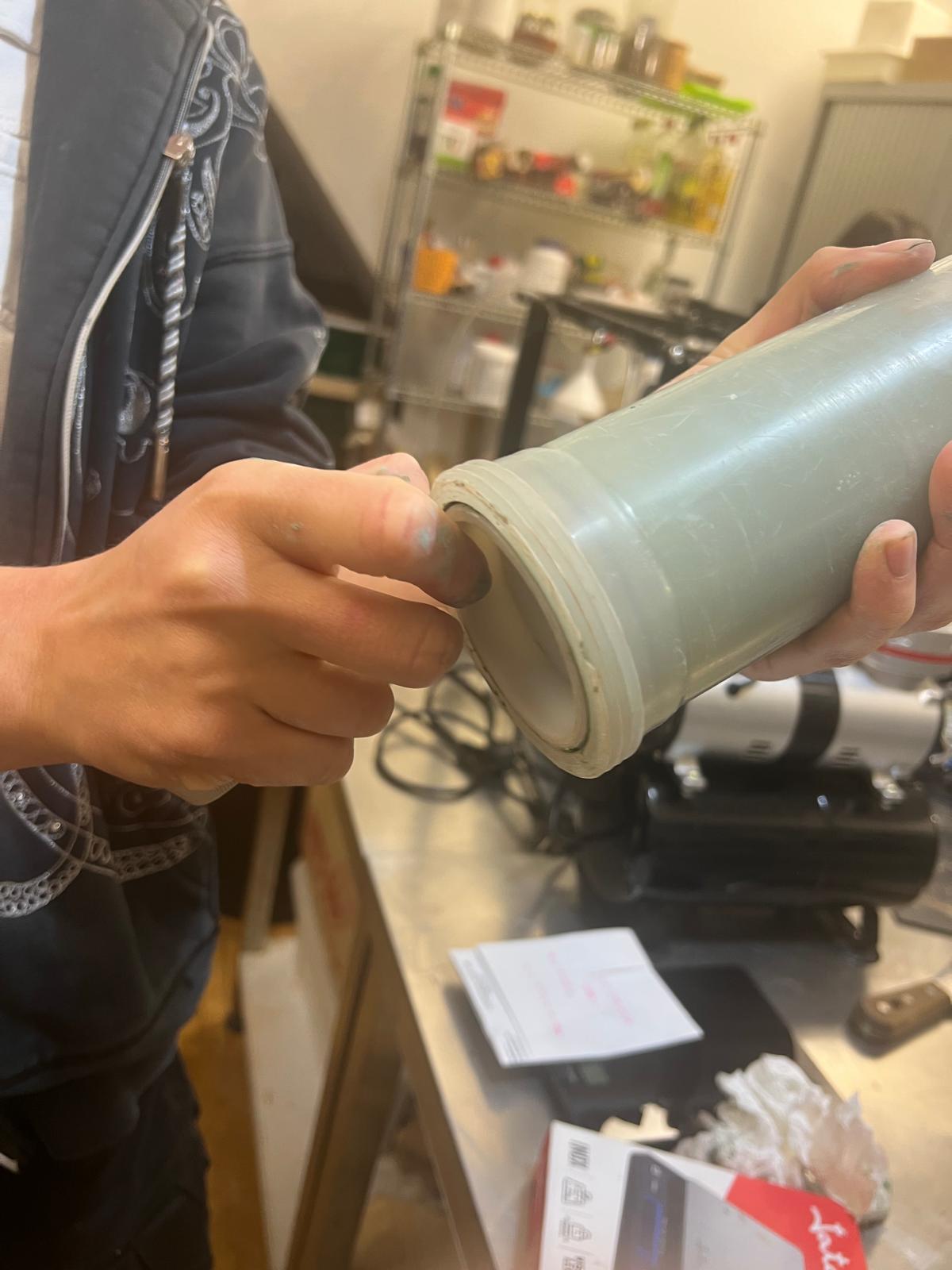
Then after checking all the wire connections on the paste printer were ok
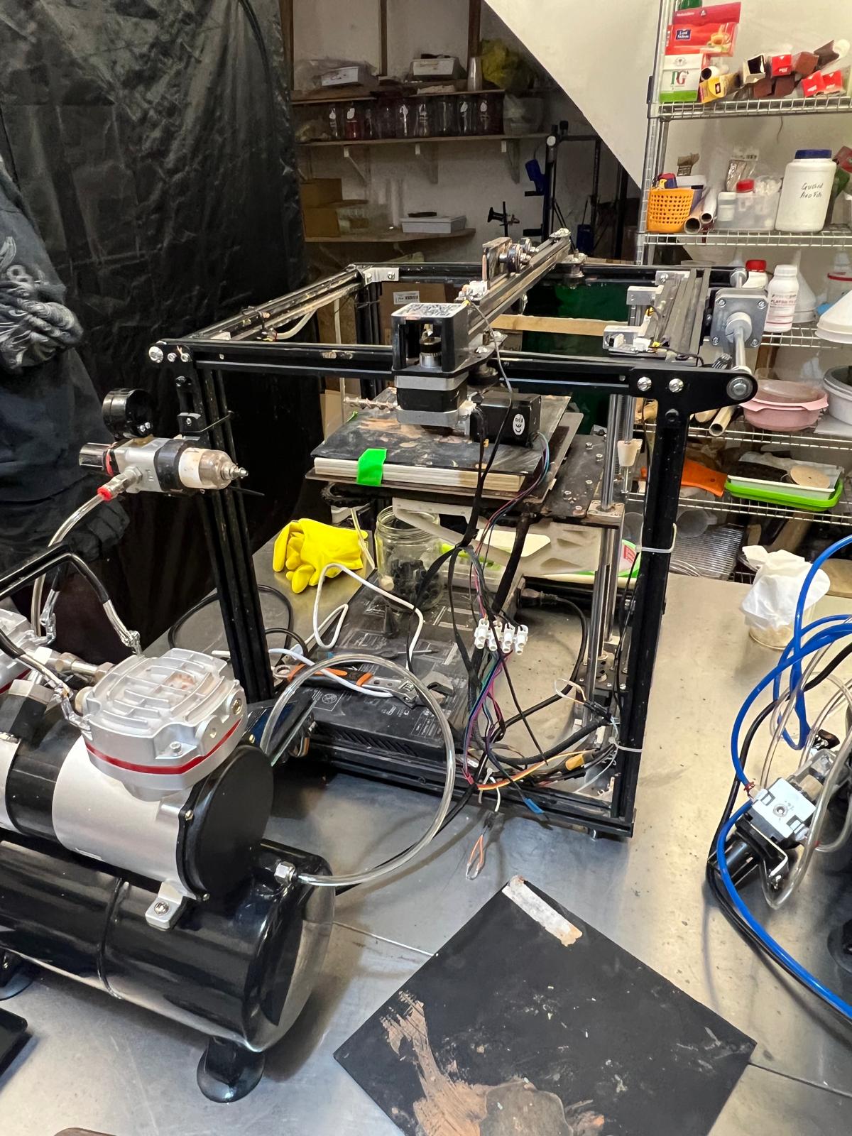
We prepared the extruder and screwed it in.
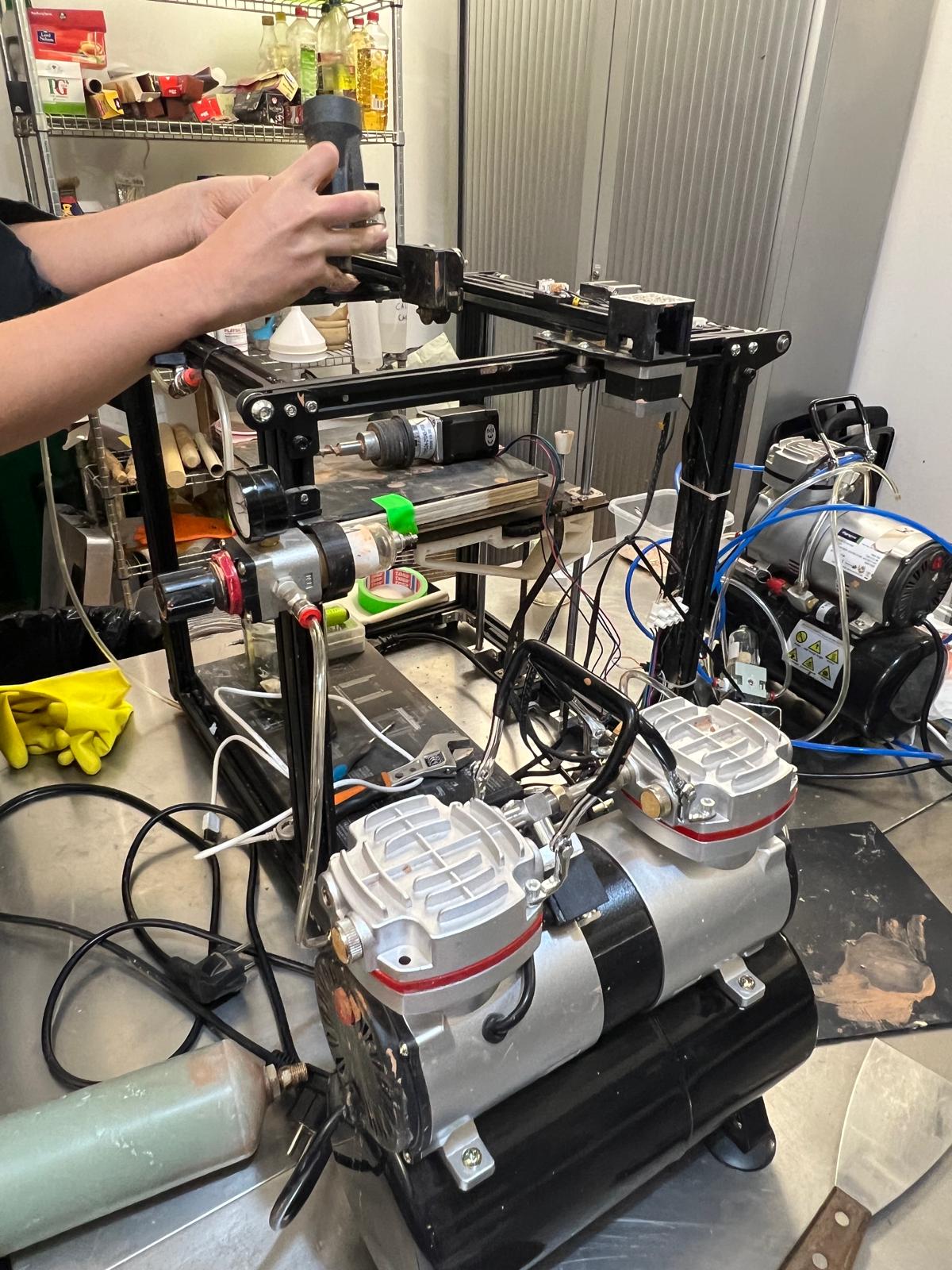
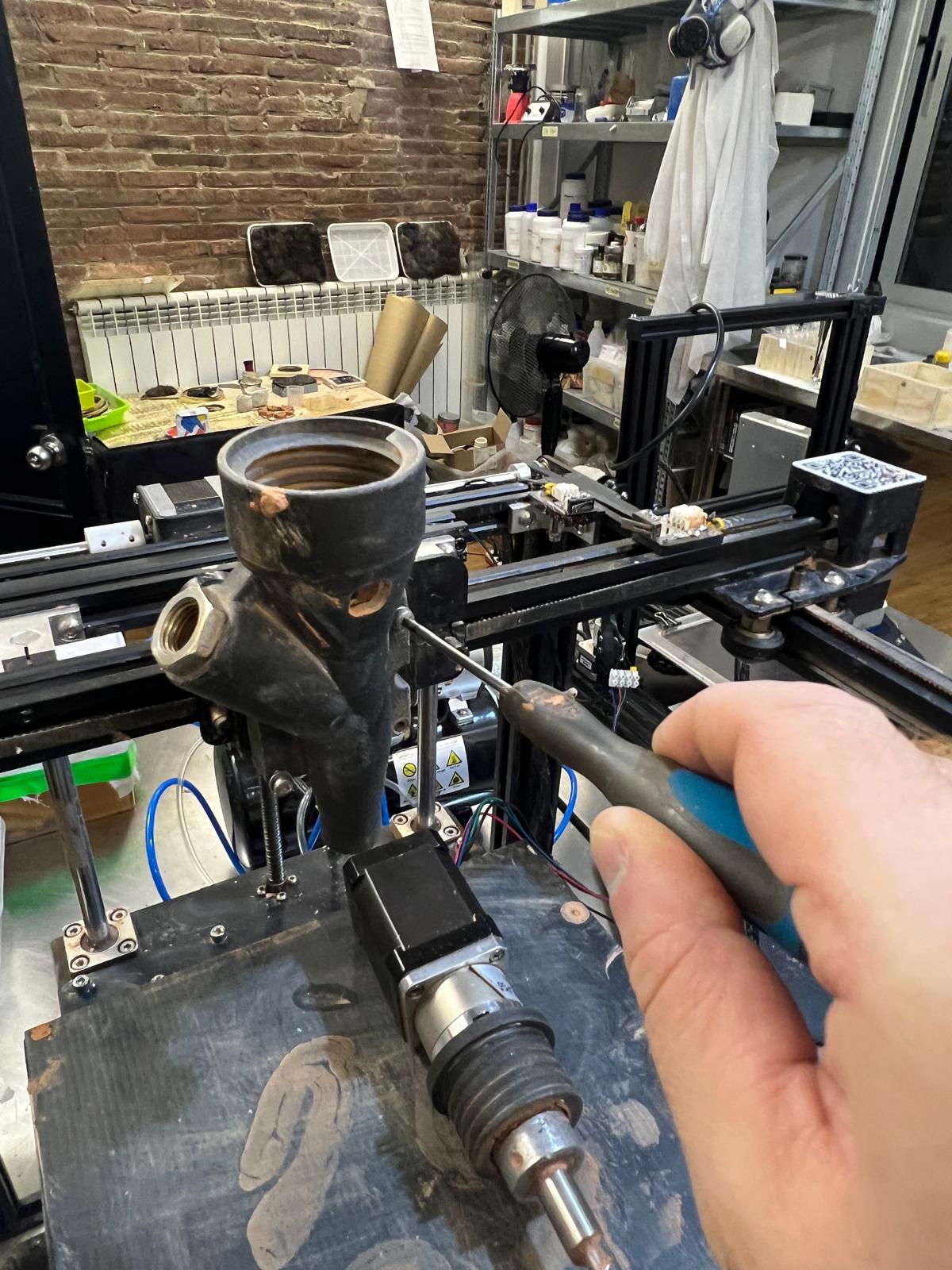
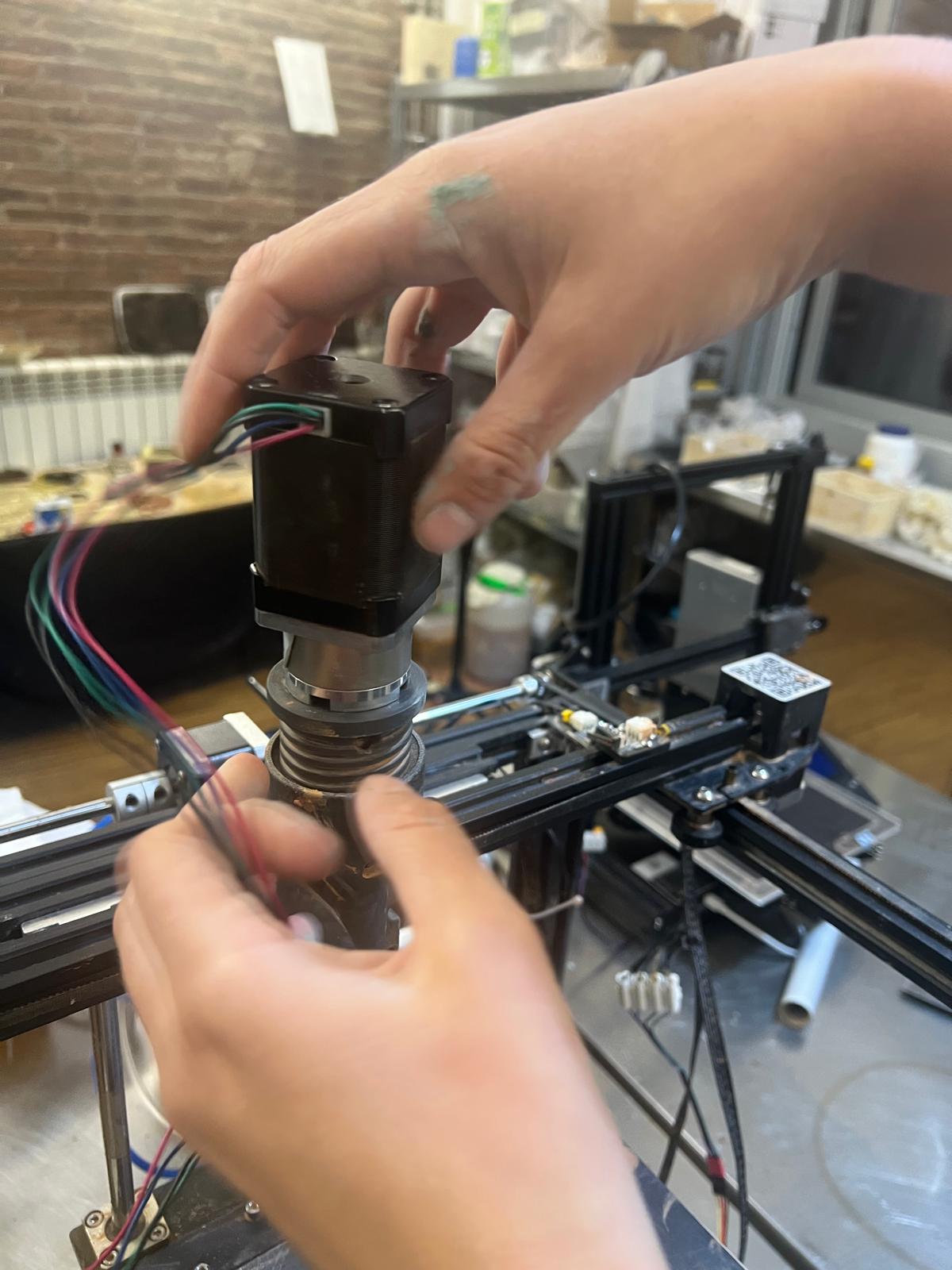
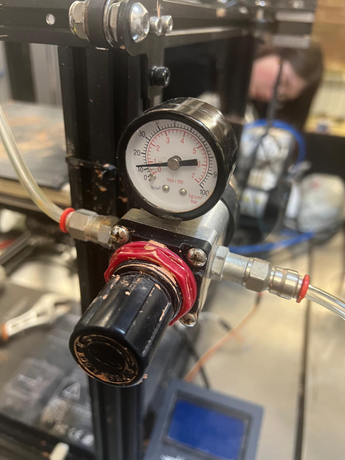
We made sure that the pressure pump was on
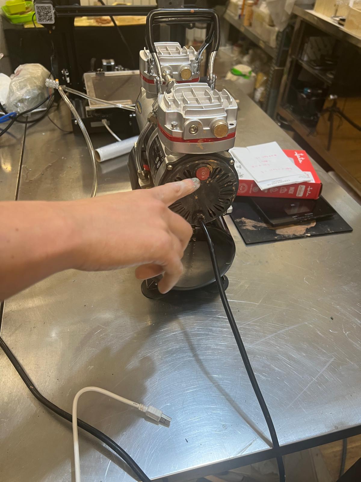
and that the air pressure was set at not more than 2 bars. I am waiting for a chance to print my file so I can update this part of the page.
