Electronics Production
This week is dedicated to Electronic Production, focusing on understanding the materials, processes, and safety measures involved in producing electronic devices, particularly Printed Circuit Boards (PCBs). This involves gaining knowledge about the necessary materials, machinery, software, safety protocols, and a range of electronic components like transistors, capacitors, inductors, microcontrollers, LEDs, and more. I have studied all of these elements. I documented this week's learning in the assignment, which includes information about the machines, the necessary tools for their operation, and the production of PCBs. Task involved in this week is:
Group Assignment:
characterize the design rules for our in-house PCB production process by doing precision test.
visit our group assignment page click here
Individual Assignment:
Creating and Testing a Microcontroller Development Board
PCB fabrication:
PCB having the full meaning Printed Circuit Board. PCB is used for connection for the circuit. It also known as Printed
Wiring Board. It is a boards that electronic components are placed on. It's like the foundation of electronic devices.
PCBs can be designed as single-sided, double-sided, or multilayer boards. In this assignment, I utilized a single-sided printed circuit board (PCB).
Reference link
I refer to the work completed by previous students to gather details for my reference.
Reference
Single Layer PCB
Single sided PCB also called sigle-sided boards. In this type of pcb we solder components on one side and they have conductor pattern on opposite side of the board. Its having only one layer of conductive material, usually copper. A single-layer board is made up of a substrate layer means layer of base material, a conductive metal layer and then a protective solder mask and silk-screen.Reference link
Etching:
Etching is a classical technique used to create designs on metal surfaces by employing strong acids or chemicals. This method is prevalent in printmaking and continues to find applications in modern technologies, such as circuit board fabrication. In the traditional etching process, a metal plate is first coated with a protective layer. The artist then selectively scratches away this layer to reveal the metal underneath, outlining the desired design. The plate is subsequently immersed in acid, which etches into the exposed areas of the metal, forming the intended patterns. Once the protective coating is removed, ink is applied to the plate and carefully wiped off, leaving ink only in the etched lines. By pressing the plate onto paper, the ink is transferred, producing a print. This etching technique can be repeated multiple times until the plate starts to wear, and artists have the option to modify or enhance their designs by reapplying the protective layer and etching anew. Additionally, etching can be combined with other methods, such as engraving or aquatint, to achieve more intricate artworks. Reference Link
Chemical required during etching process:
Acetic acid/White Vinegar (CH3COOH )/(CH3CO2H or C2H4O2)
Citric acid (C6H8O7)
Hydrochloric acid / Muriatic acid (HCl)
Hydrogen Peroxide (H2O2)
Sodium chloride (NaCl)
Copper sulfate (CuSO4)
Milling
PCB milling involves the process of shaping a flat piece of material into a circuit board by removing excess material. Rather than using a knife, this method employs a specialized machine that eliminates copper in designated areas according to a digital design. This design guides the machine on where to cut away the copper to form the necessary electrical pathways and components for the circuit board.
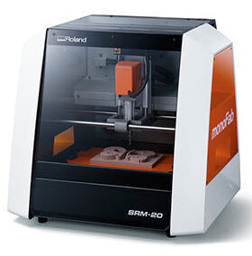
We used Roland Monofab SRM-20 machine for milling.
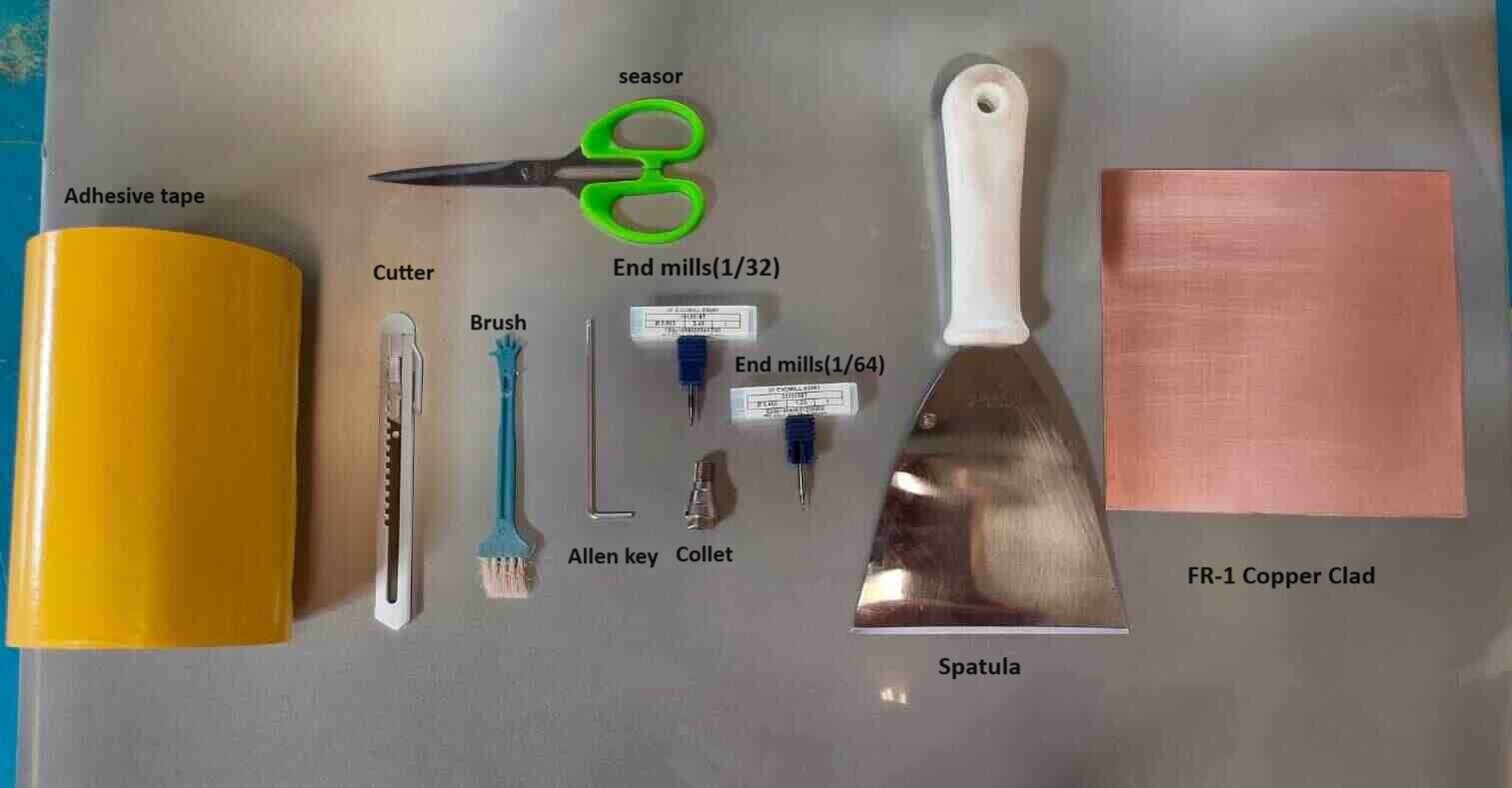
Material and tools required for milling are:
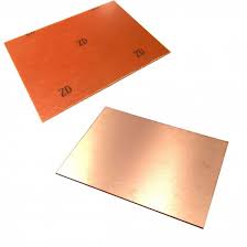
FR-1 Copper Clad
Adhesive tape
Allen Key
End mills(1/64,1/32)
Spatula
Dusting brush
Scruber
vaccum cleaner
seasor
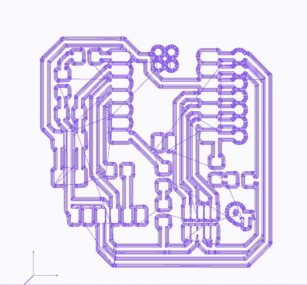
As part of this week's assignment, I have to mill a PCB (Printed Circuit Board). For this assignment we have ready files name quentorres to accomplish this, I have generated tool paths for tracing, cutting, and drilling the PCB. Detailed process for milling PCB steps are below :
For this assignment we have the ready file for circuit diagram which we have to mill on PCB with SRM-20 milling machine. I downloaded this file from our fab acedemy webside. This file is in png file format.And for milling we require rml format.So here first task is to convert these three trace, cut and drill png files into rml file format.
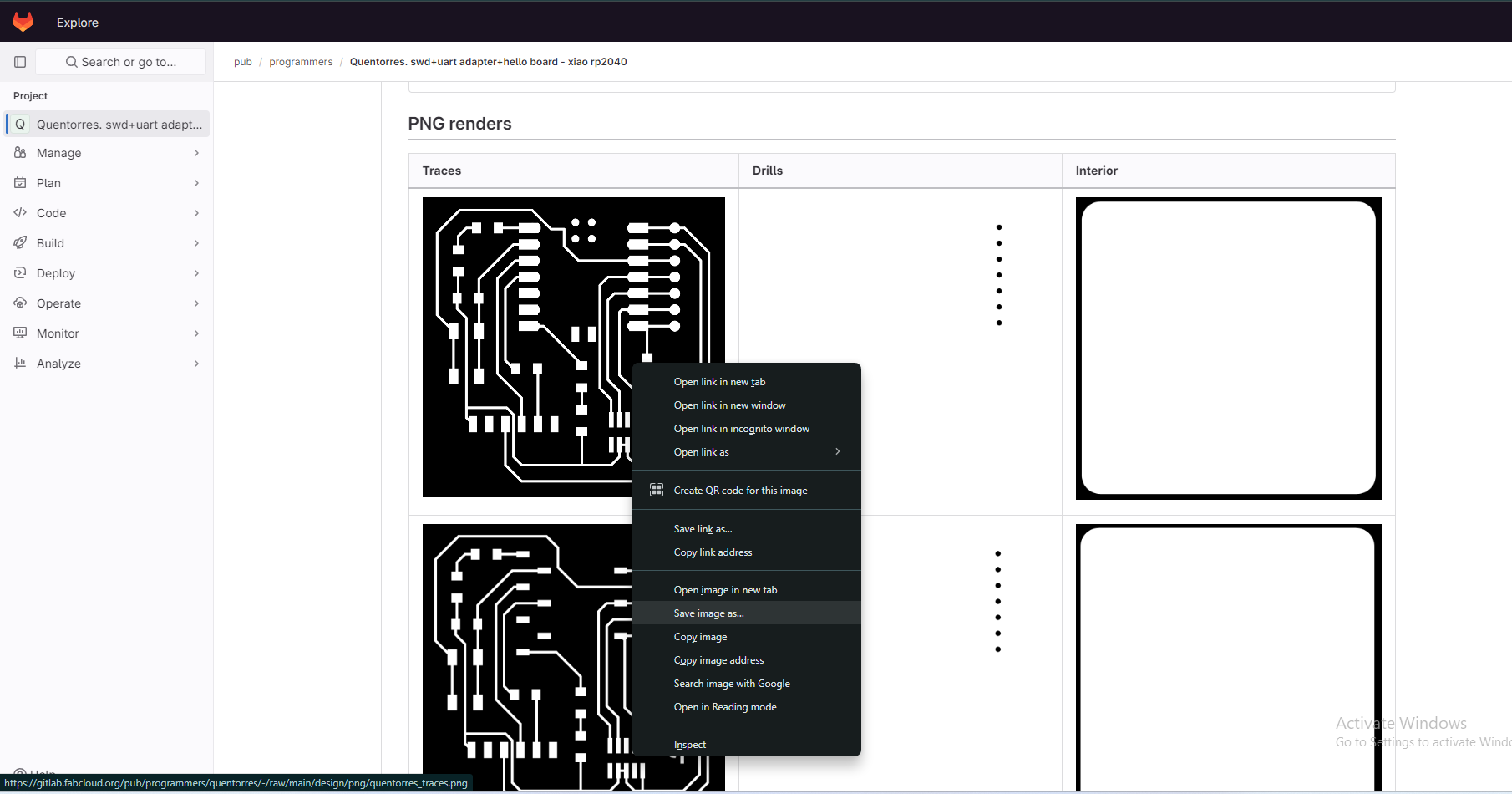
First,I have start with production of Microcontroller development board,Begin by downloading the trace,drill and cut file in PNG format from the Mods CE website.Import the downloaded file into our production machine.
Click link on Fab acedemy schedule for electronic production week.
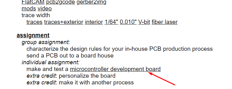
Download trace, drill and cut png file for Quentorres
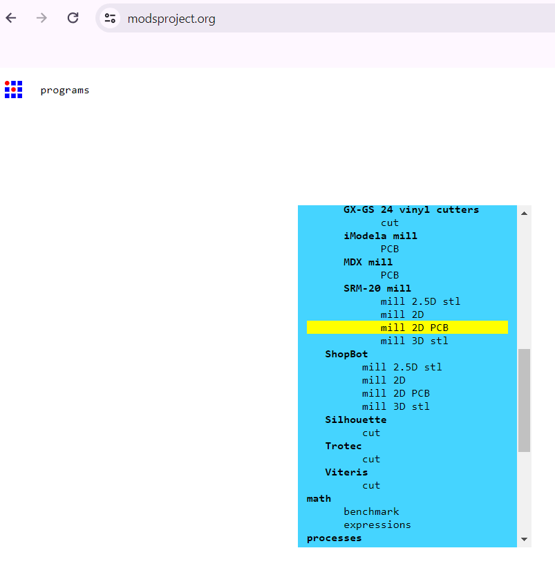
Search for "mods ce" on google.

Program Selection and Configuration
Access the "mods CE" website, a program for designing PCBs.When you right-click on an open site, you'll see four options:
1.Modules
2.Programs
3.Edit
4.Options
In programs again for options:
Open program for file
Open program
Save program to file
Save HTML page

I choose the "Open Program" option and select the SRM-20 mill machine, specifying "mill 2D PCB"
Choose open program and select "mill 2D PCB"
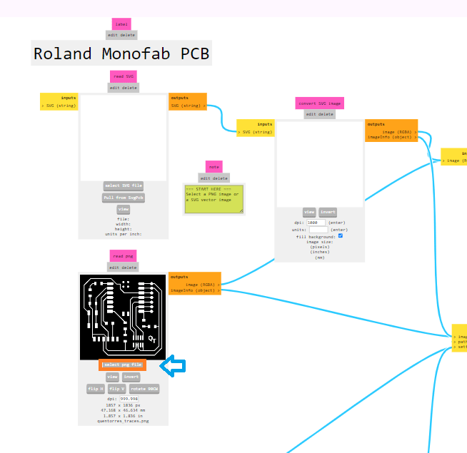
Import the downloaded png file
Import the downloaded png file into the program first I selected trace file for quentorres.
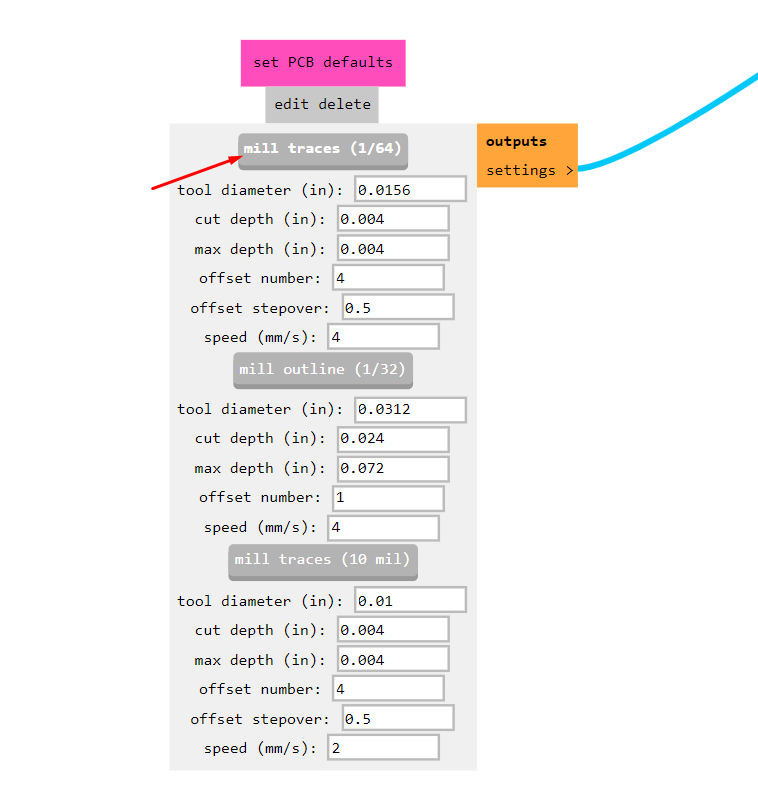
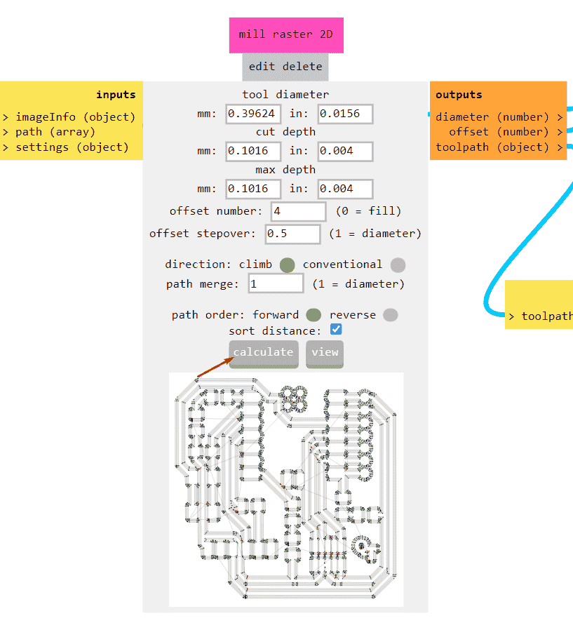
Set the PCB defaults
I choose 1/64 bit for trace file milling. Here is important to select the end mill I have selected 1/64 end mill for trace which is important to set the machine tool.
Configure parameters such as x, y, z
Configure parameters such as x, y, z distances from origin, speed, and job height for roland SRM machine. I take job height at z axis is 12mm and distance from origin for x,y,z are zero.
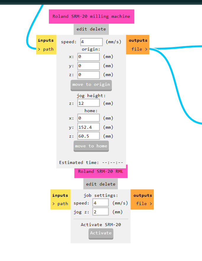
File Saving and Conversion
Disable the WebUSB option and enable the save file option.
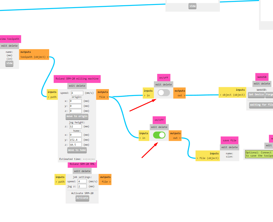
Save the file, which will generate an RML file necessary for the PCB milling machine.as we saved our file all selection goes to mill raster 2D then simply calculate it.
It gives us RML file which is input for our PCB milling machine.
Roland Monofab PCB Milling Machine Setup:
Switch on the SRM-20 machine and connect it with pc
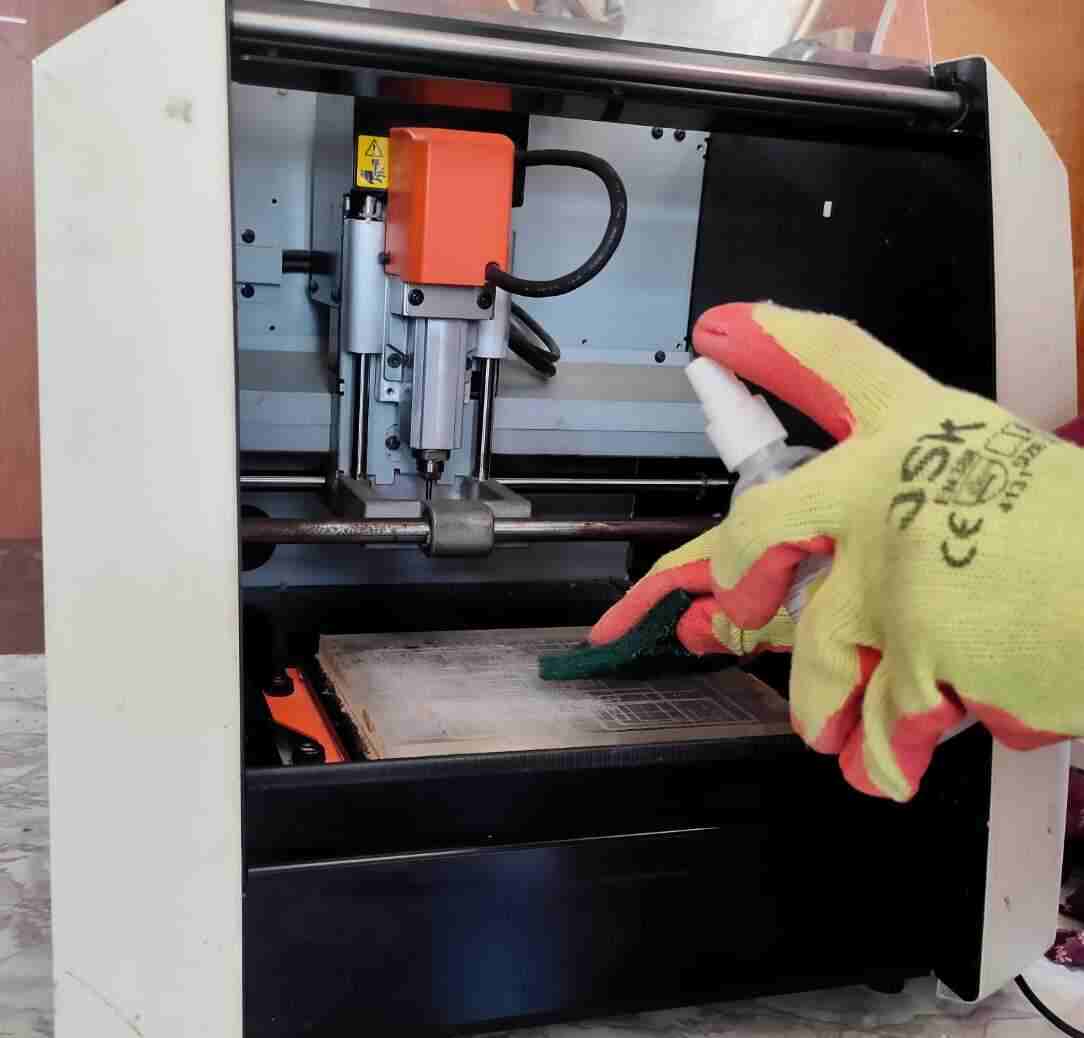
In our lab vigyan ashram we have Roland Monofab PCB milling machine. we first Cleaned the Roland Monofab PCB milling machine thoroughly before use and then by switching on power button on machine I connected the machine with software on pc with connector.
Mount the copper clad on machine bed
Clean the bed
Apply double-sided adhesive tape carefully to the backside of the copper clad, ensuring no bubbles and uniform application.
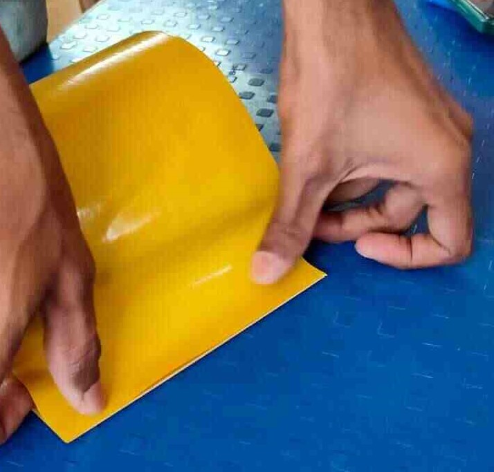
Then remove the outer paper of adhesive tape.
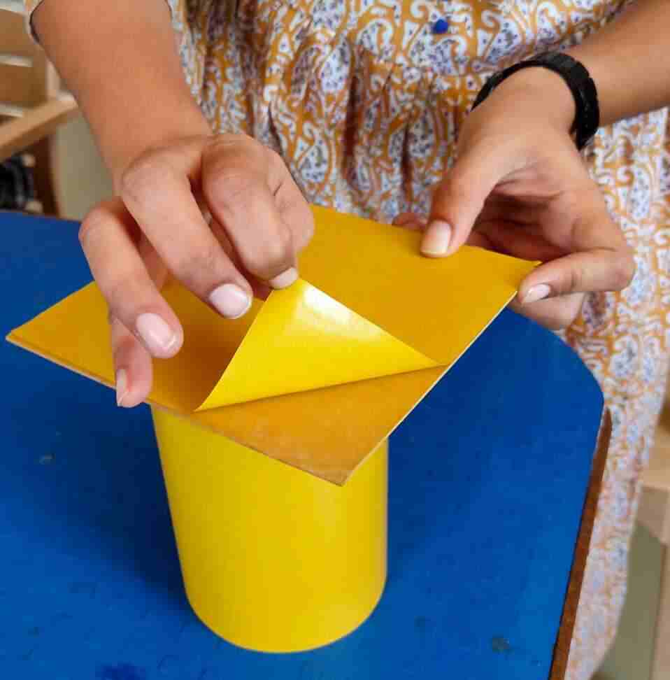
Paste that copper clad on machine bed.
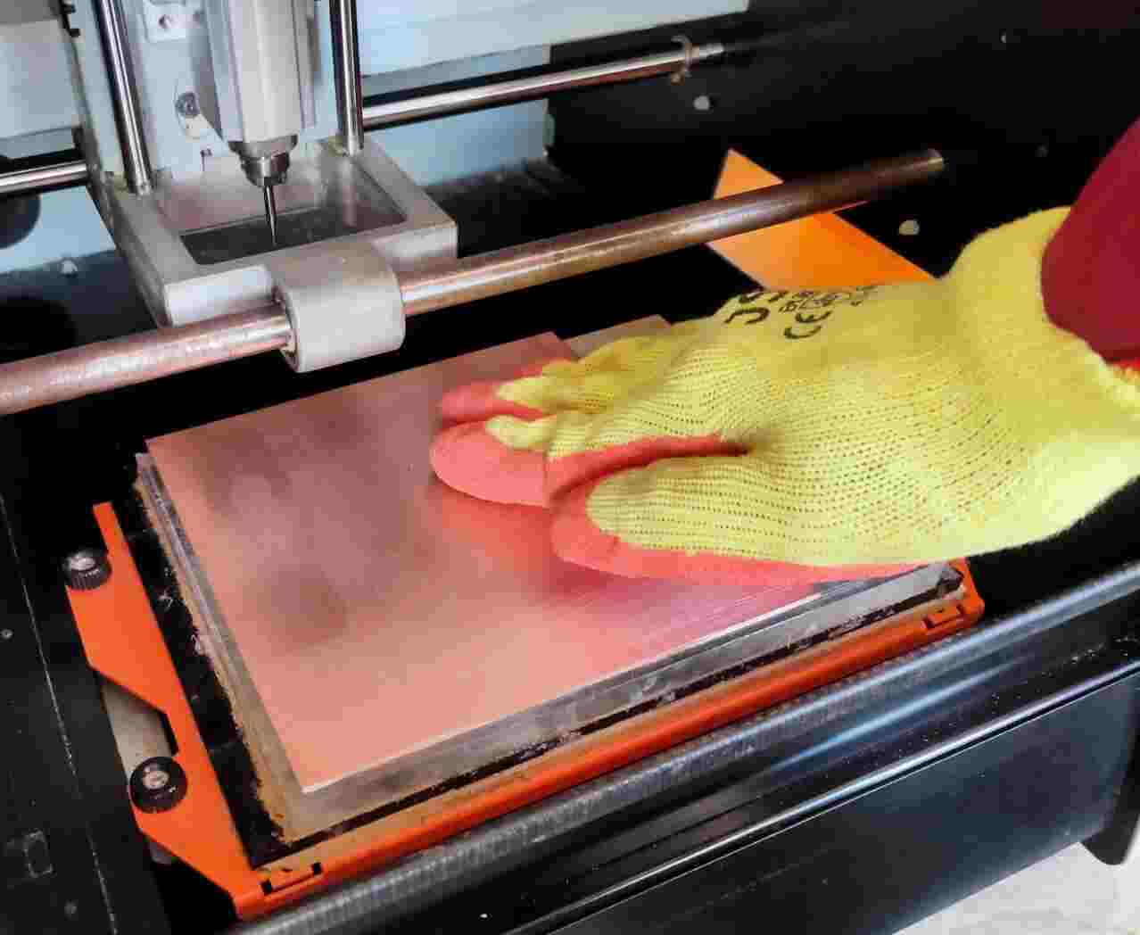
Then start the production process...
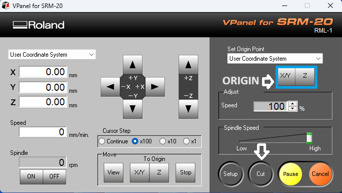
Open the "V panel" software.
First I connected the PCB mill machine with our Computer.We have opened v panel software for our machine. Here is the button for movement of bed in x and y in left or right direction and movement of head in z direction for up or down.
Select the milling area.
Then we have to set the head on which our drill bit is fixed and machine bed position according to space on pcb for milling our circuit or mill our trace or rml files. Then we have to set end mill x,y,and z position and then with gravity we have to touch the end mill to Copper clad then the machine is ready for printing
make X, Y and Z origin.
Origine xy and z by click button shown in above image.
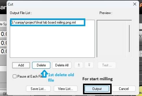
Upload the rml file
Click on cut button as shown in image it opens the file then new file, this most imortant that to delete the previous file and select new one.
Click Output button
I have first selected downloaded trace file start the milling process.By clicking output button milling for uploaded file is started.
Similarly, next I given file for drill and then cut
For trace, drill and cut have the same procesure. After completion all process for miiling the quantorres I moved towards soldering.
Soldering
Soldering is a process of joining two metal surfaces together using a filler metal called solder. The soldering process involves heating the surfaces to be joined and melting the solder, which is then allowed to cool and solidify, creating a strong and durable joint.Read More
In my quanterroes board I used RP2040 microcontroller board. then by refering document on fab acedemy site I found other componenets from my inventory like led, register, push button.
My Quanterrous after soldering
.jpg)
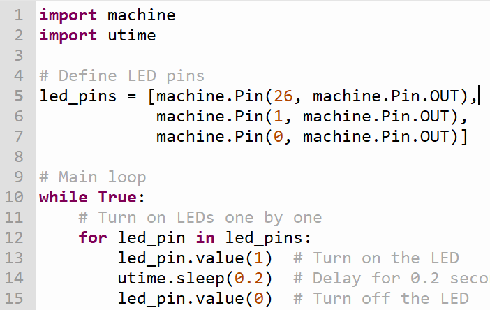
Programming
I have done programming for my quantorres board..
Key Learning
In this assignment I learn about the design files for traces, drill and cut.
Also I learnt about png file format and rml files.
Also learn about milling the quantorres board. For that I understand about machine work and software for convert file.
I practice in this assignment for good soldering practices.