Computer-controlled Machining
This assignment is about understanding Computer Controlled Machining. In Computer Controlled Machining, there are group and individual assignments. In this assignment, the task is to create something substantial (something big) using a wood router machine. Therefore, it is crucial to understand the machine's specifications and its operation.
In the group assignment, our primary focus is to conduct trial and error experiments to familiarize ourselves with the machine. Safety is paramount during these experiments as there is a risk of tool breakage and potential injury. Hence, safety precautions are of utmost importance.All observations and learnings are documented below in this assignment
Why This Assignment:
To Create, fabricate, and construct something substantial on the scale of meters.
Don't use screws, nails, or glue.
Make job by using curved lines and shapes..
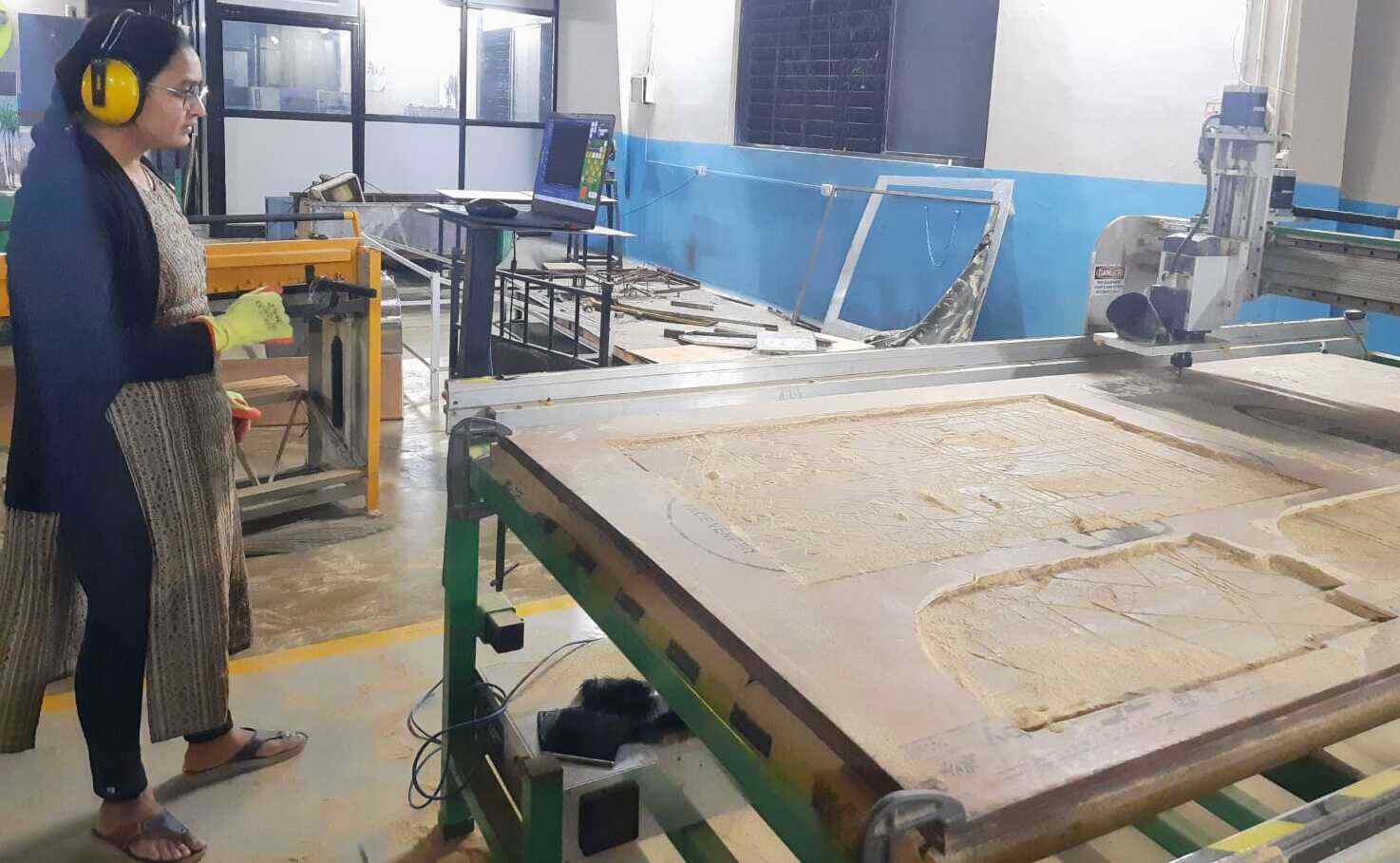
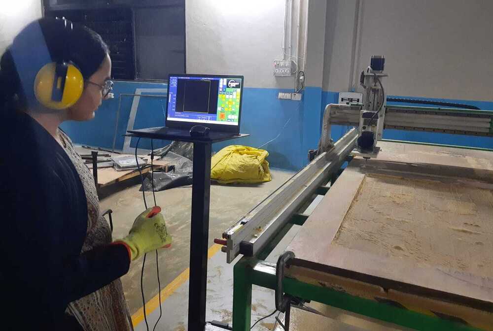
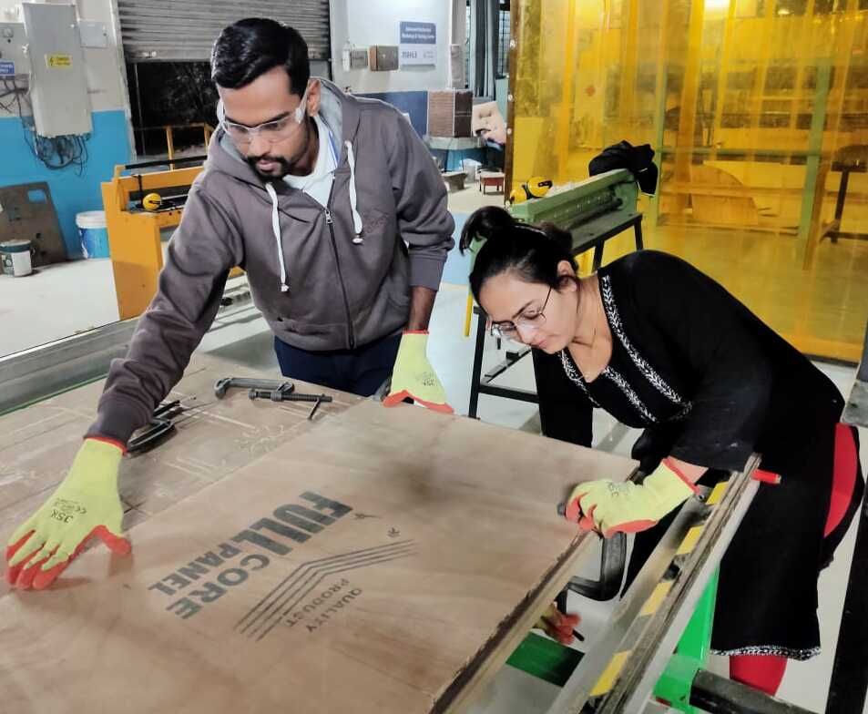
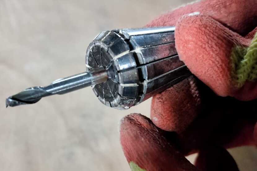
My Super shots for this week
Computer Controlled Machining
Computer-controlled machining is an automated manufacturing process that utilizes embedded computer software to precisely control and manipulate machine tools.Computer-controlled machines come in various types, each designed for specific purposes and industries.
1. CNC Machines (Computer Numerical Control):
CNC stands for Computerised Numerical Control. It's a system that uses electronic digital computers to control machines like routers, grinders, laser cutters, and more. Instead of manually operating these machines, CNC automates the process. However, a user still needs to oversee and manage the CNC machine.
A computer translates designs from Computer Aided Design (CAD) software into numerical instructions. These instructions, often coordinates on a graph, guide the movement of the cutting tool. This allows for precise cutting, shaping, and designing of materials like wood, aluminum, plastic, steel, and foam.
CNC Milling Machines:
Used for cutting and drilling operations on solid materials like metal, wood, or plastic.
CNC Lathes:
Utilized for shaping cylindrical parts by rotating the material while a cutting tool moves along it.
CNC Routers:
Primarily used for cutting, carving, and engraving materials such as wood, plastic, and metal.
CNC Plasma Cutters:
Employed for cutting through electrically conductive materials using a plasma torch.
2. 3D Printers:
Fused Deposition Modeling (FDM) Printers:
Create objects by depositing layers of molten material, usually plastic.
Stereolithography (SLA) Printers:
Use UV lasers to solidify liquid resin layer by layer to form intricate 3D shapes.
Selective Laser Sintering (SLS) Printers:
Employ lasers to fuse powdered materials (plastic, metal, ceramic) into solid objects.
3. Automated Assembly Machines:
Used in manufacturing to automate the assembly process of products such as electronics, automobiles, and consumer goods.
4. Robotics:
Industrial Robots:
Automated machines programmed to perform tasks like welding, painting, assembly, and material handling in manufacturing environments.
Collaborative Robots (Cobots):
Designed to work alongside humans safely, often used in tasks requiring dexterity and flexibility.
5. Computer-Controlled Cutting Machines:
Laser Cutters:
Utilize a high-powered laser beam to cut through materials like metal, plastic, wood, fabric, and glass with precision.
Waterjet Cutters:
Use a high-pressure jet of water mixed with an abrasive substance to cut through various materials.
6. Computer-Controlled Embroidery Machines:
Used in the textile industry for automated embroidery and stitching designs onto fabric or garments.
7.Computer-Controlled Routing Machines:
It is utilized for cutting, shaping, and engraving a variety of materials, including wood, plastic, and foam.
8. Computer-Controlled Sewing Machines:
Employed in garment manufacturing and textile industries for automated sewing operations.
This assignment is on CNC Router
CNC Router
A CNC router is a kind of computer-controlled device designed for milling, drilling and cutting materials. CNC routers are similar to milling machines,nearly identical functions. Their primary purposes include cut, engrave and carve objects from a raw material, effectively substituting for traditional handheld routers.For more information about CNC Router Please Refer link
Group Assgnment
CNC routers are like fancy robotic tools used for cutting and shaping materials like wood or metal. They come in different sizes and shapes, with some having just one direction they can move in, while others can move in multiple directions. They can also change their tools to do different jobs.They are controlled by computers. So, we can give them a design on the computer, and they'll follow it exactly. This design is called a CAD file. We used specialized software called Vcarve to convert the CAD file into a series of instructions known as a tool path, which the machine can interpret and execute. These tool path tell the machine how to move its tools to make the design actually. we can either make these tool path ourself for simple jobs or let the software do it automatically for more complex tasks.
We have forest CNC machine in our fablab.We used flat end mill with diameter 6 mm.My Group Assignment link Click Here
Individual Assignment
Routing is a common method used in woodworking, sign making, molding, and other industries. It's great for making precise cuts repeatedly. CNC routers, which are computer-controlled machines, can work with various materials like wood, metal, stone, plastics, and more. Some have dust collection systems to manage waste.Using computer-controlled routers reduces production time and errors by creating consistent objects, as long as external factors are controlled. Modern CNC routers come in different sizes, including desktop versions that fit on tables. Improved software, like CAD/CAM programs, makes it easier to operate these machines. Specialized programs can create models and generate design codes, making CNC routers useful for amateurs, furniture makers, and designers without advanced skills in carving or woodworking.The step by step process to operate this machine is given below.
Step 1: Design
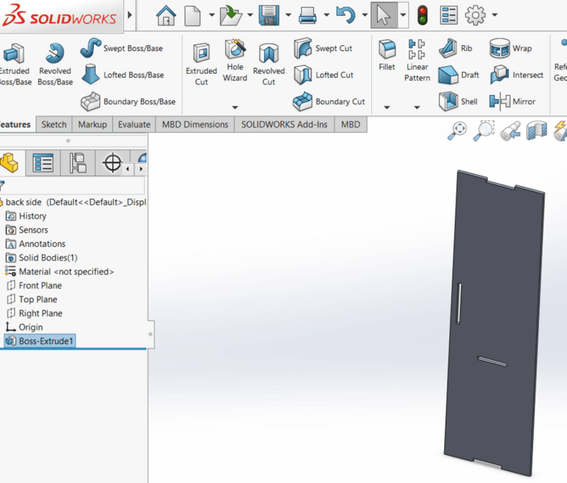
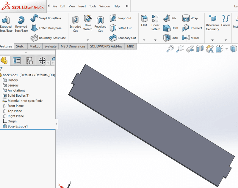
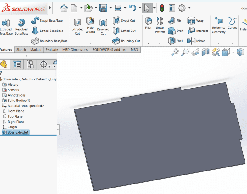
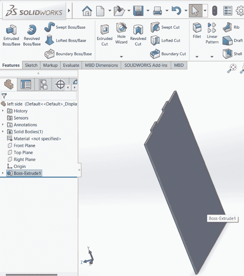
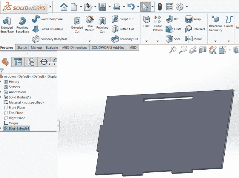
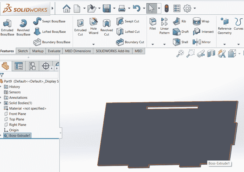
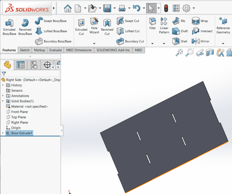
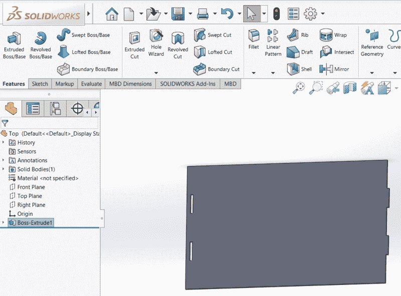
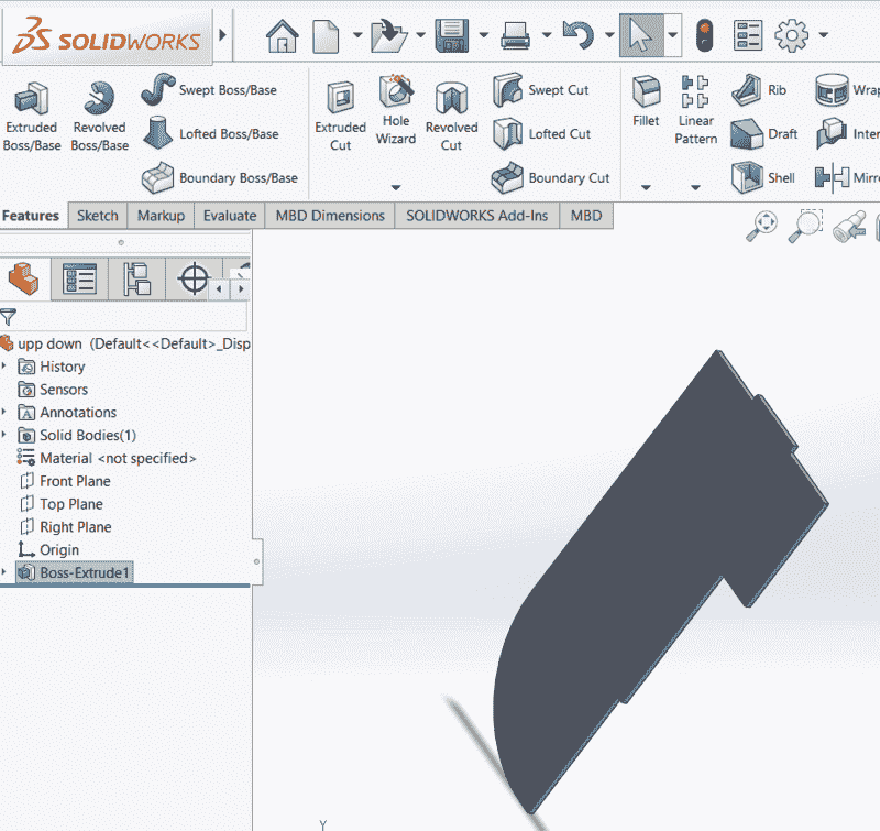
First I designed object in solidwork. This assignment objective is to make something big and do not use nails, fasteners for assembly of our object and also includes curved surface. So I decided to make table.
Step 2: Tool Path Generation
1. Open your design file in Vcarve Software.
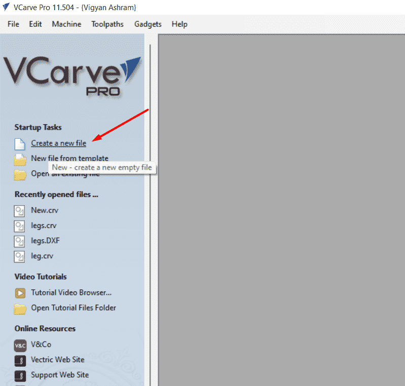
We use "VCarve" software with the Forest CNC machine to create the necessary toolpath for operations. Open Vcarve software and select create new file for tool path generation.
2. Set The Dimensions According to our Design
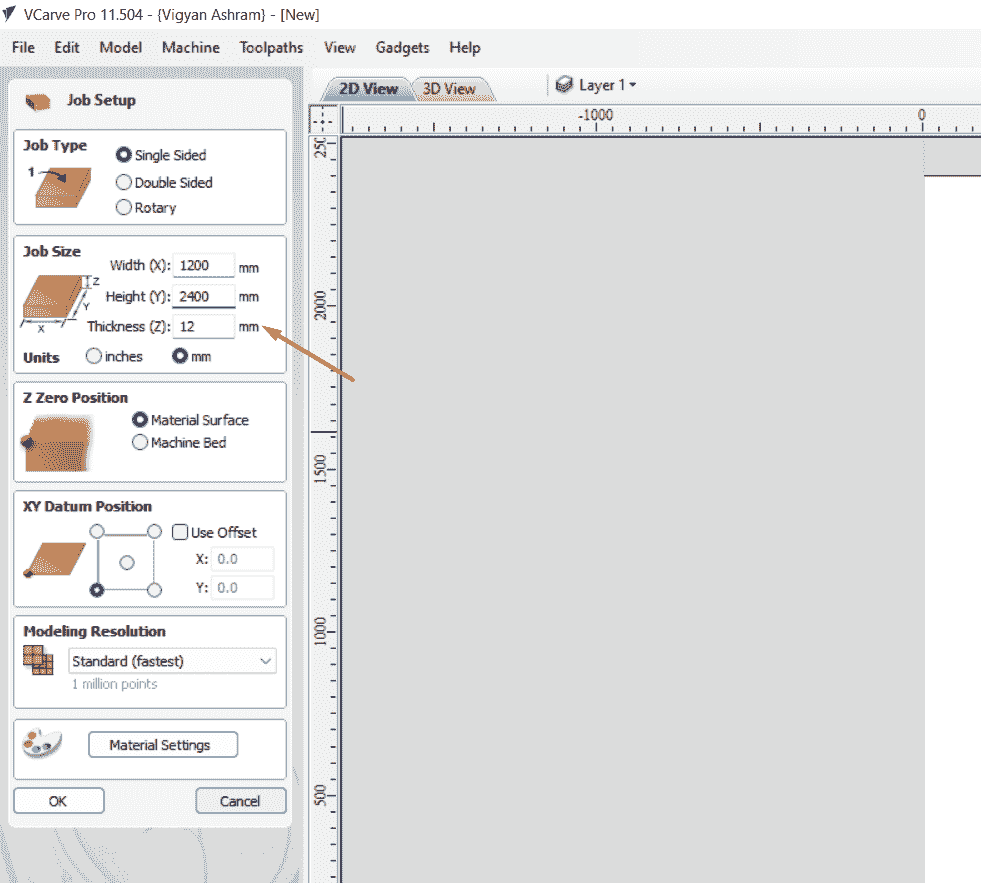
After selecting create new file you will see interface like in picture.and then set dimensions here like Job size, Job type, Z zero position, XY detum position, Modelling resolution and material setting here and click Ok button.
3. Load dxf design file
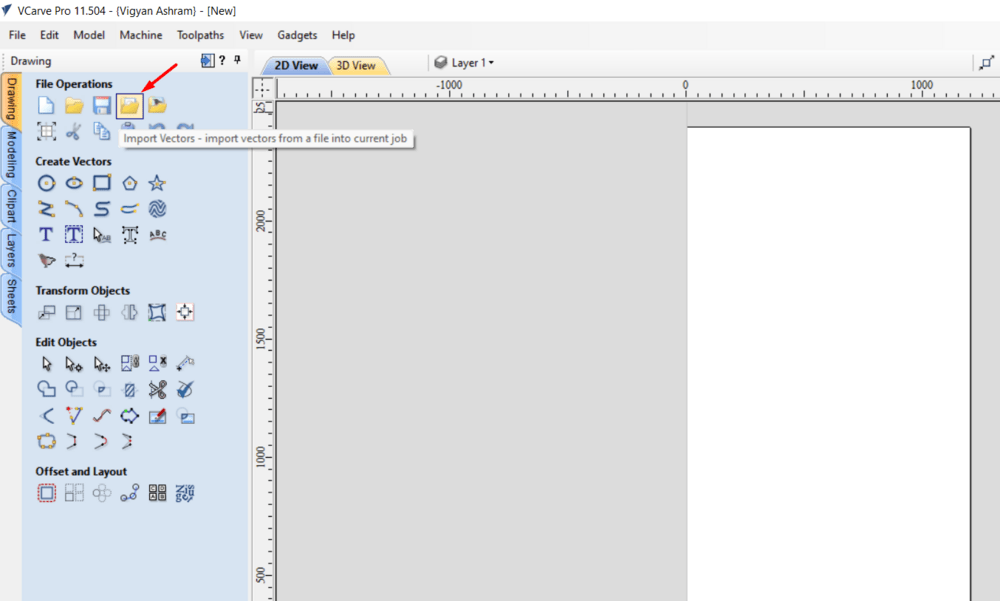
Then you have to load your dxf file here and check the drawing is there any double line or dots are present in design. if yes then we have to erase it.
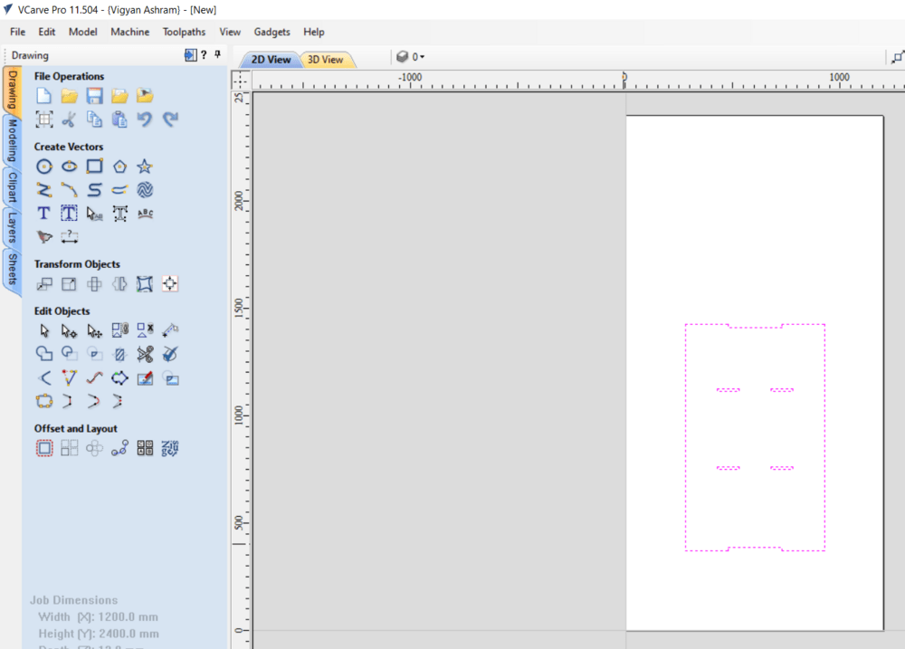
After uploading design as above we have to click on the join vector.
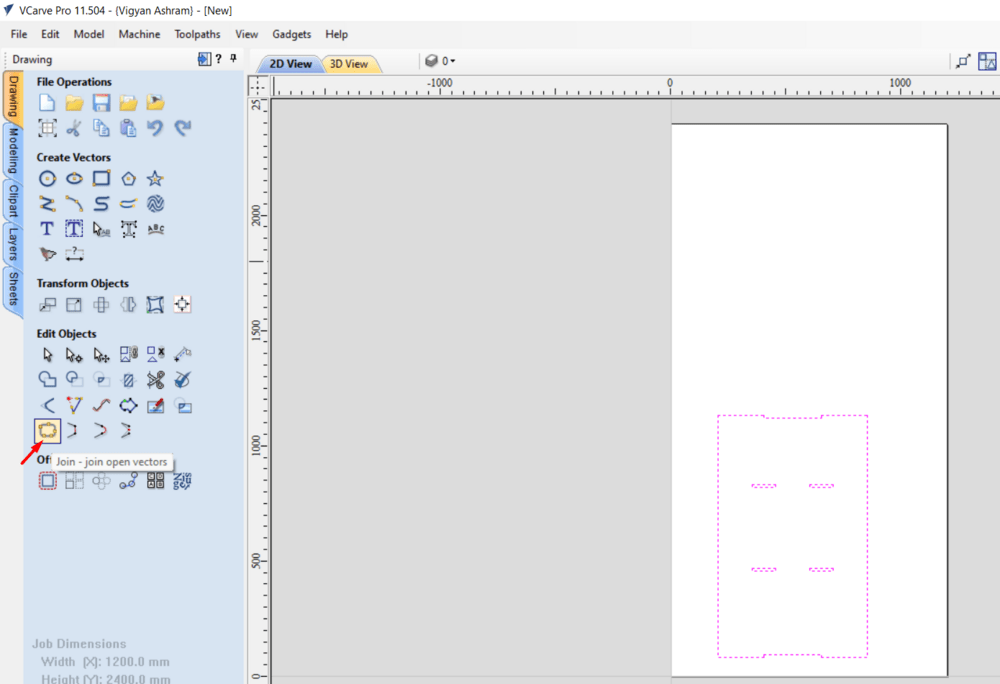
Again I add one design. After clicking to join vector button one window open as in picture. Here we can see XY position.
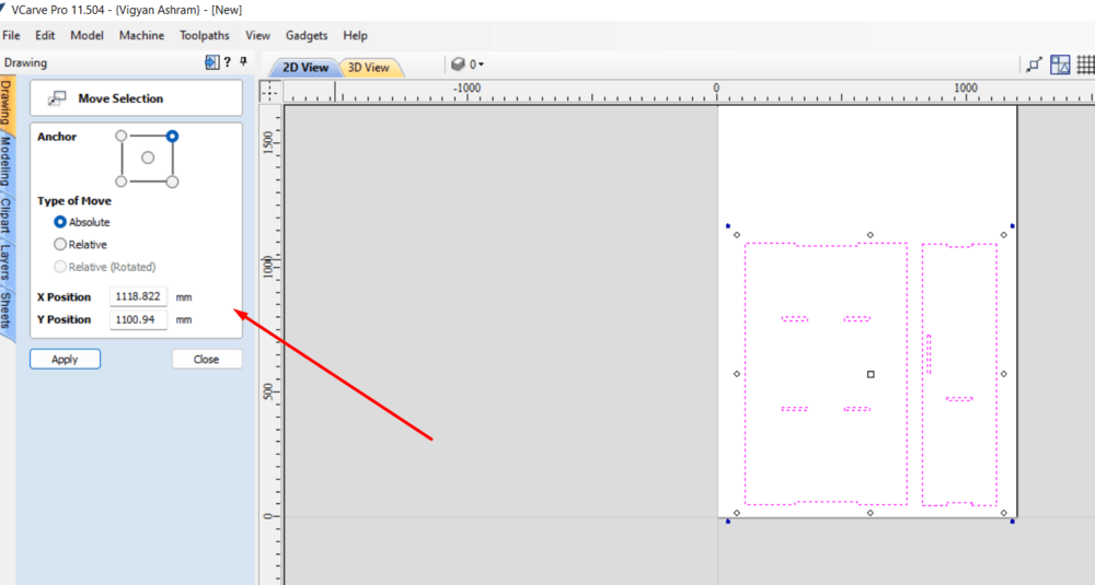
4. Manage your all design files in sheet
You can direct create vector here for different shapes like rectangle, pentagon and more. As I have design file in dxf format so imported that files and tried to manages it on sheet.

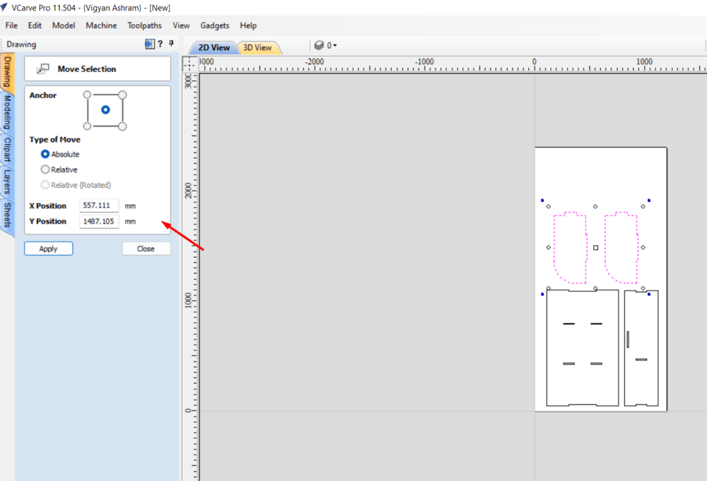
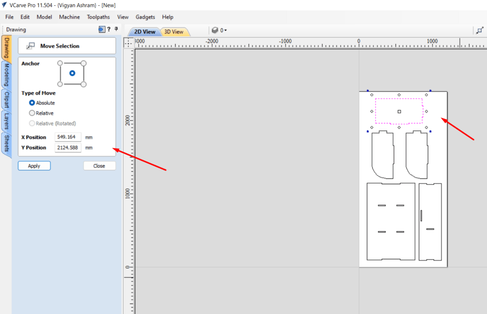
Similarly, as above join vector.
5. Set the ToolPath
1. Material Set up
Click on the toolpath at right corner and Set up material which we are going to cut.
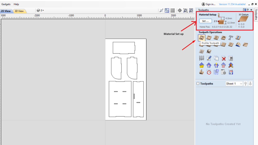
2. Cutting Depth
Then click on the Profile Toolpath shown above image and set the cutting parameter. Here I set cutting depth as start Depth = 0mm and and End Depth = 12, as I used 12mm thick plywood sheet.
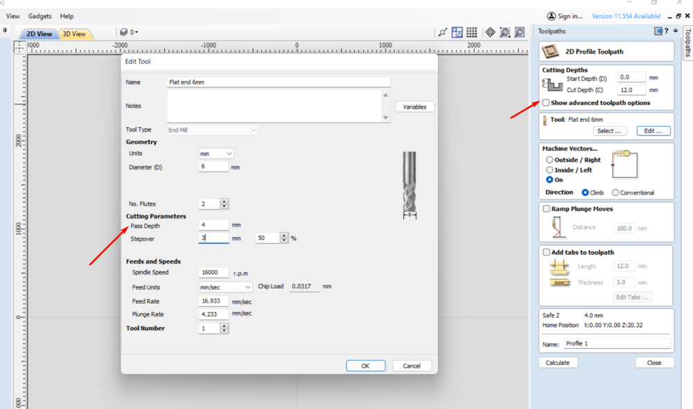
3. Select End Mill and Cutting parameter.
Then Set the tool as we have Flat end 6mm for cutting and cutting parameter.
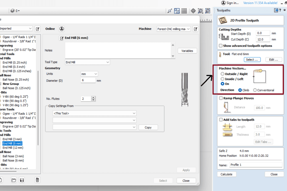
4. Select Machine Vector
After selecting the tool there is Machine vector which we have to select then name it and calculate.Machine vector are:
1. Outside (for external dimensions)
2. Inside (for inside dimensions,for ex,slot)
3. On
After selecting toolpath I got the design as below.As we see there is black line in some places instade all pink dotted line.
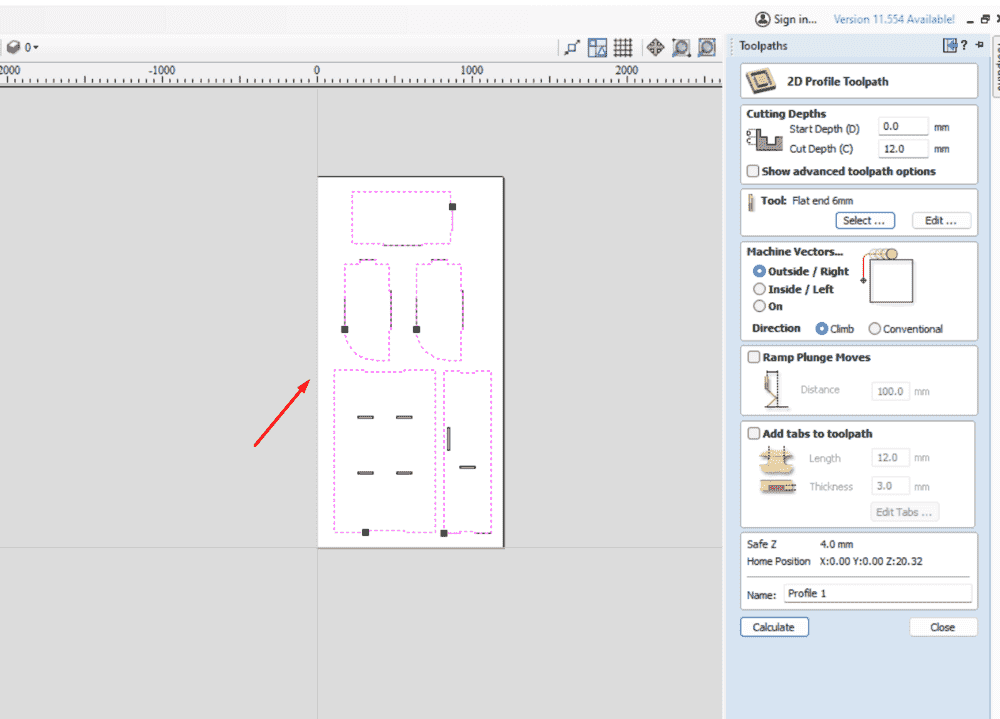
5. Calculate
Then Click on calculate
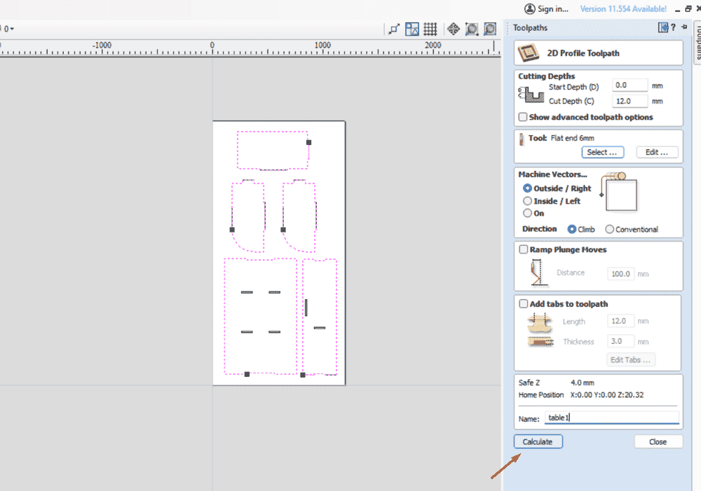
Here I get error massage for open contour as there is double line in design. Here take more time to resolve this. finally I understand the exact problem and edit that sketch in CorelDraw for removing that double line.
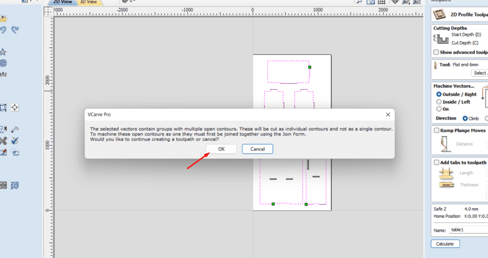
Then Click on OK Button to notification.
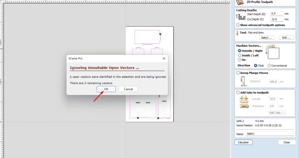
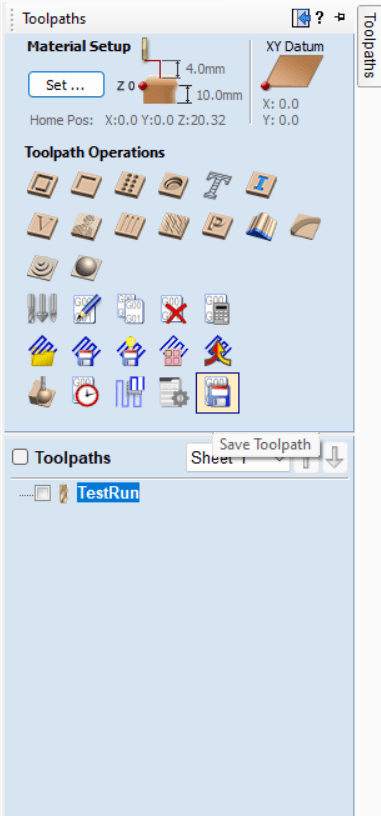
6. Save the Toolpath
Then I saved the toolpath as TAB 2 and checked preview.
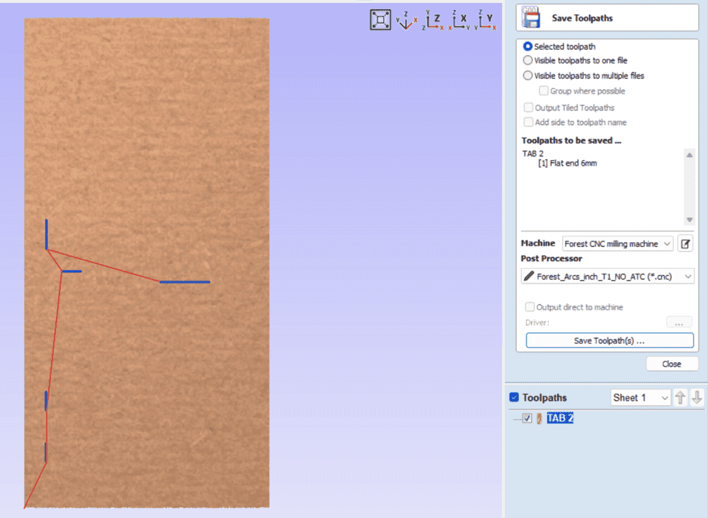
This is the problem where I was not getting all cutting only proper. After removing double line as above and setting XY position I get correct toolpath.Here I struggled more during resolving this issue.Thanks to Bhushan and Shanker who guide me to resolve issue.
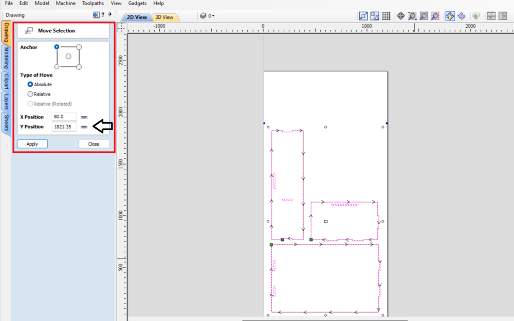
From XY position we have to check whether we have selected the proper job size or not. Also check drawing whether it contains double line. It create problem during creating toolpath. Finally get the toolpath and saved it into pendrive and the files are ready to cut on the wood router machine.
6. Cutting on Wood Router Machine
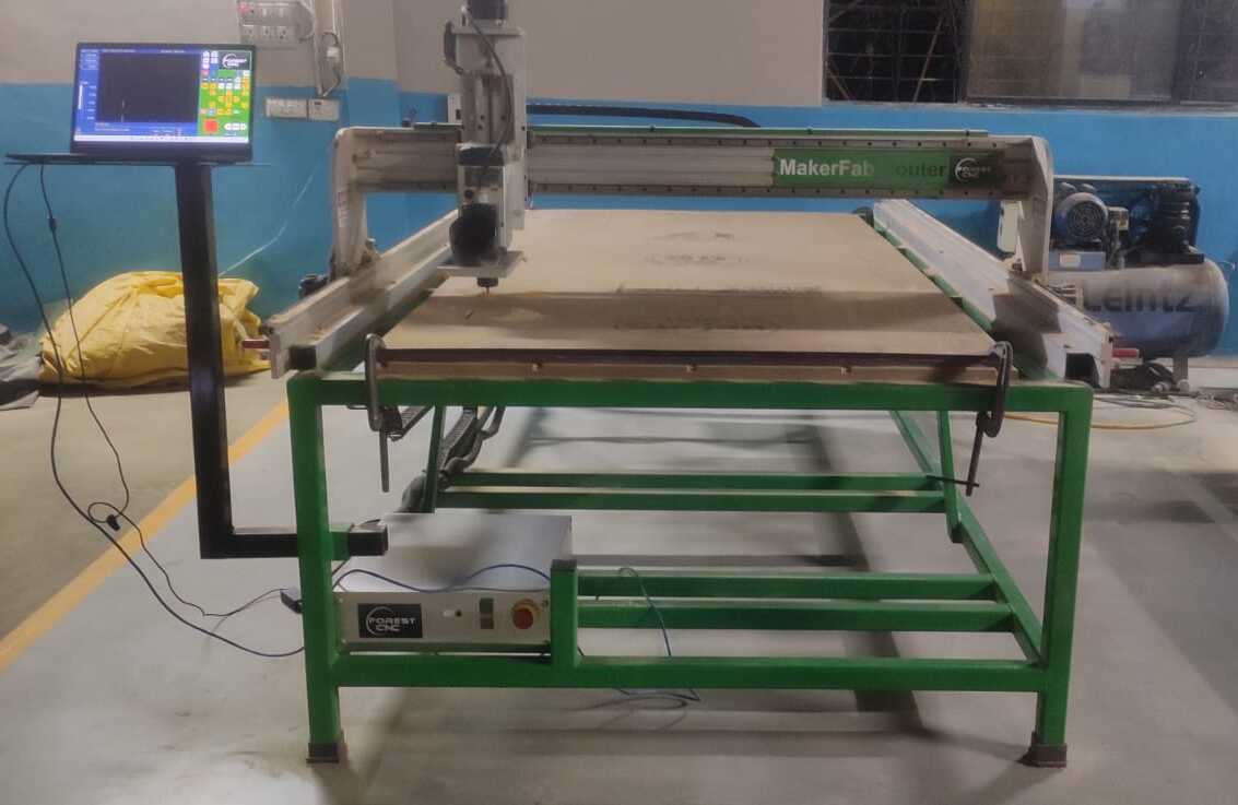
As above I have linked the details about the CNC wood router machine. In our vigyan Ashram we have Forest CNC Maker Fab Router.
1. Start the Wood Router machine
Turn on the machine's power.
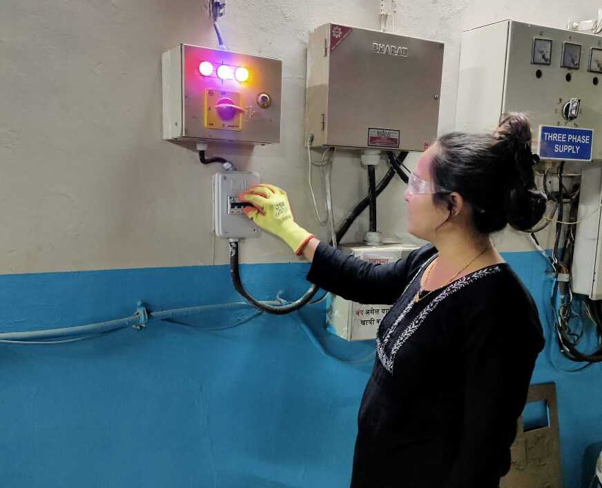
2. Fix the Cutting sheet
Fixed the 12mm plywood sheet on the machine bed with the help of clamps.
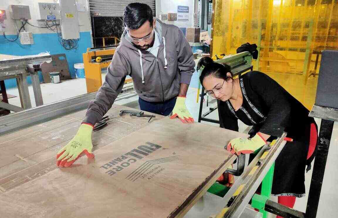
3. Fixed the end mill
Remove the old end mill if change.
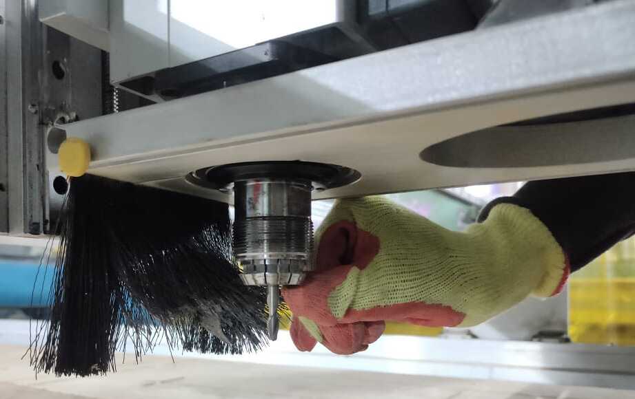
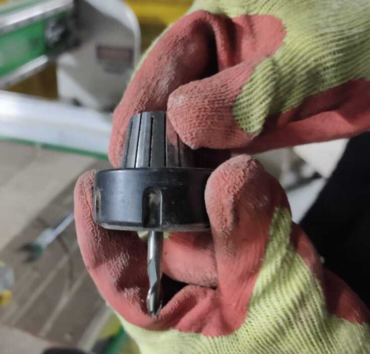
As I used a 6mm flat end mill for toolpath generation, I fixed the 6mm flat end mill to the collet.
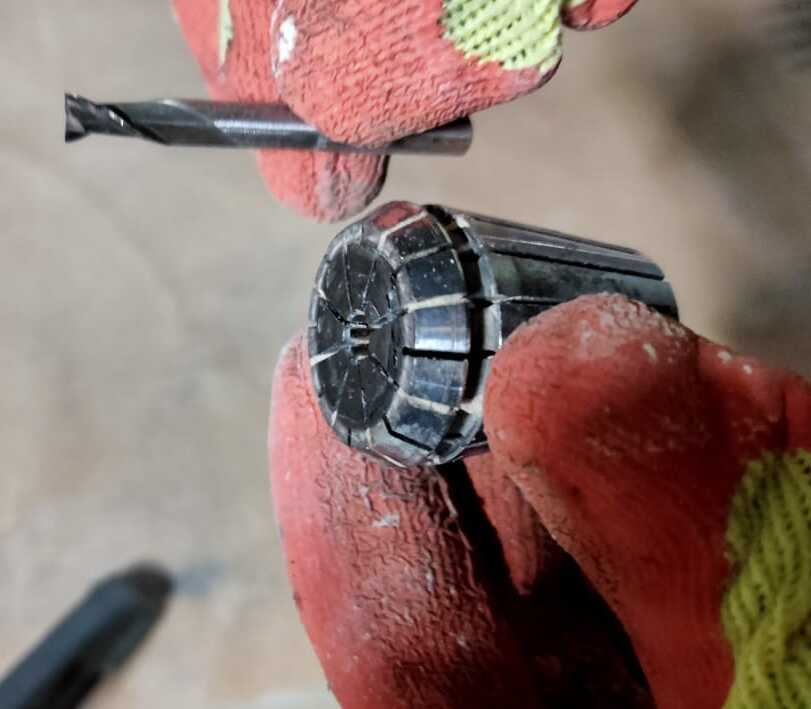
4. Start the machine Software
Start Machine software Router Control and move the head back to the machine's home position.

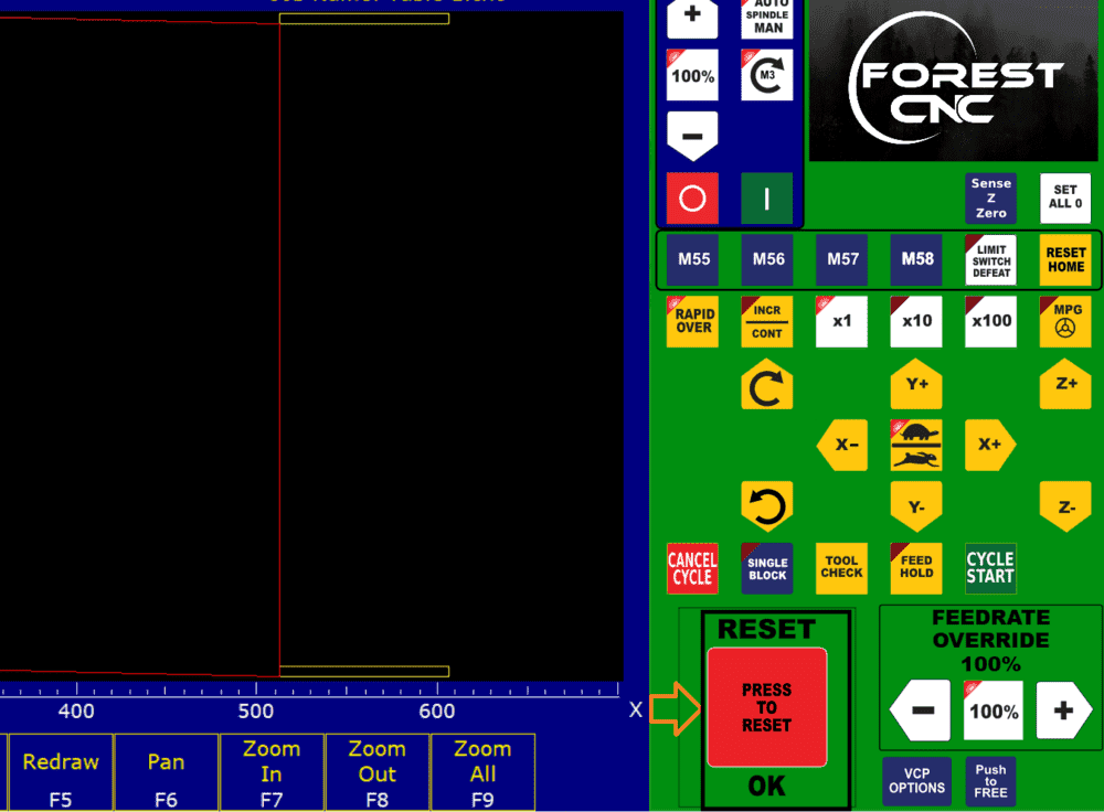
5. Press the Reset button
Press the Reset button as in picture.
6. Reset Home and Align zero
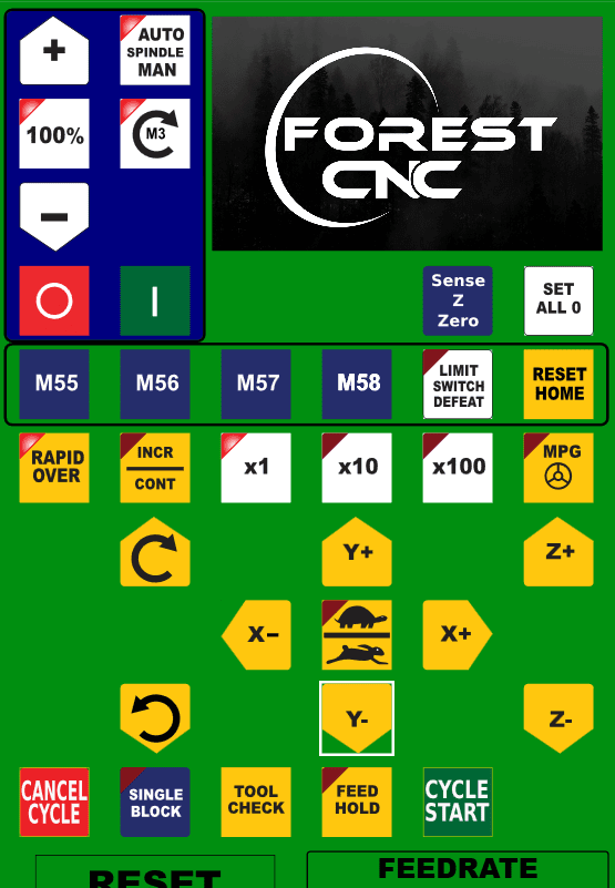
Now Select RESET HOME to set the home position of machines.
Position the head over the desired area of the cutting sheet and align it to zero on the sheet surface.
Finally, establish the origin by clicking on Set All Zero. Click each axis one by one and set them to zero.
7. Load the file
By clicking Load button as shown in photo select our file from pendrive.
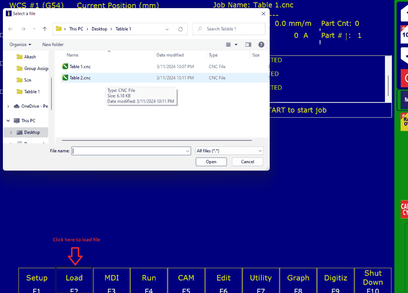
File is look like after loading
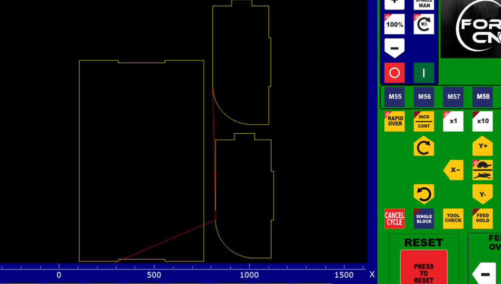
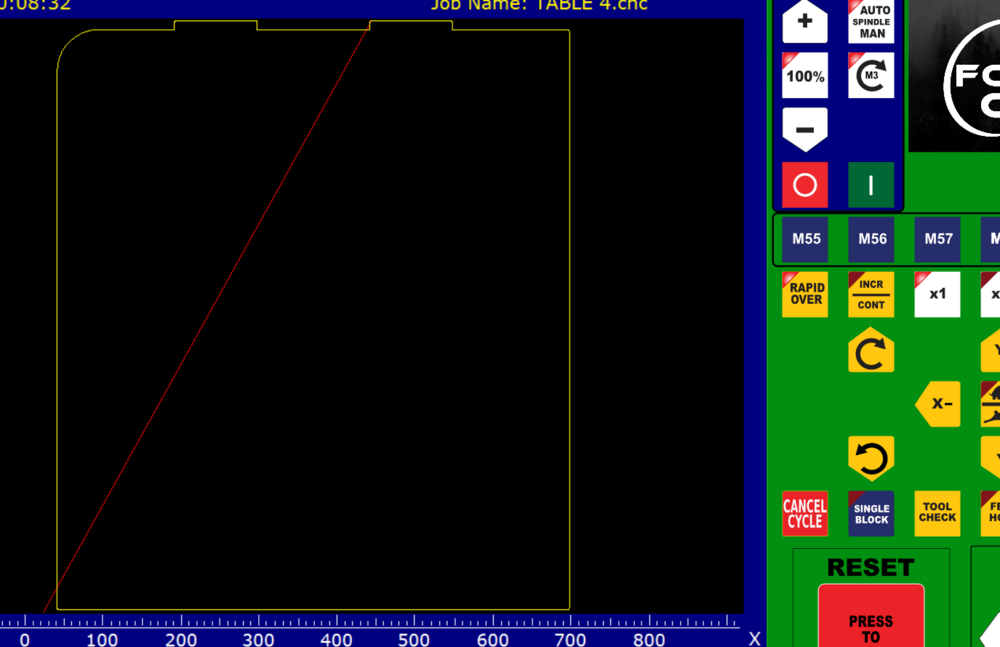
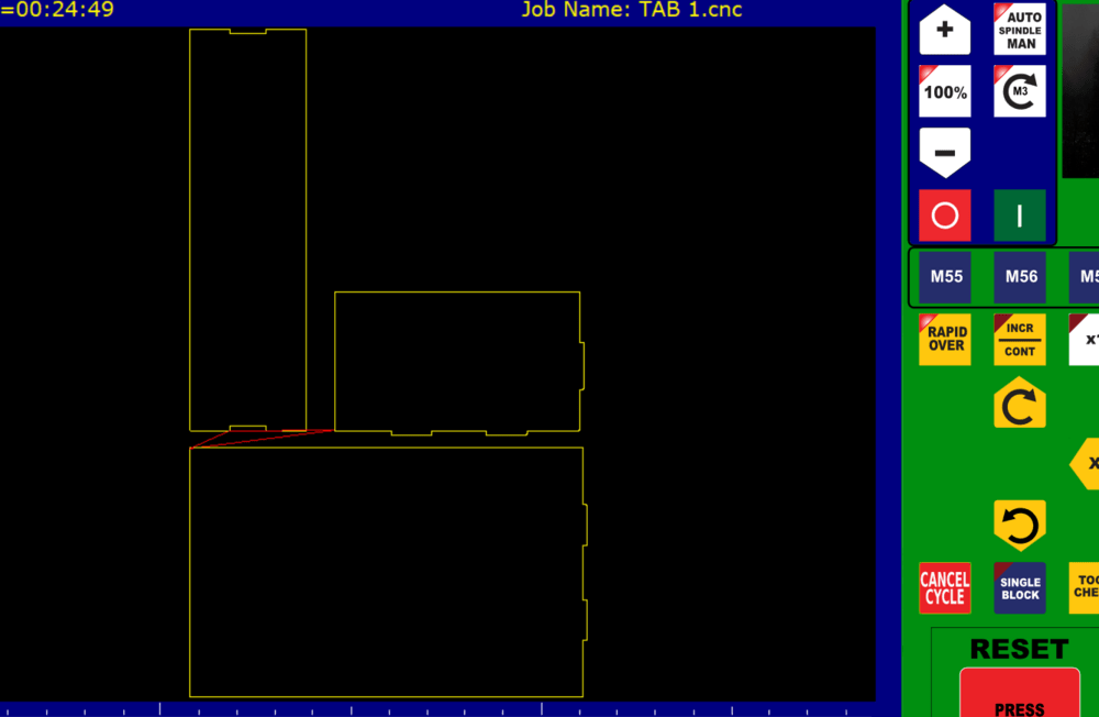
8. Start Cycle
Then click on start cycle button as shown in picture.Our cutting is in progress.. so we have cut part successfully.
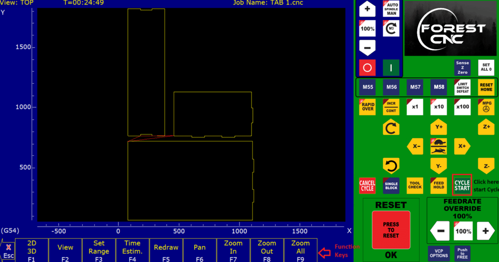
The Part are ready for assembly.
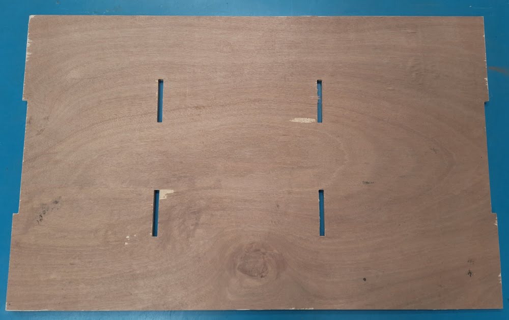
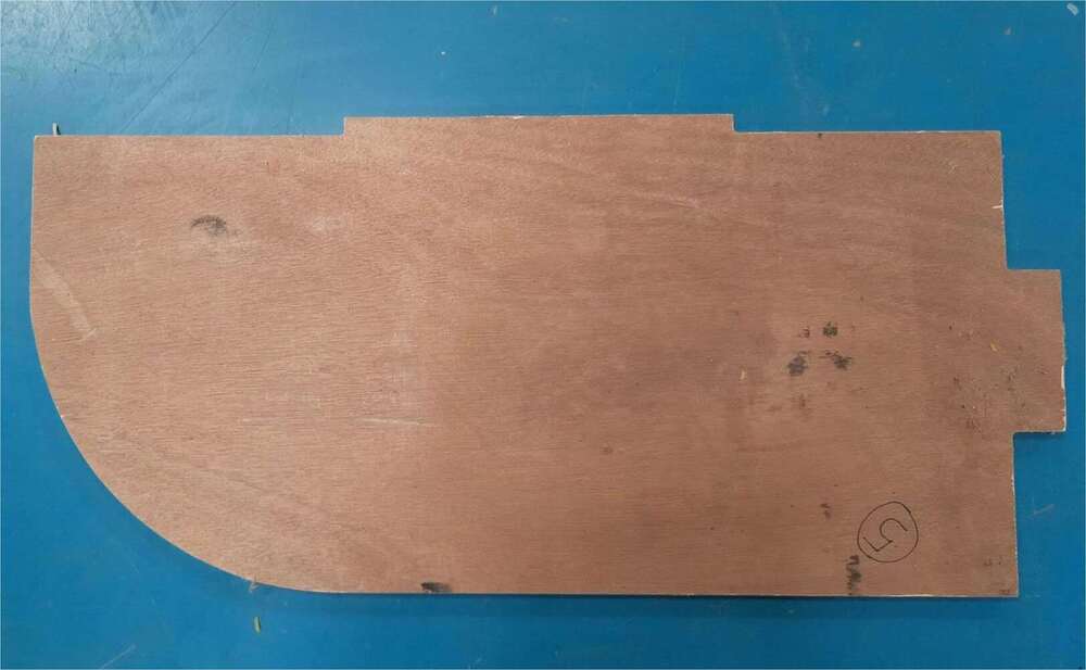
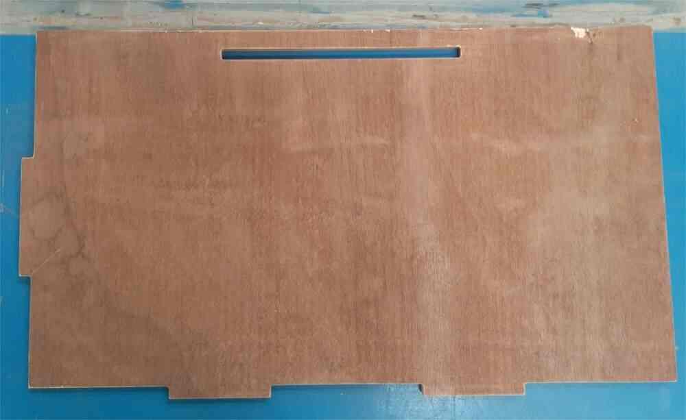
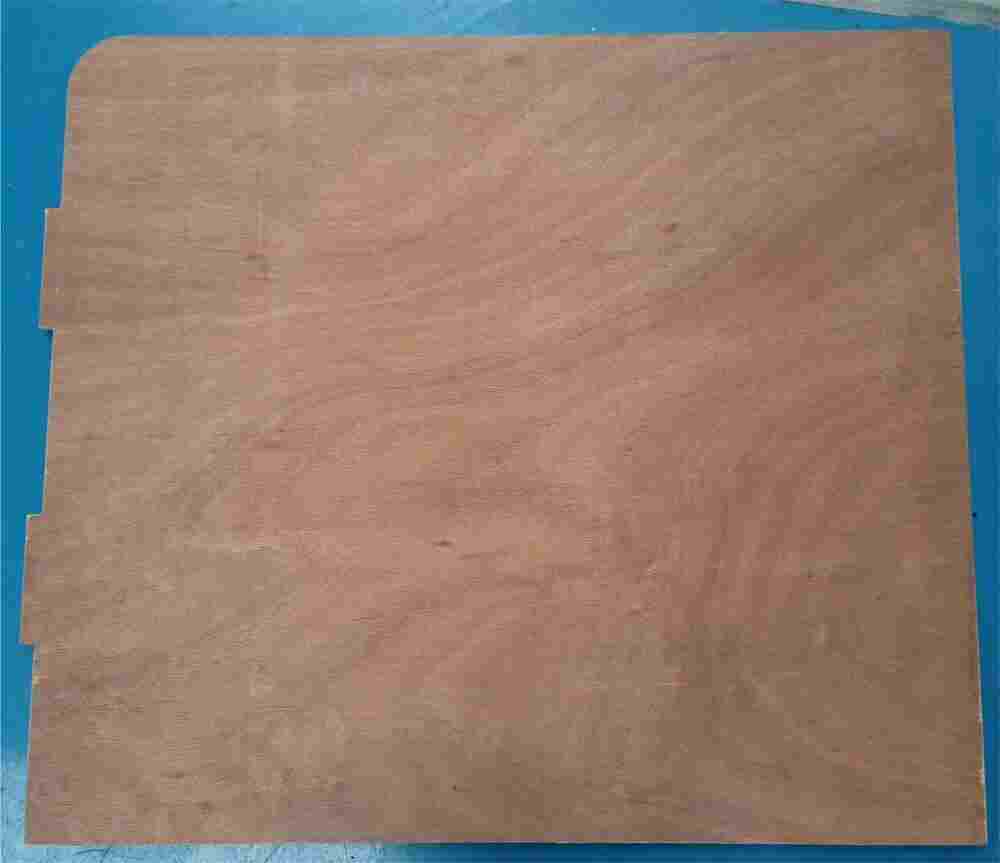
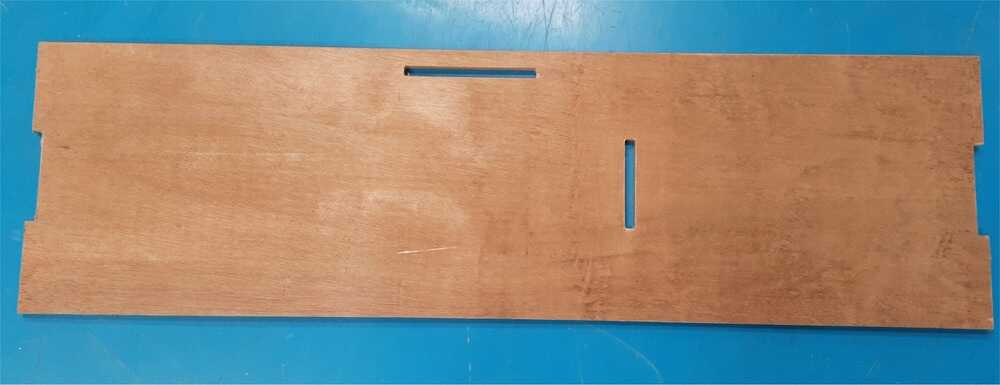
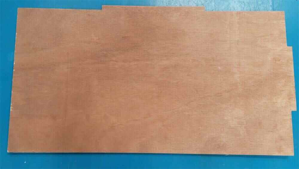
After assembly the table is ready.

Key Learning
During this assignment I learn about the process of operating the CNC wood router with design, toolpath generation, cutting,
assembly with safety.
I faced problem during tool path generation and learn about the double line in design should be romoved for tool path generation.