System Integration
Individual Assignment
Work Flow Chart
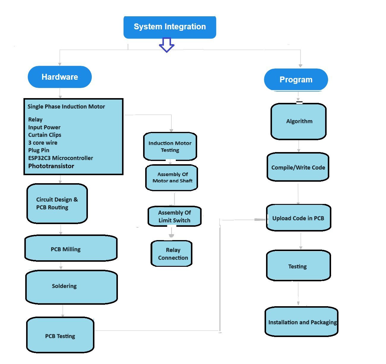
Design and document the system integration for final project.
During this assignment, I used some of the processes, components and motors listed below to complete my curtain automation project.
As part of our Fab Lab at Vigyan Ashram, we work on real-time problem-solving projects. I chose a project related to polyhouse automation. We received a customer/farmer's requirement for a curtain automation system. After identifying the problem statement, I have done brainstorming for the project. before that I share the structure of Our Polyhouse at Vigyan Ashram.
Our Structure for the Polyhouse
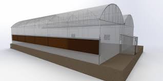
In our polyhouse, we are growing capsicum. The total area is 50 by 80 feet. The polyhouse has a dome-shaped structure, covered with white polyethylene. Below the dome, we have white curtains, which are also referred to as shade netting.The polyhouse structure look like....
As my project is Shadenet Automation, For the shade netting in the polyhouse, we have a single shaft that can rotate both clockwise and counterclockwise, winding the wire ropes around it. The shade net is attached to the wire ropes using clips that slide along the ropes, allowing for the opening and closing of the shade net. The main shaft is currently operated manually using an auxiliary handle.
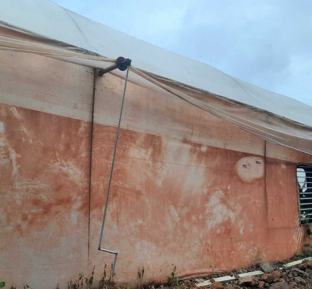
My project objective is to automate the rotation of the handle. The first step is to rotate the handle both clockwise and counterclockwise by attaching a motor to the shaft.The main shaft, and inside the polyhouse, the structure is like...
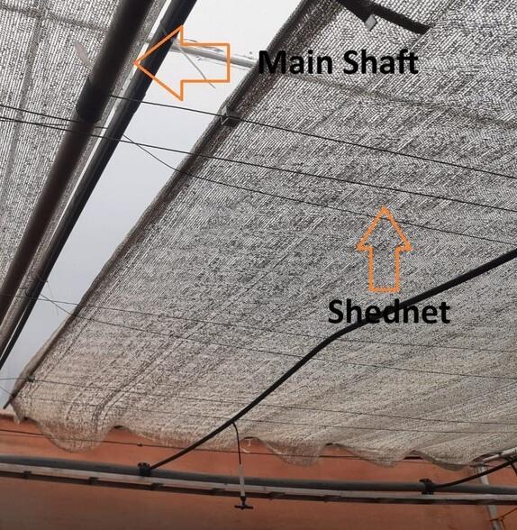
As shown in the picture above, there is a main shaft that rotates along with the auxiliary handle. I also measured the rotation of the auxiliary shaft in relation to the main shaft. Seven rotations of the auxiliary shaft result in one full rotation of the main shaft.
I want to attach a motor to enable manual rotation with the help of the motor. First, I need to select the appropriate motor, which requires knowing the torque value. To calculate the torque, I need to determine the total load.
Torque Calculations
First I find the total load.
Total Load = Weight of Main Shaft + Weight of rope wire + Weight of shadenet
Motor Selection
As we have workshop inventory, I found a motor from there. I have selected a single-phase induction motor with the following specifications.
Single Phase Induction Motor
Power: 0.5 hp
RPM: 1440
Voltage: 230 ± 10 %
Current: 2.2 V
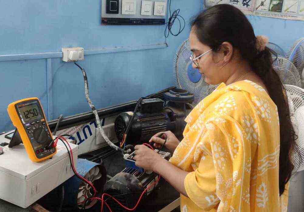
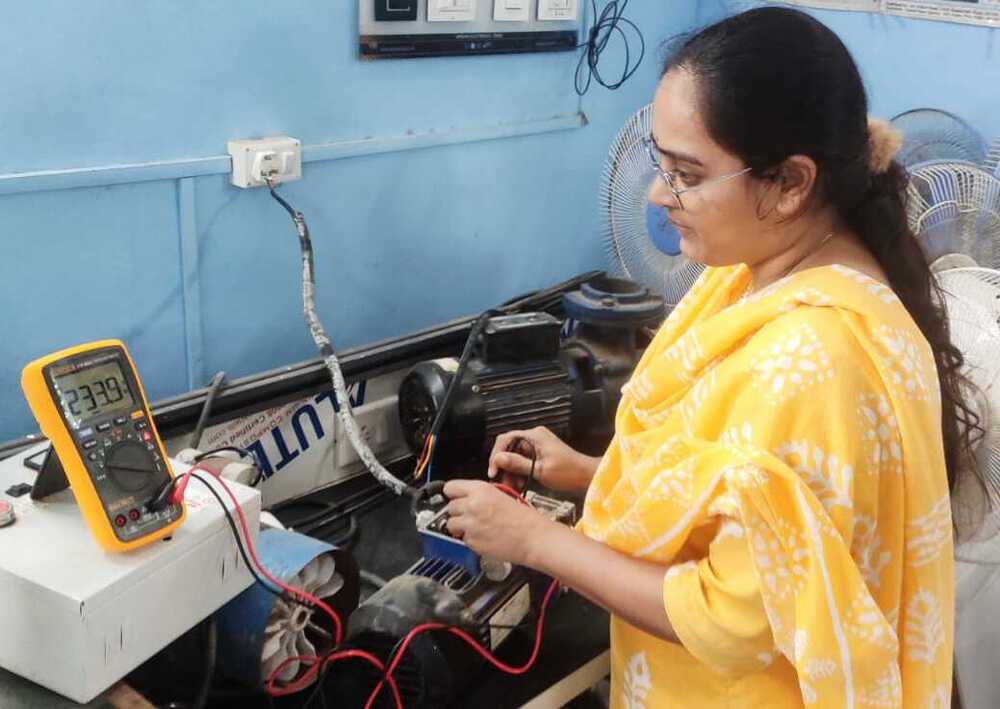
After selecting the motor and calculating the required torque, I tested the motor to check if it was working properly and measured the actual voltage and current using a multimeter.
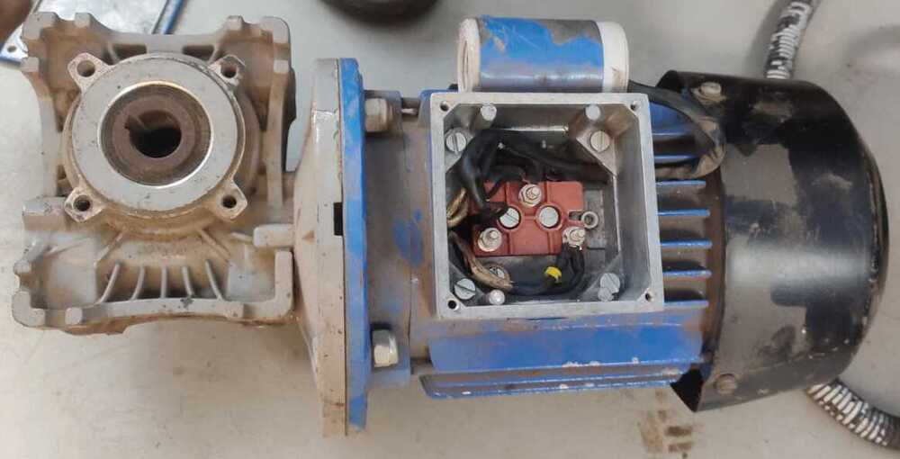
Internal connections of the machine
Actual current measured
Actual Voltage measured
Pin connections
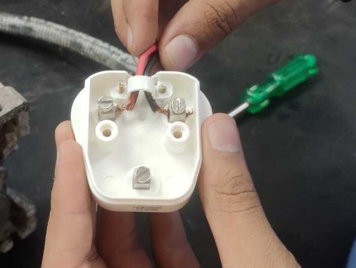
After checking the wire connections, I plugged in the pin to the AC supply to test whether the motor was working or
not.
The motor is in working condition. Since this motor has 1440 RPM, we require lower RPM and higher torque, so a gearbox is attached.
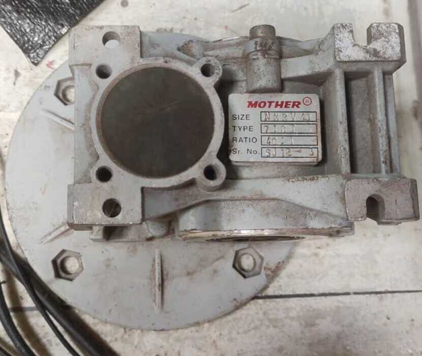
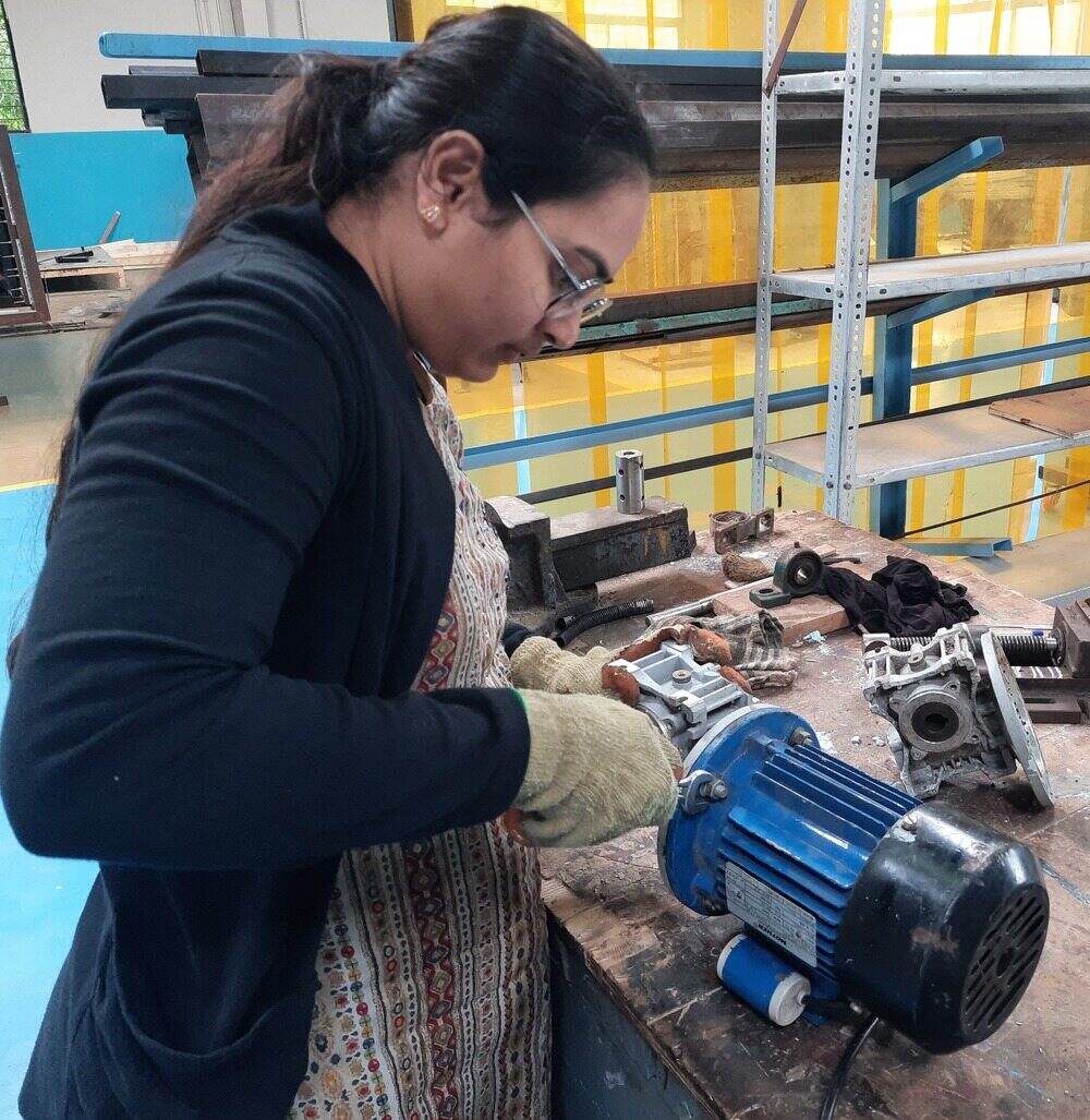
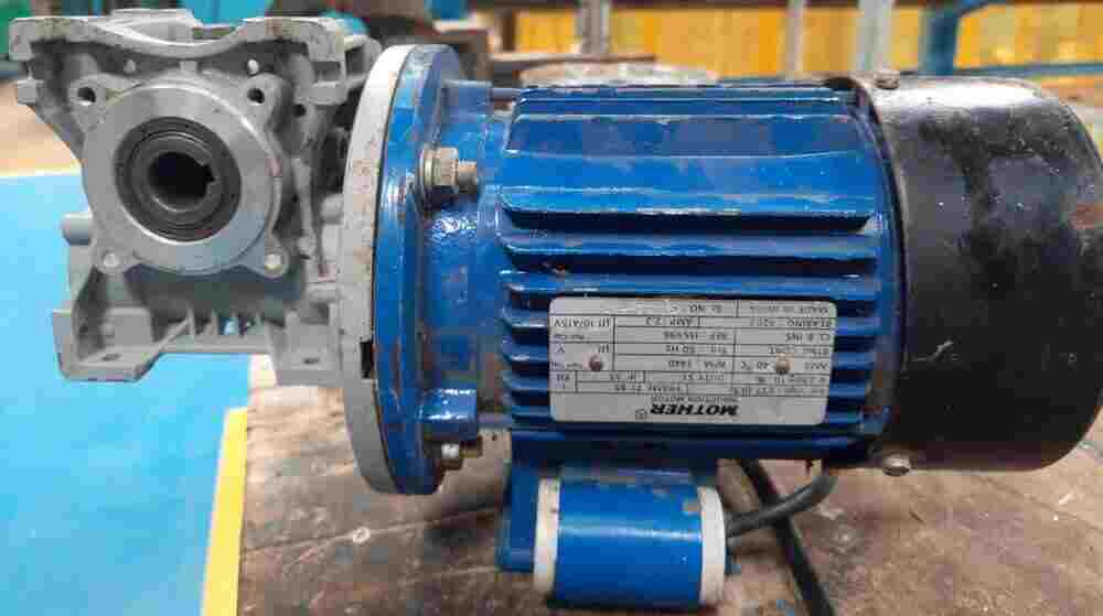
As the gearbox has a 40:1 ratio and the motor runs at 1440 RPM, the RPM after attaching the gearbox can be calculated.
RPM After Attaching Gearbox = (1440 X 1)/40
= 36 r.p.m.
I also rechecked the calculation practically by measuring the rotation visually over the span of one minute.
Fabrication
I have the task of making a stand to hold the motor, ensuring that the height is properly set to align with the shaft in the polyhouse. Initially, the main shaft is rotated manually, so the shaft needs to be fixed to the motor's output, which is connected to a gearbox attached to the motor.
First, we removed the shaft used for manual operation. The shaft was fixed to the main shaft with a nut and bolt, so we simply removed the nut and bolt to take out the shaft for cutting, with the help of my colleagues, Yogesh, Bhushan and Sumit.
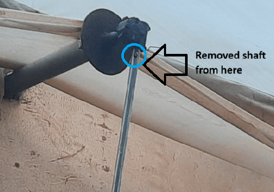
Then cut the front portion.
Then I moved towards the fabrication. Bhushan guided me on the choice of material, welding, and fabrication techniques.
Design for Motor Stand
First we make design for motor holder in solidworks.
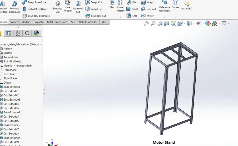
Then selected the material and collected it from the workshop inventory.
Material used for Fabrication...
I needed a stand to hold the machine, so I fabricated one using Stand material.
(1) MS Angle 25×25×5
(2) MS flat patti 30×5
(3) MS Square Tube 25×25×2
First, I took the MS angle and cut it into four pieces of the same dimensions as 25 X 25 X 5
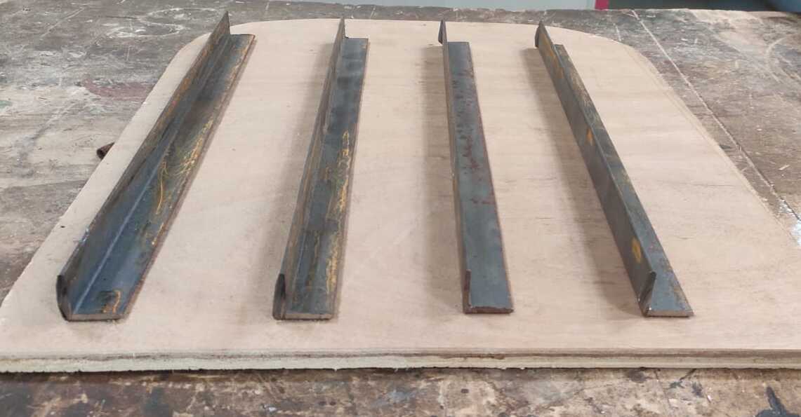
Then given cut at 5mm from end at both side for welding purpose.
Then, CO2 welding was performed to join the four MS angle pieces.
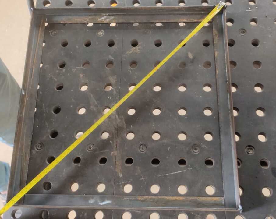
After welding is completed, perform grinding to smooth the surface.
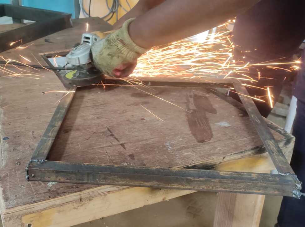
I take two flat plates and drill them, then weld them to secure the motor. Additionally, I weld three flat plates inside the square frame to provide support for the assembly above.
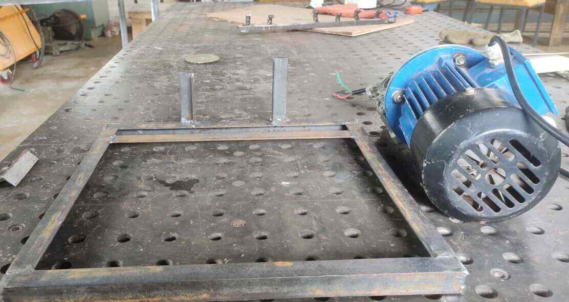
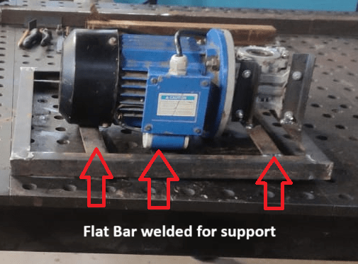
Then, cut four MS angle pieces to the same length as the legs of the motor holder.
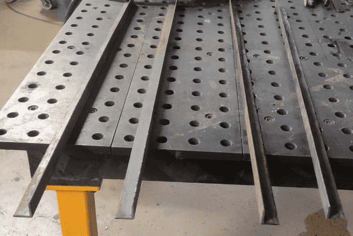
After welding all the joints, the motor stand was ready. The motor was then mounted on it using nuts and bolts.
I got a shaft from our workshop inventory to fix it in the gearbox attached to the motor outlet, along with a key to secure it. My task was to reduce the diameter at the front, so with the help of a lathe machine, the turning operation was done, and I used a milling machine to make the key slot.
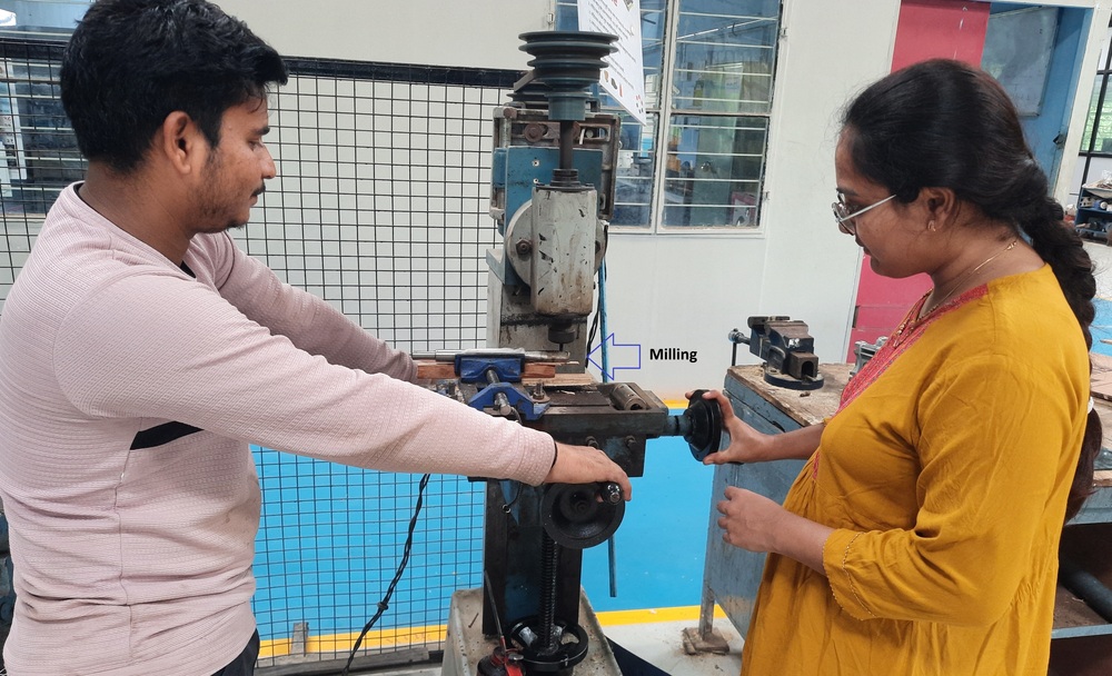
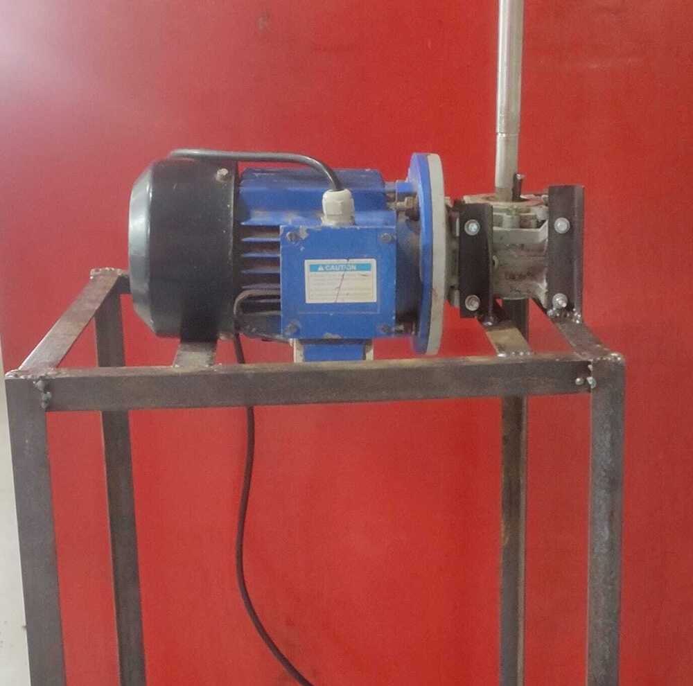
With the help of my colleague, I fixed the motor outside the polyhouse where I needed to attach the shaft to the motor outlet. We dug a large pit, leveled the ground, and placed the motor with its stand in it.
Components and machines
LDR Module
In my project, I have used an LDR sensor for curtain automation in a polyhouse.
Specificaion
Operating Voltage: 3.3V to 5V DC
Operating Current: 15ma
Output Digital - 0V to 5V, Adjustable trigger level from preset
Output Analog - 0V to 5V based on light falling on the LDR
LEDs indicating output and power
PCB Size: 3.2cm x 1.4cm
LM393 based design
Features
Can detect ambient brightness and light intensity
Adjustable sensitivity (via blue digital potentiometer adjustment)
Output Type: Analog and Digital
With fixed bolt hole for easy installation
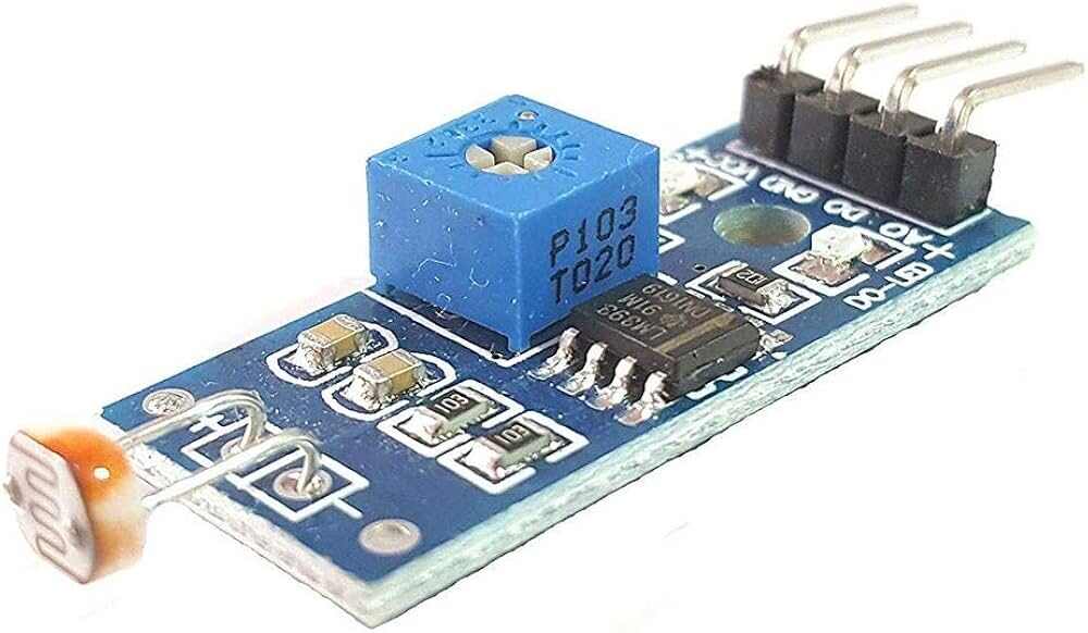
Initially, I used an LDR module, but after my global instructor recommended switching to a phototransistor, I made that modification.
Phototransistor
A phototransistor is a light-sensitive component that acts as both a switch and a current amplifier, responding to light rather than electrical input. When exposed to light, it generates a reverse current that corresponds to the intensity of the light. Phototransistors are widely utilized to detect light pulses and convert them into digital signals. Their high gain, affordability, and flexibility make them useful for a variety of applications. I reviewed information on the phototransistor from an online source. Refer Link
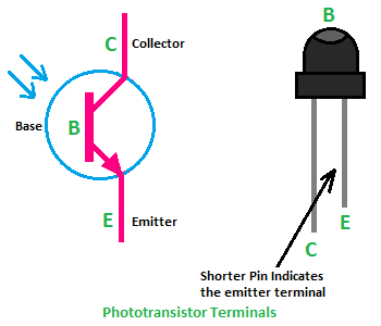
Induction Motor
An induction motor, also called an asynchronous motor, is a widely used type of AC (alternating current) electric motor. It works by creating a magnetic field in the stator (the stationary part of the motor) that induces an electric current in the rotor (the rotating part). This current in the rotor produces the force, or torque, needed to turn the motor. The rotor can be of two types: a squirrel cage rotor or a wound rotor. Read More
After calculating the torque, I selected this single phase induction motor from our inventory to rotate the shaft for opening and closing the curtains.
PCB Design
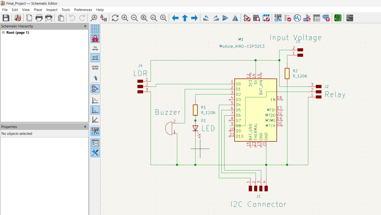
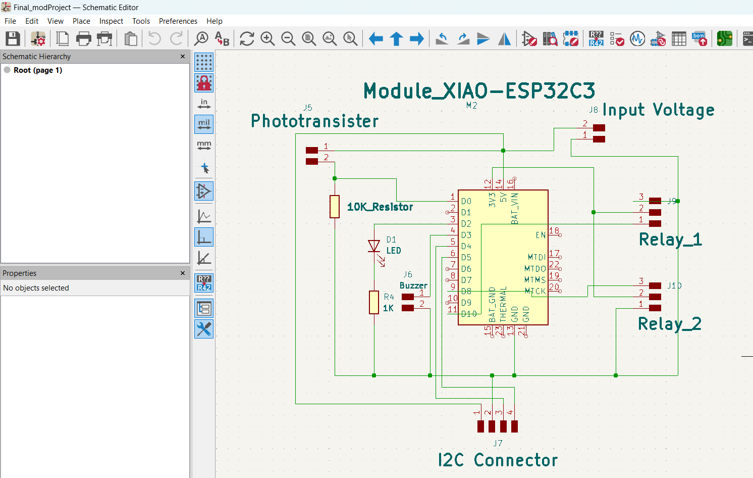
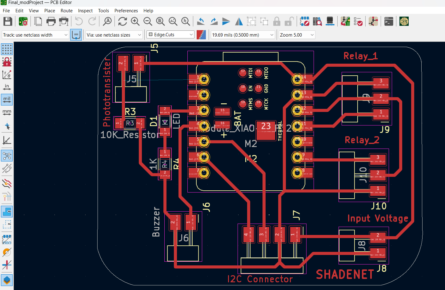
I then designed a PCB for my project. On it, I made four connections: one for the LDR, two for the relay, one for the input voltage, and one for the I2C connector.
Schematic Diagram
PCB Editor
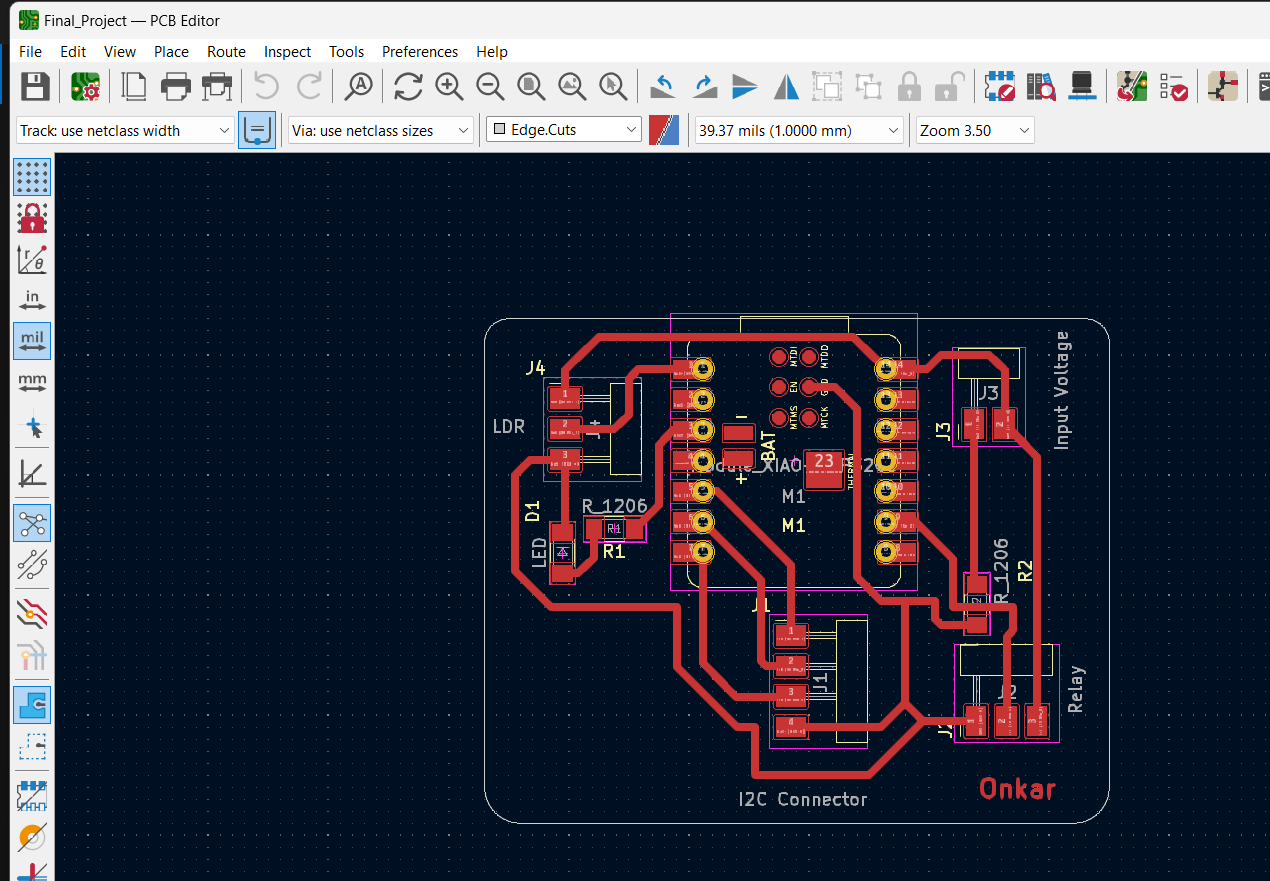
In the above design, the buzzer is not included as it is not required, so I kept this as the final version and milled the PCB.
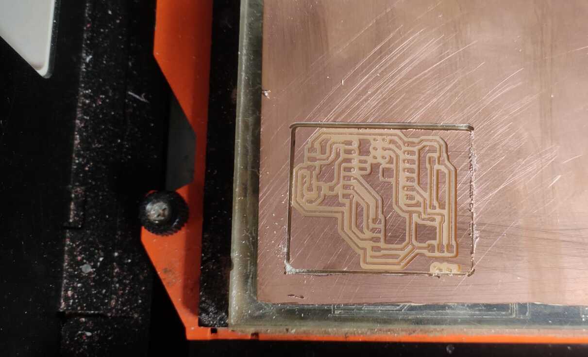
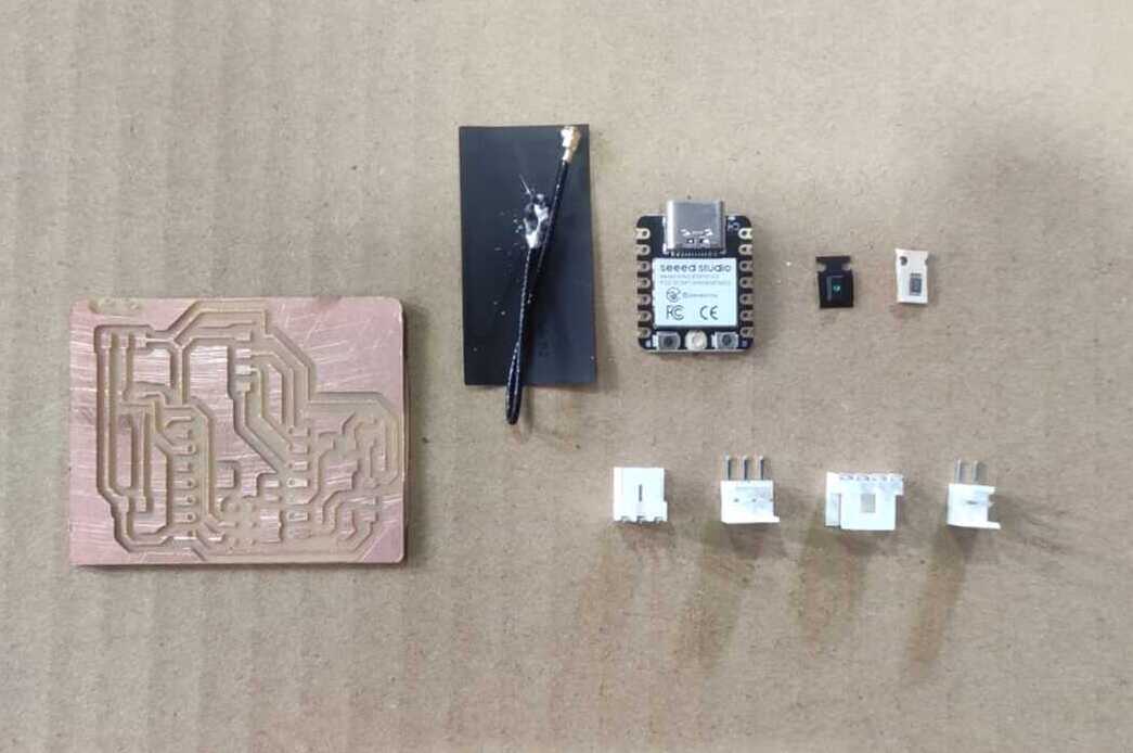
Then I done the soldering.
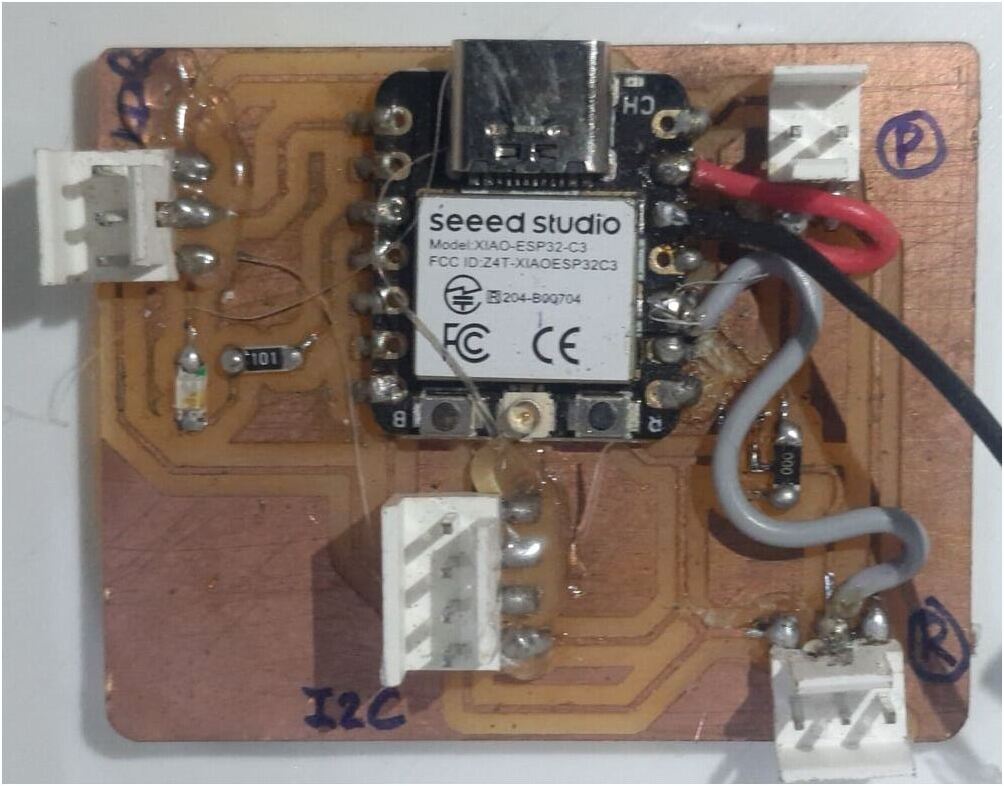
After soldering, I completed the final project PCB. However, I encountered an issue with grounding, as the ground was placed underneath the ESP32C3 microcontroller, causing problems with the output. My instructor, Mr. Suhas, helped me identify the problem, and I was able to fix it by using a jumper wire. The PCB is now functioning correctly.
Following the suggestion of my Global instructor Mr. Adrian, to replace the LDR module with a phototransistor, I redesigned the circuit using the phototransistor and also fixed the ground connection in the new PCB layout.
In the schematic and PCB editor, the PCB looks like.
Then I done routing ....
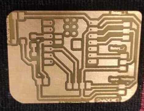
I used the Mods CE software to convert an SVG image into an .rml file and then milled the PCB using the Monofab SRM-20 milling machine.
After gathering the SMD connectors, microcontroller board, LED, and resistors, I completed the soldering process.
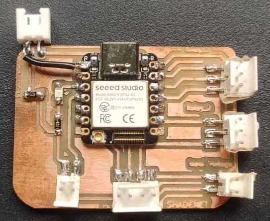
During the routing process, I made an error in connecting the phototransistor to the signal pin, so I corrected the connection by adjusting the soldered trace.
After completing the PCB, I needed to assembled the components, such as the Phototransistor and two relays, and design the controller box and then done programming.
Cad Design Of Controller Box
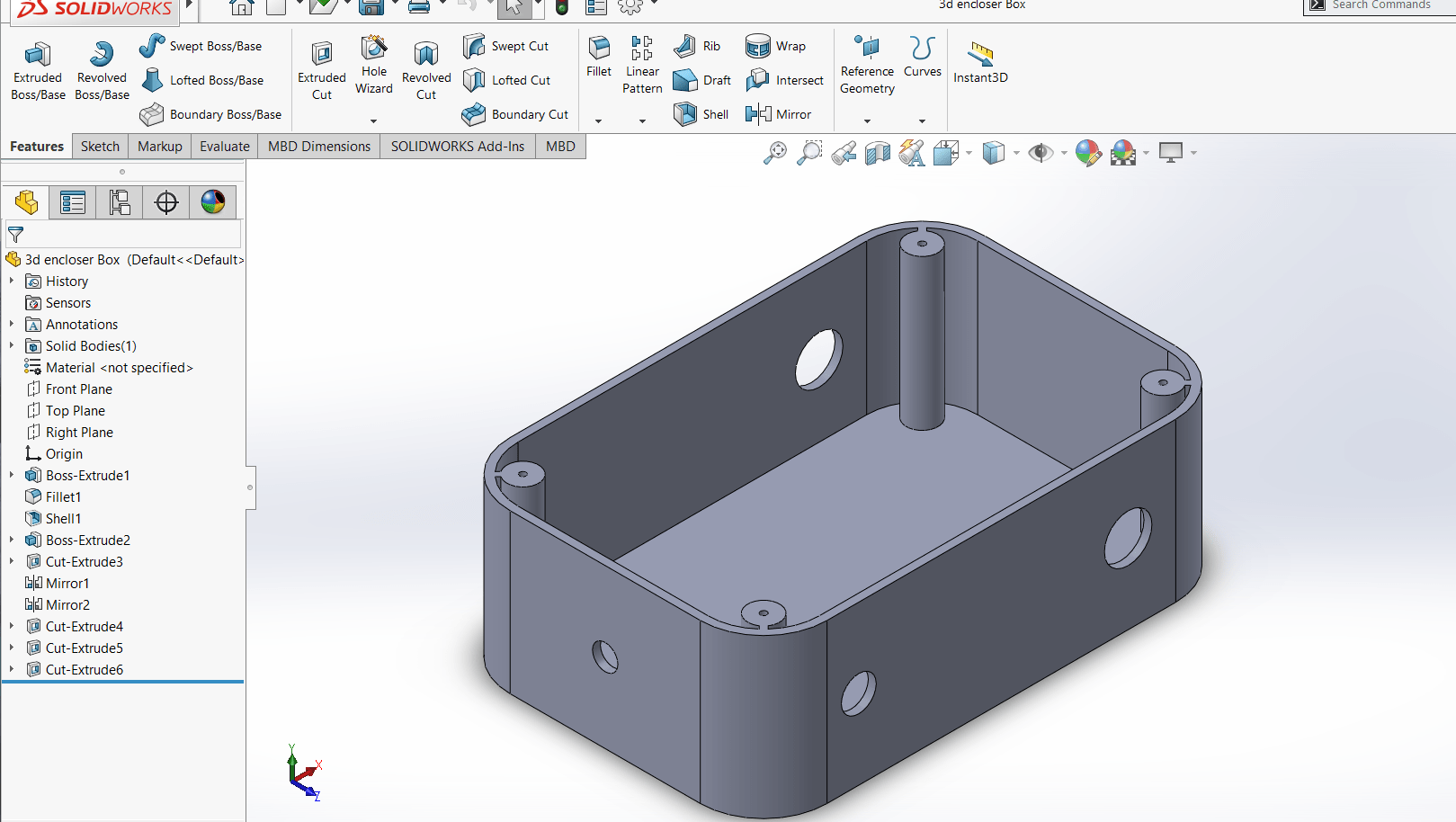
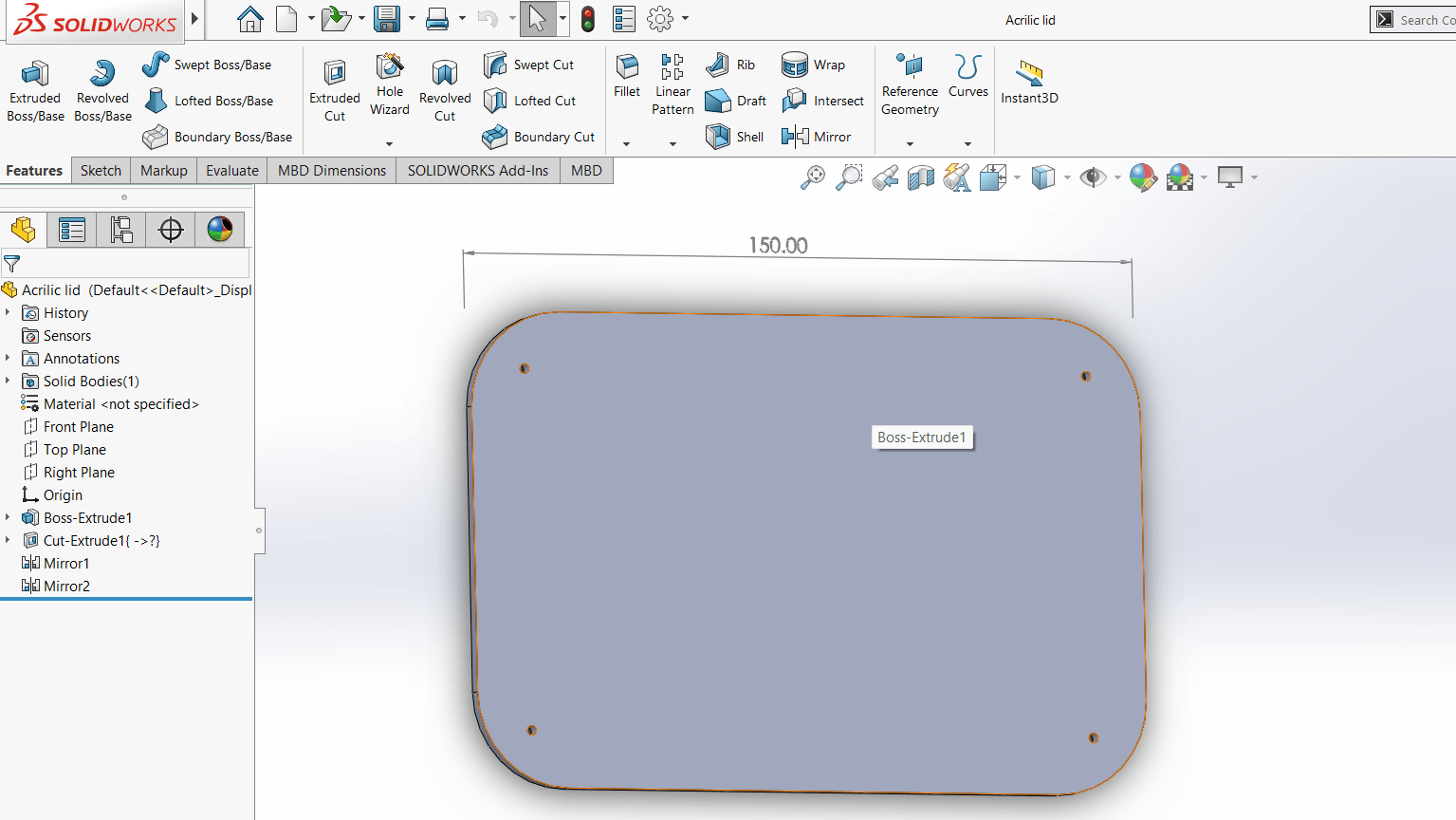
Next, I moved on to the production phase and chose to 3D print the bottom part of the controller box using our Flashforge 3D printer.
Using FlashPrint software, I convert the STL file into a G-Code format nnd used PLA material for 3D Printing.
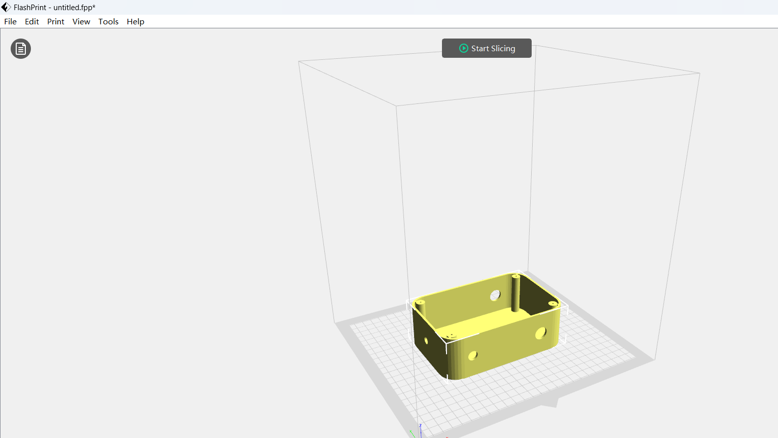
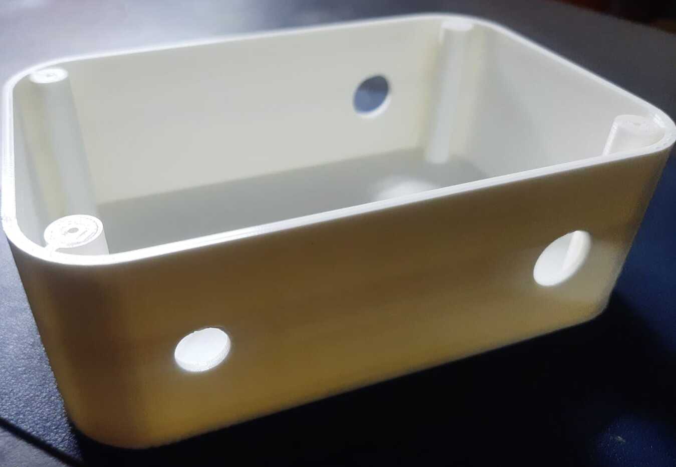
And finally 3D printed Controller Box is ready.
It is crucial to cover the box, so I designed a lid as shown above. I wanted something decorative or a transparent lid/cover, so I chose to laser cut the design using acrylic. I also plan to engrave my project name onto the lid/cover using laser scanning.

On-site packaging and assembly in the polyhouse
Next, I set up the entire system I had developed in the capsicum polyhouse at Vigyan Ashram.