Output Devices
This week assignment I have to learn about output devives.In previous assignment I design a pcb and solder it.In this assignment I am going to connect output devicec to my microcontroller board.Learn about the different output devices and its connections. This week includes
Grop Assignment
Measure the power consumption of an output device. Find my group assignment link here..Read More
Individual Assignment
Add an output device to a microcontroller board designed in last week, and program it to do something.
What is Output Devices
An output device is a hardware component that takes data and instructions from a microcontroller or computer and performs specific tasks based on them. It converts electronically processed information into a format that humans can understand. These devices react to signals or data from other devices to produce outputs that can be interpret by humans through sight, touch, sound, smell, Temperature,taste and more.In daily live we used different devices like Printers, TVs, fans, computer screens, mobile phone screens,LED Nameplates to bus and motors. In case of microcontrollers, output devices include stepper motors, servo motors, DC motors, LCD displays, OLED displays, LEDs, relays, buzzers, and speakers.I will learn it and document it step by step.
Motors
Electric motors are machines that turn electrical energy into movement. They work by using magnets and wires to create motion. There are different types of electric motors, each with its own way of arranging the magnets and wires, and ways to control how fast or strong they move. Some common types include:
Series DC Motor
Shunt/Parallel DC Motor
Compound DC Motors
Permanent Magnet DC Motor
Servo Motor
A servo motor is a type of motor that operates using a DC power source. This power can come from either an external supply or a controller.
Read More
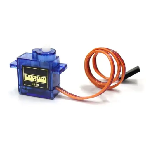
Micro Servo Motor SG90:
The SG90 micro servo motor is a small and lightweight type of servo motor that packs a punch with its high output power.
Applications:
SG90 servo motors find applications in various fields such as:
Cameras: For precise movement and focus adjustments.
Telescopes: For tracking celestial objects accurately.
Antennas: For positioning and alignment.
Industrial Automation: In machinery and equipment for precise control.
Robots: For controlling movement and manipulation tasks.
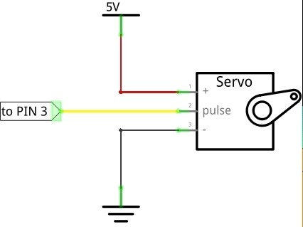
Circuit Diagram for SG90 Micro Servo
Specification:
| Specification | Value |
|---|---|
| Product | SG90 Servo |
| Torque | 2.0kg/cm (4.8V), 2.2kg/cm (6V) |
| Speed | 0.09s/60° (4.8V), 0.08s/60° (6V) |
| Rotate angle | 180° |
| Operating voltage | 4.8 ~ 6V |
| Gear | plastic |
| Dead band | 7us |
| Weight | 10.5g |
| Dimension | 22.8mm × 12.2mm × 28.5mm |
Programming
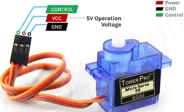
I have used above servo motor as an output device for this week assignment. I used ESP32C3 microcontroller board and I have three pin connection into my board. As servo motor has three wires Power,Ground and Signal. I have made this arrangement in my microcontroller board.I have given the Ground connection which is brown wire in my case for negative pole of my board , then I given the signal connection which is pin D10 and and last is the power connection by connecting the wires to servo motor and my connector on board in proper position.There should care must be taken while connections because if we have wrong connection of power pins there is chances of IC damage or may be our output device. I refer this image from google.
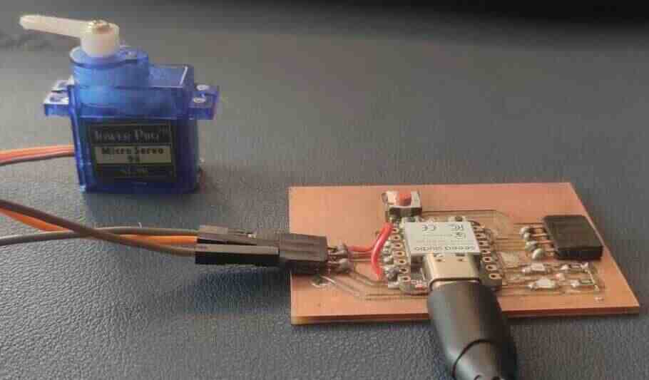
My servo connections
I used Ardino ide platform for coding. As the Ardino opens I have connected my board with the power cable with my program system. first selected the board because in my software previous board RP2040 is selected and also selected the port then I search for the program.
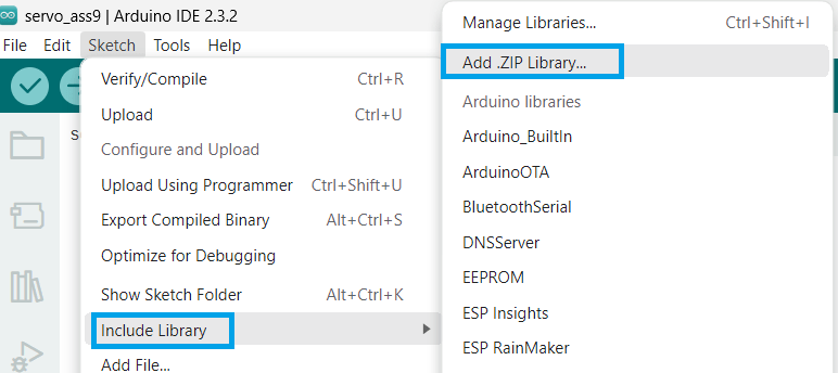
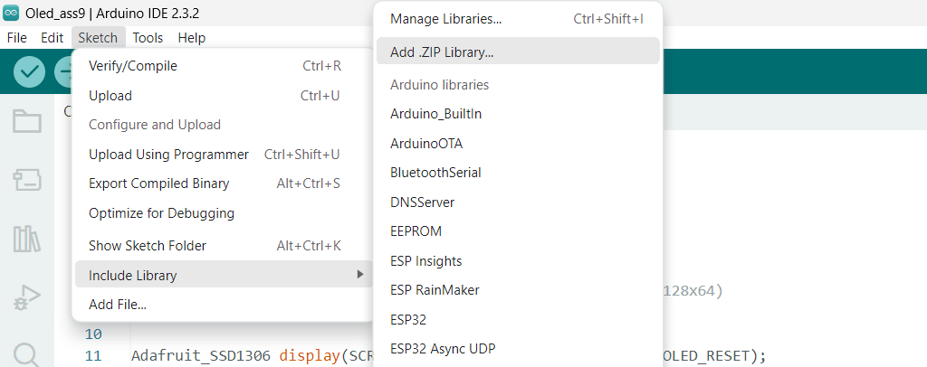
Add library
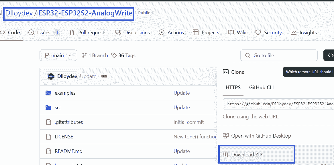
After downloaded zip file added the file in ardino
This library uses ESP32c3 Ardino framework's ledc functions and it provide 16 channels for servos, pwm, leds, buzzers etc.Also include smart GPIO Pin management where pin will attached automatically.
I first kept position 0 to 90 dregree for anticlockwise and then 90 to 0 for clockwise.
Then I change sweep angle to 0-180 for forward and 180-0 for reverse direction.
OLED Display
An OLED (Organic Light-Emitting Diode) is a type of LED (Light-Emitting Diode) that uses an organic compound film to emit light when an electric current passes through it. It's commonly used in devices like TVs, computer monitors, smartphones, and handheld game consoles to create digital displays. There are two main types of OLED: small molecule-based and polymer-based. Read More
SSD1306 OLED Display
SSD1306 OLED Display:
This is a type of display screen that uses OLED (Organic Light Emitting Diode) technology. The SSD1306 is a chip (or IC - Integrated Circuit) that controls how the display works. It's commonly used because it's easy to work with and widely available.
I2C Interface:
I2C stands for "Inter-Integrated Circuit." It's a communication protocol that allows different electronic components, like microcontrollers and sensors, to talk to each other. The SSD1306 OLED display uses I2C to communicate with other devices. This means you only need two wires (pins) to connect it to your microcontroller or other devices, making it simple and efficient.
128x64 Resolution:
This refers to the size of the display screen. It has 128 pixels in width and 64 pixels in height. This resolution determines how much information can be displayed on the screen at once. It's a common size for small displays used in projects like Arduino or Raspberry Pi.
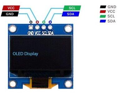
| Terminal | Description |
|---|---|
| VCC | This pin is used to supply power to the display module. It works on 3.3V or 5V power supply input. |
| GND | This pin is connected to the ground (0V) of the power supply. |
| SDA | The Serial Data line (SDA) transfers bidirectional data between the microcontroller and the SSD1306 display. It connects to the SDA pin of the microcontroller or the I2C bus. |
| SCL | The Serial Clock line (SCL) is used for synchronizing the data transfer between the microcontroller and the SSD1306 display. It connects to the SCL pin of the microcontroller or the I2C bus. |
First I checked for the output voltage for VCC,It is 3.1 V
I used above OLED for my board. I have made connections of GND, VCC, SCL, SDA. as I have all this connection in my board. For VCC i have given 3V supply.
Programming
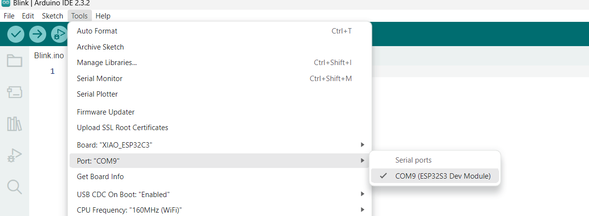
First I open the ardino and then selected board XIAO ESP32C3 and also connect my microcontroller board and selected port for that.
Then I Search for the programmes for OLED display during that I have installed library
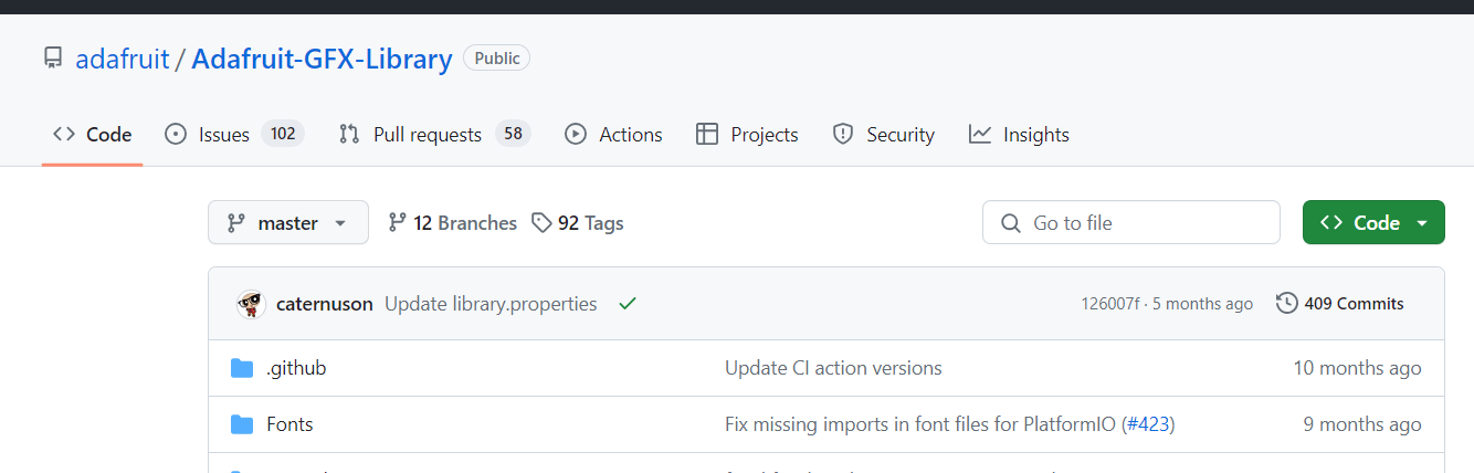
again i installed
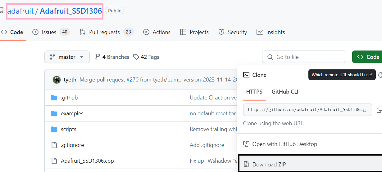
Then added then zip library to program
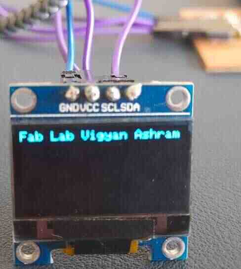
Then start programming by selecting pin and font size and entre name "Vigyan Ashram Fab Lab"
Then I first take font size 1.5
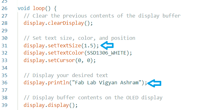
This is my OLED working...
Then I change the font size 2.5
LED
I have connected two led to my board.
Buzzer
Then I connected the the 5V buzzer to my board by using breadboard, and connecting wires to the 5V supply connections on my board. The below image of buzzer I have taken from google
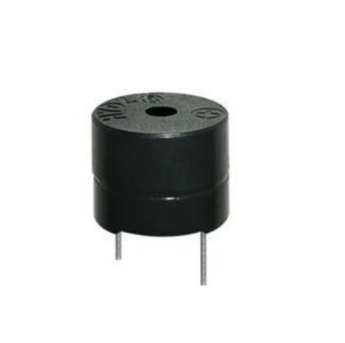
Connections for buzzer is shown in below image one is positive terminal and another is negative terminal. I have connected positive terminal to 5V supply and negative terminal to the ground.

The connections of buzzer with my microcontroller board.
Key Learning
During this assignment I have learned the different output devices. also we have calculated the power consumption and according to that I have connected the output devices like oled display, buzzer, servo motor. For making connection I code in ardino IDE.