Electronics Design
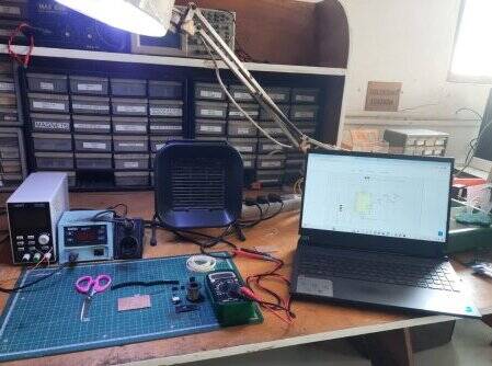
This assignment is about Electronics Design, which includes the basics of electronics, components, circuits, test equipment, and electronic design software for PCB design and simulation. I have used KiCad software for designing PCBs for my own board, along with documenting how I used test equipment to observe the operation of a microcontroller circuit board. Electronics is new to me, including designing PCBs, testing, and all. This assignment has helped me to learn more about electronics. My instructor Mr Suhas has guided me during this assignment and I also tried to clear my concepts by reading from google and i have attached suitable images from google for my understanding.
What is Electronics
Electrons are tiny particles found in atoms, and they are essential for electronics, which involves using electrons to create devices we use daily. Basic electronics includes simple parts that make up these devices, such as resistors, transistors, capacitors, diodes, inductors, and transformers. When these parts are connected in a circuit and powered by a battery, they follow specific physical rules to perform tasks. Basic electronics also includes measuring important factors like voltage, current, and resistance in the circuit to ensure everything functions correctly.
Electronics Working Principle
Electronics work according to a basic rule called Ohm's law. This rule says that in a circuit, the voltage (electrical pressure) is connected to the current (the flow of electrons) and the resistance (the opposition to that flow). Simply put, Ohm's law means that in a circuit with components like resistors and transistors connected to a power source like a battery, the voltage depends on how much current is flowing and how much resistance the components have. So, when making electronic circuits, it is important to follow Ohm's law to ensure everything works properly.Resource Link
Since I am new to electronics, this assignment has helped me learn about different electronic devices, components, and testing equipment. I have written down what I learned below and included links to resources and images of electronic components from Google to help with understanding.
Ribbon Cable
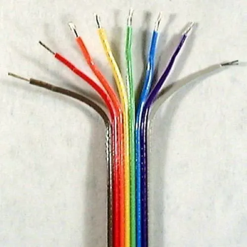
A ribbon cable is a flat, wide cable that contains multiple wires arranged parallel to each other, resembling a ribbon. To help prevent confusion with connections, one side of the cable is typically marked with a red stripe, indicating where it should connect to pin 1 of a connector. While this is effective for cables with several connectors, it becomes less useful for those requiring individual wire termination. To make identification easier, manufacturers produce rainbow ribbon cables, which feature a color scheme similar to the resistor color code (e.g., Brown for pin 1, Red for pin 2). Due to their vibrant appearance, users often refer to these cables as "hippie cables." Resource Link
IDC connector
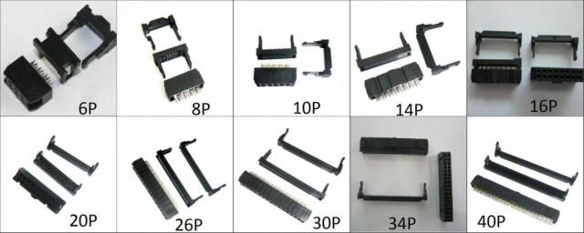
An insulation-displacement contact (IDC), also called insulation-piercing contact (IPC), is a connector for electrical cables. It works by pushing a sharp blade through the cable's insulation to make contact with the conductor inside, without needing to strip the insulation first. This creates a secure connection between the blade and the conductor.
Buttons
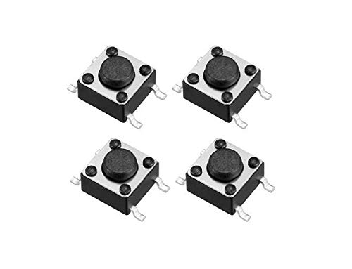
Buttons and switches control things like turning on LEDs or running scripts with just a simple press or flip. No complicated math needed – they just switch between open and closed circuits.
Switch
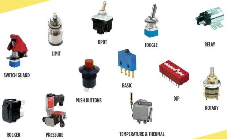
In basic terms, a switch functions as a bridge within an electrical circuit, allowing or halting the flow of electricity. It features a small gate that opens and closes to regulate this flow. We can operate it manually, such as by flipping a light switch, or it can automatically respond to conditions like temperature or pressure, similar to a thermostat. There are various types of switches, including push-button, rotary, and toggle switches. They are utilized in numerous applications, ranging from turning on lights to controlling intricate machinery. In larger circuits, switches must have specialized characteristics to manage high power levels without sustaining damage.Resource Link
Resistor
A resistor is an electronic component that restricts or controls the flow of electric current within a circuit. It can also supply a specific voltage to active devices like transistors. In a direct-current (DC) circuit, assuming all other conditions are constant, the current flowing through a resistor is inversely related to its resistance and directly related to the voltage across it, which is described by Ohm's Law. This principle similarly applies in alternating-current (AC) circuits, provided the resistor does not exhibit inductive or capacitive properties.Resource Link
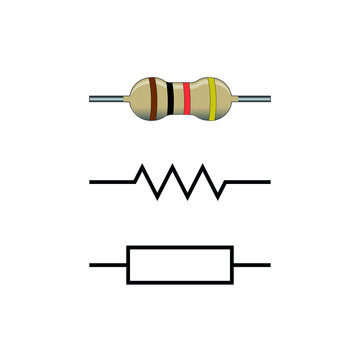
There are two common types of resistors:
Carbon-Composition Resistor:
These are made by mixing fine carbon (like graphite) with clay and then hardening it. The amount of carbon mixed with clay determines the resistance of the resistor. More carbon means less resistance. These are commonly used in electronic devices.
Wirewound Resistor:
This type of resistor is made by winding a wire (often Nichrome) onto an insulating form. Wirewound resistors can handle higher currents compared to carbon-composition resistors of the same size. However, because the wire is wound into a coil, it also acts as an inductor along with resistance. In DC circuits, this isn't a big deal, but in AC circuits, the inductance can cause issues with changes in frequency.
Capacitor
A capacitor is a device in electrical engineering that stores energy by holding charges on two separated surfaces. Once called a condenser, it has two terminals and can come in various shapes. Typically, it consists of two metal plates separated by a non-conductive material known as a dielectric, which helps it hold more charge. Common dielectric materials include glass, ceramic, and plastic film. When voltage is applied, the capacitor creates an electric field, with one plate becoming positively charged and the other negatively charged, without any current flowing through the dielectric. Resource Link
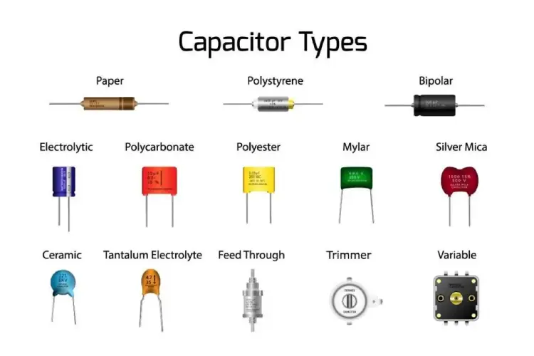
Polarized vs Non-Polarized Capacitor
| Aspect | Polarized Capacitor | Non-Polarized Capacitor |
|---|---|---|
| Directionality | Can only be used in one direction | Can be wired in any direction |
| Common Usage | Power supplies to filter out ripple voltage | Signal coupling to isolate AC voltage |
| Construction | Usually electrolytic, higher capacity in smaller package | Often ceramic, lower capacity per size |
| Replacement | Can be replaced by non-polarized capacitor with same capacitance and equal or higher voltage rating | Can replace polarized capacitors in most cases |
| Advantages | Higher capacity, common in power supplies | Can be used in both AC and DC circuits, lower leakage current |
Crystal
In electronics, we often use a component called a "crystal" to control the timing or frequency of signals. This crystal is usually made of quartz or ceramic and has electrodes attached to it. A more precise name for it is "piezoelectric resonator." We also use crystals in other electronic circuits, like crystal filters, to help manage signals better.
Resonator
A resonator is a device in electronics that creates a specific frequency. It's really stable and resistant to outside interference. Just like in low-frequency circuits, resonators are super important in radio frequency circuits. They're used in things like filters, oscillators, frequency meters, and adjustable amplifiers. The ones we often use in radio frequency and microwave circuits are mostly transmission line resonators
Transister
Transistor is like a tiny switch that can control the flow of electricity. It's made of a special material called a semiconductor. This material can either let electricity flow through it or stop it, depending on how we control it.A transistor typically has three parts where we connect wires. These parts are like the entry and exit points for electricity. By sending a small electrical signal to one part, we can control whether electricity flows through the other parts or not.So, in simple terms, a transistor helps in controlling and amplifying electrical signals in electronic devices like computers, phones, and TVs.
BJT vs MOSFET
| Aspect | BJT (Bipolar Junction Transistor) | MOSFET (Metal Oxide Semiconductor Field-Effect Transistor) |
|---|---|---|
| Type of Transistor | 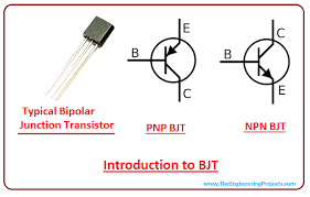 |
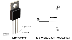 |
| Terminals | Base, Emitter, Collector | Source, Drain, Gate |
| Applications | Low current | High power |
| Popularity | Less common nowadays | More common nowadays |
| Control Mechanism | Controlled by current at the base terminal | Controlled by voltage at the gate electrode |
| Control Type | Current-controlled device | Voltage-controlled device |
| Usage | Less frequent | More frequent |
| Structure | Simple structure | Complex structure |
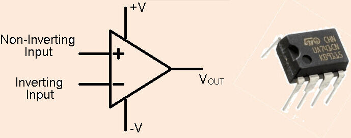
Op-amp
An operational amplifier is an integrated circuit that can amplify weak electric signals.
An operational amplifier consists of two input terminals and a single output terminal. Its basic role is
to amplify and output the voltage difference between the two input pins.The op amp is one type of differential
amplifier.There are other types of differential amplifiers, each with its own special features and uses.features of amplifier:
Voltage Amplifier: It takes in electrical signals and makes them stronger.
Differential Input: It has two input terminals where you can put in different voltages.
Single-Ended Output: It gives you one output voltage that's usually higher than the inputs.
High Gain: It can boost signals a lot, making them much bigger.
Negative Feedback: This clever trick helps control the op amp's behavior using external parts. It keeps things stable and predictable.
Temperature and Tolerance: Its performance isn't too affected by changes in temperature or manufacturing differences.
Resource Link
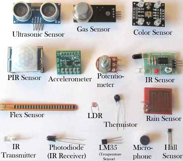
Sensors
Electrical sensors, also known as electronic sensors, are devices that detect physical properties like heat, light, or sound, and convert them into electrical signals. These signals can be measured and used by electronic systems. The primary purpose of sensors is to measure the physical environment and trigger appropriate responses based on those measurements. For example, if we want to gauge the temperature we use temperature sensor and produce an electrical signal representing that measurement, which can then be used to activate systems like heaters or air conditioners. digital processors often handle the signals from sensors, but before that, the continuous analog signals must be converted into digital form using Analog-to-Digital converters. Sensors come in various types capable of detecting and measuring different physical quantities such as light, pressure, speed, acceleration, and mass. Depending on the application, the size and characteristics of the electrical signals produced by sensors can vary according to their use.
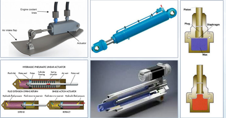
Actuators
An actuator is like a mover in a machine. It takes in signals like electricity, air pressure, or fluid pressure and turns them into movement, force, or twisting power. It is like the part of a machine that gets things going when you push a button or flip a switch.There are different kinds of actuators. Some move in a straight line, like pushing or pulling, while others twist or turn. They can be powered by electricity, air, or fluid.Actuators need a control device, which tells them what to do, and a power source, like electricity or air pressure. They help automate machines, making them work without needing constant human input. There are two main types of actuators: ones that move in small, fixed steps and ones that move smoothly and continuously. e.g. stepper motors for small steps and e.g. hydraulic motors for smooth, continuous movement.
Voltage and Current
| Parameters | Voltage | Current |
|---|---|---|
| Definition | Voltage is the potential difference between two points in an electric field, which causes current to flow in the circuit. | Current is the rate of flow of electrons is called current. |
| Symbol | Voltage is represented by “V” | Current is represented by “I” |
| Unit | Volt “V” | Ampere “A” |
| Unit Charge | 1 Joule / Coulomb = 1 Volt | 1 Coulomb / Second = 1 Ampere |
| Formula | V = W / Q | I = Q / t |
| Measuring Instrument | To measure the value of voltage by connecting it in parallel we use voltmeter. | To measure the value of current by connecting in series we use ampere meter. |
| Types | Alternating Voltage and Direct Voltage | Alternating Current (AC) and Direct Current (DC) |
| Field Produced | Magnetic Field | Electric Field (Electrostatic) |
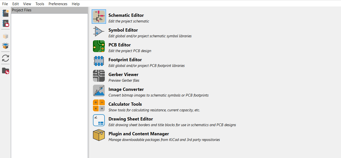
Kicad
Kicad is the PCB design software which I have explored for this week to design my own circuit. The steps for design in kicad are as below.
Install Kicad from google

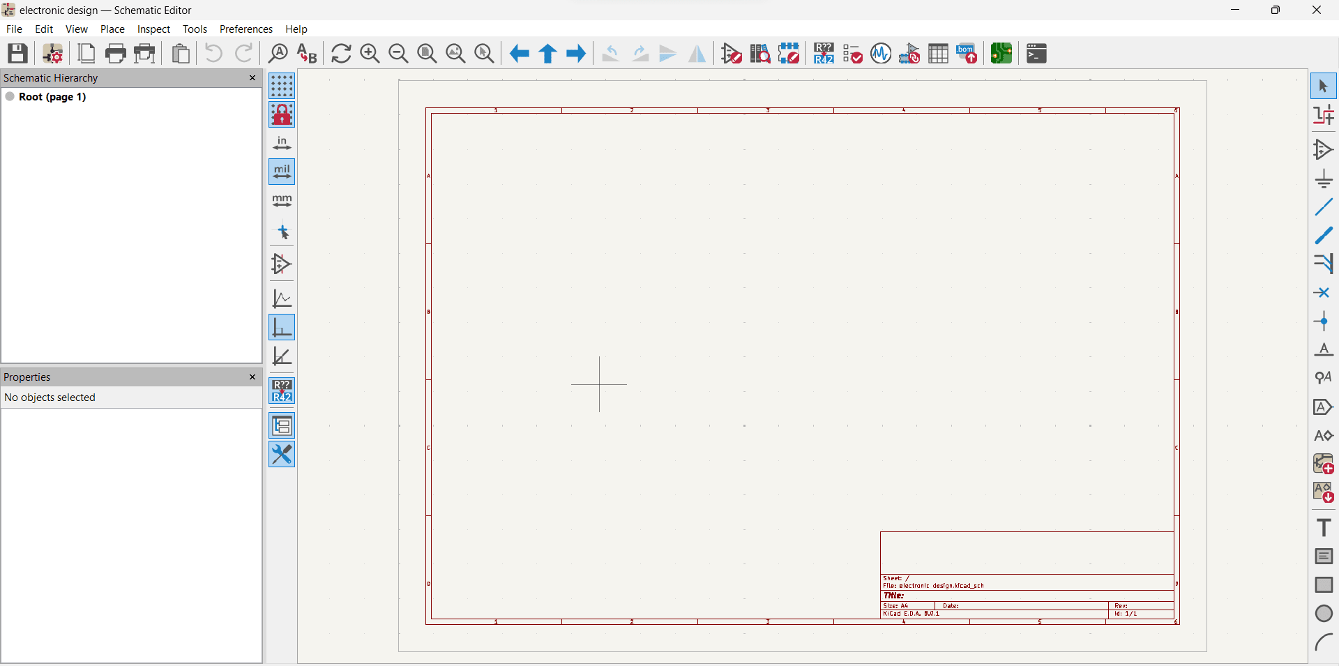
Open and explore tools in kicad one by one Kicad interface look like....
First create new project and save the file.

Then In Project two files are created
1. Electronic Design Kicad_pcb
2. Electronic design.kicad_sch
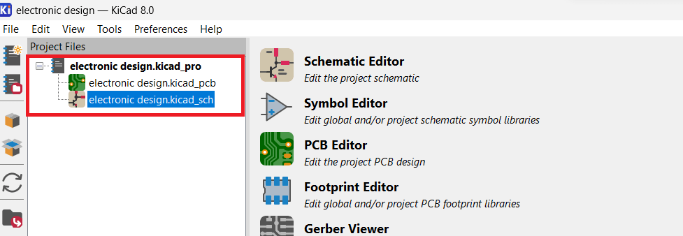
First do the Electronic schematic design by selecting the Electronic design.kicad_sch
Then I search for library on google.

Downloaded the zip file and Extract the zip file in desired drive folder.

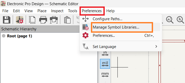
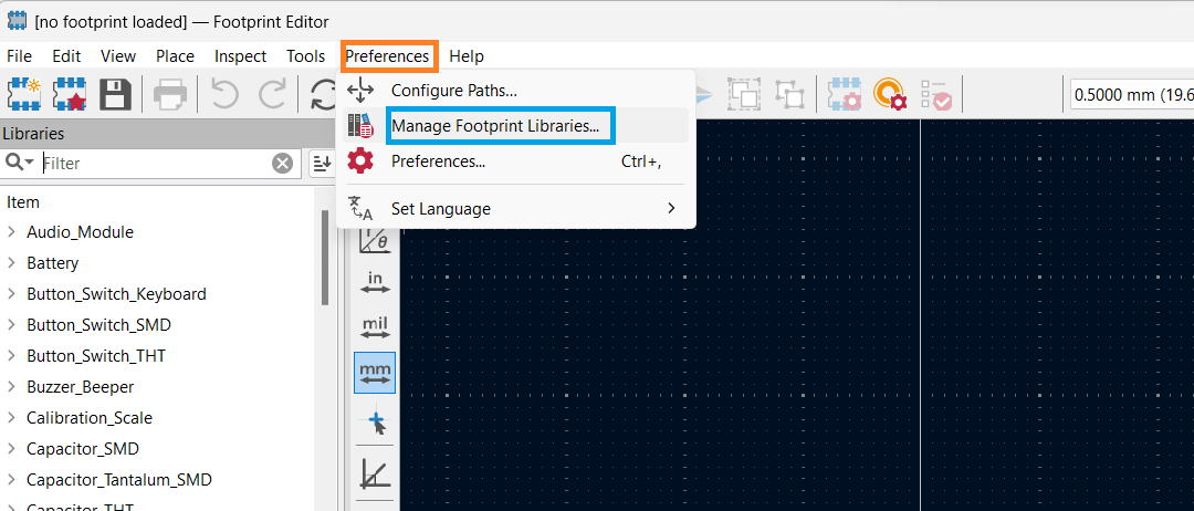
Then go to preferences and then click manage symbol library.
Add existing Library to table
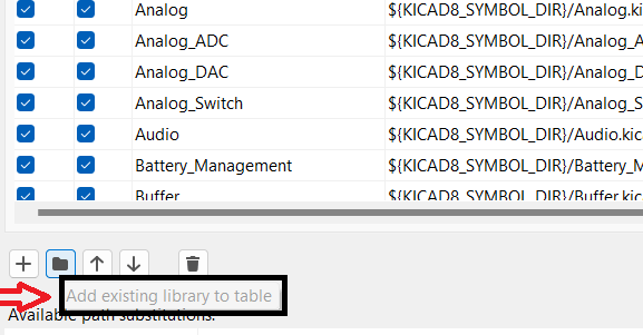
Add fab.kicad_sym as symbol library.

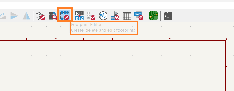
Go to Footprint editor.
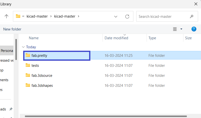
Go to " Manage Footprint Libraries" in Preferences and add fab.pretty as footprint library.
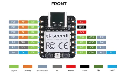
Then I added symbol and search for RP2040 EVA board and clicked Ok
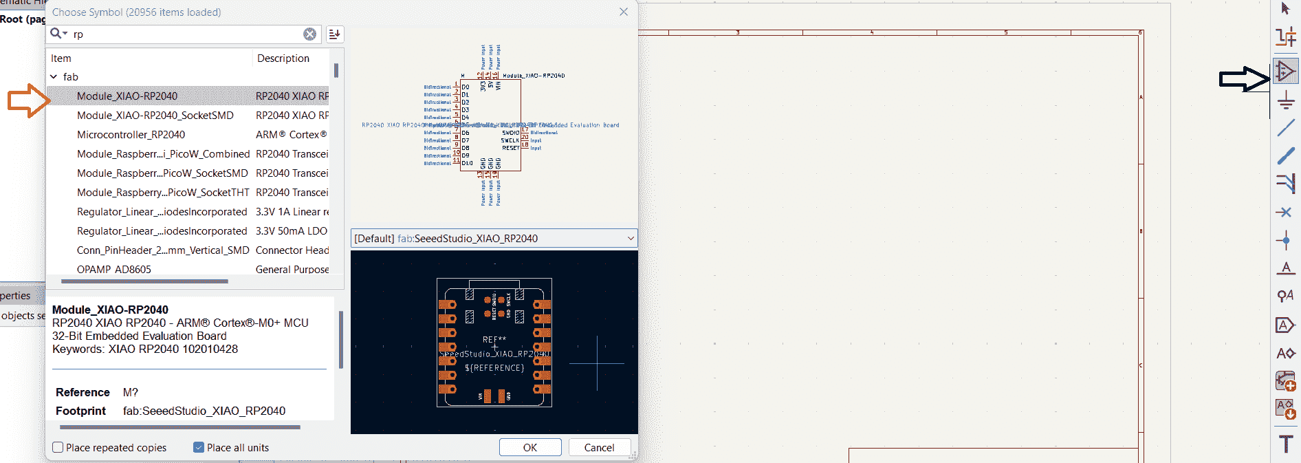
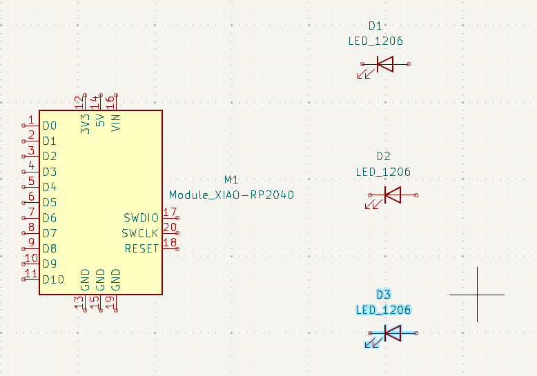
I got RP2040 in my schematic design sheet.Then I took LED from librabry
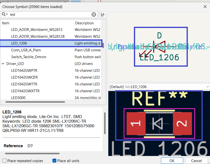
I took three led_1206
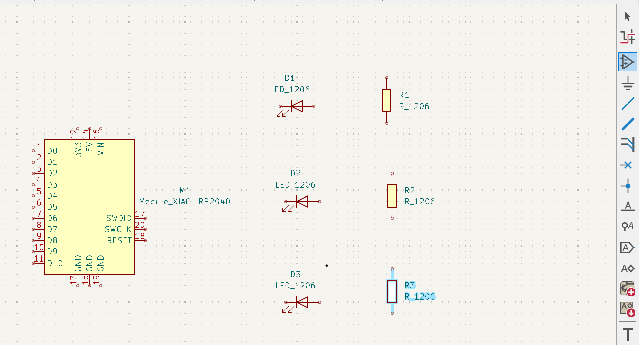
For LED important is to connect with resister so i took three resister 1206
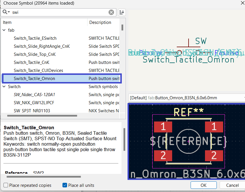
Then I added one push button.
Use wire to connect LED, resister and other components.
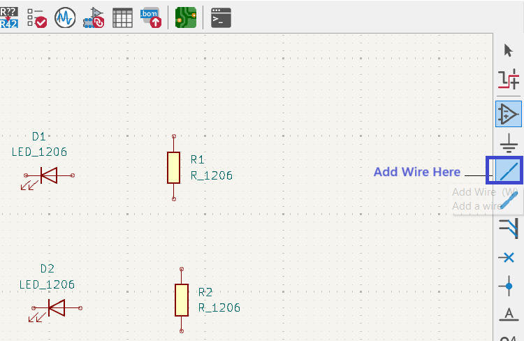
Refered diagram for connections & document Read More
I have first made the Schematic diagram like below..In which I done wrong connections for led,resister and pins and complex to understand.For the mistakes I have made for connection of led, Suhas sir guided me for the connections.
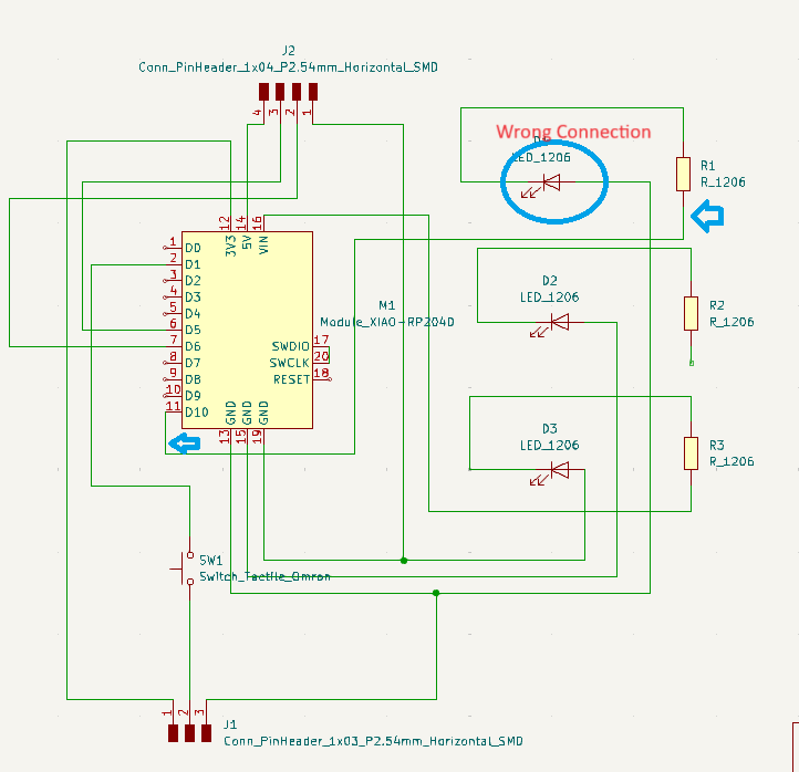
Establishing proper positive and ground connections is essential. Afterward, I created a schematic diagram on the page and repeated the procedure. Once I understood the pin connections, I utilized wires to construct the circuit diagram.
Schematic diagram I have made in Kicad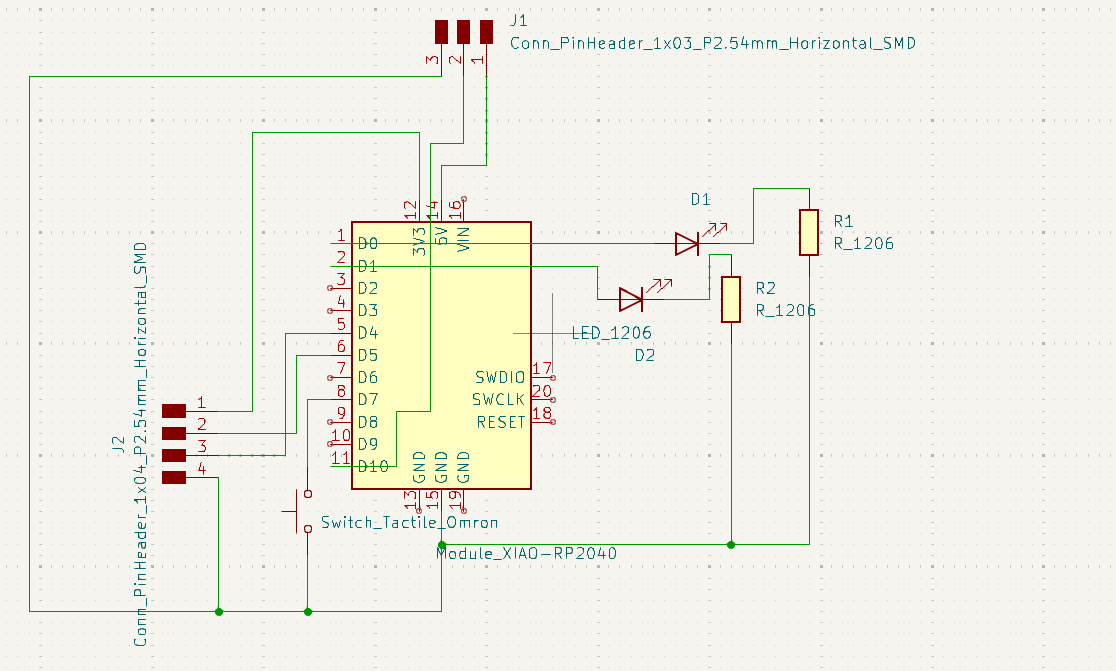
After completing the scematic diagram we have go to PCB editor.There are two ways to go at PCB editor interface
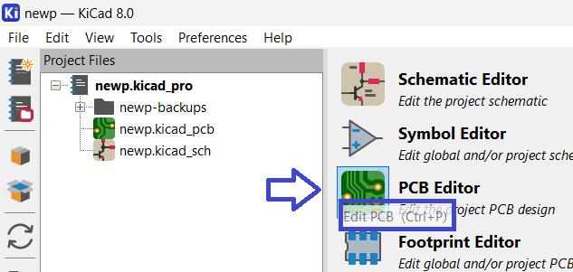
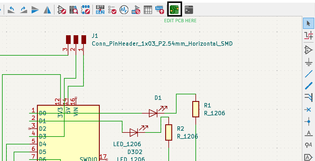
Then Go to tools and update PCB from schematic

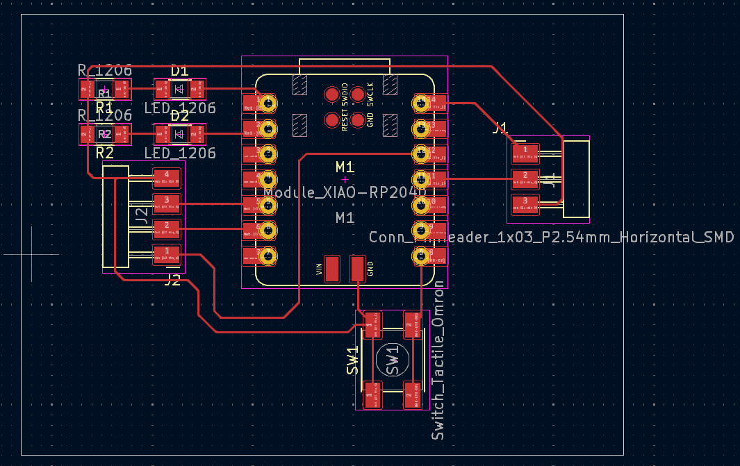
Check the connections and manage the components according to their pin positions. Try to minimize crossing lines and place the components as close to their connections as possible, without touching each other, leaving necessary space to reduce congestion and do the routing and give the outer cut like square or whatever you want.
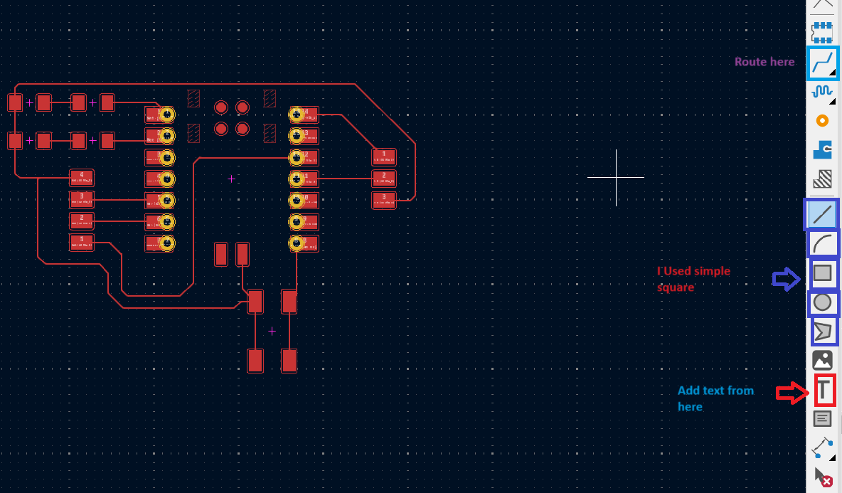
Routing for my PCB
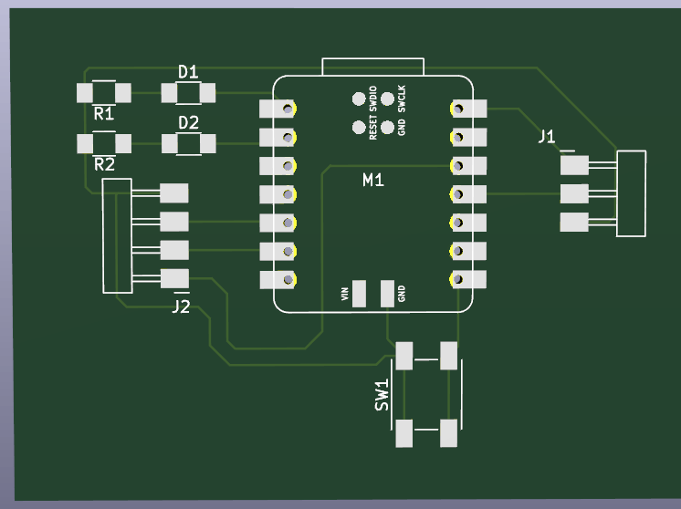
3D View of my PCB
After checking all the next task is to save the file in SVG file format.
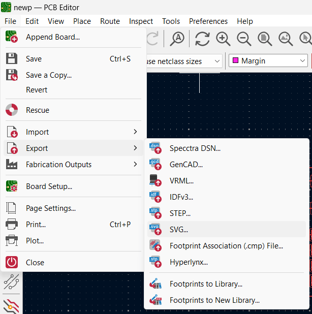
Now the files has been ready for Mods CE to convert SVG to RML file format.

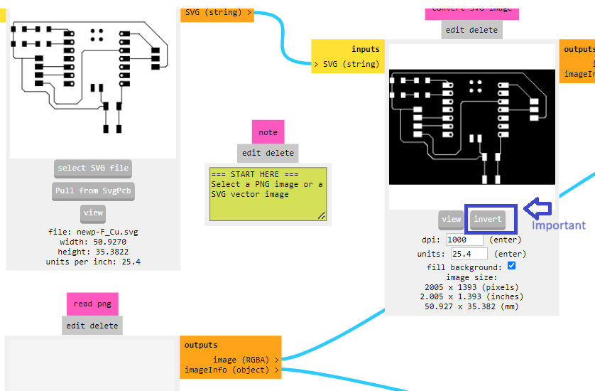
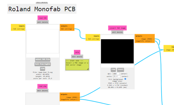
As we have done in Production week, In this week also we have to use MODs software for convert the SVG file into rml. All procesure is same as previous assignment. here only additional thing is to invert the svg file is new and important.
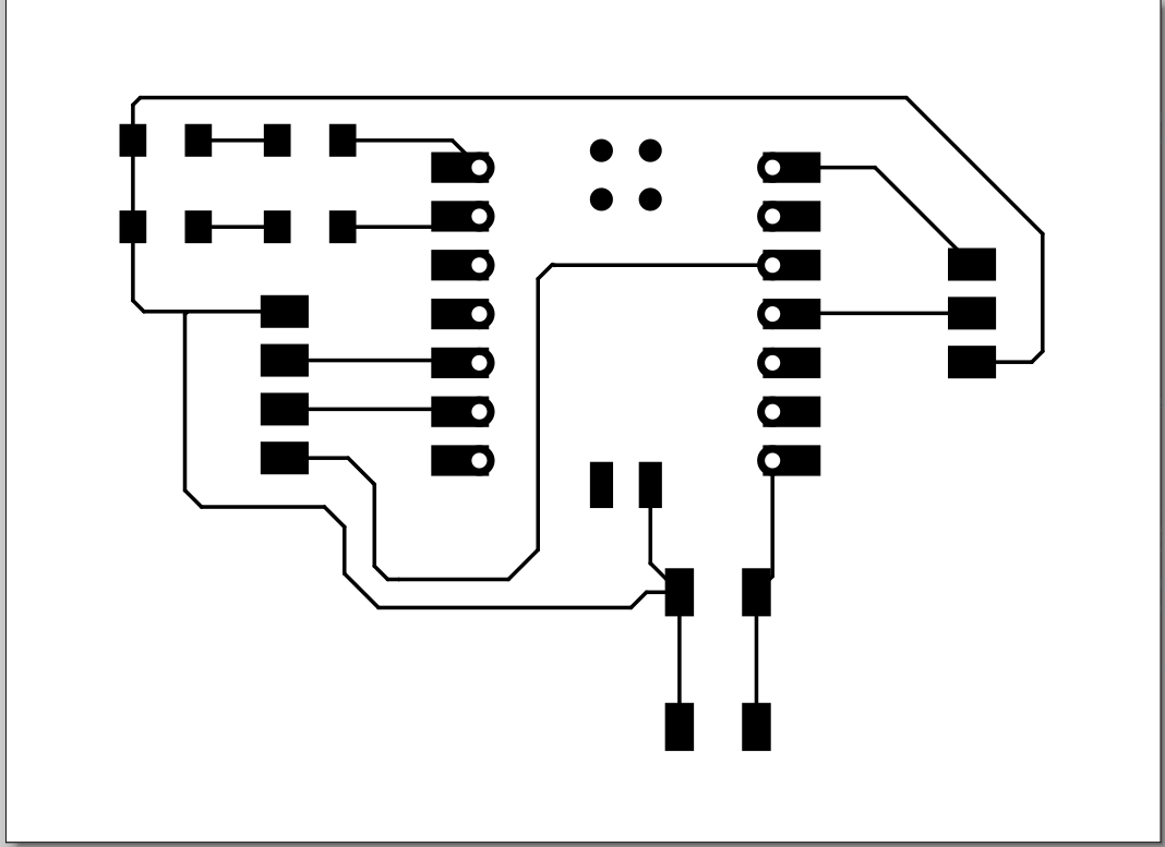
Trace file for my board
Border file for board
The first time I attempted milling, my traces weren't proper. There was a problem with milling the border trace file—it was milled properly, but during the milling of the border file, it overlapped with some parts of the trace.
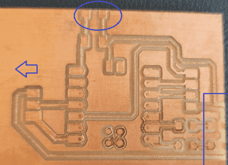
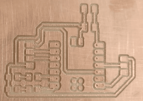
Then I increse the distance between trace and border then mill the PCB.
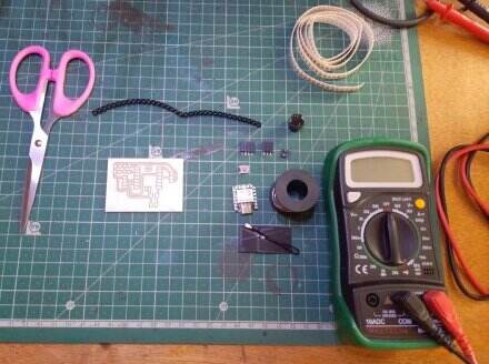
Then I go for the soldering. Collected all components like led,resister, Connector microcontroller which is ESP32C3,I have milled the schematic for Xiao RP2040 but the we decided to solder ESP32C3 because found the pin connection for both are same.
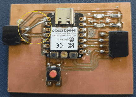
I am done with the soldering my PCB but in my PCB LED is not working. then I done trial and errors for resolve this issue.
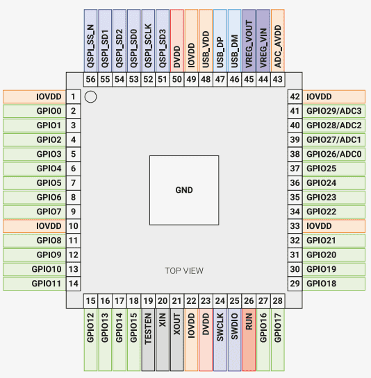
Then I found whats the problem.First during schematic and designing I have used RP2040 microcontroller board. During soldering I have change the board and take ESP32C3 microcontroller board.
Pin connections for both two boards are same but different ground connection so I have problem for making connections my LED are not glowing. Then, by doing trial and error, with the help of my colleague Shankar and Soham, I managed to solve this problem. I have connected ground connection externally by soldering the metal wire from 3 pin ground to board ground.
My new schematic diagram
Here I found that my ground connection is not done. I have not check ground connections before soldering only check the pin connections.thats the reason for my problem to LED blink program not working.So I solder metal wire and made ground connection.
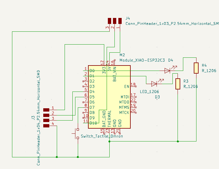
In My PCB I can Connect SG90 Micro Servo as I have 3 pin connector.I am going to make connection one to 5V supply where I Can Connect Speaker, Servo Motor, Led, RGB, and one to 3.3V where I can connect OLED display.
Key Learning
In this assignment I learn about how make our own design for PCB by using KICAD
Learned about the tools in Kicad for making Circuit diagram.
When designing, it is important to properly connect the positive and negative (ground) terminals of components. Additionally,
while milling the PCB, you need to know how to use MODs software to invert the SVG file for proper cutting.
This Assignment teach me about the file formats like SVG,RML and how to convert that files.