Interface And Application Programming
This week assignment is Interface and Application Programming.
Group Assignment
Evaluate a wide range of tool options available.
Record your findings on the group work page and reflect our personal page about learning experience.
Please find Group Assignment Link Here...For Group Assignment Click Here
Individual Assignment
For this week assignment my instructor said me to explore MIT App Inventor. so I started to go throgh from previous student assignments and refer Hrushab assignment for this week.
First Open the website for MIT App Inventor. Click for link
Hero Shot for this week
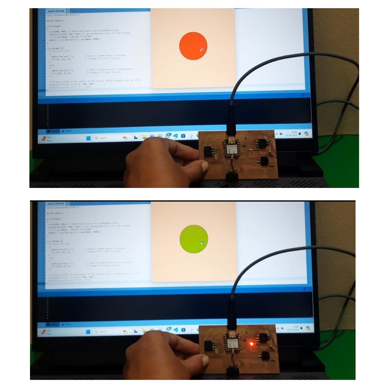
Hero vedio for this week
For creating a applications first sign in google account and follow the steps are given below...
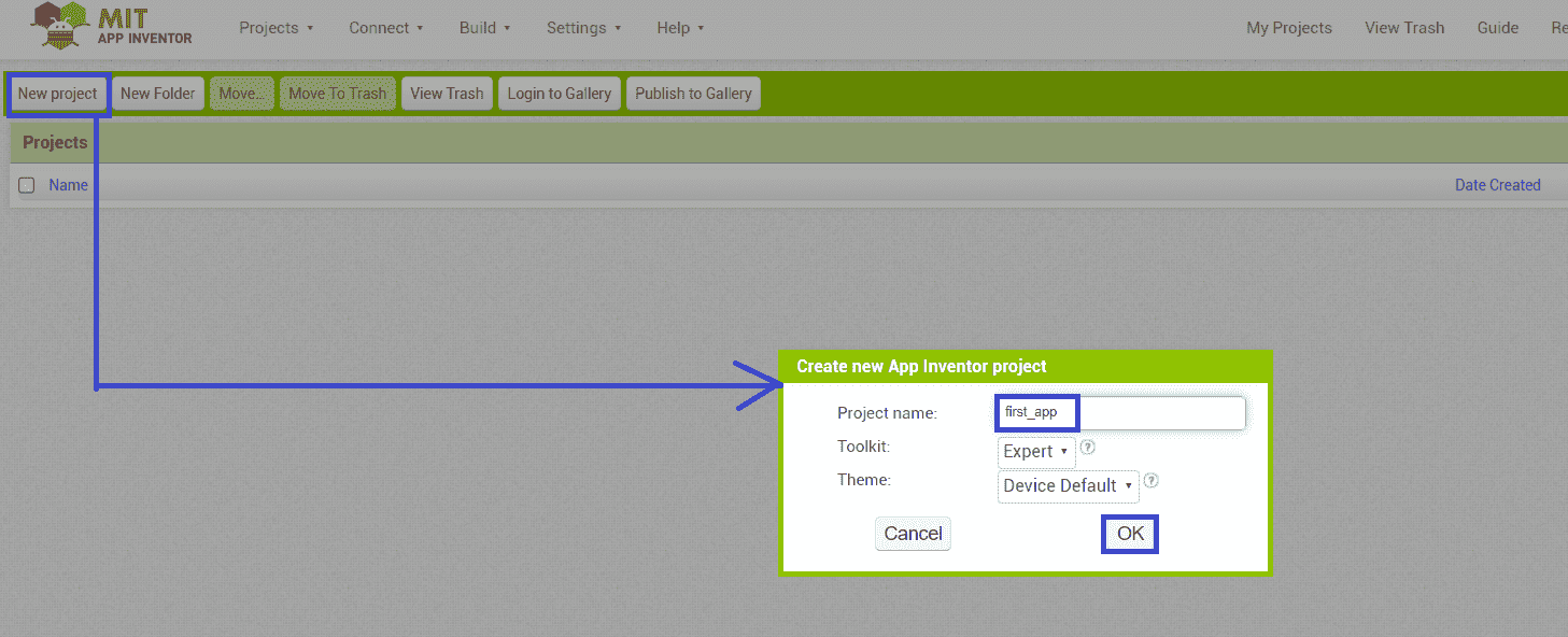
Cick on the "Create App" button

Then click on the new project & Create New Project
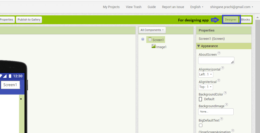
Designer for designing application
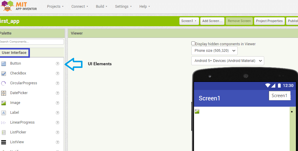
In the MIT app inventor interface there is designer that allows us to design an application.In that we can add buttons or any UI elements.
Designer section
UI elements in palette
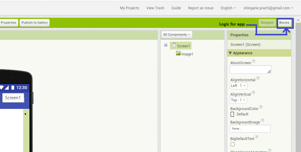
Block Section
Block section builds logic for application for movement or on/off the output devices.
Design App
Add layout
First add the layout for horizontal arrangements by drag and drop the element to the screen that element is added at right side in components under screen.
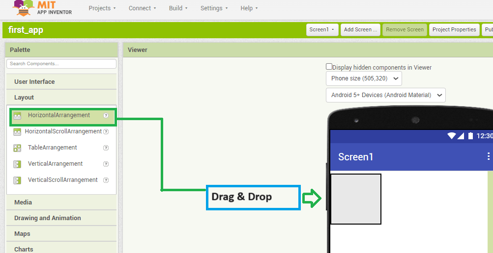
Select Horizontal arrangements
After selecting the horizontal arrangements there open properties setting next to components.
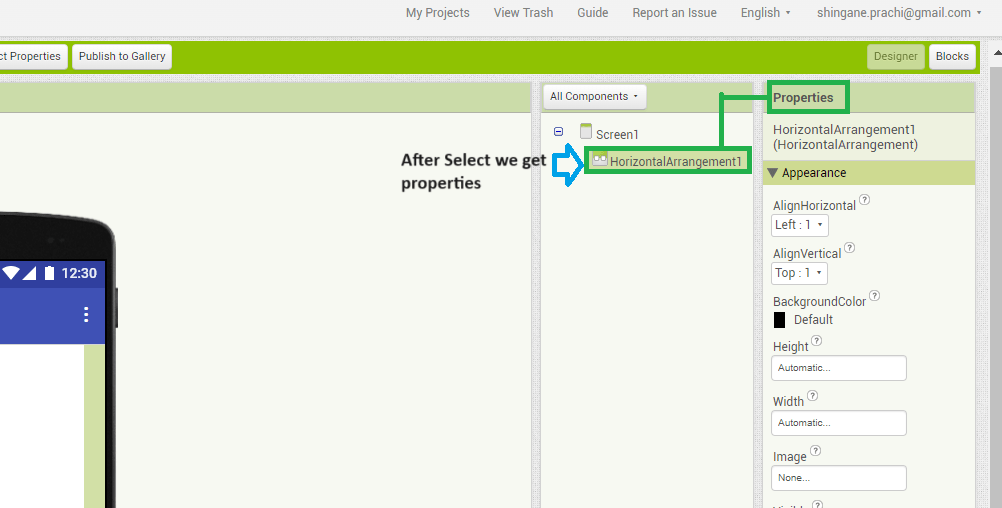
Properties
Here we can customize the application like change background color, size.
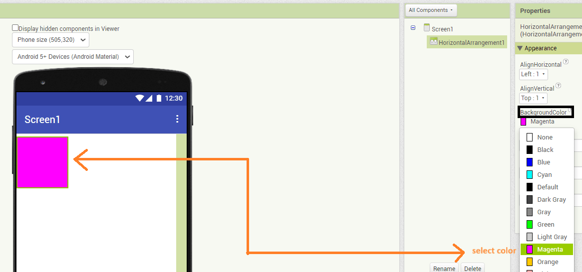
Change background color
In properties I clicked on "BackgroundColor" and selected magenta colour.
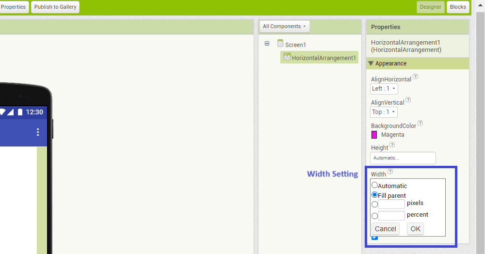
Size of screen
Here I Set width and height. First clicked on the width and select "Fill parent" and clicked OK.
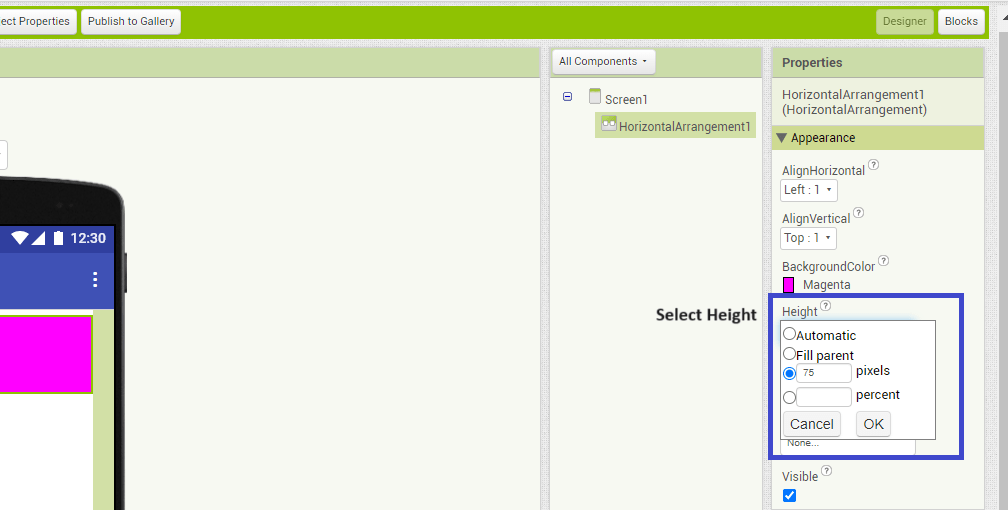
For height I selected 75 pixels and selected OK.
Add ON/OFF Button
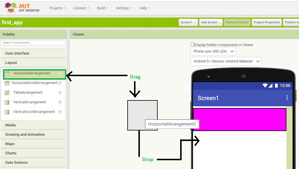
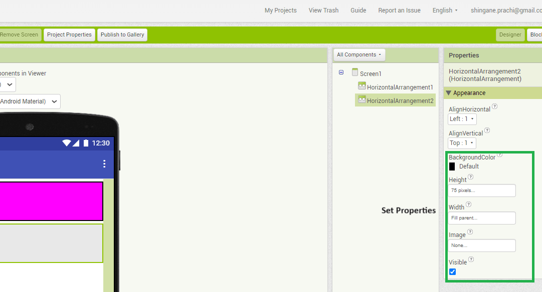
For adding on and off button we again drag and drop the horizontal arrangenent and set properties.
Drag and Drop horizontal arrangement
Set properties
I put height 75 pixel, width fill parent and background color as default.
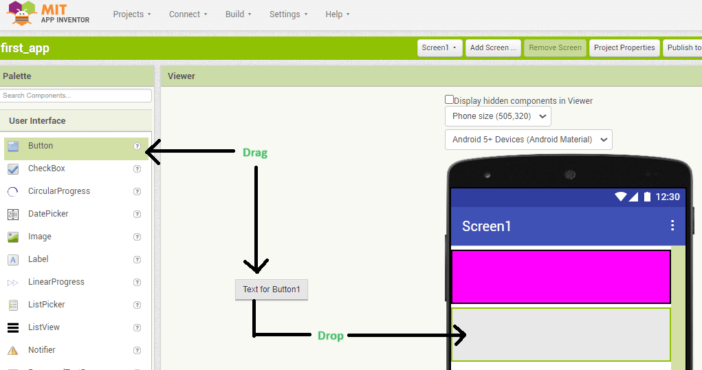
Add buttons
From user interface I am going to add two buttons.
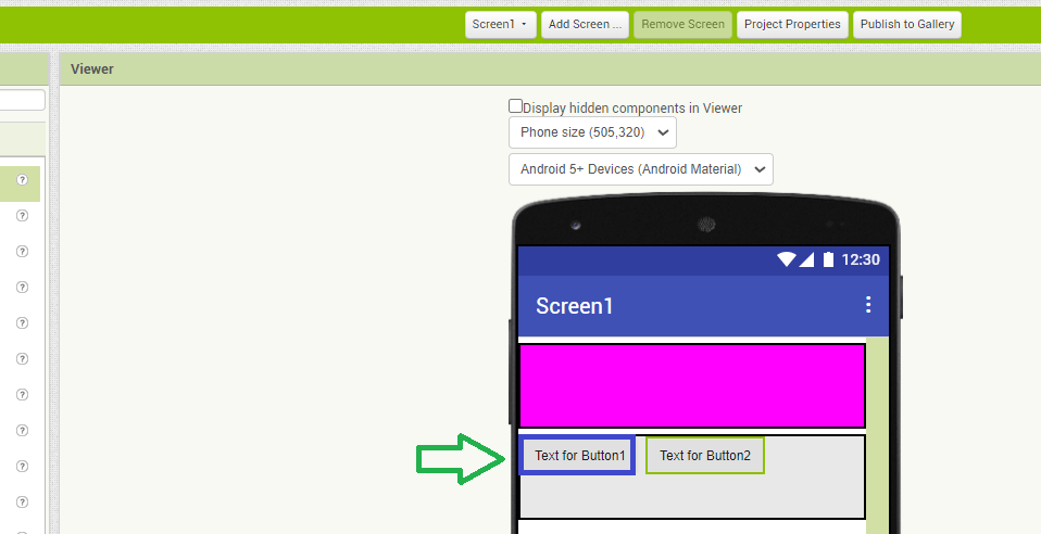
Similarly, added one more.
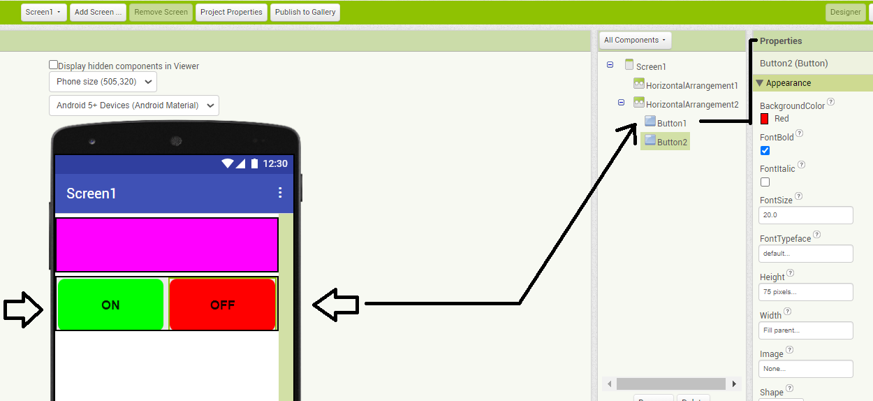
set properties for buttons
Connection Part
For connection drag and drop listpicker.
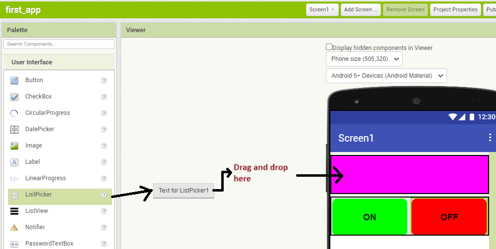
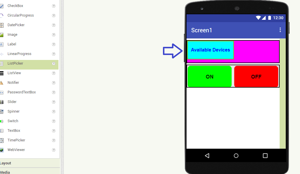
Rename the listpicker name with Available devices.
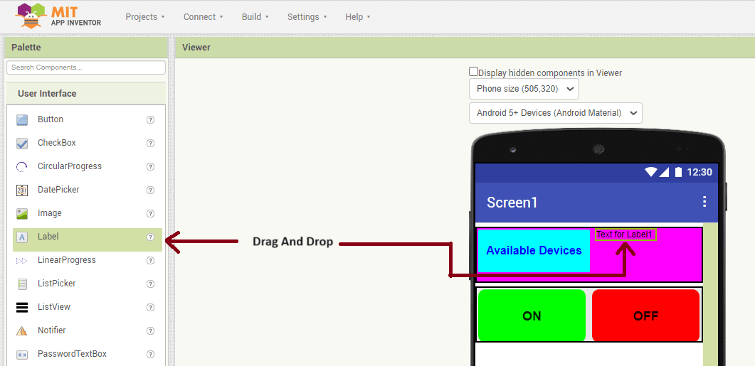
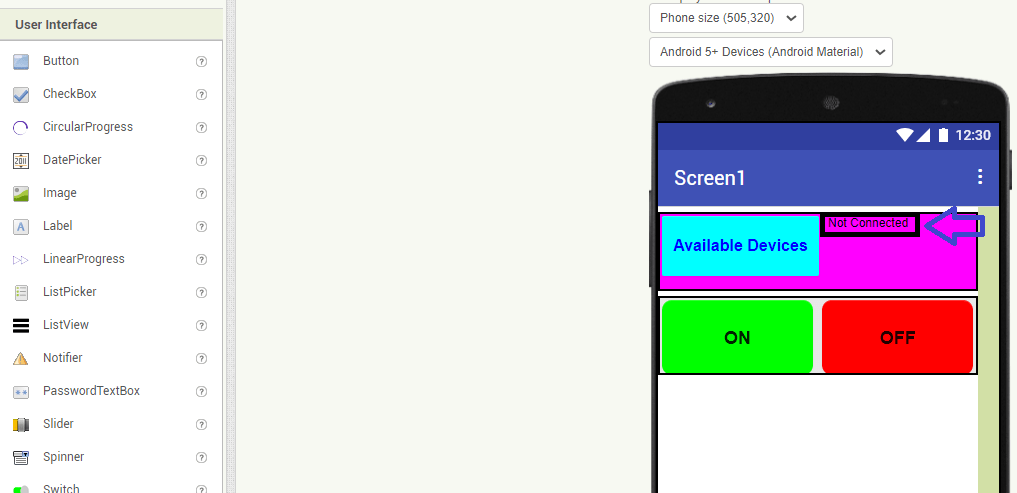
Drag and drop the lebel and rename it as "Not Connected"
Build Logic For App
For blutooth device connectivity we required other component is connectivity. for this steps are below.
Select "BluetoothClient" in connectivity.
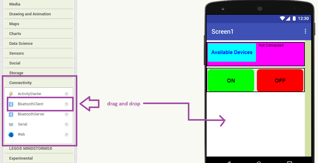
drag and drop the blutoothclient below buttons.It is non visible component.
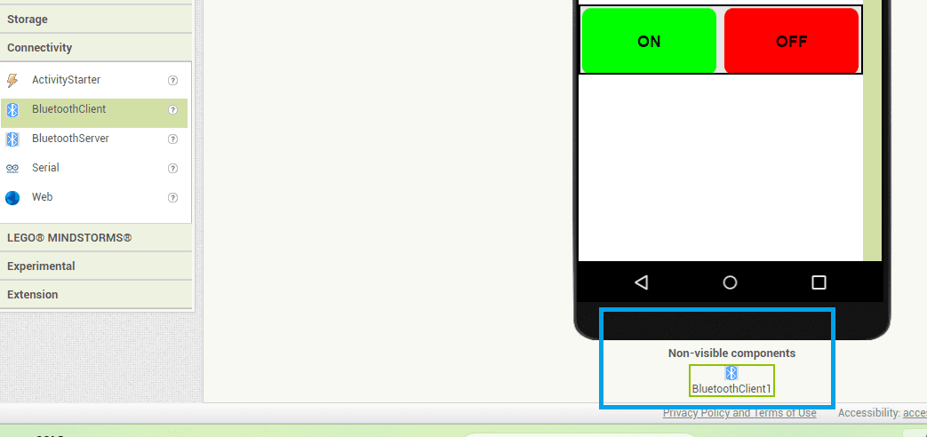
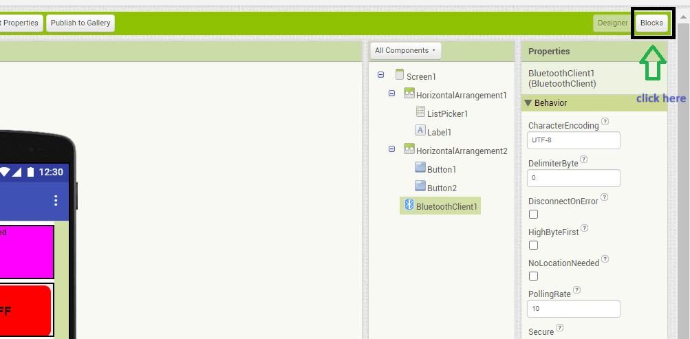
Then I Clicked on block section.
In blocks select bluetoothclient and in that select addresses and names.
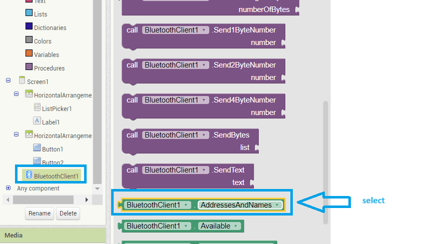
drag and drop above addresses and names block then select listpicker and in that select before picking block.this is an event.
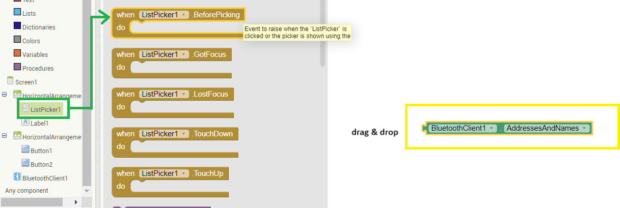
For display names and address we again required block of listpicker elements.
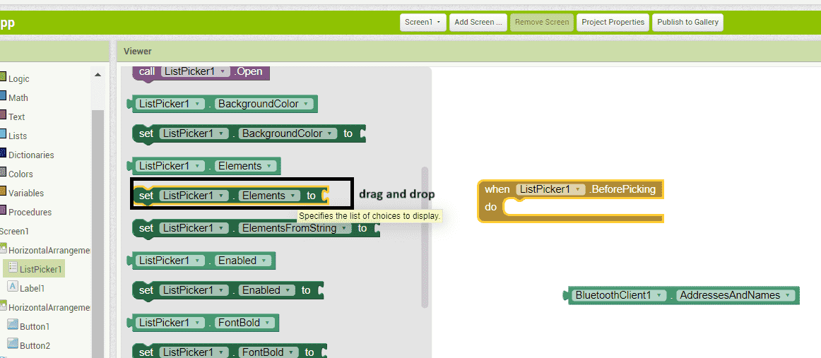
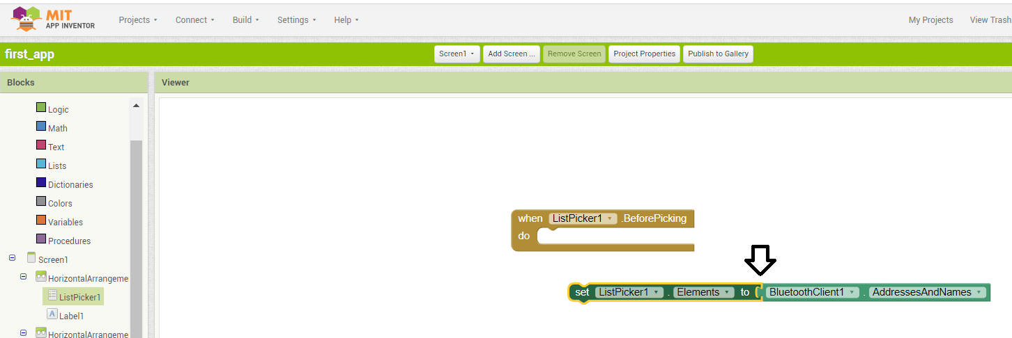
connect listpicker addresses and names block with listpicker element.
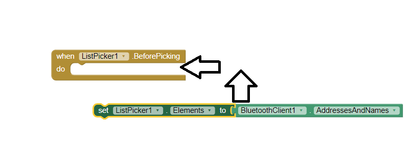
connect above connected block to listpicker before picking.
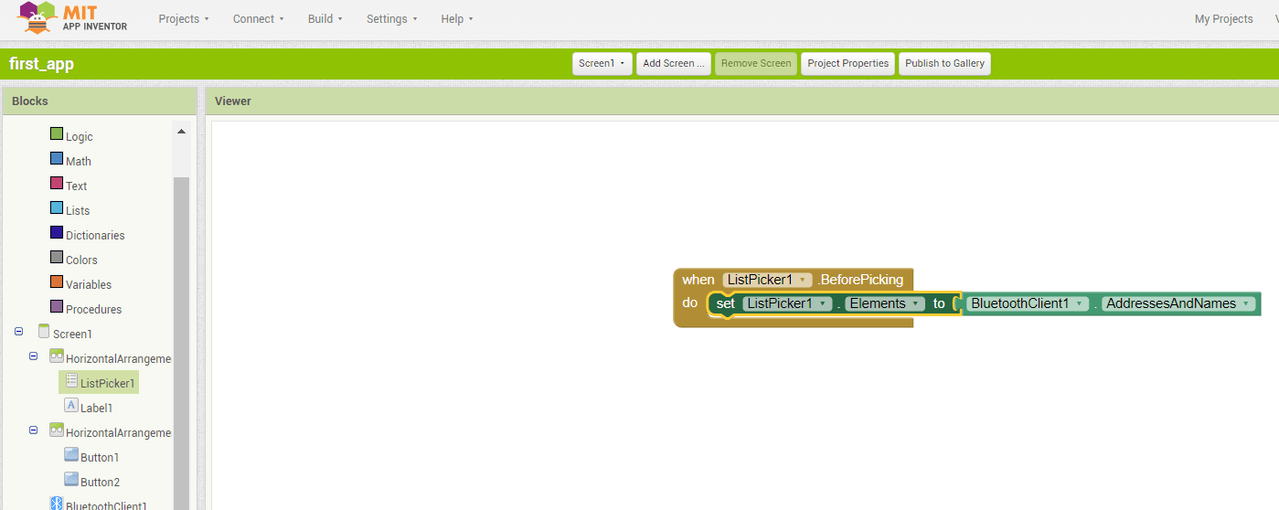
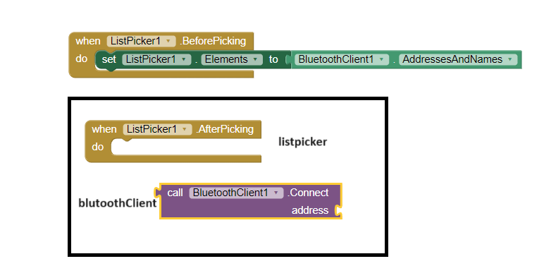
Then similarly, I pick listpicker after picking and bluetooth client component connect address
Then pick listpicker-selection block and put it inside the afterpicking event. but for here we have to make logic for connections is it true or false.
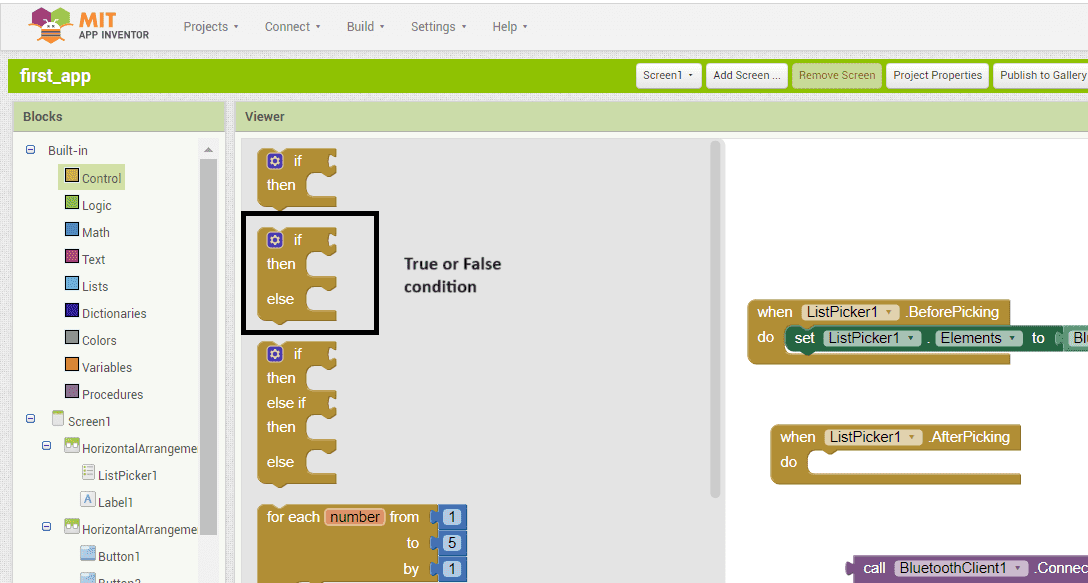
For this we have to add logic under the control section. Here I used "if else statement" and put it inside After picking.
Then put connect address block inside afterpicking near if condition.
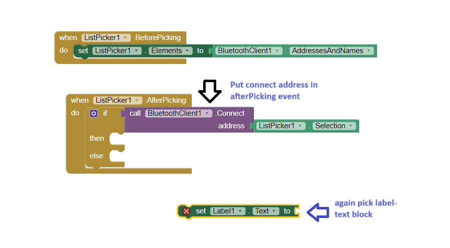
Then again select lebel - text. Then put it inside afterpicking then condition and take block for connection from built-in in that select text and select first one for string and put it infront of label-text block and type connected.
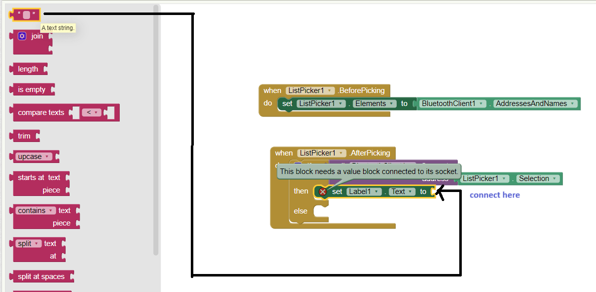
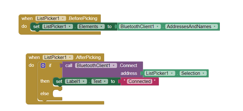
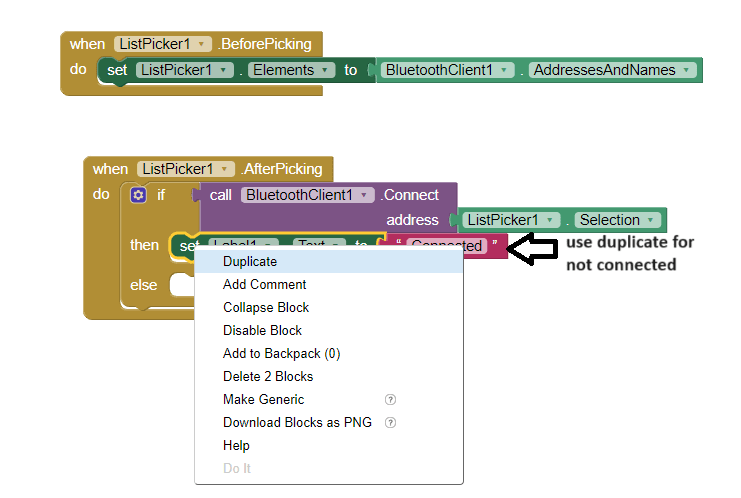
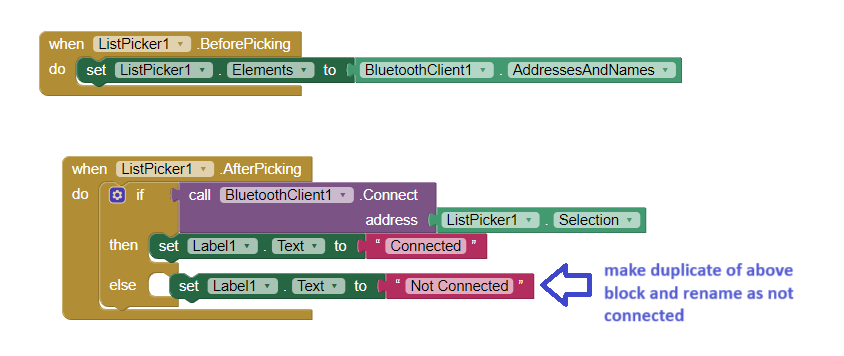
Then make duplicate for above block and rename it as "not connected"
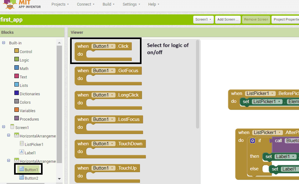
Then click on Button1 in that select when condition block and then select send_text from bluetoothClient and drag in the text block and simply type 1.
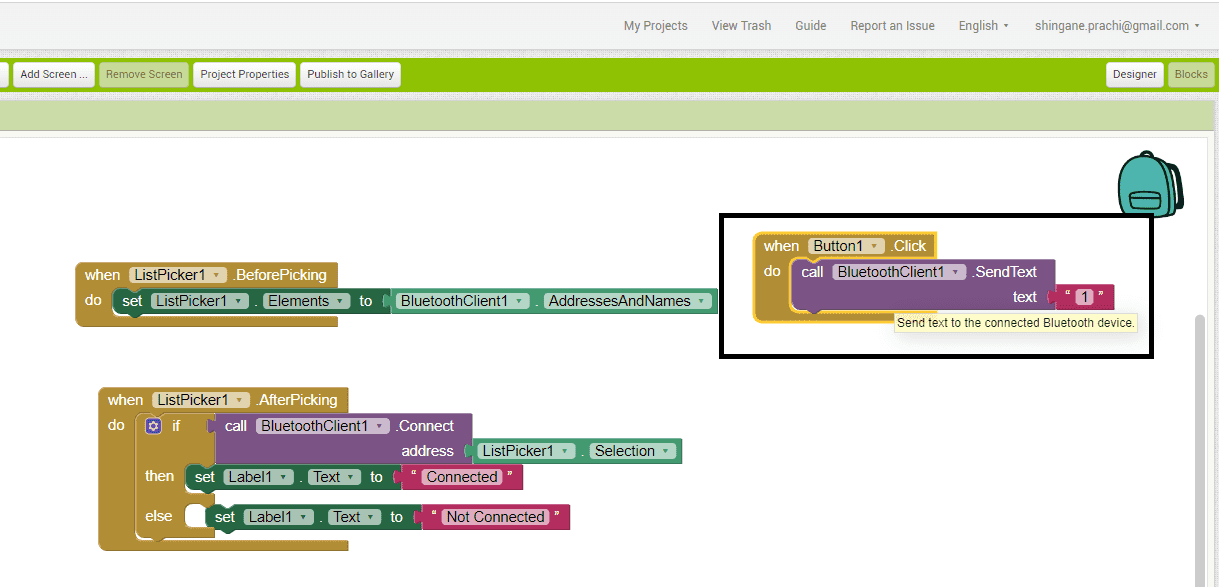
now use if clause for the reason, If bluetooth client is connected then bluetooth client can send massage 1.all these done by activate the event click.
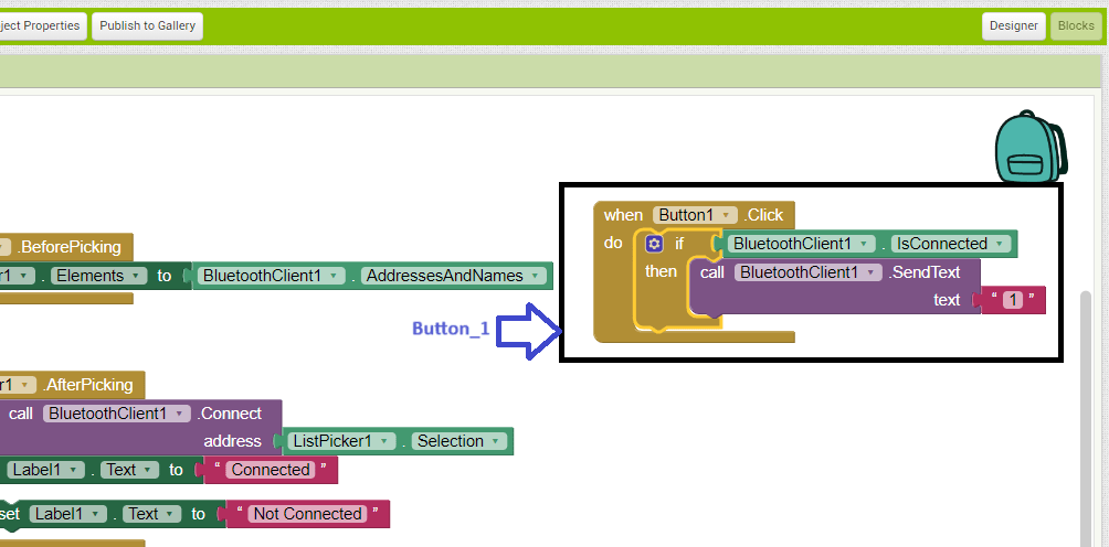
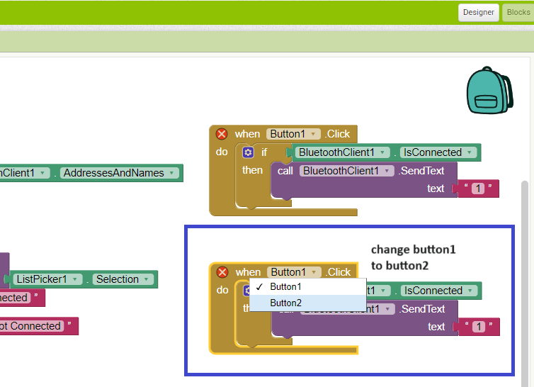
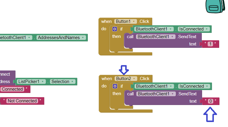
now I want to create second button so I duplicate the above block rather than drag and drop.
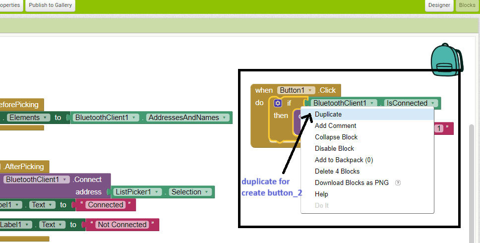
Here change the Button1 to Button2
And change the number 1 to 0 for off the button.
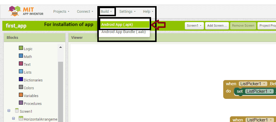
Now my app is ready.Now for installing this app we need APK file.For this use build function.
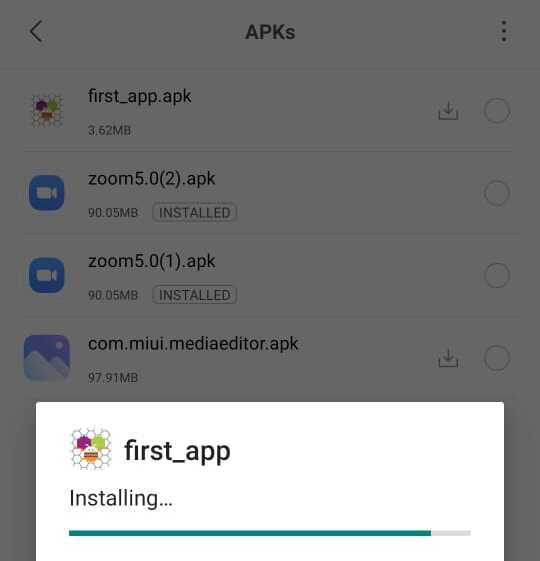
Then after that I took that file in my mobile and install the app.
Then I turned on the bluetooth and trying to pair my ESP32c3 board with my application but there is some problem to connect that esp32 bluetooth. So I decide to connect connect ardino uno board with bluetooth module HC-05.
My first apllication for on/off the led on Ardino UNo is successful.
Communication Between ESP32C3, Arduino and Processing
Processing
Processing is an open-source software platform similar to the Arduino IDE. It allows for communication between the Arduino IDE and Processing, enabling users to send and receive data between the two. This integration allows users to display the output of Arduino programs within Processing and connect the ESP32C3 through the Arduino IDE to perform desired operations. Additionally, Processing provides a canvas where users can create designs and control various elements, functioning similarly to a remote interface, allowing users to specify and manage different aspects of their projects.
The following steps outline my approach to establishing network communication between Processing and the Arduino IDE using my custom-designed ESP32C3 microcontroller board during the input assignment week.
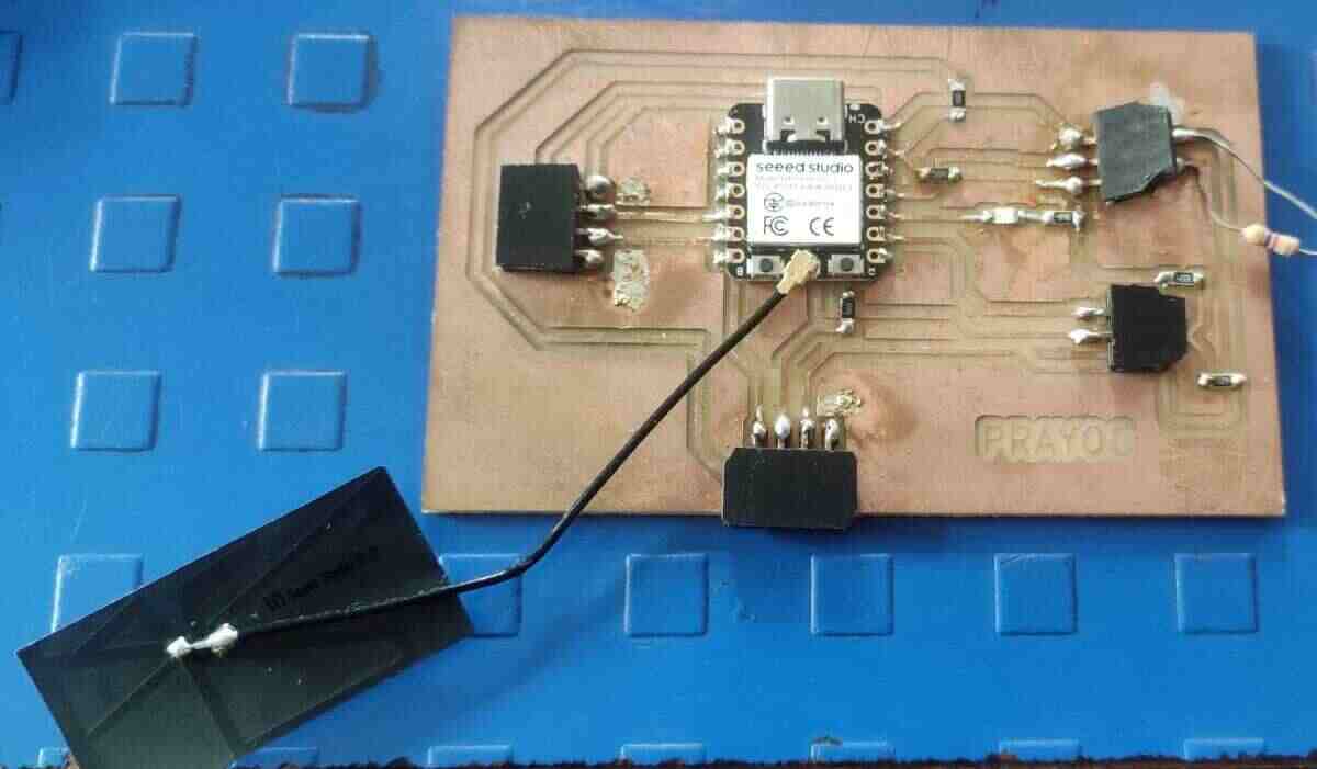
To view the design and milling process of the board, please click on the link next. Click Link Here
Step 1: Started by downloading Processing from Google and then extract all files.
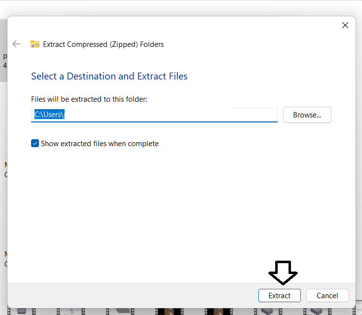
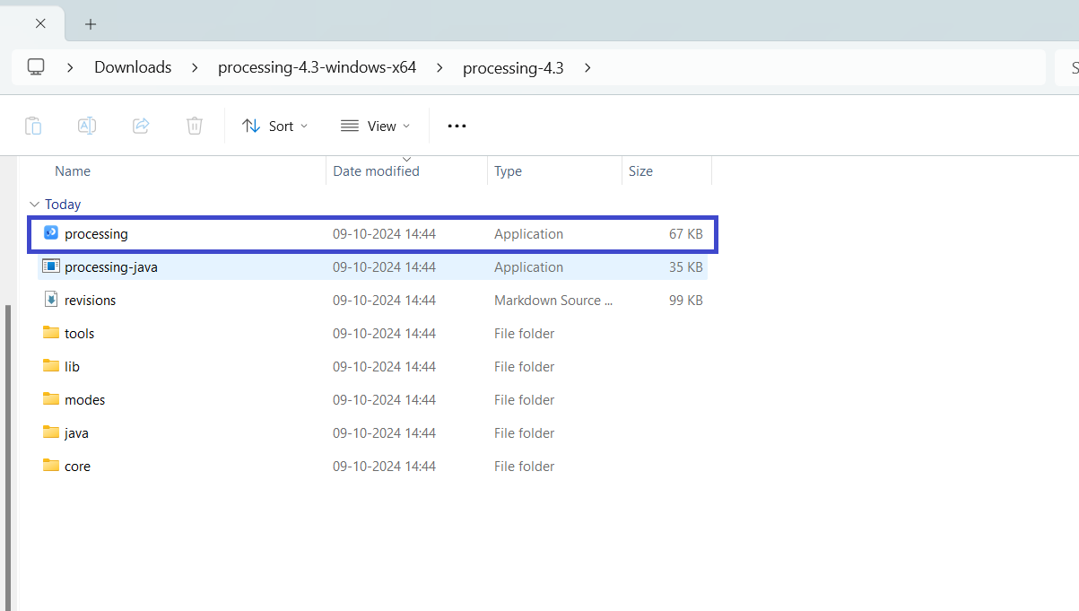
Step 2: The extracted file contains a program that, when clicked, opens an interface as shown below.
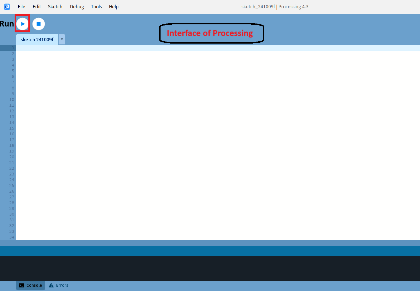
Step 3: The interface of Processing as shown below.
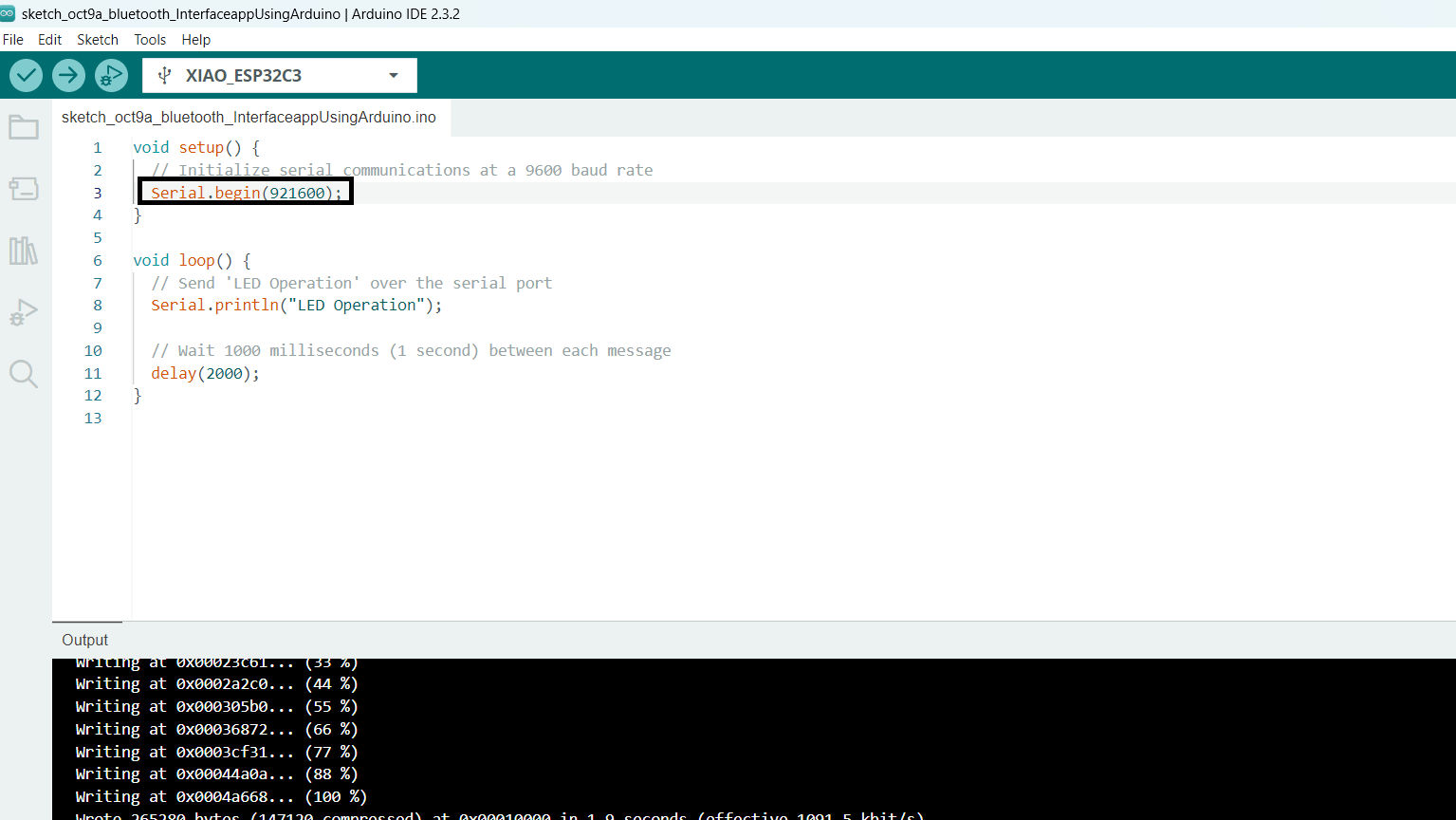
Step 4: I already had the Arduino IDE, so I used it to write a program for "LED OPERATION." Then, I connected the ESP32C3 microcontroller and uploaded the code.
Here I first kept baud rate 921600 but then I changed it to 9600 because some errors.
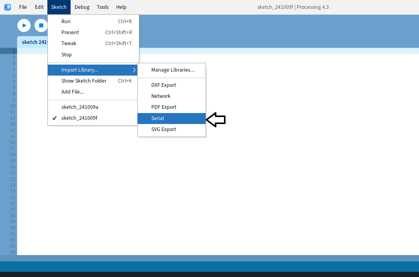
Step 5: Open the Processing software and begin by importing the "Serial" library to enable serial communication.
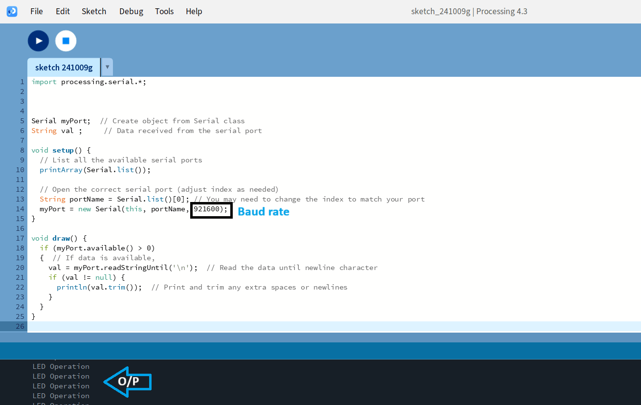
Step 6: Write Code in Processing.
After installing the "Serial" library, use the code below to receive messages from the Arduino IDE and hit the run button.
I received a message from Arduino that is displayed in Processing as "LED Operation." This represents the communication process between the Arduino IDE and Processing through the microcontroller board ESP32C3.
Step 7: Establishing Communication Between Processing and Arduino IDE.
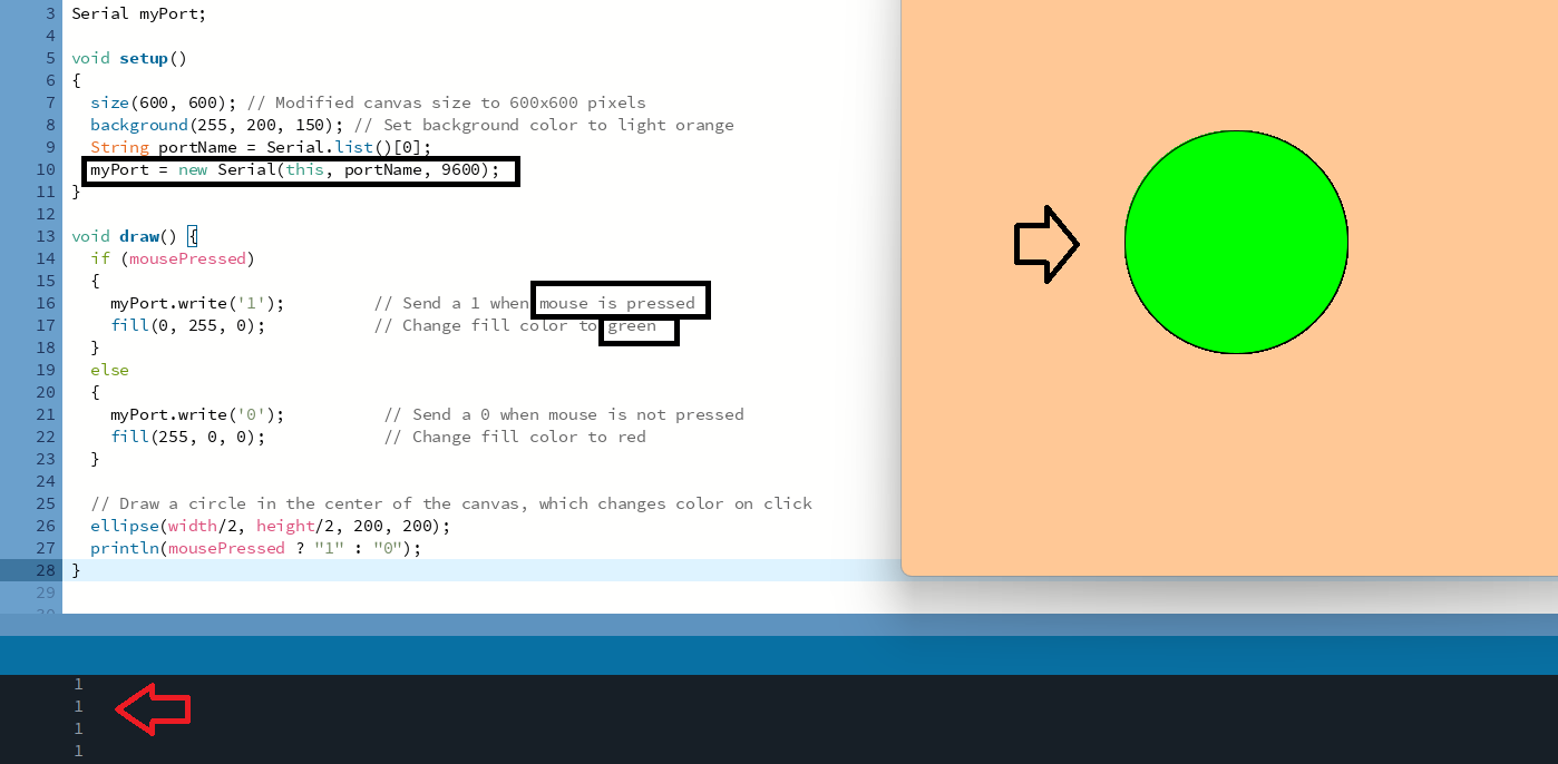
Write a new Processing code to control the board by creating an elliptical canvas that functions as a remote. Then, write the program in Arduino.
Initially, I developed code in the Processing environment to create a canvas interface with an ellipse shape resembling a button. I want to implement a feature that changes the color of the button when it is clicked.I created some code, but I encountered an error, and the ellipse is not appearing on the Processing canvas.
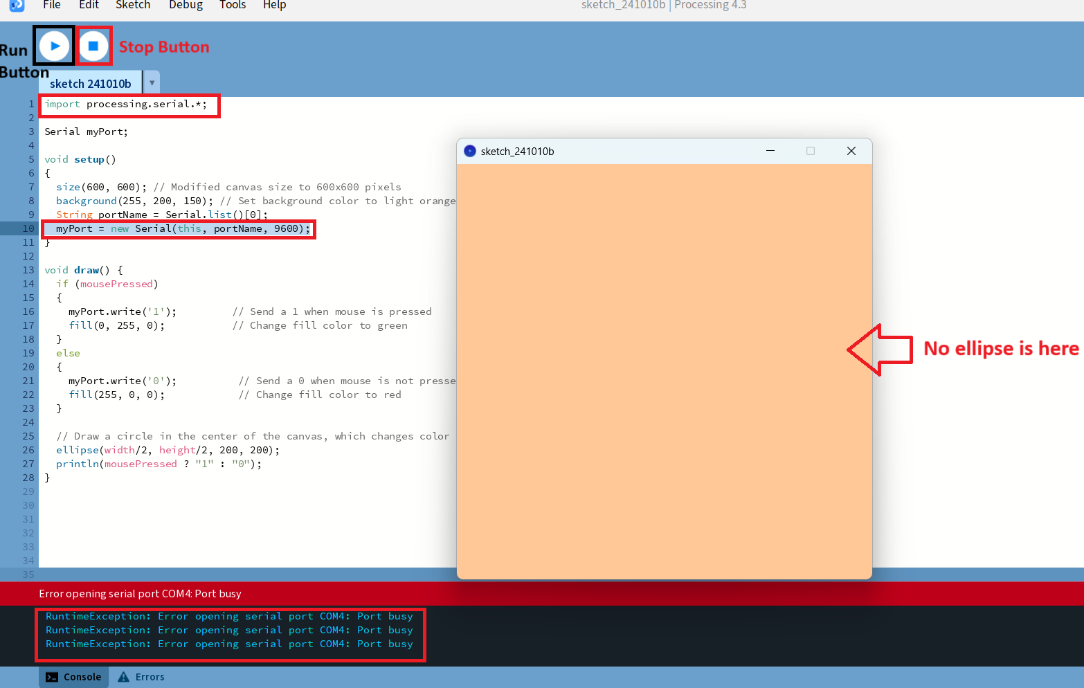
After experimenting with various options, I discovered that the button shown in the image is the stop button. It's necessary to press this button before proceeding to the Arduino IDE so that I am getting the error "Port Busy".
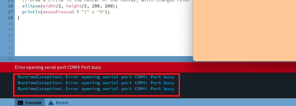
Then I again upload the code in arduino by changing baud rate 9600
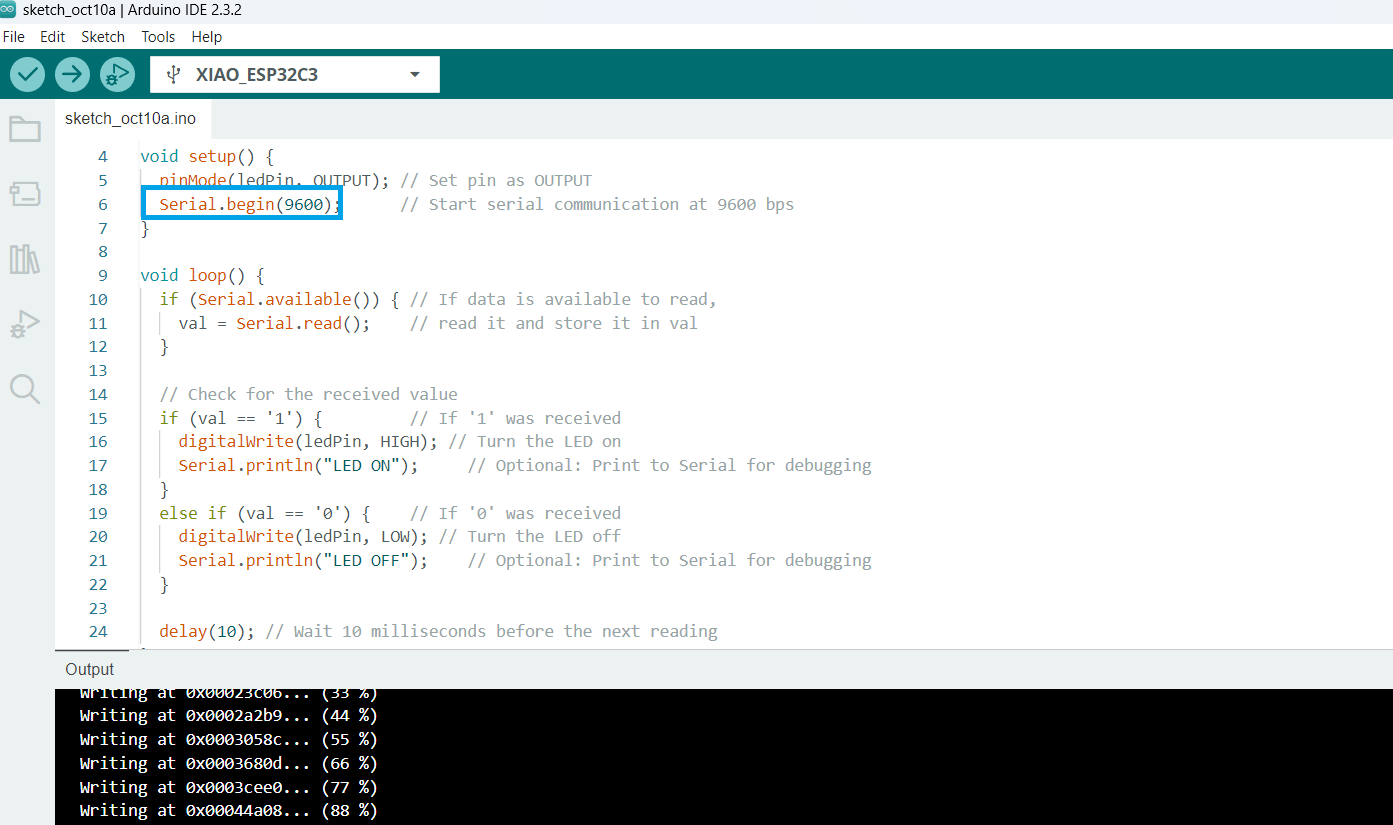
Then Run the code in processing and recieved output as "LED Operation".
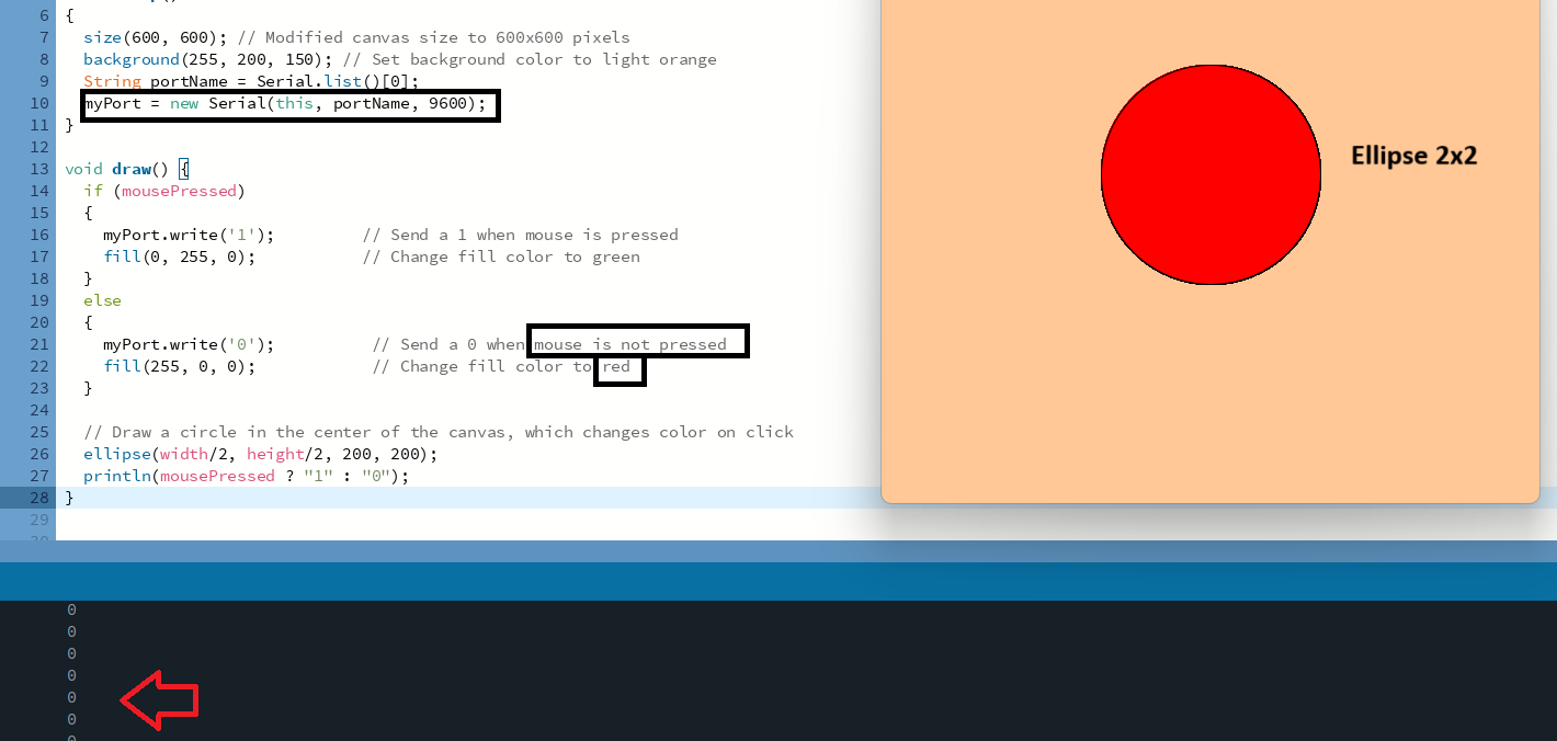
When I click on the ellipse with the mouse, its color changes from red to green. Additionally, the console output changes from 0 when the mouse is not pressed to 1 when the mouse is pressed.

