3. Computer-controlled Cutting
This week I worked on understanding and exploring the laser and vinyl cutters. I also figured out how parametric sketches are made and how one can find the kerf of the laser cutter.
This week’s documentation is divided into three main categories:
- Group Assignment:
Understanding Laser cutter setting
Testing joints
Finding the kerf loss of the laser - Vinyl Cutter Trials
- Parametric Construction Kit
In our lab, we have the 100 Watt Laser cutting machine by SILasers (Suresh Indu Lasers): LINK
I am attaching the Standard Operating Procedure (SOP) for Riidl lab here as a pdf for better understanding of how to use the machines in our lab. These are guidelines made by the lab, Riidl:
Riidl Laser Cutter SOP
Riidl Vinyl Cutter SOP
1. Group Work:
Our group from Riidl Fablab consists of me, Himanshi, and Tejas- and of course, our mentors Jesal sir and Pranav sir.
Setting up the machine
- Turn on all power units of the laser cutter machine, including the machine itself, laser generator, exhaust, air compressor, and PC.
- Place your material flat on the bed. The official bed size is 3x4ft.
- Once the file is loaded, set the Z-axis by placing a piece of acrylic or mdf which is 5mm above the material. This is the focus of the laser.
- Set the XY origin simply by navigating to the point you want to set and hit “Origin”. To better understand the XY position of the Laser, you can use the “Pulse” to check exactly where the laser will start. This fires a small beam of laser for a split second.
- Perform a frame check by clicking on the “Frame” option. Make sure the frame is within the boundary of your material. Finally, start the cut/scan.
Speed and Power
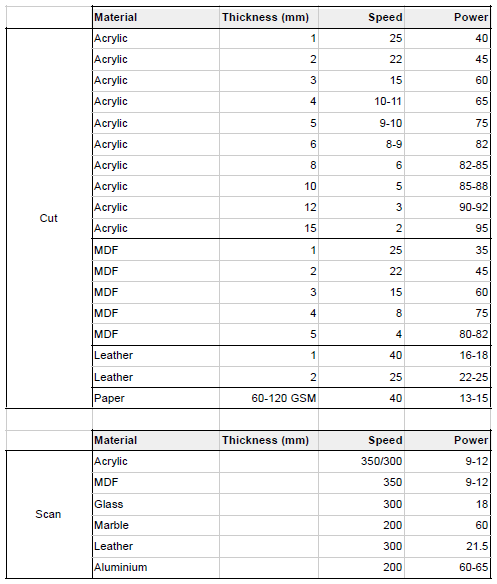
In our lab, we have a printed set of Speeds and Min/Max Powers given based on each material and its thickness. We usually refer to this list to set the Speed and Power.
Joint Tests
We started out by downloading the joints file from the Fab page and cutting them out on the laser cutter. I must add here that being in a design school, we have a bit of prior knowledge of operating the laser cutter. For our college projects, we usually make a vector file on Adobe Illustrator and then export is as a DXF. Then we transfer the DXF to the Lab computer where we open it on RDWorks, which gives the command for cutting.
RDWorks interface:
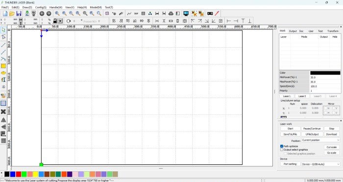
Import files using the Import button on top:

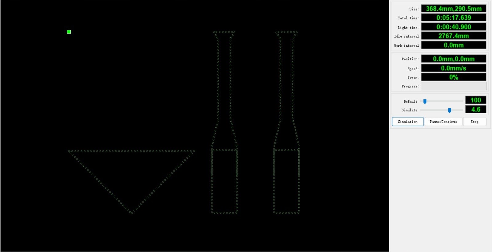
You can preview it by selecting the TV icon

Set the speed and power by editing then umbers here. You can double click on “MODE” to change the mode of the file.

The different modes include:

Dot mode gives you perforations. It is good for making Diecuts:
Pen mode:

Scan mode:

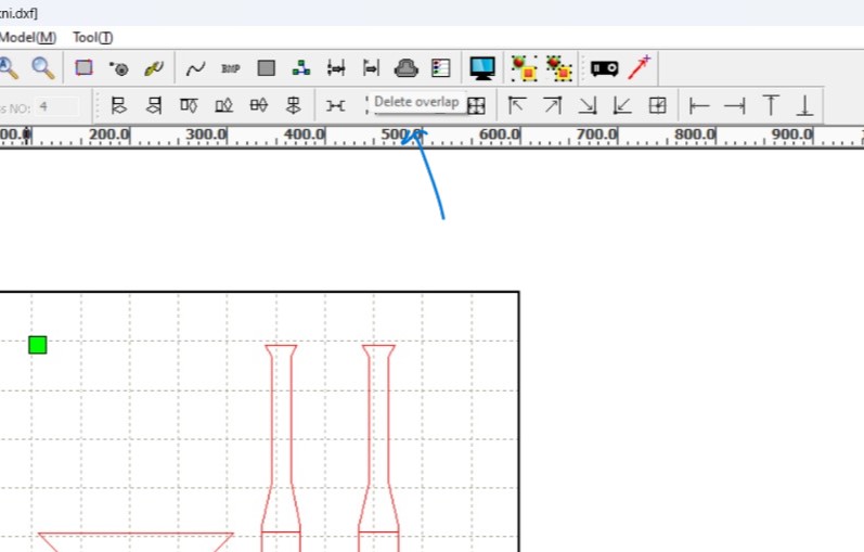
Quick tip: If you want to save space and have an efficient cut, you can overlap lines of your design in your software by snapping them/giving constraints. In RDworks, you can delete these overlaps so that the laser doesn’t keep cutting on overlapping areas.
Here, you can select the color for each vector line and give ‘Speed’ and ‘Power’ values accordingly.
To send to the cutter, you simply click Download as our laser cutter is connected to the PC directly.
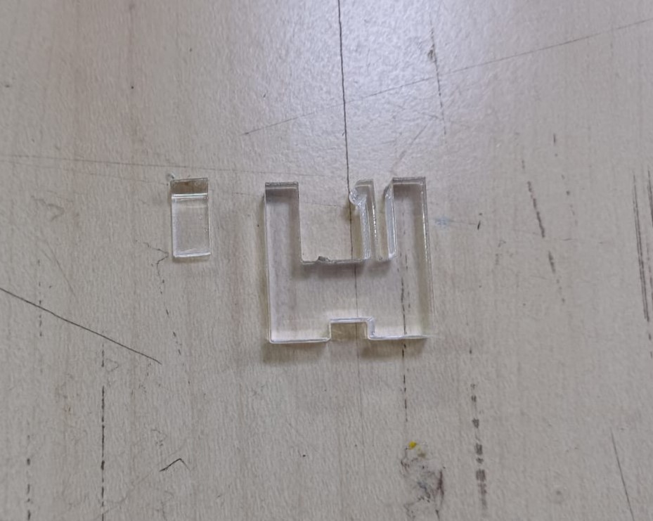
Our first cuts for the fab week 3 were these joints from the Fab page itself. We used a 4.8 mm thick clear acrylic sheet to cut the same. The speed was set to 10 and the Min and Max Power to 75.

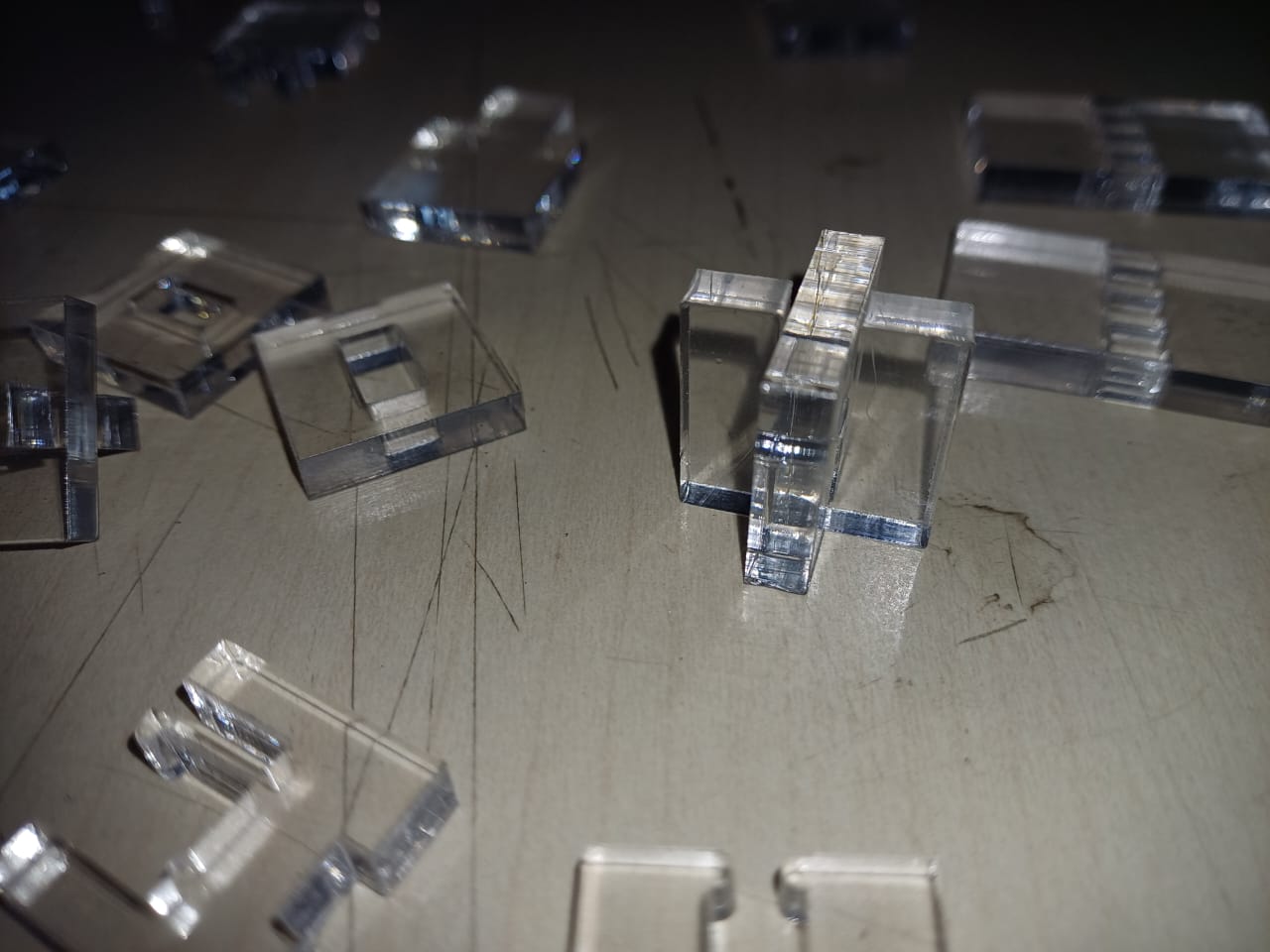
We had not accounted for the kerf here, and so, the joints were loose.
The snap fit joint even broke :/
Modified Comb test for kerf
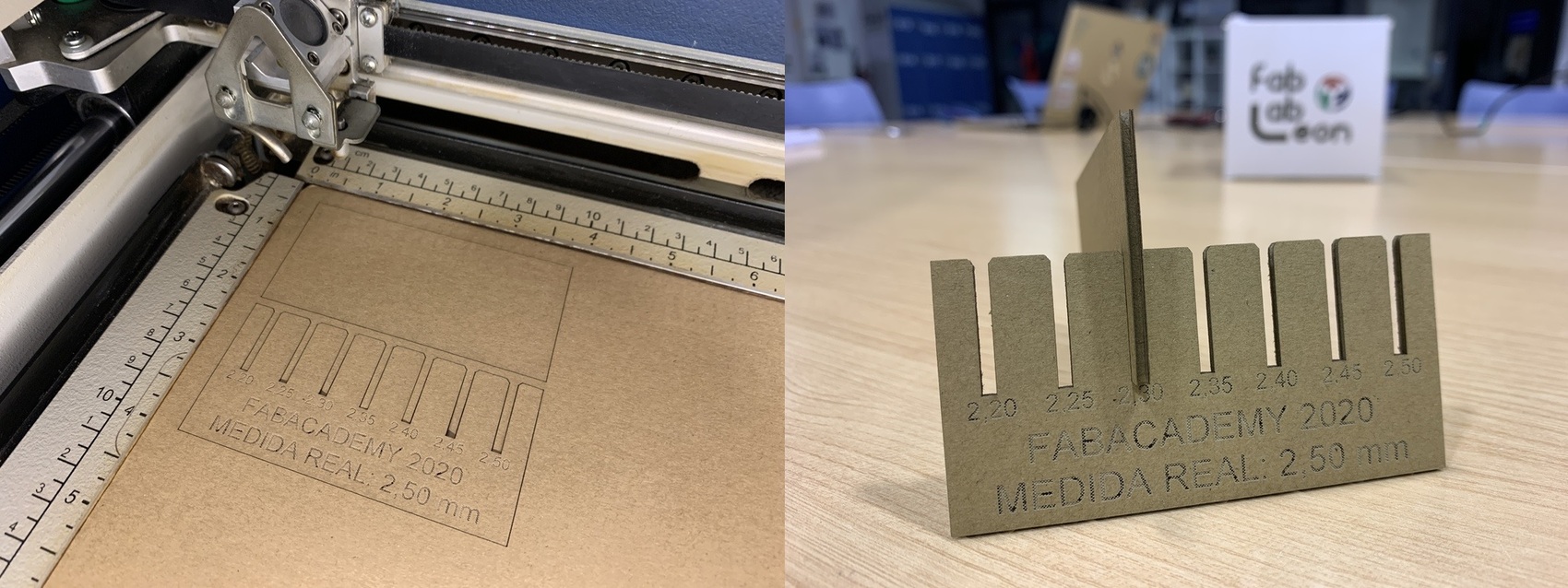
We then went on to cut a comb on the same acrylic to find the kerf.
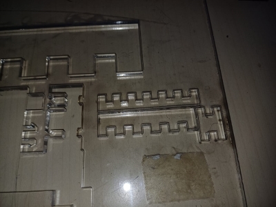
We explored by making our comb variation. This variation consisted of two combs- one had the peg width varying by 0.2 mm from 4 mm to 5 mm, and the other had the slot width varying by 0.2 mm from 5 mm to 6 mm. We used illustrator to make this.


Let us divide the comb into two components- the positive spaces ‘Pegs’ and the negative spaces ‘Slots’. In the above image, the comb on top has Peg widths 5mm, 5.2mm, 5.4mm, 5.6mm, 5.8mm, and 6mm. The comb at the bottom of the image has Slot widths 4mm, 4.2mm, 4.4mm, 4.6mm, 4.8mm, and 5mm. The ‘H-shaped’ bits on the right have a Peg and Slot width of 5mm each.
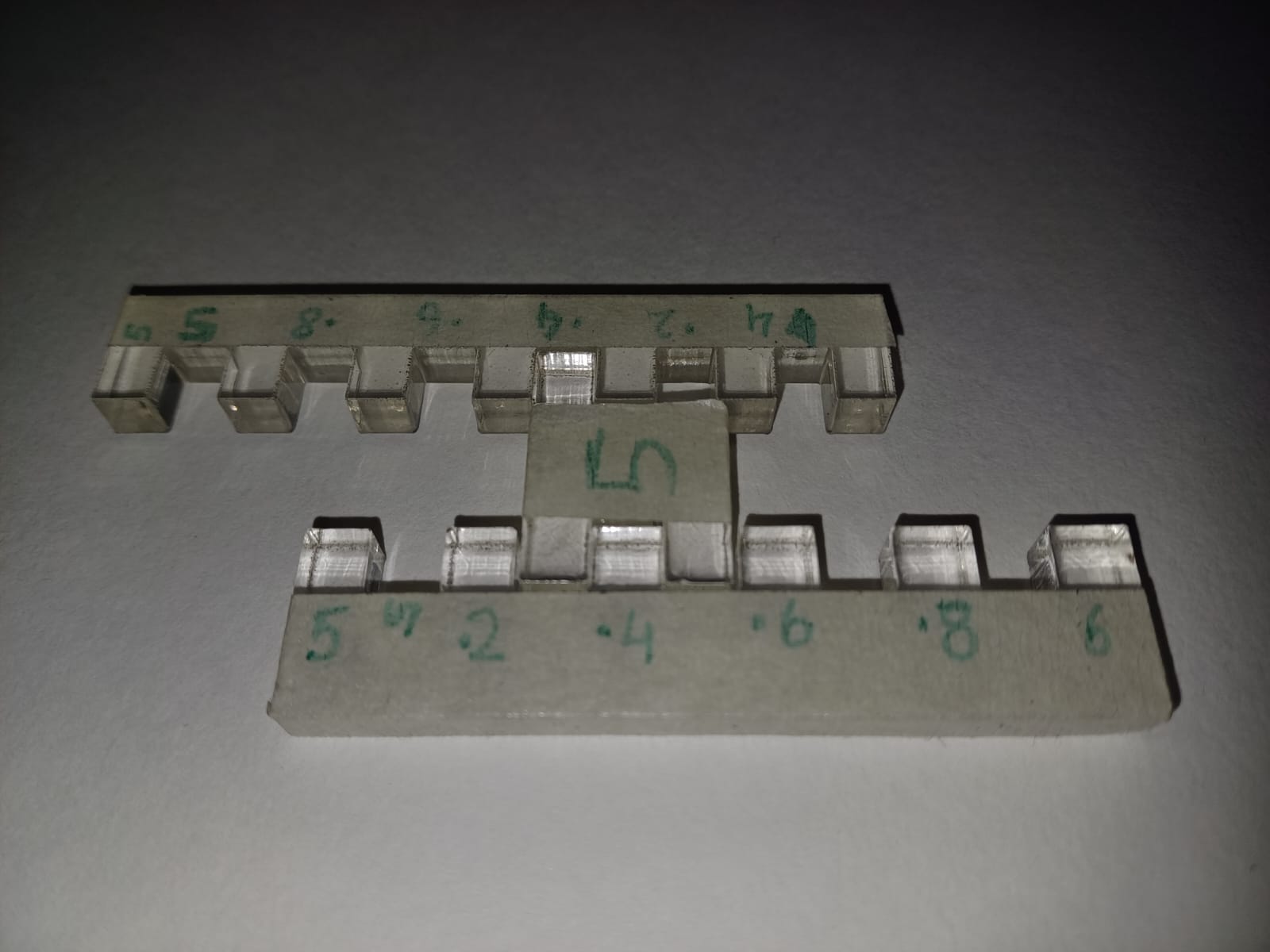

From here, we observed which segment was fitting snuggly and noted it down:
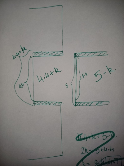
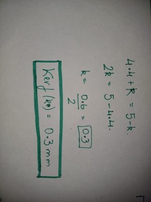
And then we found out the kerf:
Note that we are not trying to measure based on the thickness of the material, we have instead made it such that the fitting happens in the same plane.
Kerf Learnings!
We realized a lot of things here, thanks to our mentors Pranav sir and Jesal sir.
-
Firstly, you don’t connect the comb side-to-side as the thickness needs to be accounted for. Kerf changes based on Material and Thickness.
-
Our mentors had done a simple comb by varying peg and slot widths, so that you could cut this comb on any material and any thickness and then understand the kerf of that particular sheet. We went the long way around and made it a threefold process (as you had to compare the H-shaped piece with either of the lateral combs and check where it fits the best).
-
Good fit =/= Exact fit, meaning you can’t objectively equate the two equations as done above (4.4 + k = 5 - k). This can’t be done because in reality there are many other factors that come into play when two sheets fit tightly. Plus, good fit is subjective- at times I may desire a loose fit and at times I may desire a snug fit.
That being said, the equation is the result of a safe assumption. However, one does not need to do all this to find the kerf loss value..you can simply cut a piece and measure with a vernier caliper to see the difference in the input measurements vs the actual measurements.
2. Vinyl Cutting!
The Vinyl cutter is a tool that we wanted to use for a long time over the last three years as a part of our bachelors design course but were never able to.
Finally, we learnt how to use it and tested it out!
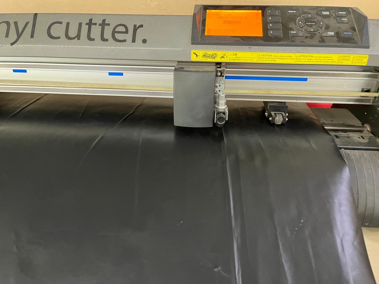
We started with understanding the basics of the vinyl cutter we have, the GRAPHTEC Cutting Plotter CE7000.
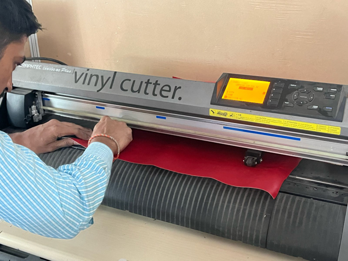
Setting up the machine:
- Start by properly setting the knife of the vinyl cutter. Adjust the knife tool screw as needed for proper setting.
- Manually insert the vinyl sheet into the machine.
- Flatten the material and align the stoppers with the blue part above.
- Ensure the handle is locked after aligning the material to prevent movement during cutting.
- Initiate the cutting process. Initially, the paper roll will pass through without cutting to estimate the total size. Then, it will pull back and commence actual cutting. Please be sure to keep your fingers away from the machine while the machine is functioning.
Software:
We prepared a DXF or SVG vector file. For my assignment, I used the batman SVG available online.
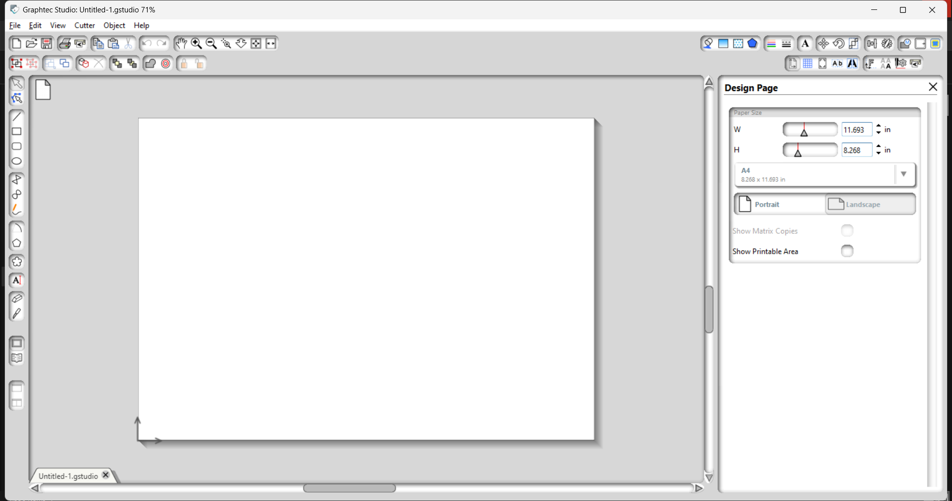
We use the Graphtec Studio software to connect to the vinyl cutter.
This is how the software appears:
We start by opening the DXF file from the File option

Quick note: If you want to use an image, you can load an image on the Graphtec software and use the Image Trace option to vectorize it.
We then let the vinyl cutter do a test cut of its own. This turned out as such:
After that, I went on Google and downloaded a Batman logo PNG and loaded it onto the software Graphtec.
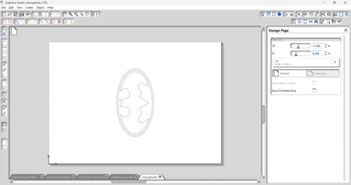
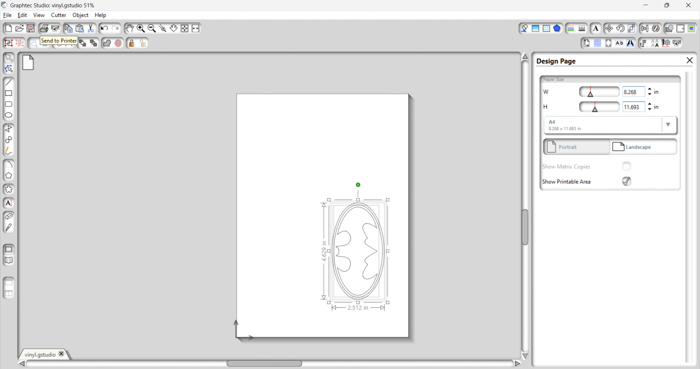
The software shows you the dimensions of the file.

Placing the DXF on the sheet
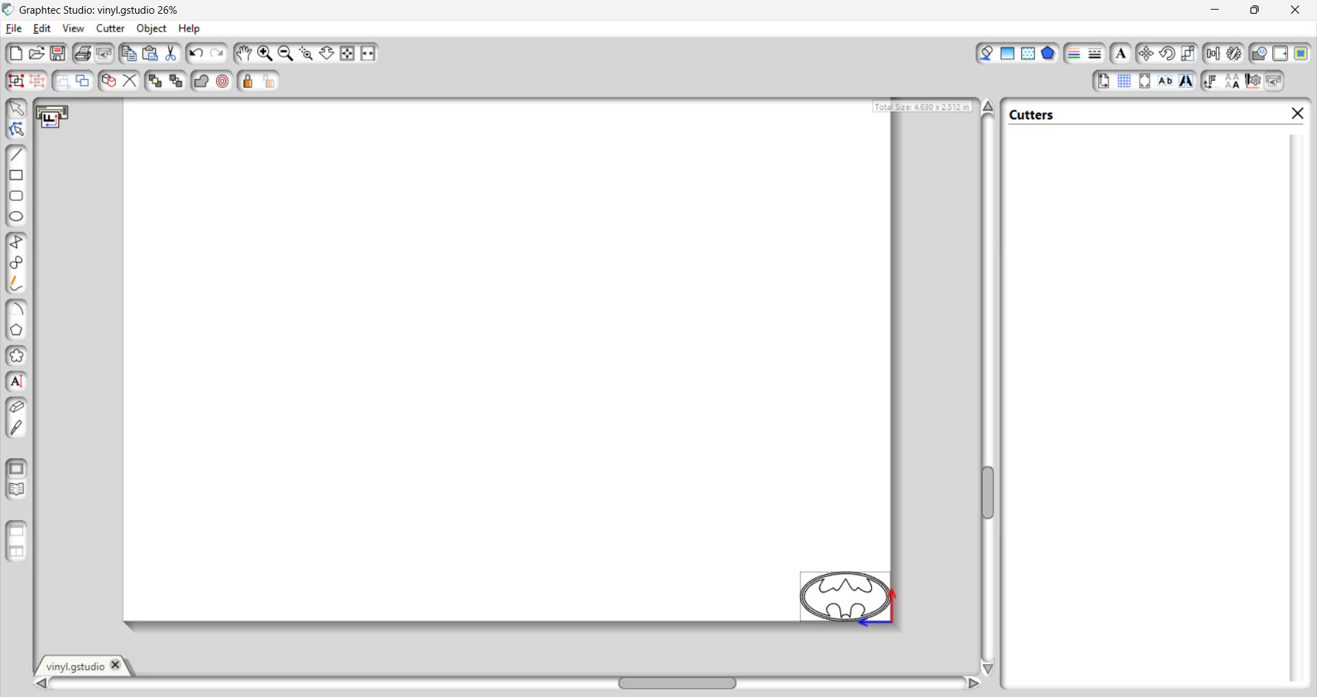
You can also enable a grid to layout the DXF better.
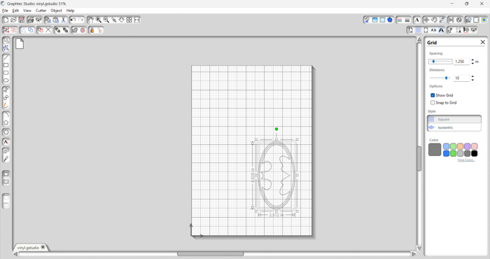
Then, we scaled it enough to match the sheet size we had loaded.
And then we finally hit Cut!…and it disappeared!
Turns out, we were hitting the wrong button. The “Cut” we hit stood for cut-copy-paste cut. We laughed. Quickly, we found the right output- the right “CUT” button and hit it.
You need to use the Send to Printer option to get the vinyl cutter to begin cutting.
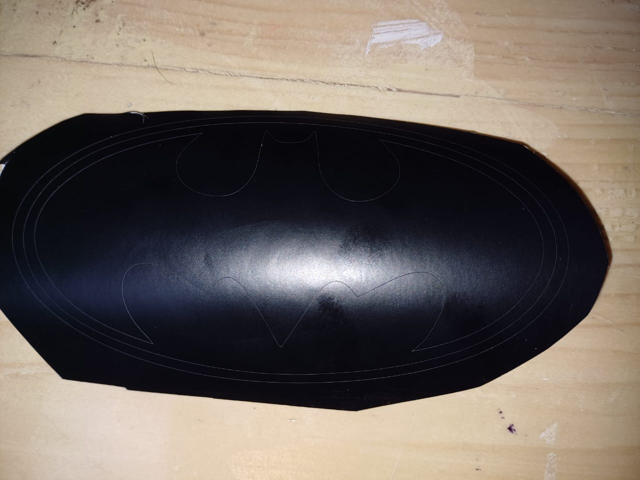
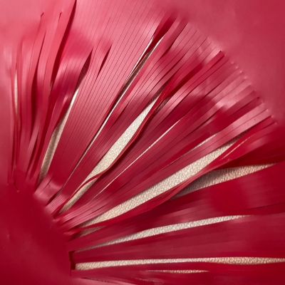
Weeding:

Final:

Some areas of the cut were not done properly. I’m not sure why this happened. The final outcome became a tad uneven due to botchy weeding.

Once the vinyl cutting is done, you can use Transfer paper. Transfer paper is a special kind of paper used to transfer vinyl stickers from their backing paper to the desired surface. It has a sticky side that adheres to the vinyl sticker, making it easy to move the entire design in one piece without distorting it.
After weeding your vinyl design, apply and smooth the transfer paper, then lift and position the design where you want to stick it, and finally transfer it onto the surface.
3. Parametric Construction Kit
I understood parametric wrong.
And here’s what I started with:

A dragon!

I even hand cut it to see how it looks
And then it dawned on me: Parametric = one parameter defines the system, and it should be such that you can edit it easily, and the shape of the unit has to remain constant.
So the dragon went flew out the window.
From there on, I chose a basic shape inspired from the original dragon sketches and used that.
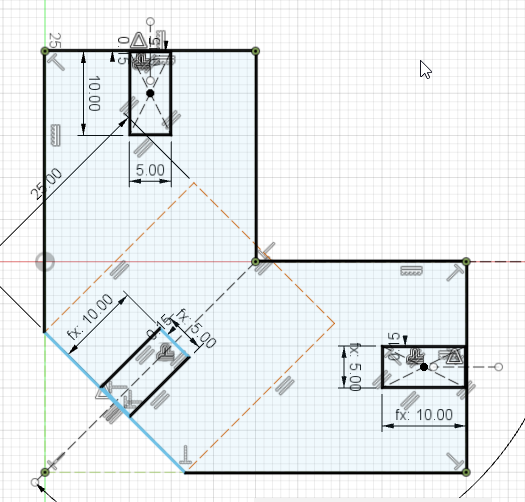
I made the sketch on fusion and linked the slots such that changing one would result in changing all. I went on to export the DXF and get it to illustrator where I could play around with the positioning. I didn’t realize that I could do this on fusion itself so that was a learning for me. Once it was ready, I went on to take it for cutting.
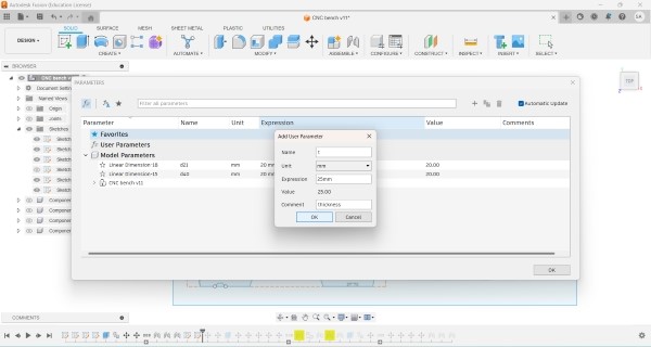
In order to make it parametric, we can use 2 methods on Fusion 360:
The First Method is to the panel on top and select the “Configure” option and then the “Parameter” feature. This way you can enter a designated letter as the parameter and give it a value and unit.
Now, everytime you give a dimension to a line, you can simply enter the designater letter instead of the numerical value.
For example, the parameter you set is Slot Thickness and the letter you give it is ‘t’ and the value is 25mm. Now everytime I give any line a dimension, instead of entering numbers such as “21 mm” or “3 mm”, I can simply write “t” and hit enter. It will not use the value of ‘t’ which we had designated, i.e. 25mm. When you change the value of ‘t’, all lines marked with “t” will change in to the new dimension. ‘t’ essentially becomes a mathematical function.
The Second Method is to select the a line’s dimension and give it a value. Next, we can select another line’s dimensions and then instead of giving it a number, we can just select the first dimension. This is the method I have used.
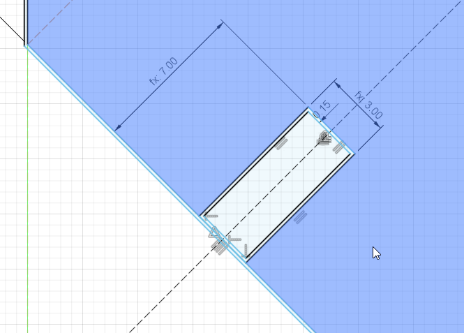
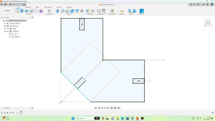
Here you can see that the Parametric measurements are the width and height of the slots marked by the “fx” symbol. This means that they are a function of another dimension.
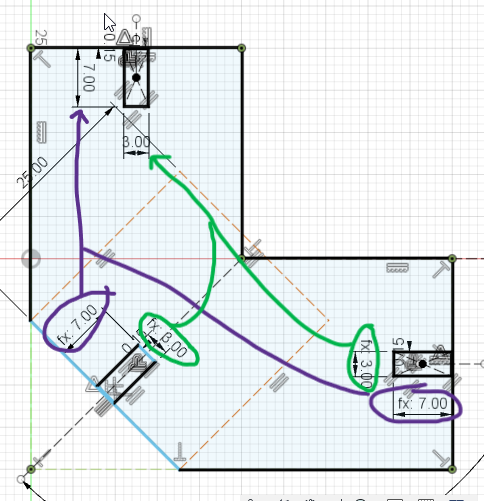
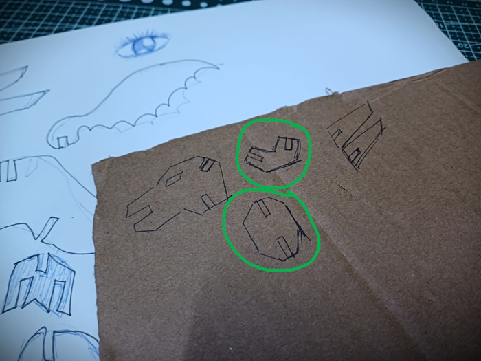
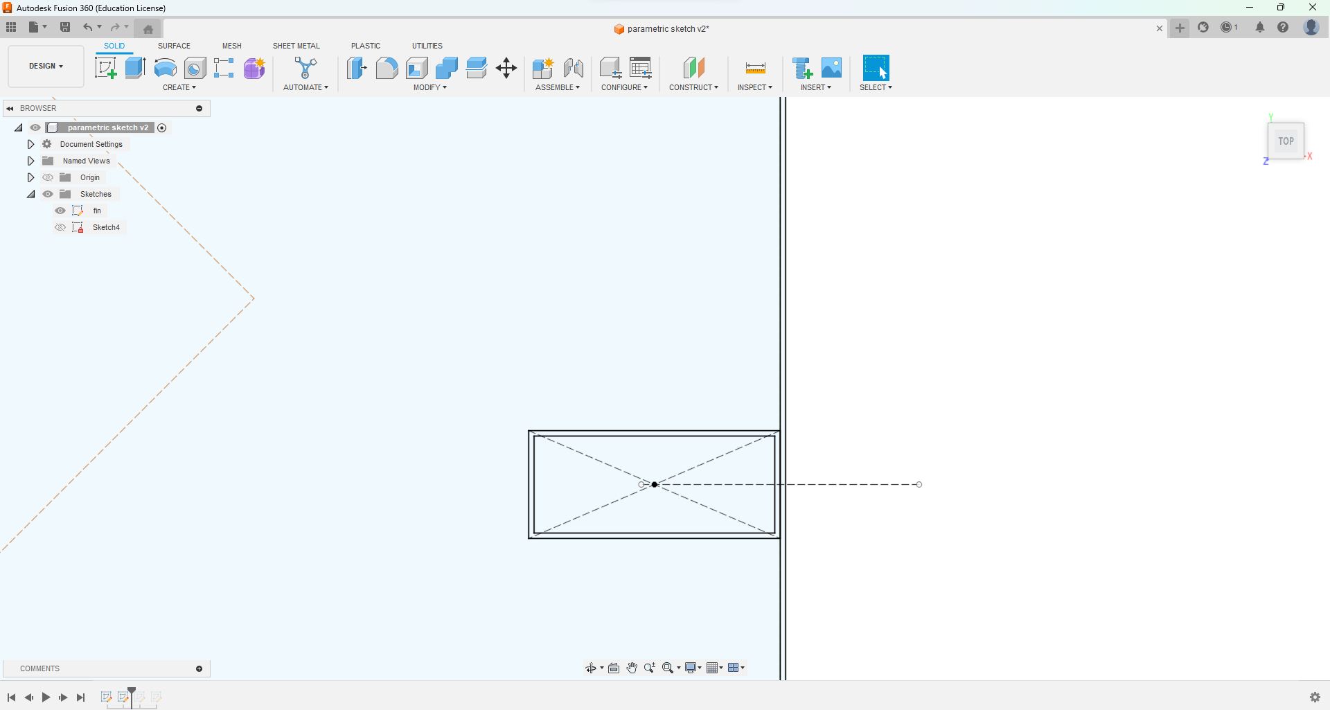
Here, the ones circled are the functions “fx” of the parent dimensions which are shown without the “fx” symbol. First, you double click on any line which needs dimensions and you give it a value, say “3mm”. This becomes your parent dimension. Next, you double click another line which you want to link to the parent. Now, once you double click, the text/number box appears. Here, single click on the parent dimension. Your selected dimension will show a letter and a number such as d1, d2:
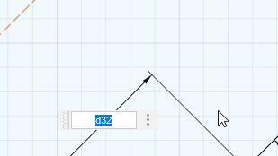
Hit enter. Now your secondary dimension is linked to the parent and when you change the value of the parent, the secondary also changes. Doing this for all the slots will achieve a parametric measurement of the slot.
When you alter the measurements of the parent slot, the rest will automatically change:

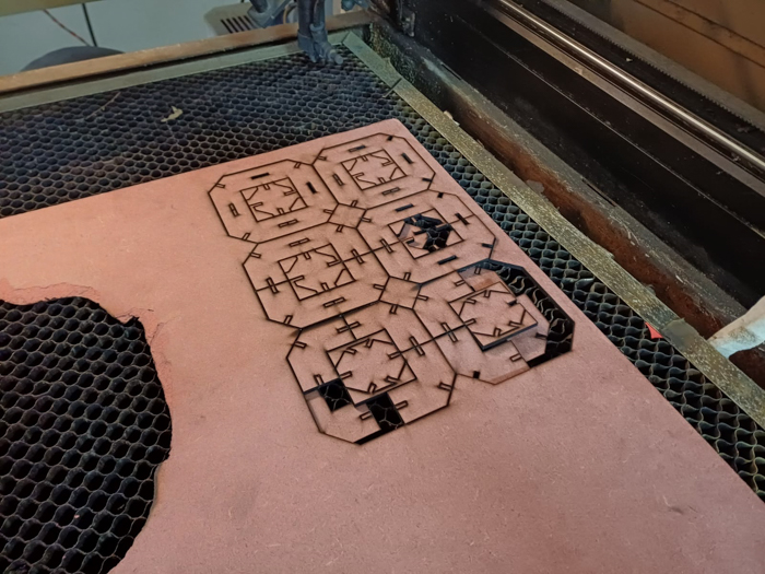
I wanted to use mdf for my kit and went on to find a 3mm mdf lying in our storeroom. I used a speed of 15 and a Power of 60 (min) to 70 (max).
Initially, I gave the digital sketch an offset of 0.15 mm (half of the kerf value we found in the Group Assignment section). I went ahead and cut with this value and it resulted in a failure. The slots wouldn’t fit. I realized then that the kerf would be different for this material. Plus, the bed of the laser cutter was not perfectly horizontal and so the angle made the laser focus better in some areas and worse in some areas thereby varying the kerf.
To tackle this, I made the cuts with the kerf value as mentioned, and since the resulting slot was only a few mm away from the desired measurement, I used a sandpaper and cutting blade to scrap off excess slot mdf.
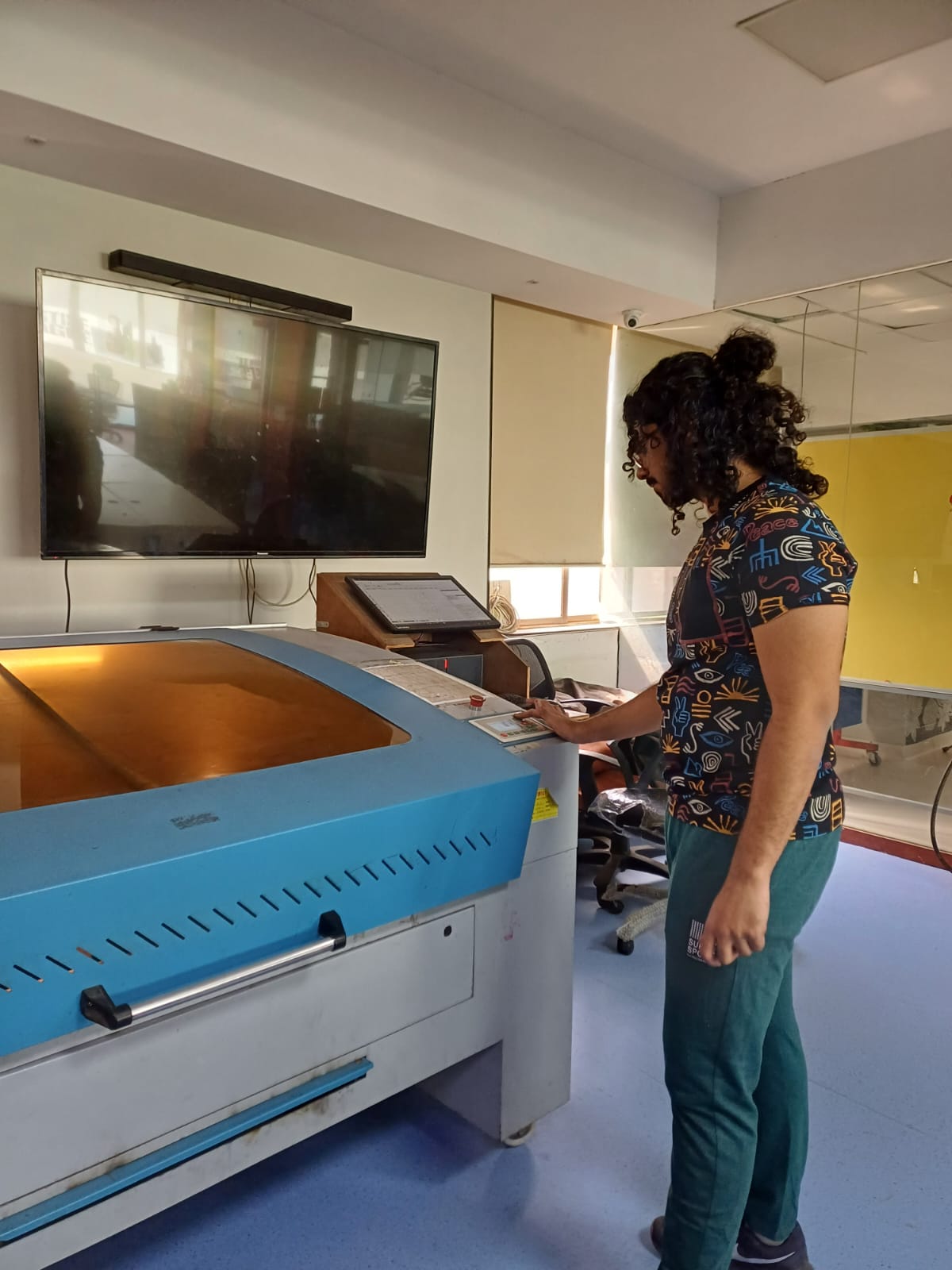
Me at the cutter
The cut sheet
All pieces arranged
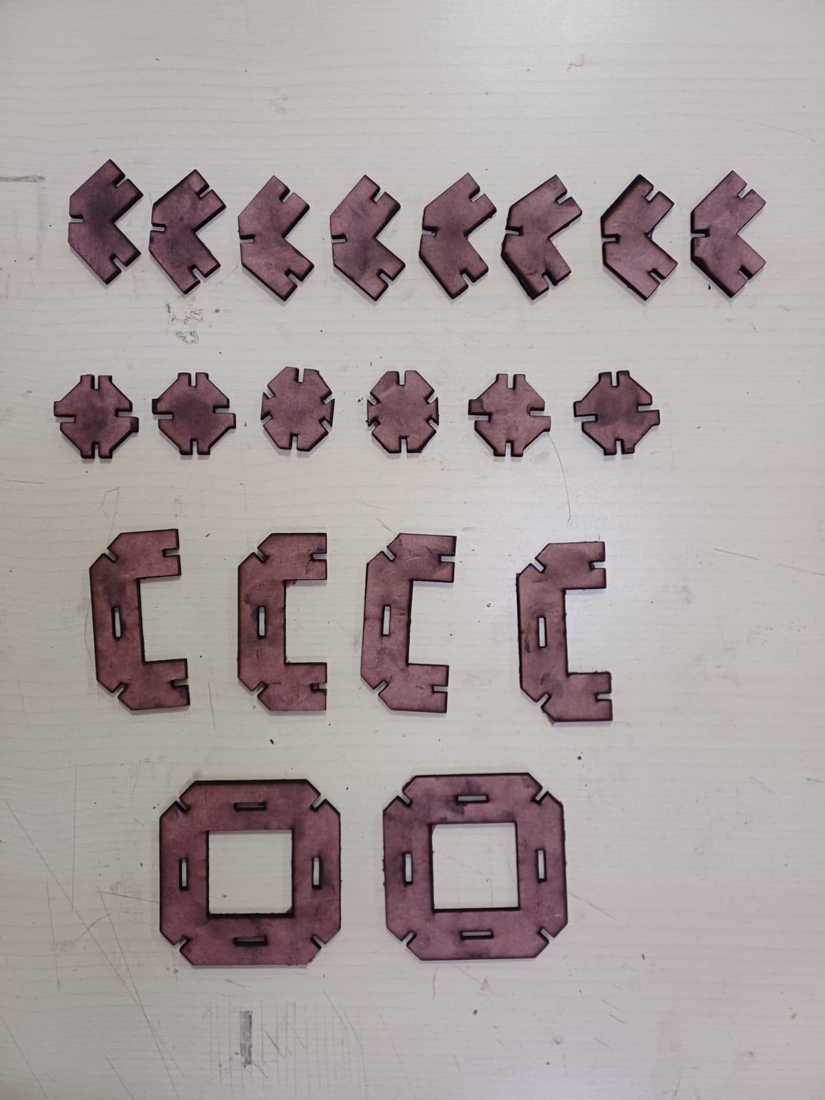
This is how it should fit
And the other octagonal piece would fit as such
However, the first component did not fit

The second one did


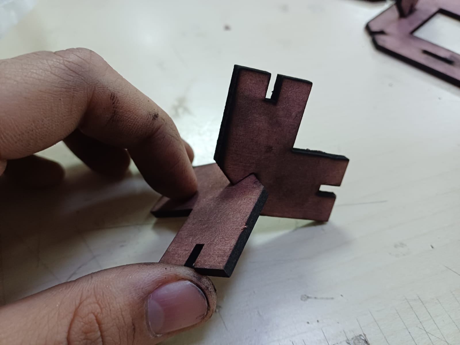
After a few trial and errors I finally got a set which fit somewhat together. Here’s how that looked like:
Hero Shots (Parametric)
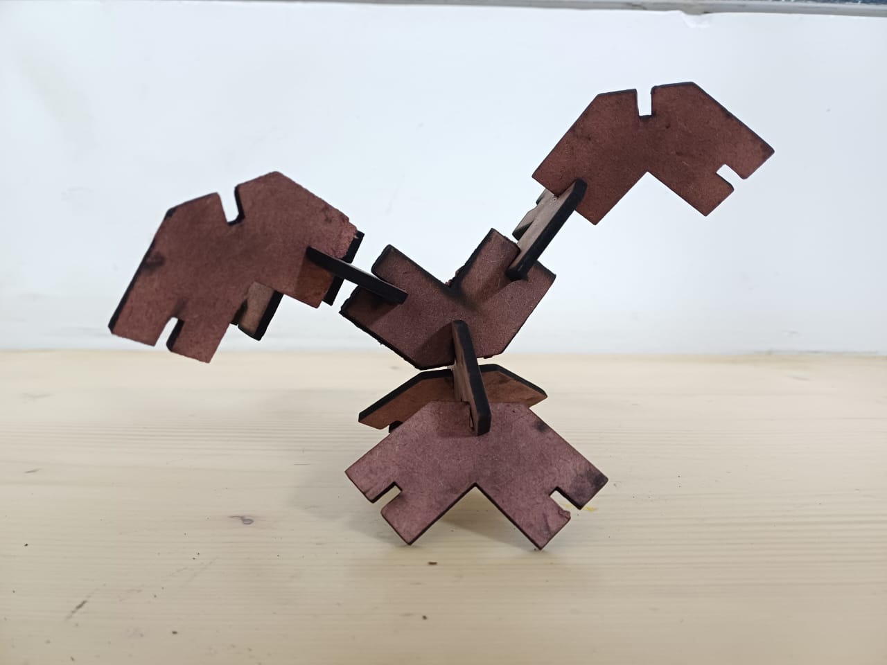
The first fit! Meant to resemble Rayquaza the pokemon (or an elongated creature such as a snake or dragon)!

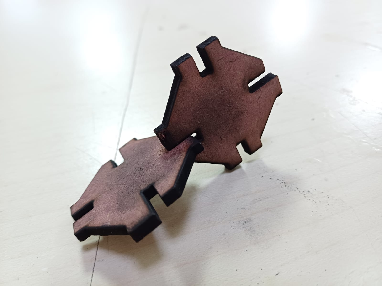
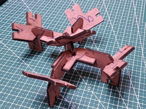
The second fit! Meant to resemble a reindeer!
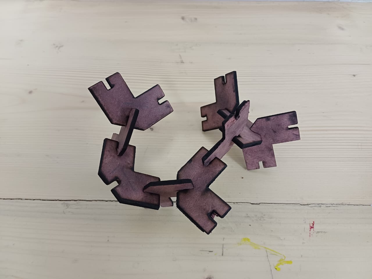
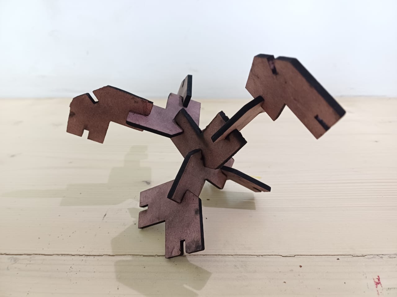
The third fit! Meant to resemble a bird (such as a rooster or an ostrich)

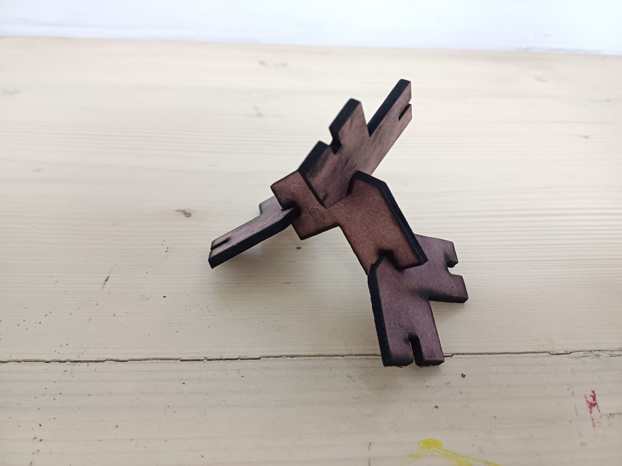
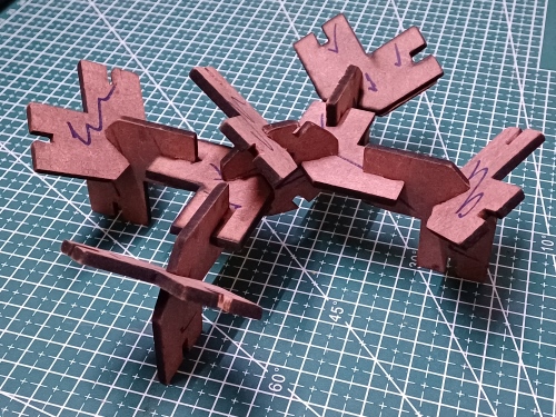
Final one: Looked like a Spider or Drone!

Yet another Parametric trial, to-be-cut
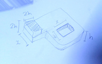
In my initial sketching phase, I tried to think of something in the 3D space and came up with this ‘P’ shaped unit. This unit would be such that it has an additional layer of the sheet stuck with a small portion of the shape such that it justs into the 3D. And this can then be attached in two ways to other units.
The sketch of the unit
Basic shape made using plasticine clay
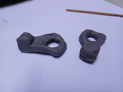
Fitting #1
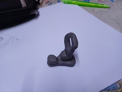
Fitting #2

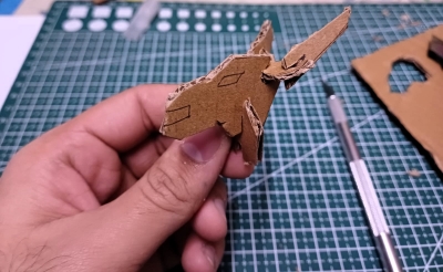
Trial with cardboard to further understand how it will look; Hand-cut
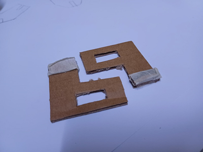
Fitting #1

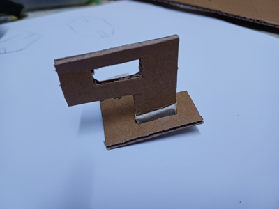
Fitting #2

Bonus : A lovely sunset!
Witnessed this beautiful twilight melting across the sky as a day of Laser Cutting came to an end!


Project Files:
Credits for the Batman Logo I used for Vinyl cutting:
https://logowik.com/batman-vector-logo-2737.html
Dual comb comparison
Batman AI
Batman DXF
DXF for Parametric
Joints Trial
Fusion f3d file
Class Summary and Lecture Notes:
Running notes during week three class:
Class 3 Links:
https://gitlab.fabcloud.org/academany/fabacademy/2024/site/-/blob/main/sizes.md?ref_type=heads - image sizes
Reviews:
Katherine - Chaihua fab - AWOL
Puebla- Jose - UV phone cleaner
Christian- ulima fab- iFurniture
combine it with this: https://www.lightupcane.com/en/ Lifesaver for blind ppl
Alana Duffy - Charlotte- AWOL
Caroline, Barcelona
Ernesto, Ulima- water leak detector
Daniela, Puebla- automotive wheelchair attachment
Basil, Kochi - Tri-wheeled CNC art plotter
Gabriela, Puebla- Enneagram lamps
Midhun Joseph, Kochi - cornering adaptive fog lights for motorcycle
Haystack- mountain school of crafts
Zerocraft- Uni of Arizona
Playing 3D printer as a musical instrument
Idler wheel- smaller wheel driving a larger wheel
Omniwheel wheelchair - Smoov (check on amazon)
Wheelchair battery..not all batteries are safe for flights
no limit on the number of batteries as long as no single battery exceeds 100Wh for flights
Batteries need to be in your carry on. They can’t go in the hold. So if the battery starts smoking. The flight assistant will grab it and put in a fire proof bag and possibly eject it from the plane.
Laser distance measurer- VL53L1X
Shaper Trace tool - startup. HandDraw> Device turns it into CAD
Rhino has grasshopper..not good for parametric or constraint solving. Use solidwks, fusion for constraints
Sketchfab plugin to put 3d content
Toolwheels
BNO085- accelerometer + gyro + micro computer.
I did my final render and animation in OpenSCAD:
edwin dertien-student project
sedat yalcin-student project
akash mhais-student project
Ondsel
Here I try some Python script to generate some basics forms in Inkscape– angela mejia project FreeCAD has OpenSCAD workbench. OpenSCAD is open source materials Bianca went pretty far with the details of the final project
Bernardo wants to present some renderings he did if there’s time
Shape optimization using FusionLaser cutter:
Zund
Othercutter
Ultrasonic Knives
Xtech
Diode lasers vs CO2 lasers
Fablight- startup by student..fiber laser. Greater wattage. Cut metal parts
LightCon
fabulaser by Danielle Ingrasia.
Plasma cutter- melt thru metal..used to be v messy. Similar to welding
Waterjet cutting
I got some steel cut to weld during wildcard week if anyone wants to see one in action
Wazer- waterjet desk tool
Hotwire- used for architectural models, on foam
Sodick.com - wire EDM
CAD tools need extensions for cutting files (check list)
agrilabs projects
hackaday
Self flapping origami crane using vinyl cutter
Origamisimulator.org
https://fabacademy.org/2021/labs/kochi/students/abel-tomy/week3-Computer-Controlled%20Cutting.html
speaker with vinyl cutter
Victoria- vinyl cutting
Screen printing can be done using vinyl cutter
Weeding- removing the extra parts.
pull in plane, not out of plane. Sheer
Vinyl cutter- most effective, least appreciated tool. You can do almost everything
Vinyl cutter assignment- do anything like laptop sticker
Roland Truevis- print and cut device
CHECK BOTTROP LINA FOR CASTLE CONSTRUCTION USING LASER CUTTER
HALFTONE- for meshes screen printing
Inkscape can produce halftone from any image…
vid1
vid2
Snap fit- few thousands of an inch
Giving Chamfer helps tackle compression and gives guide to the other insert
kerf test with chamfers
adrian
You offset for Kerfs (material left behind)
Compliant mechanisms
This clip talks in depth about flexures inside accelerometers
Demo of the laser beam waist + calibration jig
1
2Air assist helps in throwing away combustion pollutants
For this reason you can create stickers for your laser cutter floor.
Don´t leave unattended 😅
adrian
Master cardboard cutter…
student projectMaterial for laser cut:
Delrin (Polyoxymethylene)- Polyoxymethylene, also known as acetal, polyacetal, and polyformaldehyde, is an engineering thermoplastic used in precision parts requiring high stiffness, low friction, and excellent dimensional stability. Good polymer for machining.
Pasta
NEVER do PVC at it realizes toxins
Shiny metal- NEVER do as it reflects laser back in to the tube
Offset half of the laser path
Do you have any notes on casted vs extruded acrylics? Difference comes in joint tolerance. For images always use cast. Smells awful when cut…and the smell lingers for days in the lab