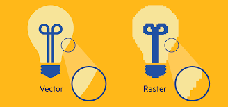
A raster is a technique that defines a two-dimensional picture as a grid of square pixels or
a rectangular matrix that we are able to view through computer display, paper, and many other mediums.
Raster images are constructed through pixels.
Raster prefers graphic formats like GIF, JPEG,PNG and PCX, etc.
Raster are not that scalable.
They work best when it comes to editing photos.
We can use rasters in GIMP, Photoshop, and paint shops.
We can easily convert a raster file into any file format.
a vector is the collection of techniques for constructing visual images straight from
geometric shapes illustrated on a Cartesian plane, such as lines, curves, points, and polygons.
Vector images are constructed through lines, curves, and fills.
Vector uses graphic formats like EPS, WMF, TrueType, PICT etc.
Vectors are scalable to any size.
They work best when it comes to drawings, illustrations, and logos.
We can use vectors in CorelDraw, Illustrator and Inkscape.
We can easily convert a vector image into a raster image.
We cannot change the vector files.
I used GIMP software as a photo editing tool. GIMP stands for GNU Image Manipulation Program, and it is freely distributed. It is a good tool for beginners because it is open source, allowing us to modify it as needed.
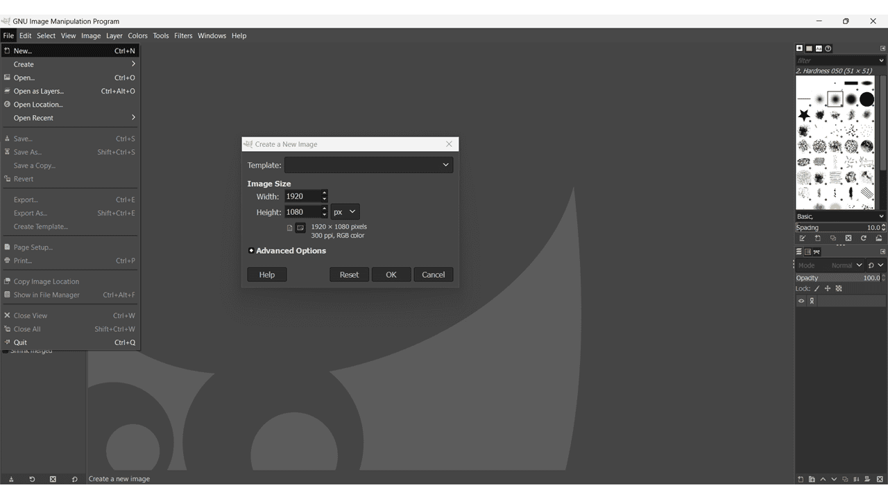
This is the interface of the GIMP software. Click on File > New or we can use "CTRL + N". Then, the "Create a new image" window opens, allowing us to choose from various standard sizes of templates. Additionally, we can define the height and width of the image.
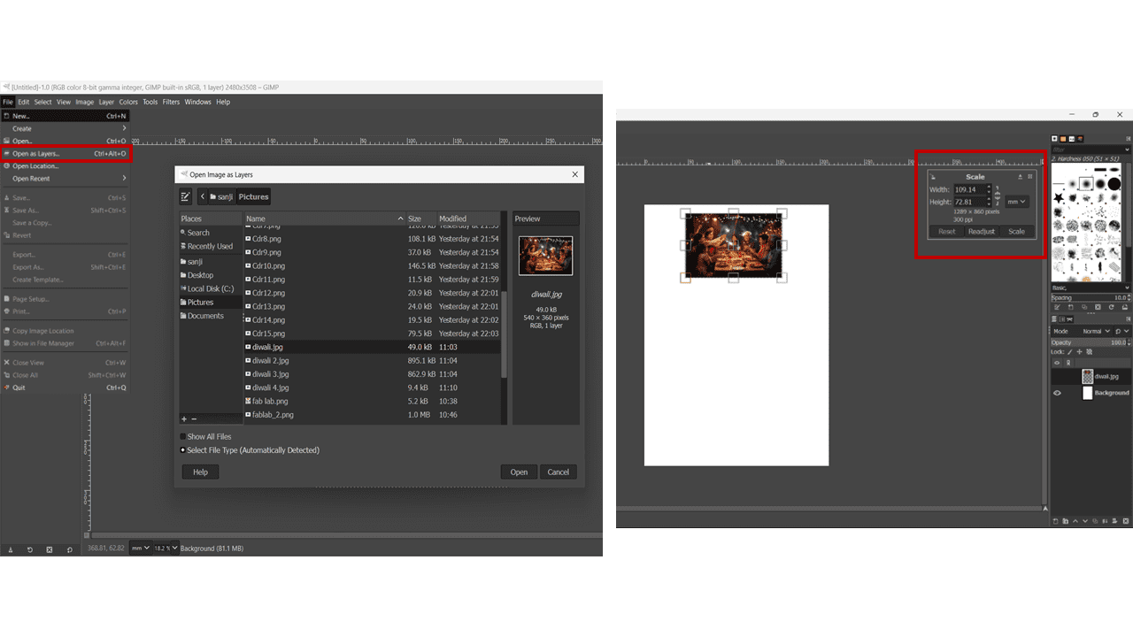
Click on File > Open as Layer, or we can use "CTRL + ALT + O". Then, select the image that we want to edit. We can add different images as different layers.
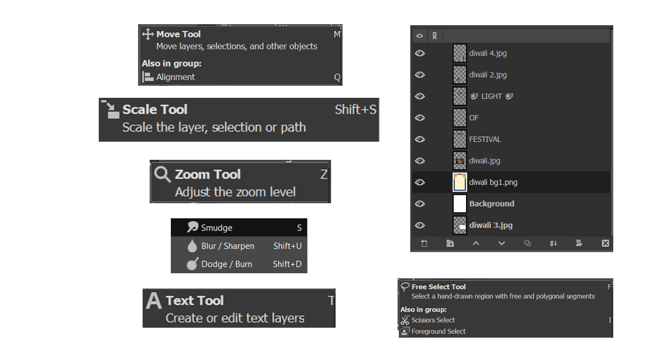
I have used the different commands
Move Tool: It is used to move layers or images on the template. We can activate this command by using the letter M.
Scale Tool: It is used to scale the image or increase/decrease its size. We can use it by pressing "Shift + S".
Zoom Tool: It is used to zoom in/out on the interface or the image on the template. It is activated by the letter Z.
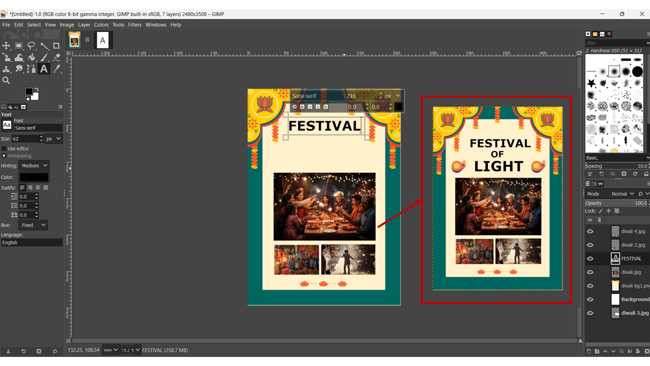
Text Tool: It is used to write text, and we can use different sizes and colors for the text.
Free Select Tool: It is used to select anything on the template.
My main aim in using CorelDraw software is to engrave the image of Shankarrao Genuji Kolhe , who founded the cooperative sugar factory Sahakar Maharshi Shankarrao Kolhe Sahakari Sakhar Karkhana Ltd. (previously known as The Sanjivani (Takli) Sahakari Sakhar Karkhana Ltd.) near Sahajanand Nagar, Shingnapur in Kopargaon. Shankarrao Genuji Kolhe Saheb is the Chairman of the Sanjivani Group of Institutes and established the Sanjivani Group of Institutes in the year 1982, where I am currently studying.
I have used CorelDRAW Graphics Suite X7 for image processing. Using this software, I have transformed a regular image into one suitable for laser engraving.
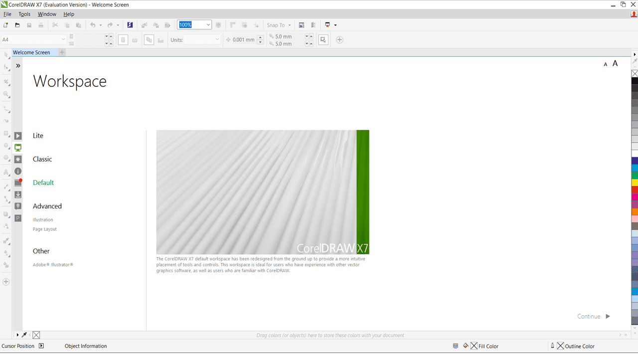
This is the interface of CorelDRAW software or the workspace of the software. Click on File > New Button to create a template for image editing. We have various default size options available, or we can choose our custom size in the template.
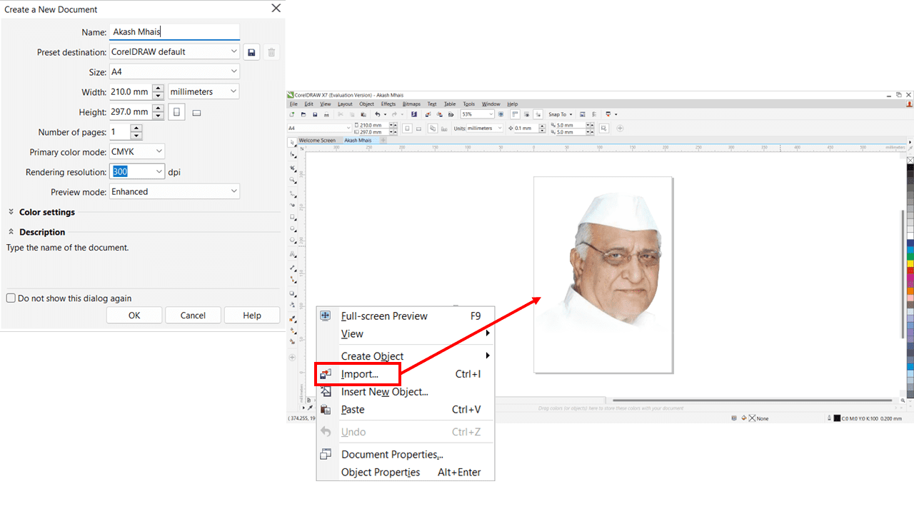
Then, import the original image on which we have to work. We can either right-click on the template or use 'CTRL + I' to import the image.
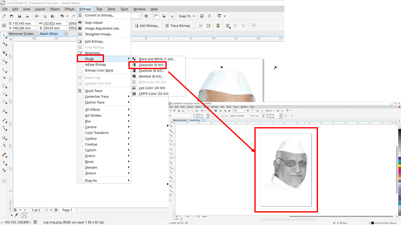
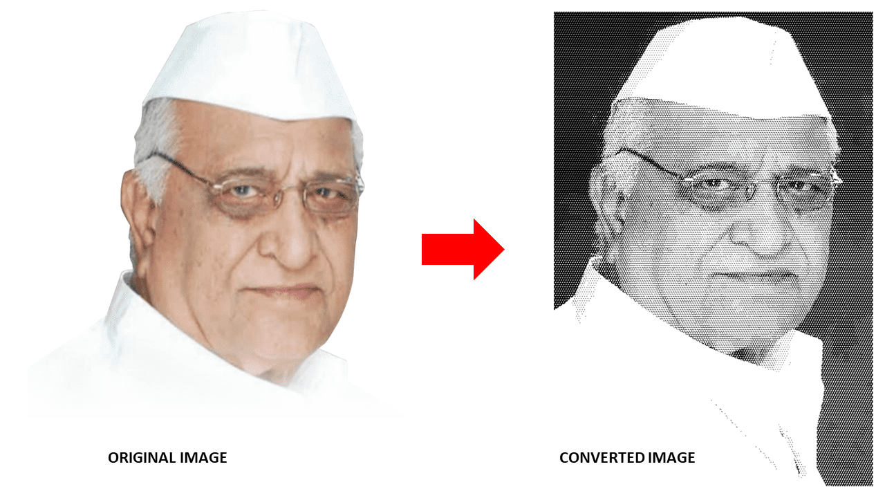
After that, we have to convert the color image to a grayscale image. To do that, go to the Bitmaps tab > Mode > Grayscale (8-bit). This will convert the normal image into a black and white image.
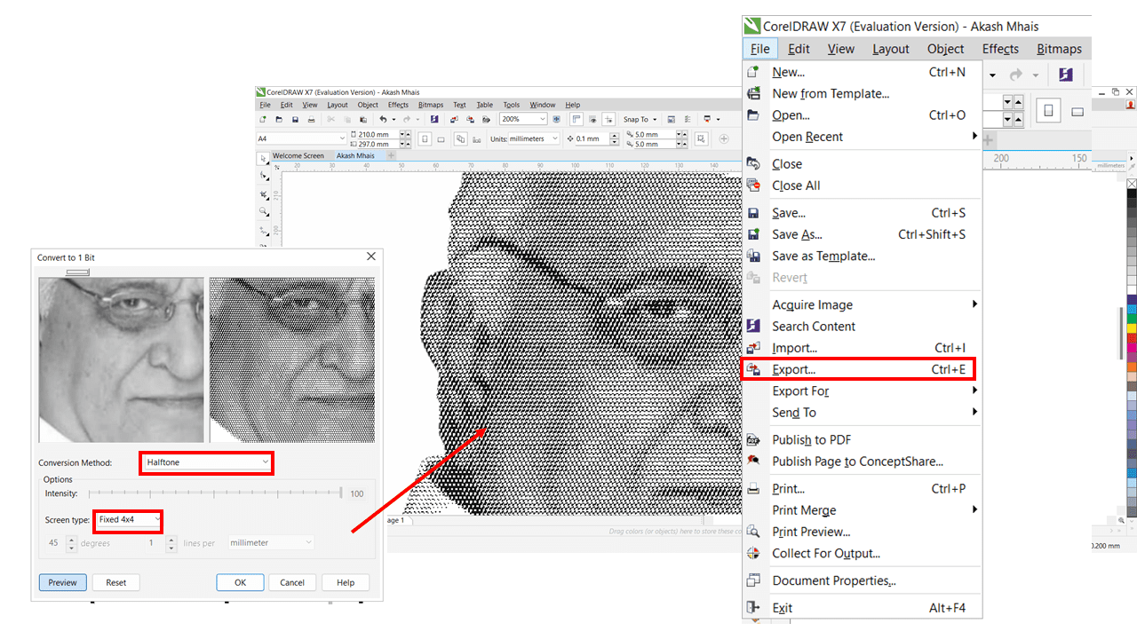
Again click on Bitmaps then click on mode in that Black and White(1 bit)
Conversion Method: Halftone
Screen Type: Fixed 4x4
Export image as: BMP
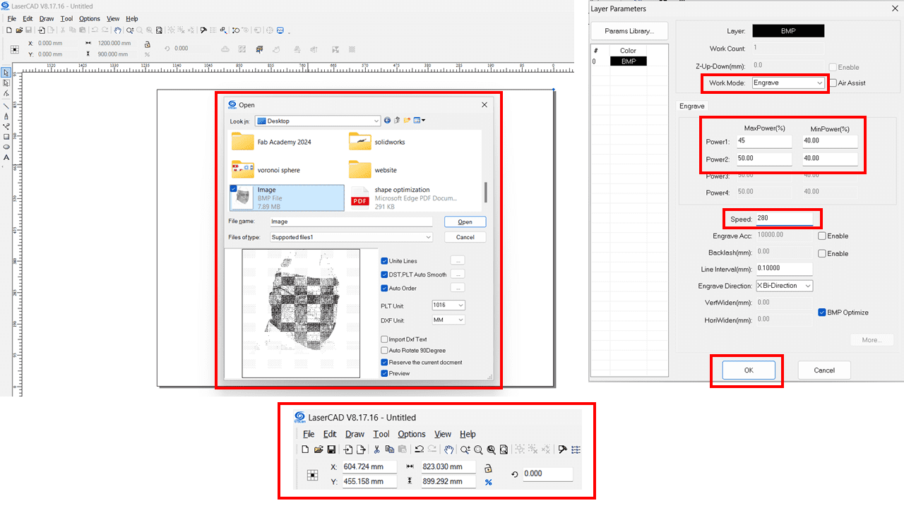
I have used LaserCad V8.17 software for the laser engraving of that image. Here, for importing the image, we can use 'CTRL+I,' or from the File tab, we can import the image. From the top-left corner of the software UI, we can change the size of the image depending on the application. Additionally, we can change the position of the object by adjusting the X and Y coordinates. On the left side of the software, we can set the speed and power of the laser cutter machine. after that we can save the file(File format ->.UD5) or directly download the file in laser cutter machine
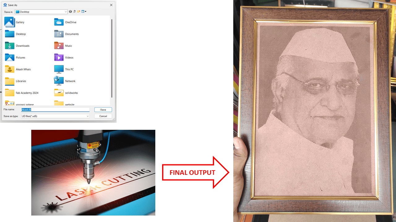
This is the output we get by using the software CorelDRAW Graphics Suite X7 and LaserCad V8.17 & about laser cutting we will going to see in upcoming week
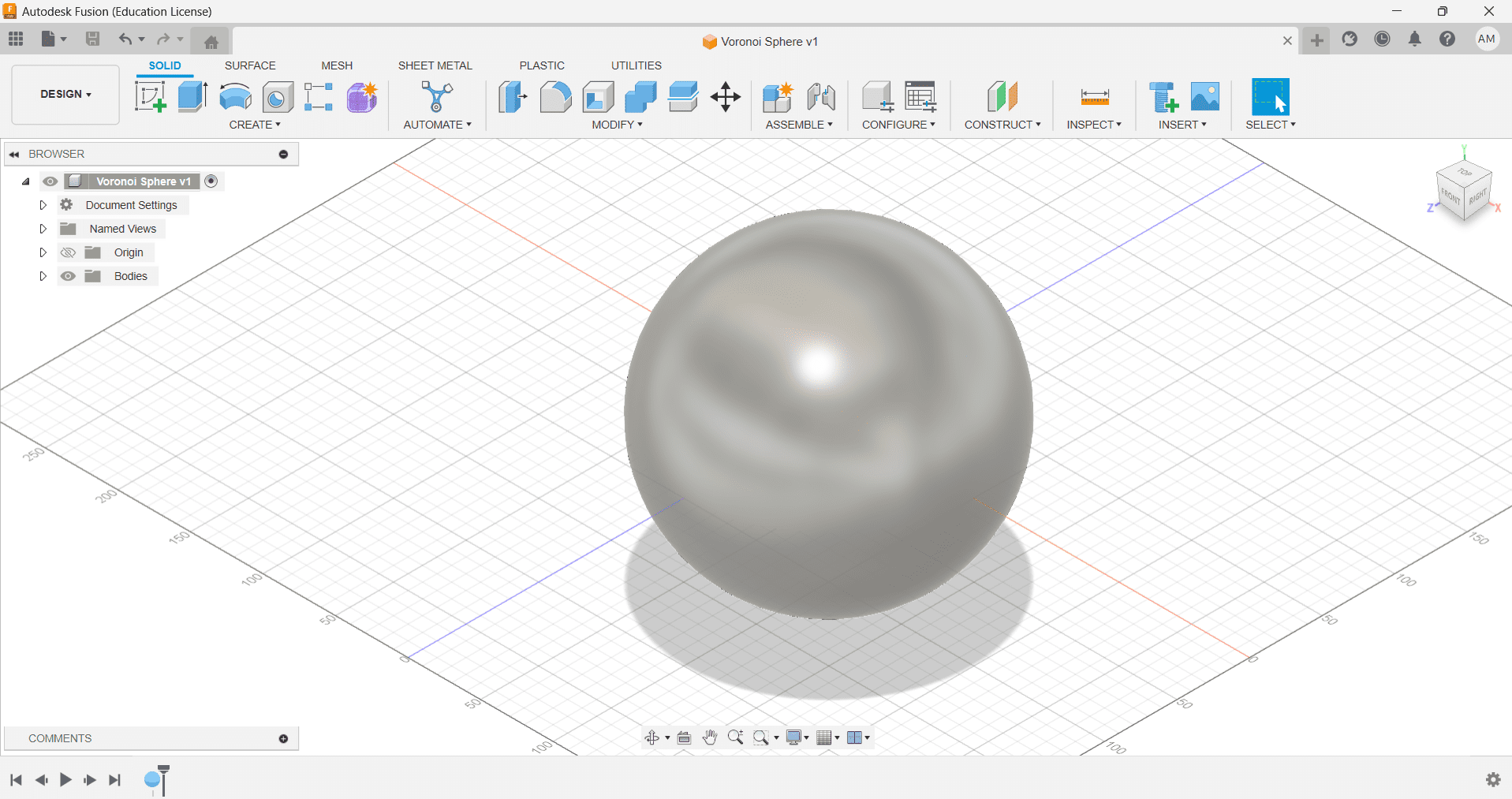
I have decided to explore Fusion 360 by making a model of Voronoi Sphere which is a set of seed points divides space into a number of regions.here i have explored about the design workspace, mesh and creating form in fusion 360 software
Steps of designing-
1.Go to Design Tab > Drop down Create bar > Select Sphere
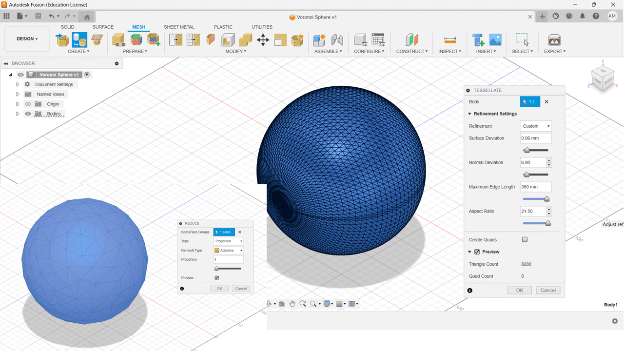
2.Switch to Mesh > Tessellate > Reduce
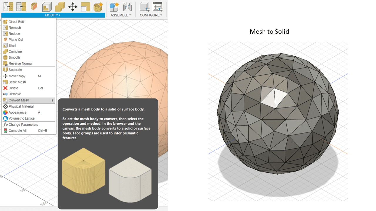
3.Click on Modify > Convert Mesh (Convert Mesh body to Solid body)
4.Switch to Solid Tab > Select Edge Priority > Create Form
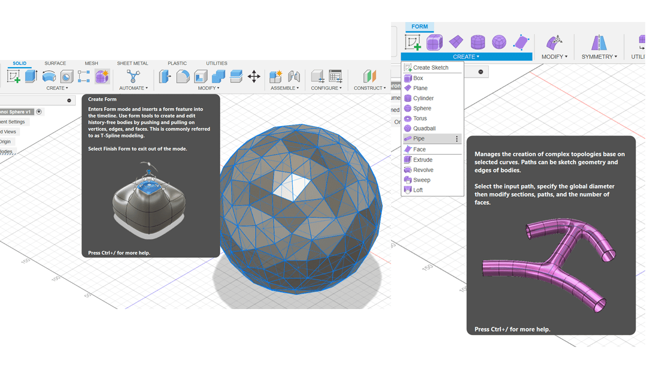
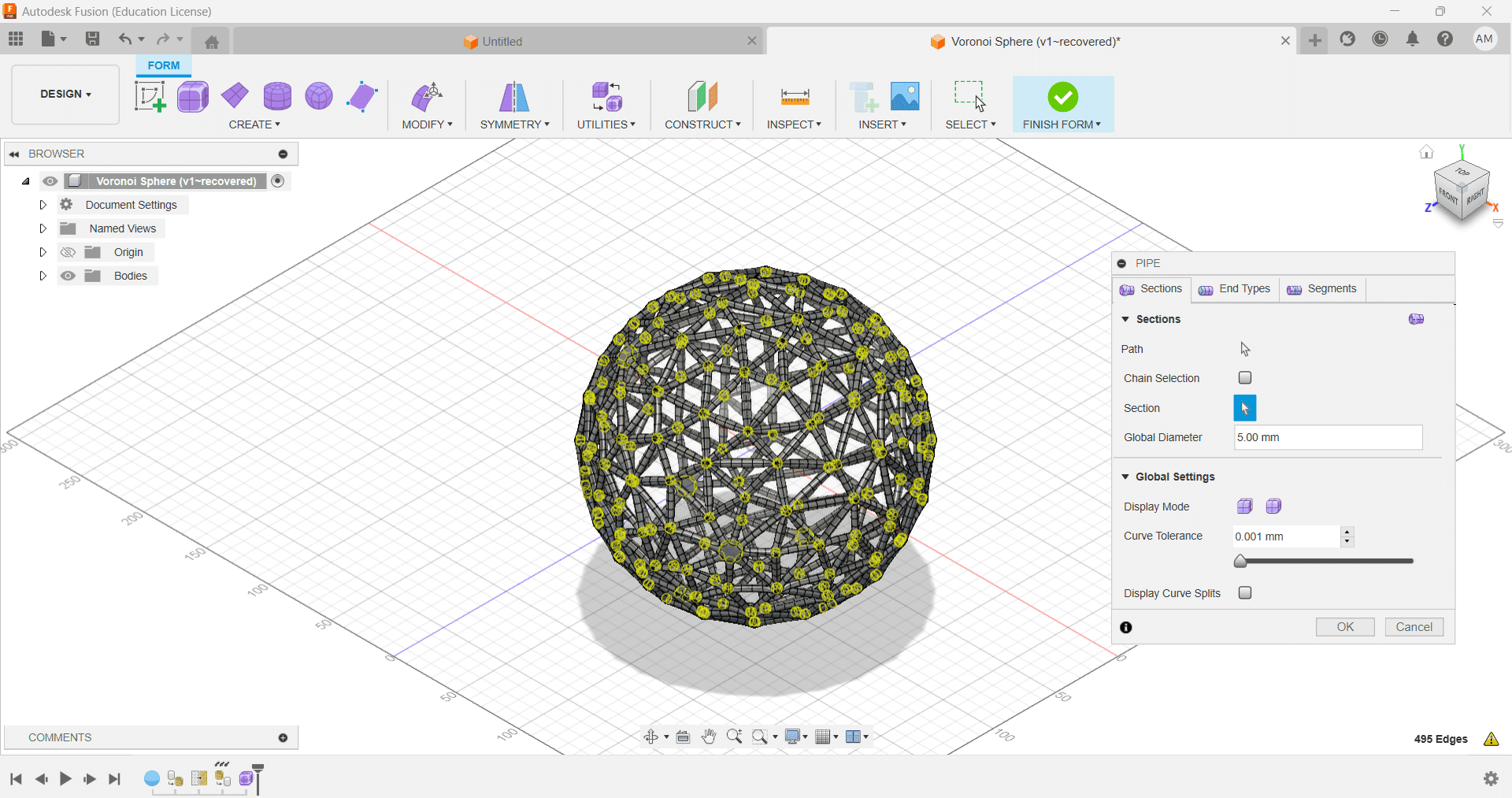
5.Select Pipe > Make Settings(Shown Below) > Finish Form
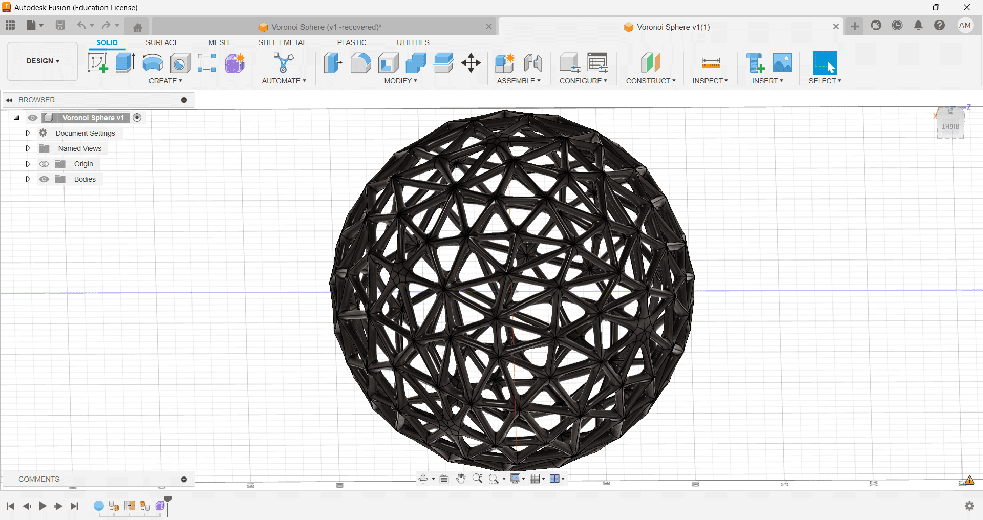
6.This is the Final Model Looks Like
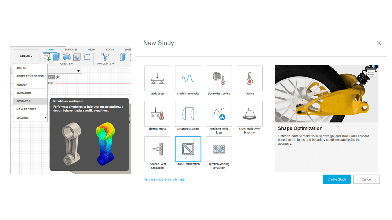
Shape optimization is the process by which we can remove unwanted material from a component by performing stress analysis on it. Shape optimization is part of the field of optimal control theory. we can save the material using this process because we are able to remove material where is less stress is applied
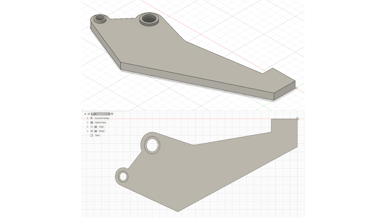
In the Design tab, I have created a model of a Gripper Arm.
I switched to the Shape Optimization tab, clicked on New Studies, and selected the Shape Optimization option.
Next, I defined the modeling constraints by navigating to (Simulation workspace > Setup tab > Constraints panel > Structural Constraints). I applied the Pin constraint to the inside surface of the bolt holes in both the radial and axial directions.
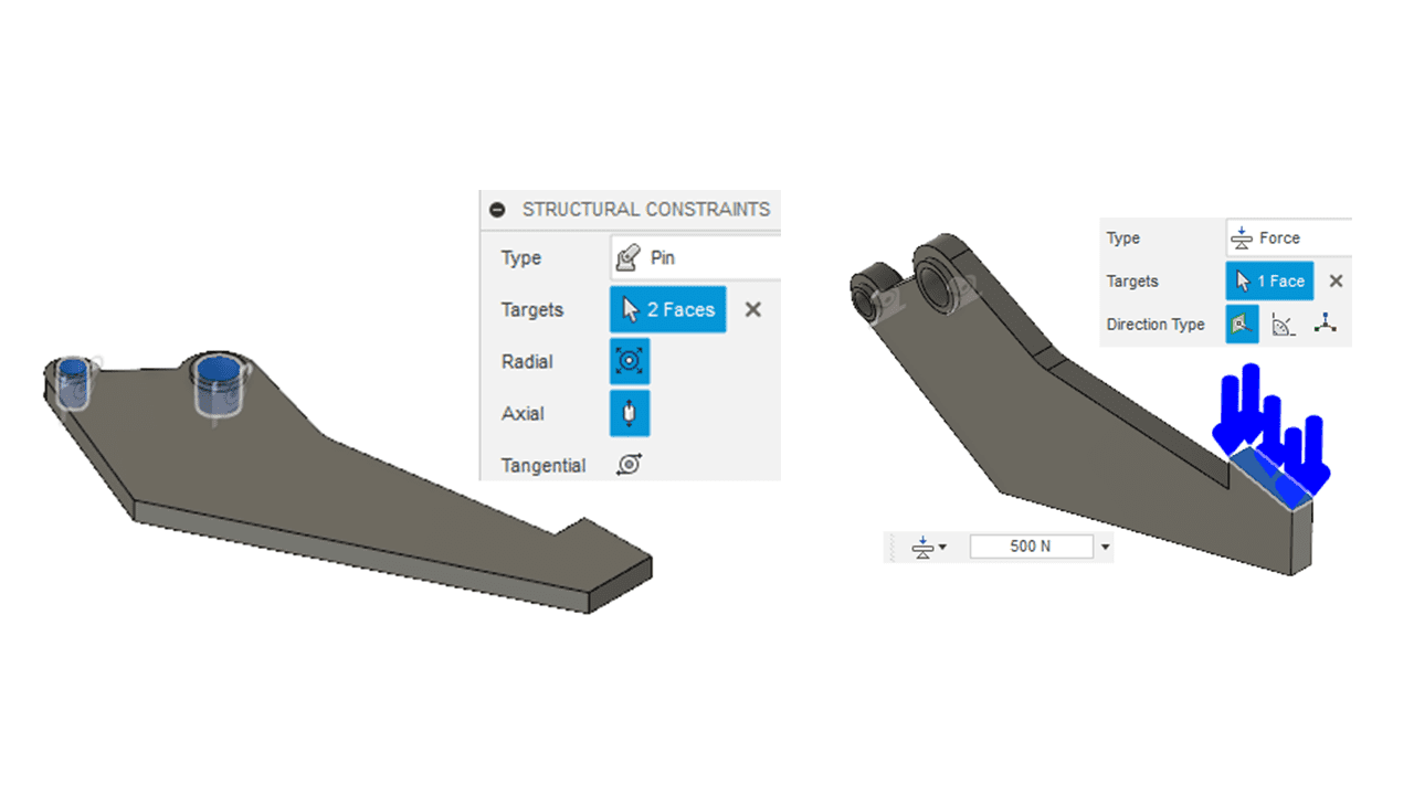
For the force application, I applied a 500N force in the normal direction of the gripping surface. To do this, I went to (Simulation workspace > Setup tab > Loads panel > Structural Loads).
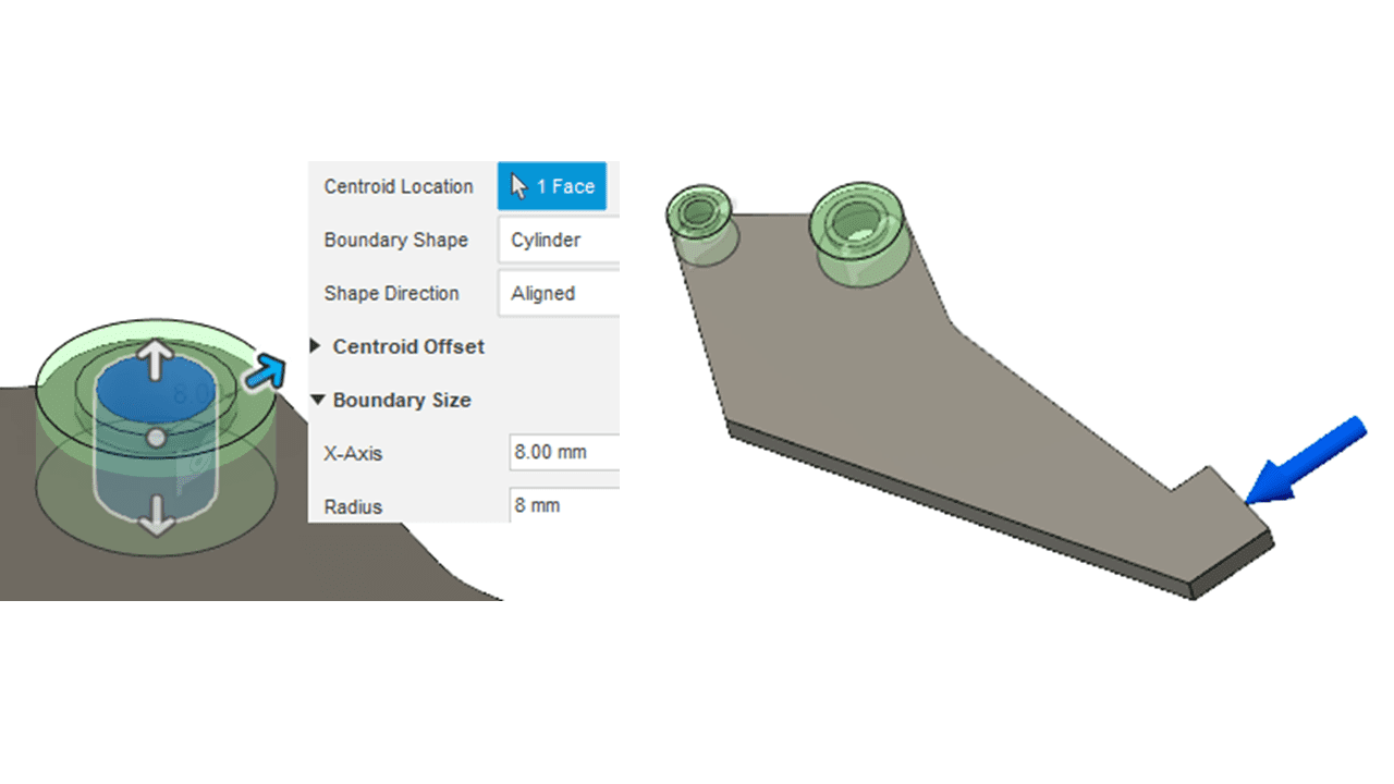
To ensure proper material strength, I preserved an 8mm distance around the large hole and a 5.5mm distance around the small one. This was done in the (Simulation workspace > Setup tab > Shape Optimization panel > Preserve Region).
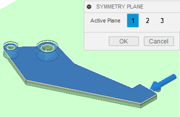
For symmetry in the optimized shape, I created a symmetry plane through the thickness. To achieve this, I went to (Simulation workspace > Setup tab > Shape Optimization panel > Symmetry Plane).
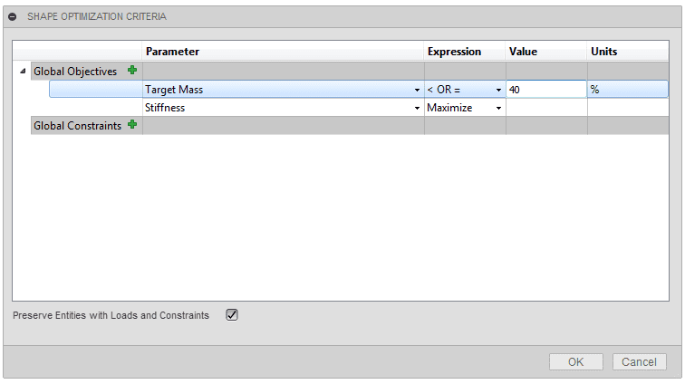
The shape optimization target mass was set to 40%. This setting is found in (Simulation workspace > Setup tab > Shape Optimization panel > Shape Optimization Criteria).
A crucial step involved setting the shape optimization criteria and solving the study. To do this, I navigated to (Simulation workspace > Setup tab > Manage panel > Settings). I also reduced the mesh size by IMM, then clicked on Solve Study in (Simulation workspace > Setup tab > Solve panel > Solve) to finish the study.
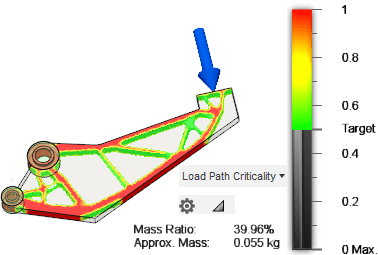
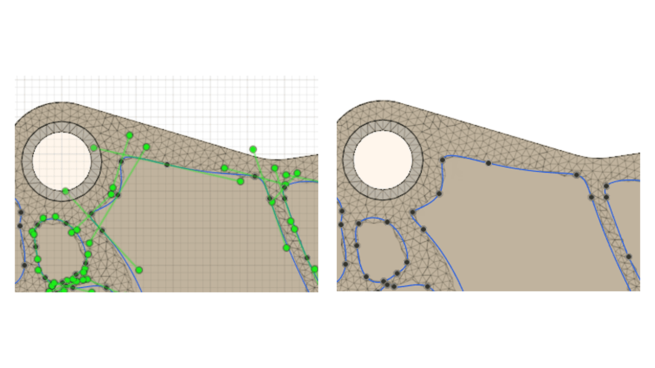
I obtained Load Path Criticality results.
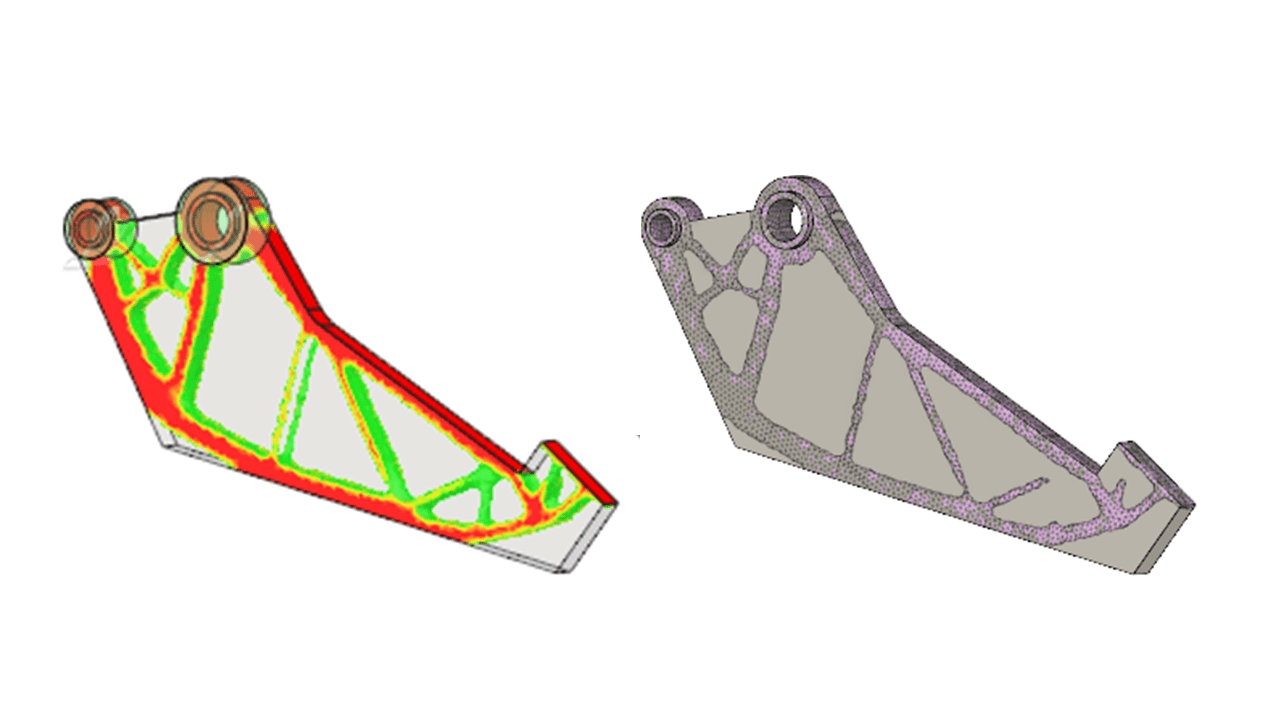
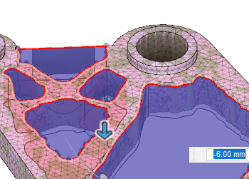
I exported the mesh to the design workspace and drew splines and lines on areas with lower stress to create the final model.
I extruded cut the design, upgrading it using the shape optimization study.
I then cloned the shape optimization study by going to (Simulation workspace > Setup tab > Manage panel > Settings) and switched the Study Type to Static Stress. Afterward, I clicked on Solve Study in (Simulation workspace > Setup tab > Solve panel > Solve).
It is crucial to check the factor of safety, ensuring it meets the minimum requirement. To do this, I went to (Simulation workspace > Results tab > Inspect panel > Show Min/Max).
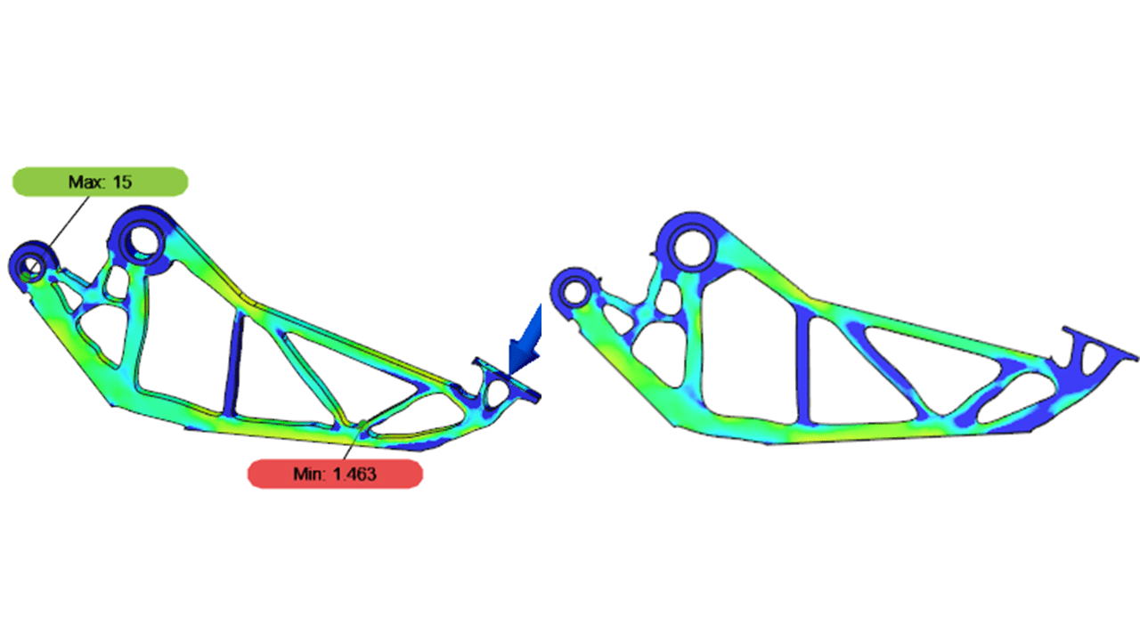
The static stress study was performed with the objective of reducing the part's weight to approximately 40% of the original and maximizing stiffness. A stress analysis is necessary to verify that stress and displacement in the modified part shape are acceptable. The generated shape must have a safety factor of at least 2.0. If the factor of safety is greater than 2, it indicates that the part can withstand the applied load and is suitable for manufacturing.
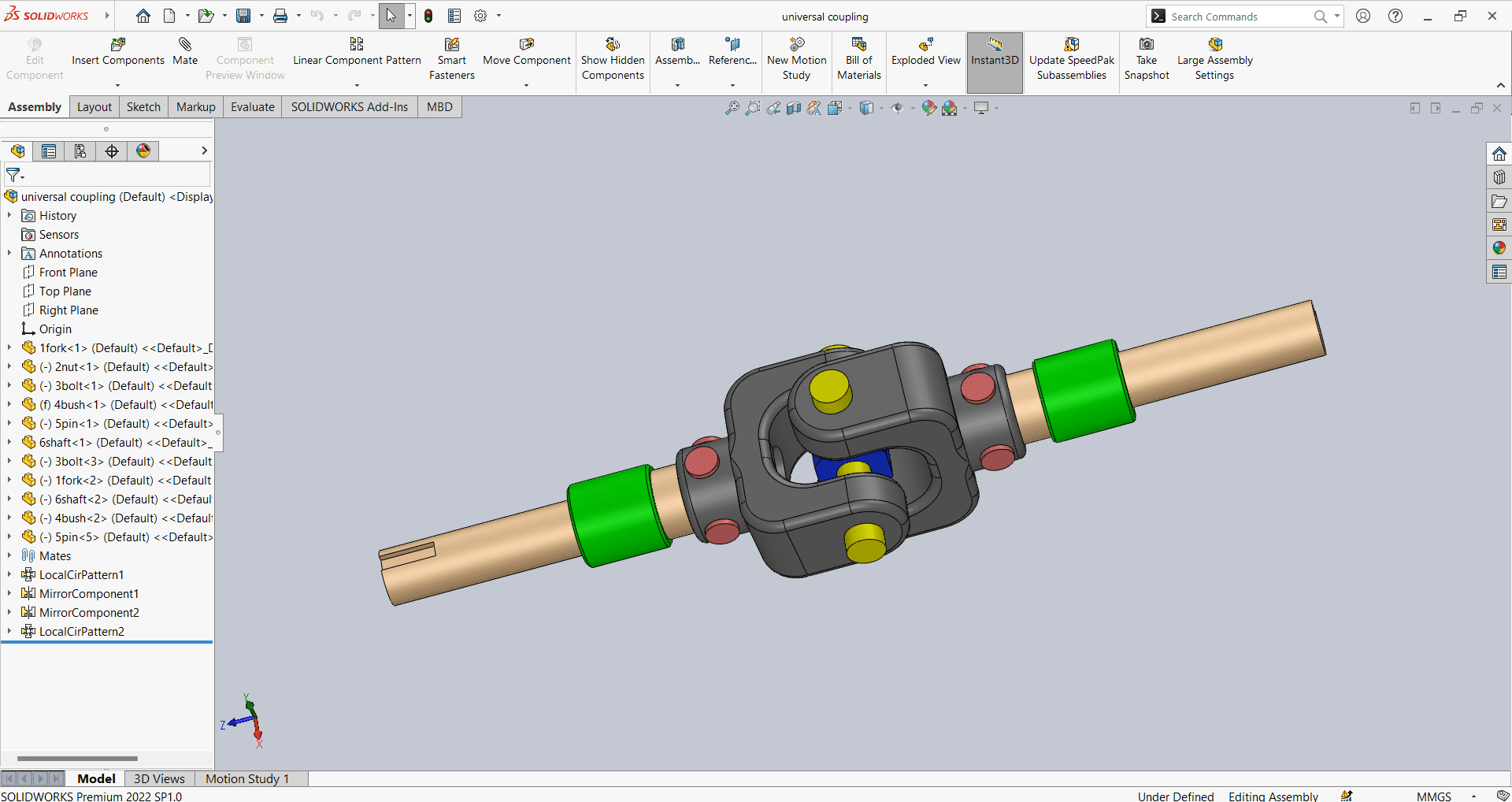
In SolidWorks, I have designed a Universal Coupling by creating various parts such as a shaft, fork, nut, bolt, bush, and pin, along with their assembly. Throughout this process, I learned about different sketch commands and features in SolidWorks. Additionally, I gained knowledge on making mates in assembly and how to constrain different components.
Commands I have used in SolidWorks
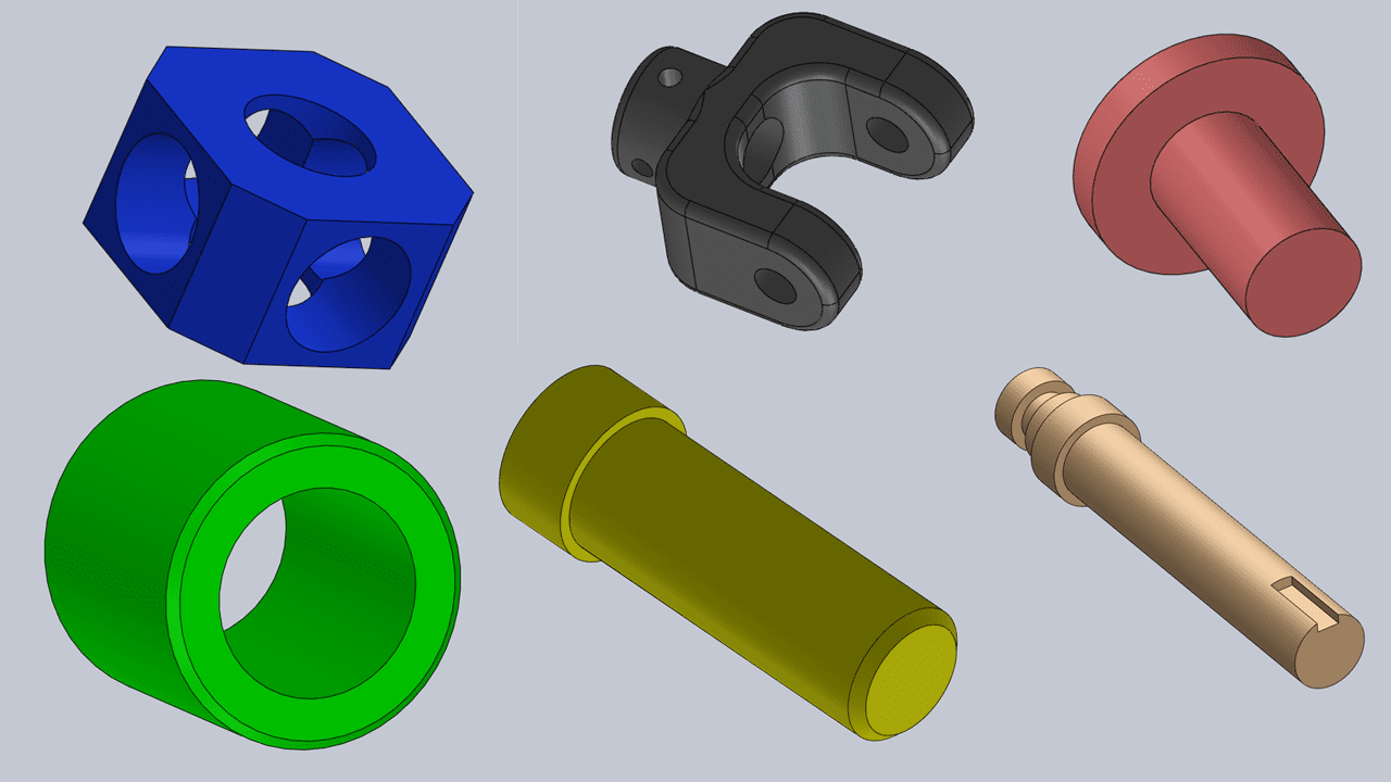
These are the parts of the Universal Coupling
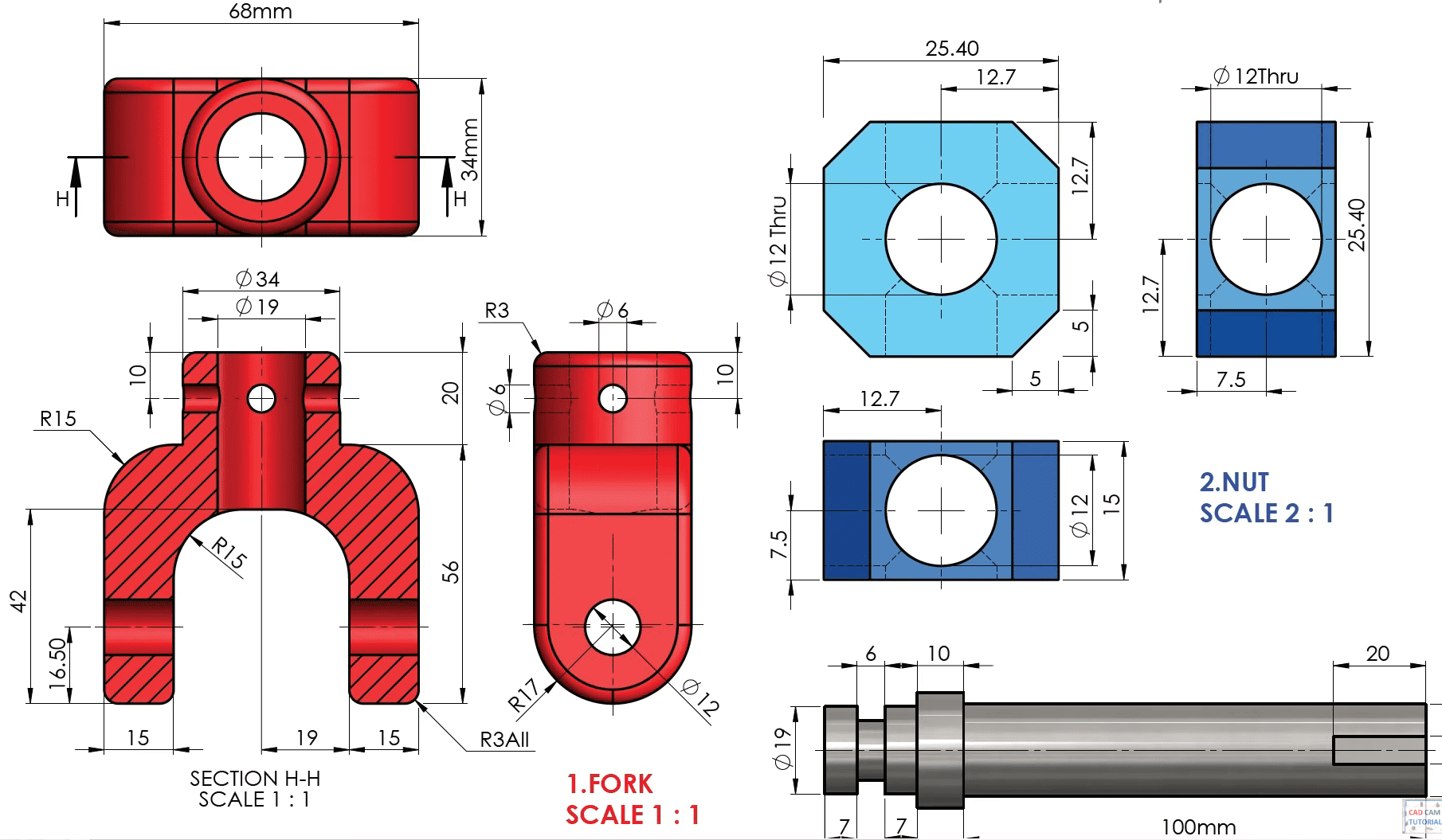

Firstly, I selected the part to design the 3D object. Within this, there are various options such as features, sketch, and more. I opted for the sketch option to begin drawing on the fork. I used the dimensions as shown in the image above.
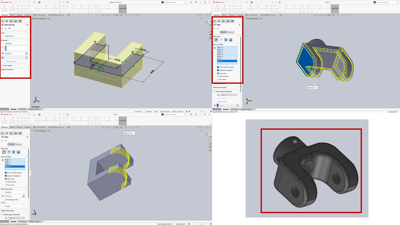
After selecting the 'extrude' option within the features menu for solidification or 3D viewing of the part, I began from the mid-plane. Following that, I utilized the 'fillet' tool to create soft and rounded corners for the component. I applied various fillet radii, such as 3mm, 17mm, and 15mm.
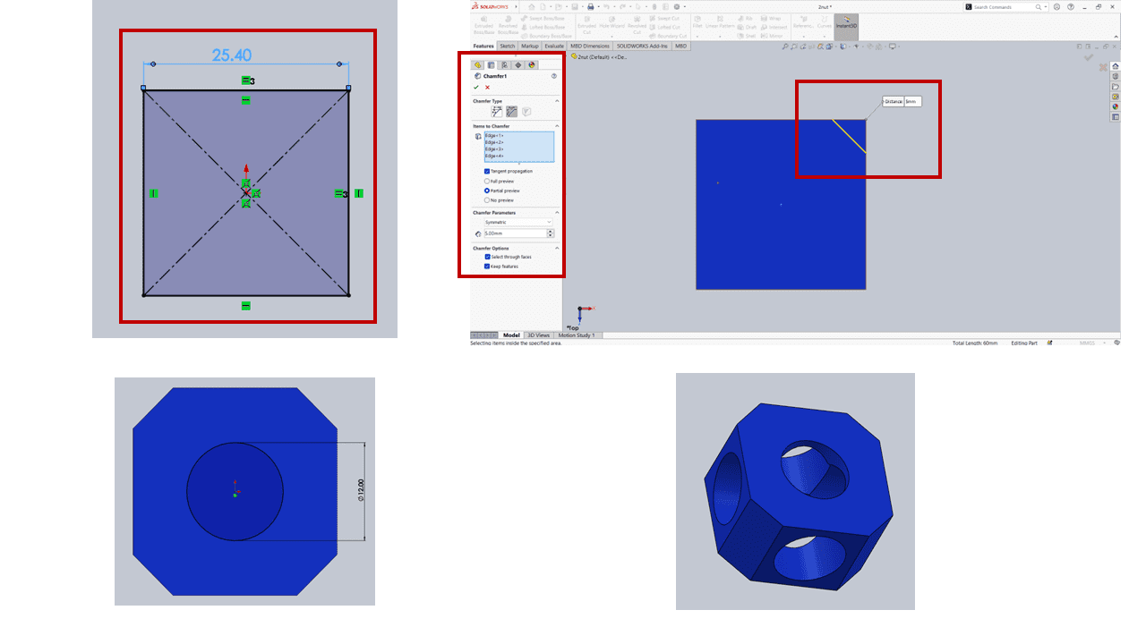
For the next part, the nut, I utilized the dimensions mentioned above, where I took a square of 25.40 mm. Then, I chamfered all the edges of the square by 5 mm before extruding it. Afterward, I made holes on all faces of the nut with a radius of 6 mm.
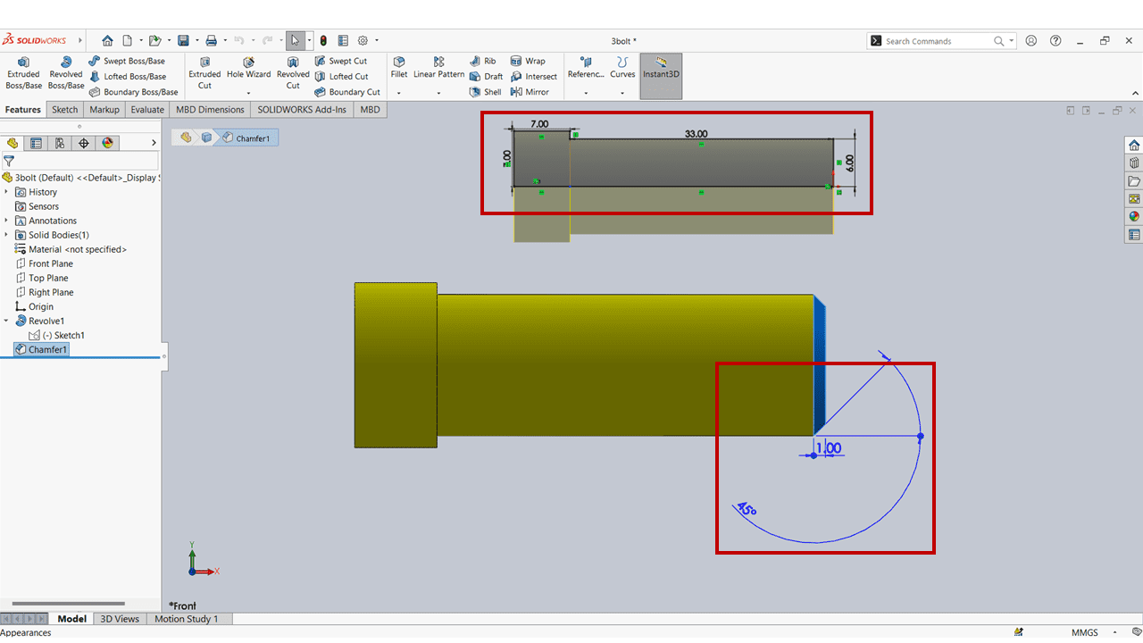
For the design of the bolt, I simply created a sketch using the dimensions provided above. Then, I employed the 'revolve' command to give it a cylindrical shape. Additionally, I utilized the 'chamfer' command at the beginning of the screw, setting it at an angle of 45 degrees and a distance of 1 mm.
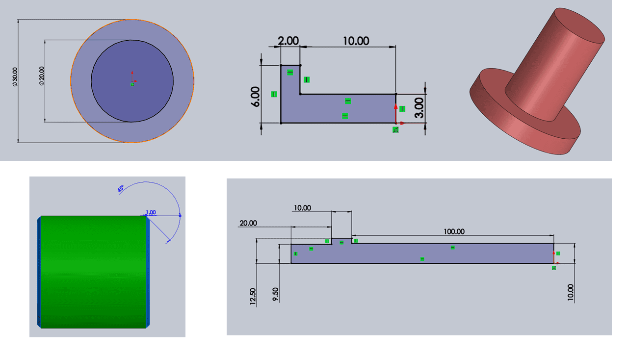
For the pin and shaft, I applied the dimensions mentioned above and utilized the 'revolve' command to create a cylindrical shape. Additionally, I chamfered the pin at a 45-degree angle and a distance of 1 mm.

I assembled all the parts using the assembly option, inserting each component one by one and applying proper mates using commands such as concentric, parallel, and coincident. The final outcome is depicted in the image above, and a 3D representation is provided below.
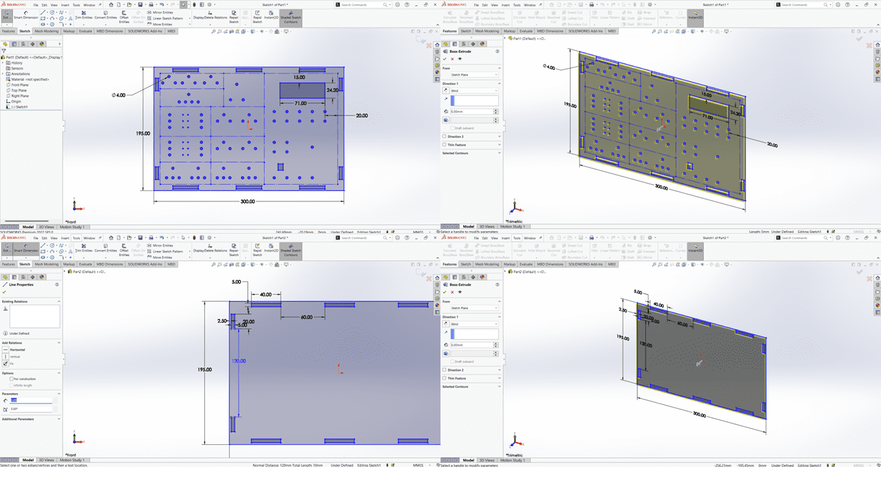
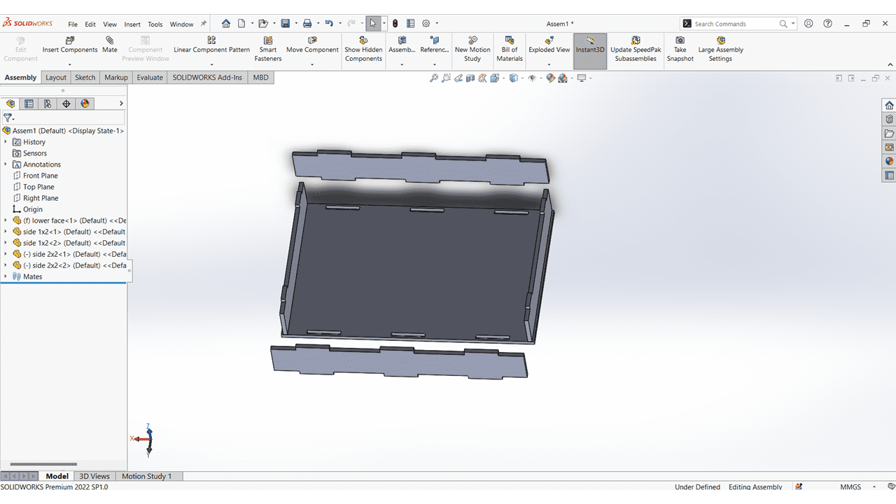
This is the upper and the lower faces of my electronics learning kit.
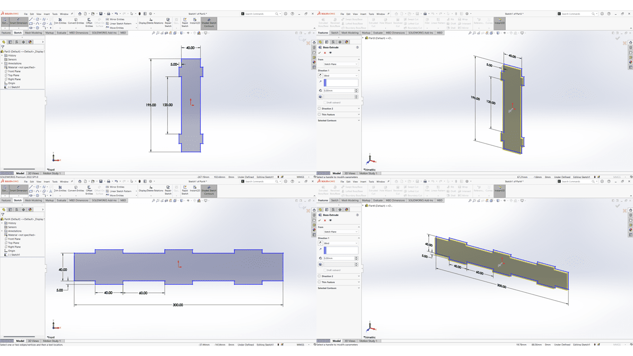
This is the Vertical and Horizontal sides having the thickness of 5mm each.
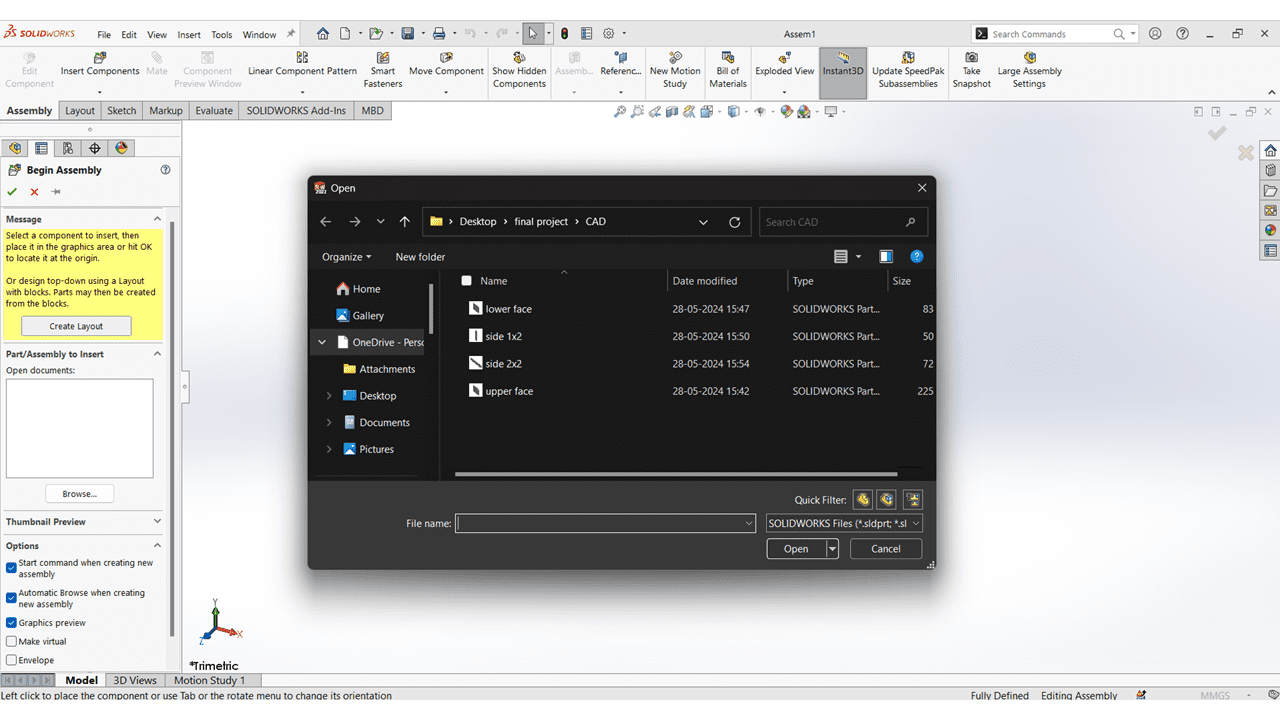
After that used the Solidworks Assembly option for making the Assembly of all the Parts.
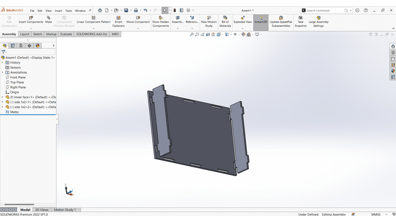
I mate all the Vertical Faces with Lower Face.
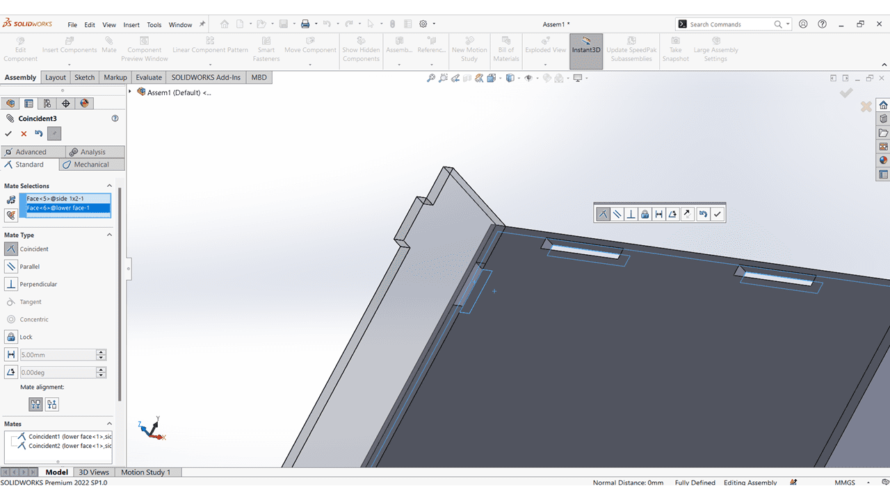
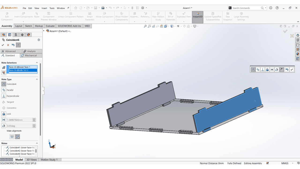
I mate the Horizontal Faces with Lower Face.
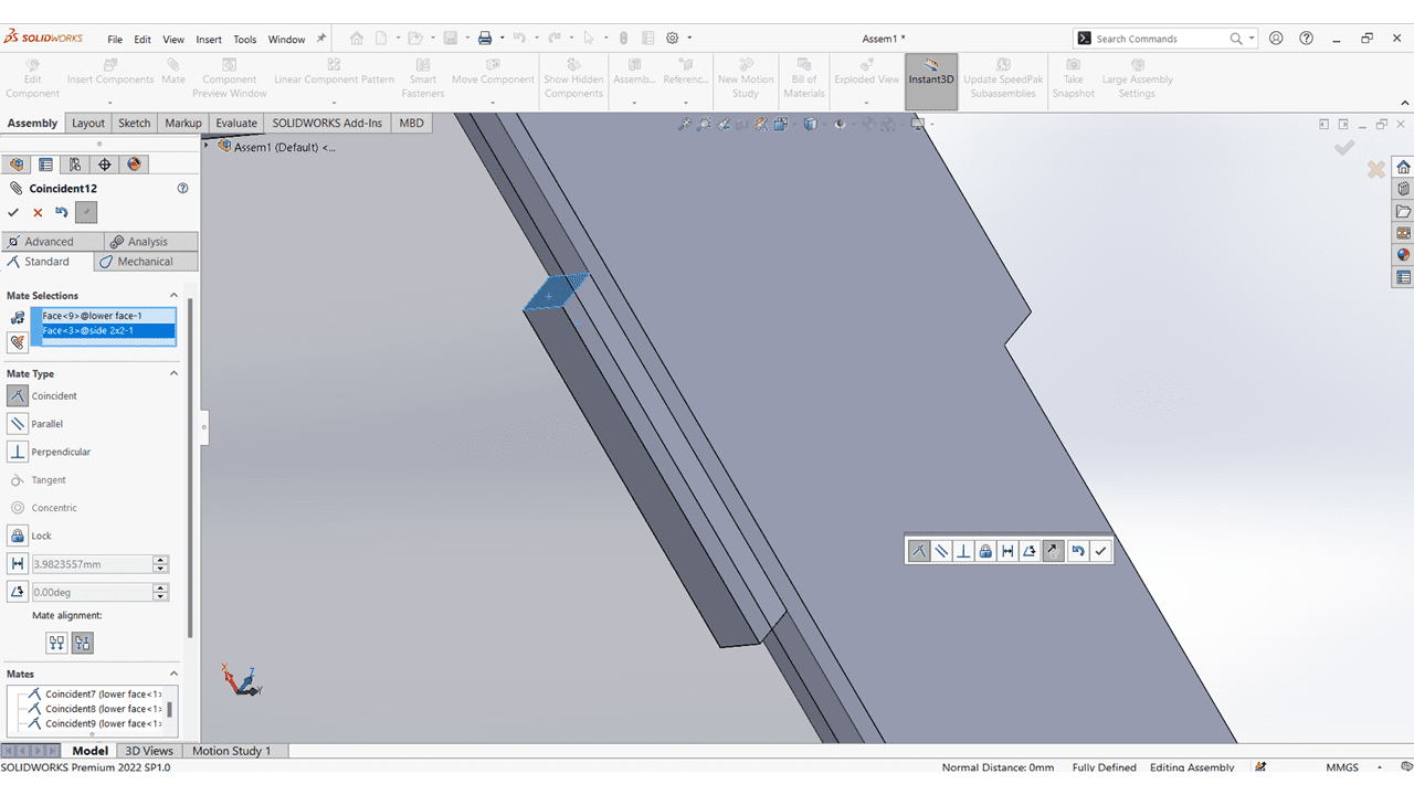
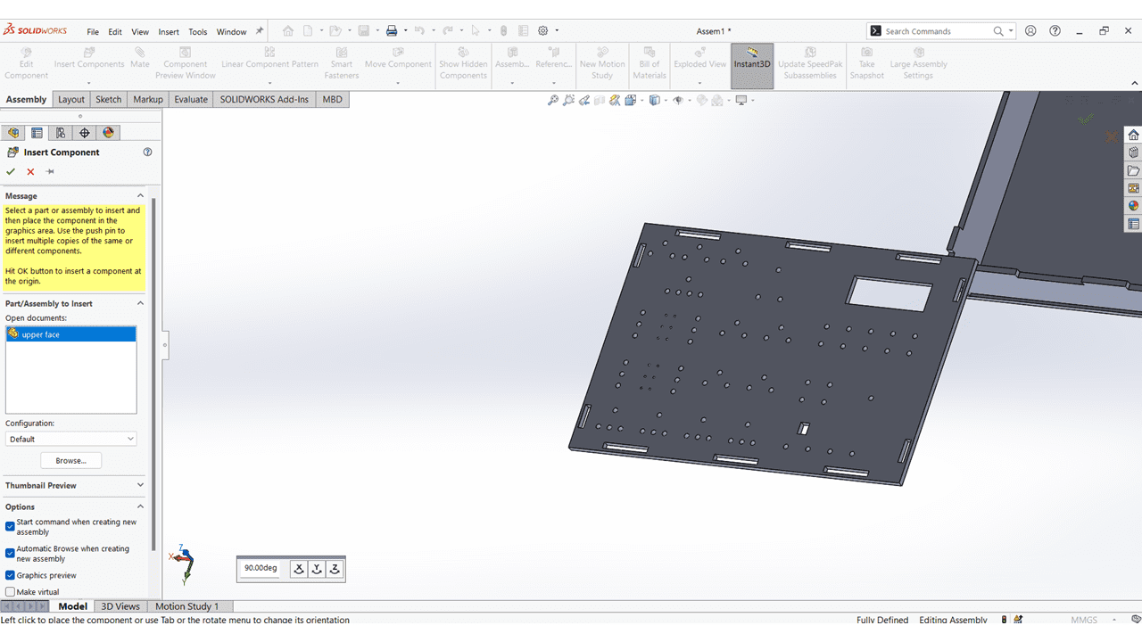
I added upper face of the kit and mate it with the slots.
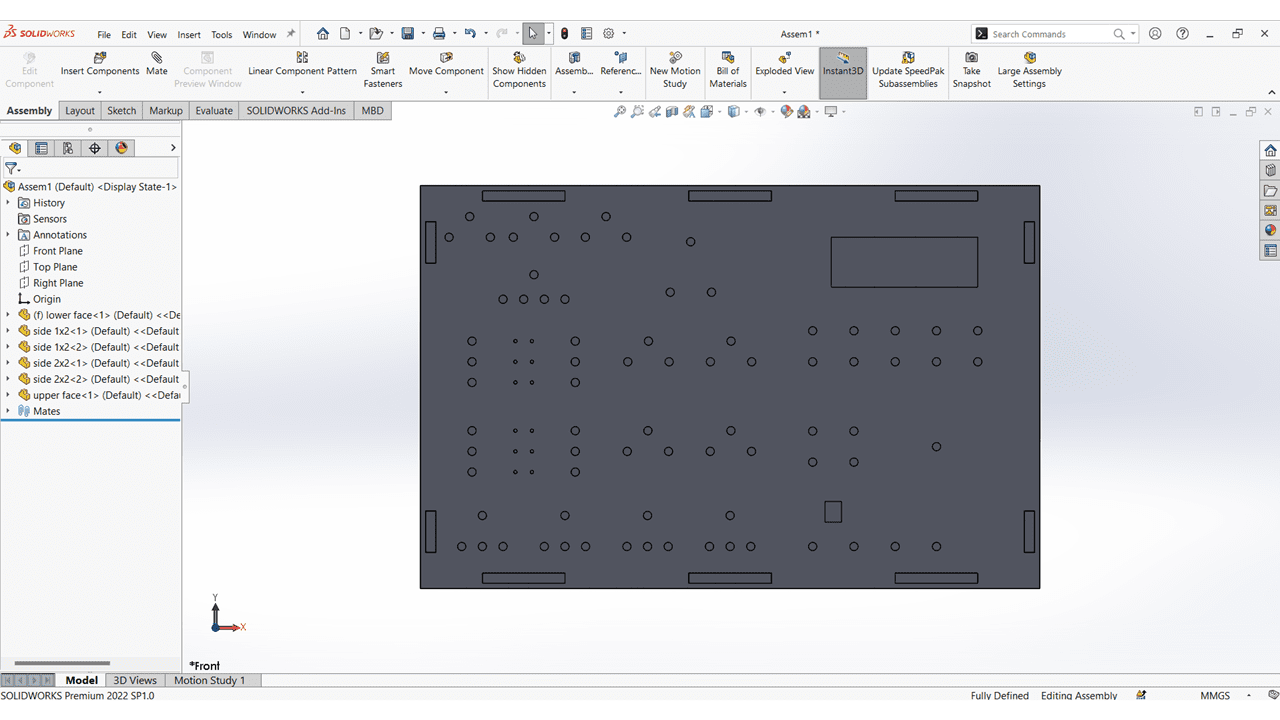
This is the TOP view of my Elctronics Learning kit.
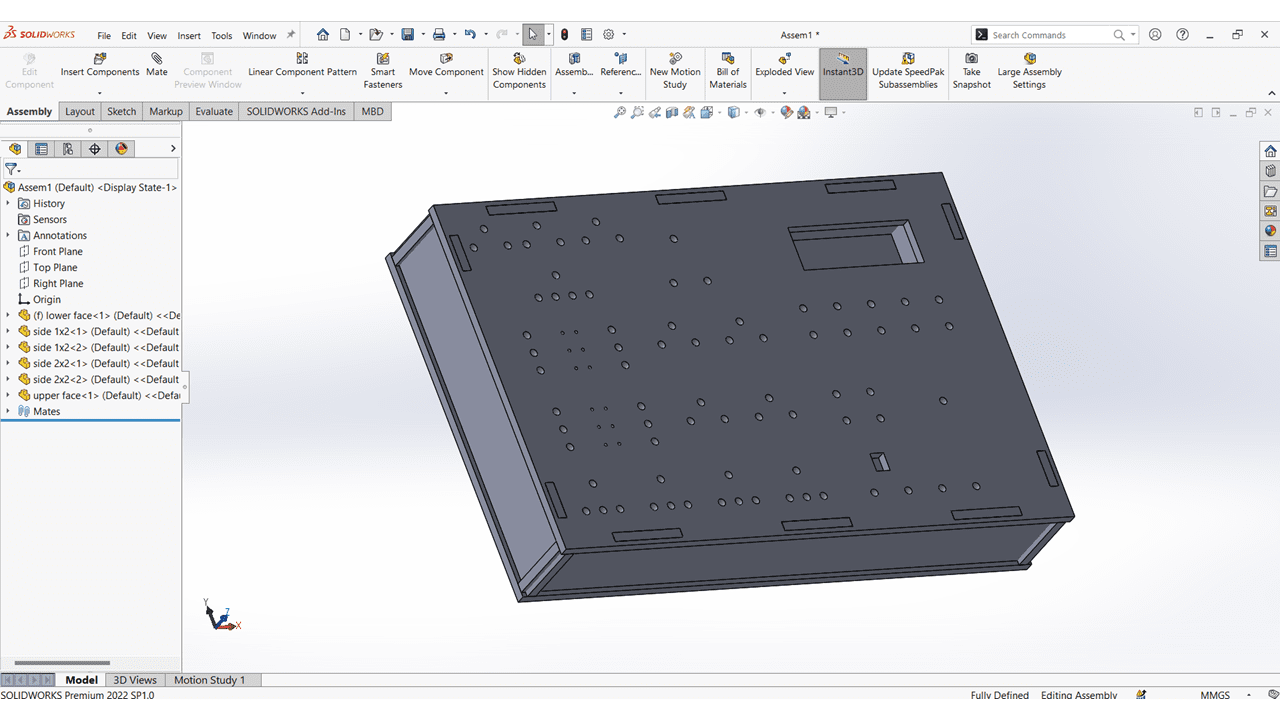
Isometric view of my project
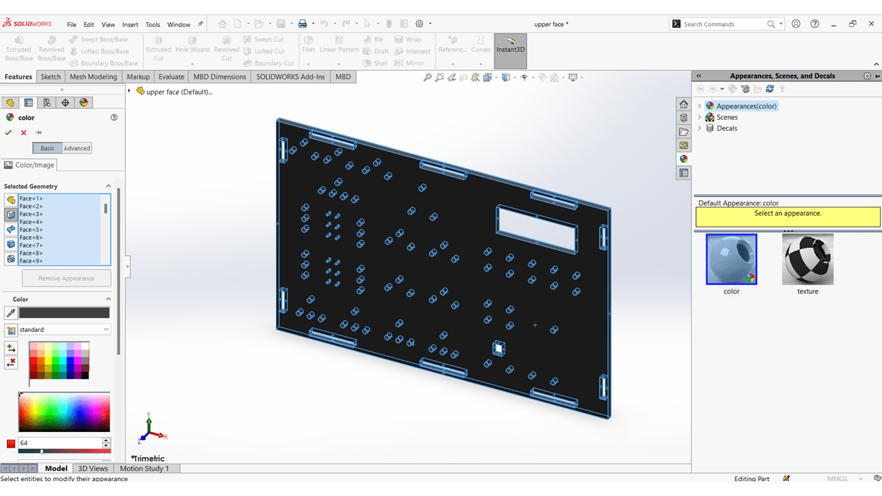
I coloured all the parts.
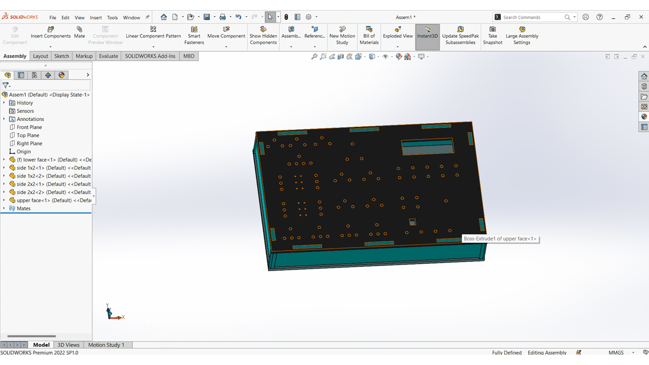
This is the Casing of my Electronics Learning kit.
I used the FFMPEG as a video compression tool for my videos
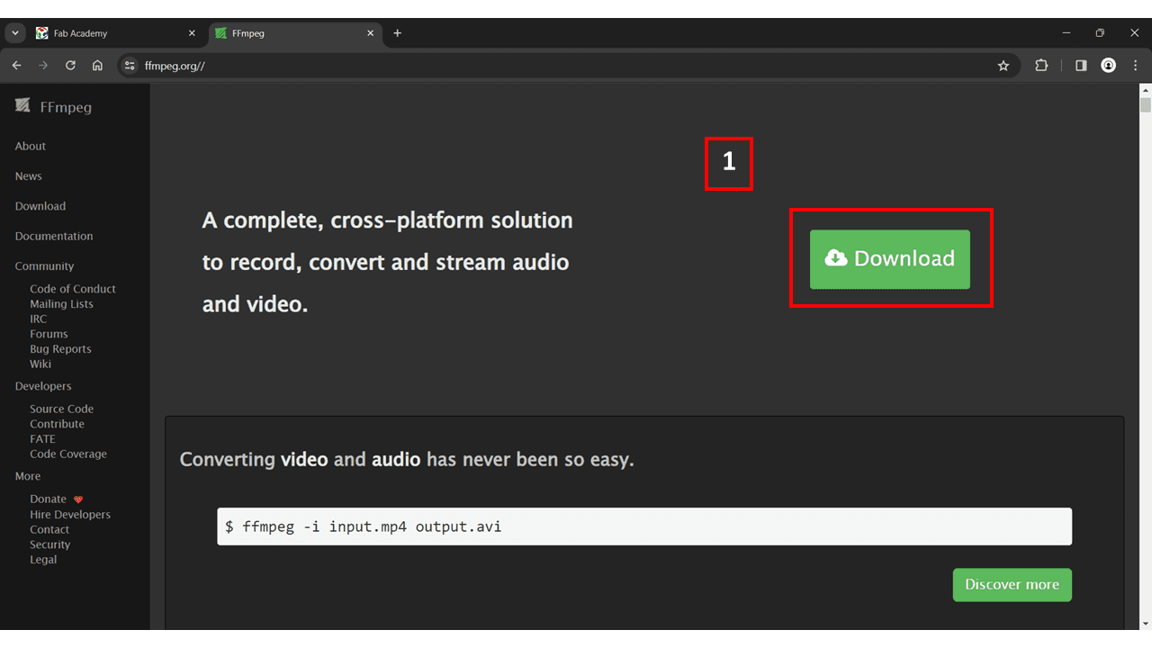
I have downloaded FFMPEG from their official website
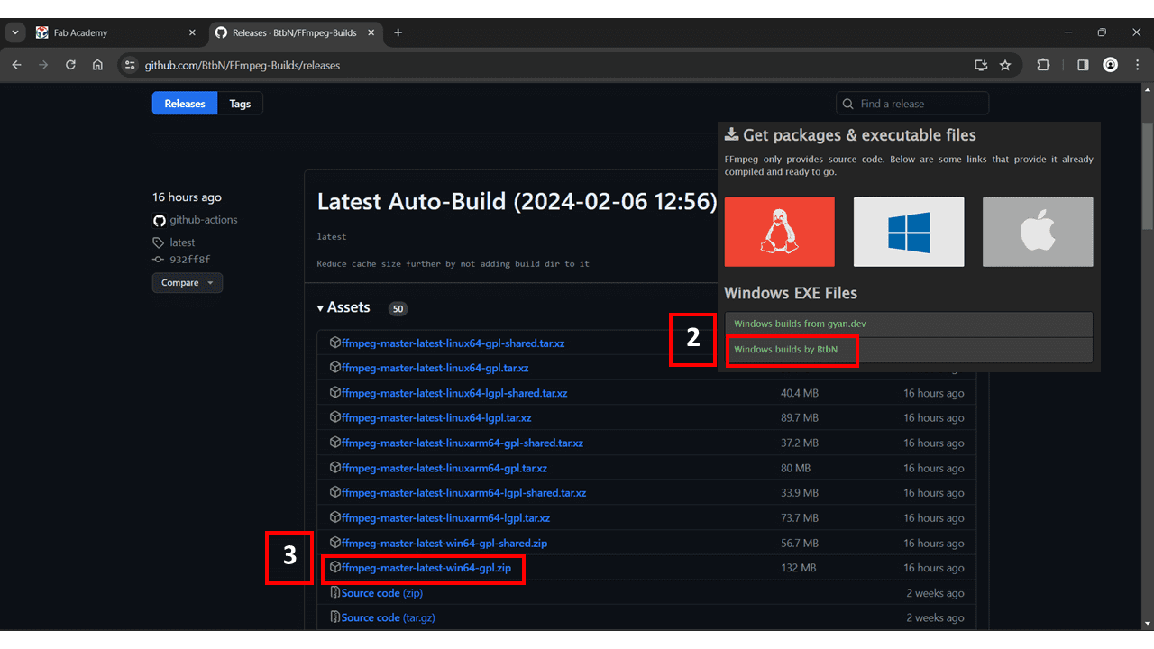
I selected the Windows option, and from there, I chose 'Windows builds by BtbN. I downloaded the ffmpeg-master-latest-win64-gpl.zip file, which has a size of 132 MB.
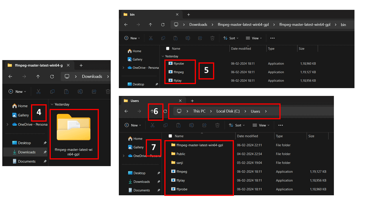
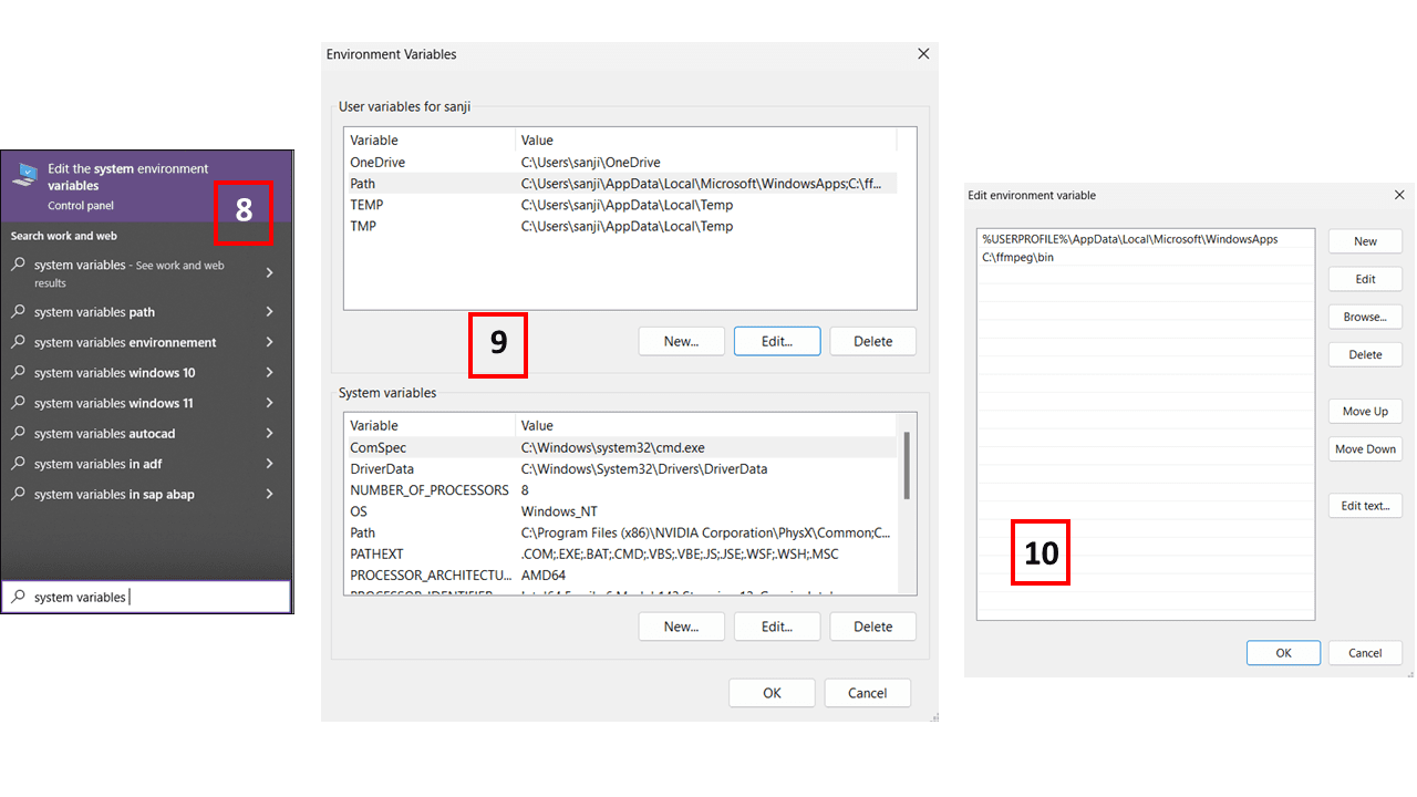
Next, search for 'System Variables' and edit the variable named 'Path', then add the path 'C:\ffmpeg\bin'.
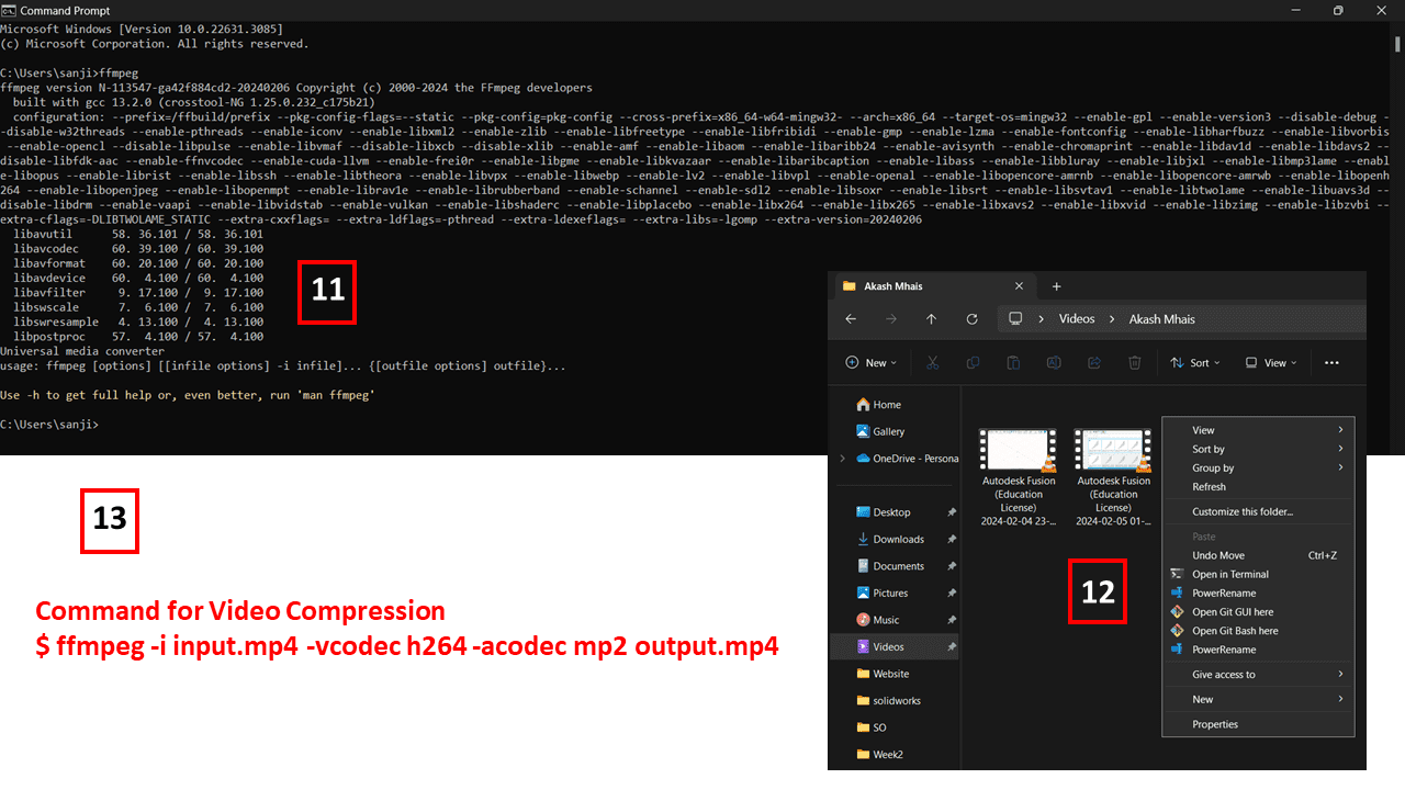
Open Command Prompt, then type 'ffmpeg' and press Enter to install ffmpeg. Next, navigate to the folder where the video is stored, right-click, and choose the 'Open Git Bash here' option. Then, use the command '$ ffmpeg -i input.mp4 -vcodec h264 -acodec mp2 output.mp4'. Replace 'input.mp4' with the name of your video and 'output.mp4' with your desired output filename.
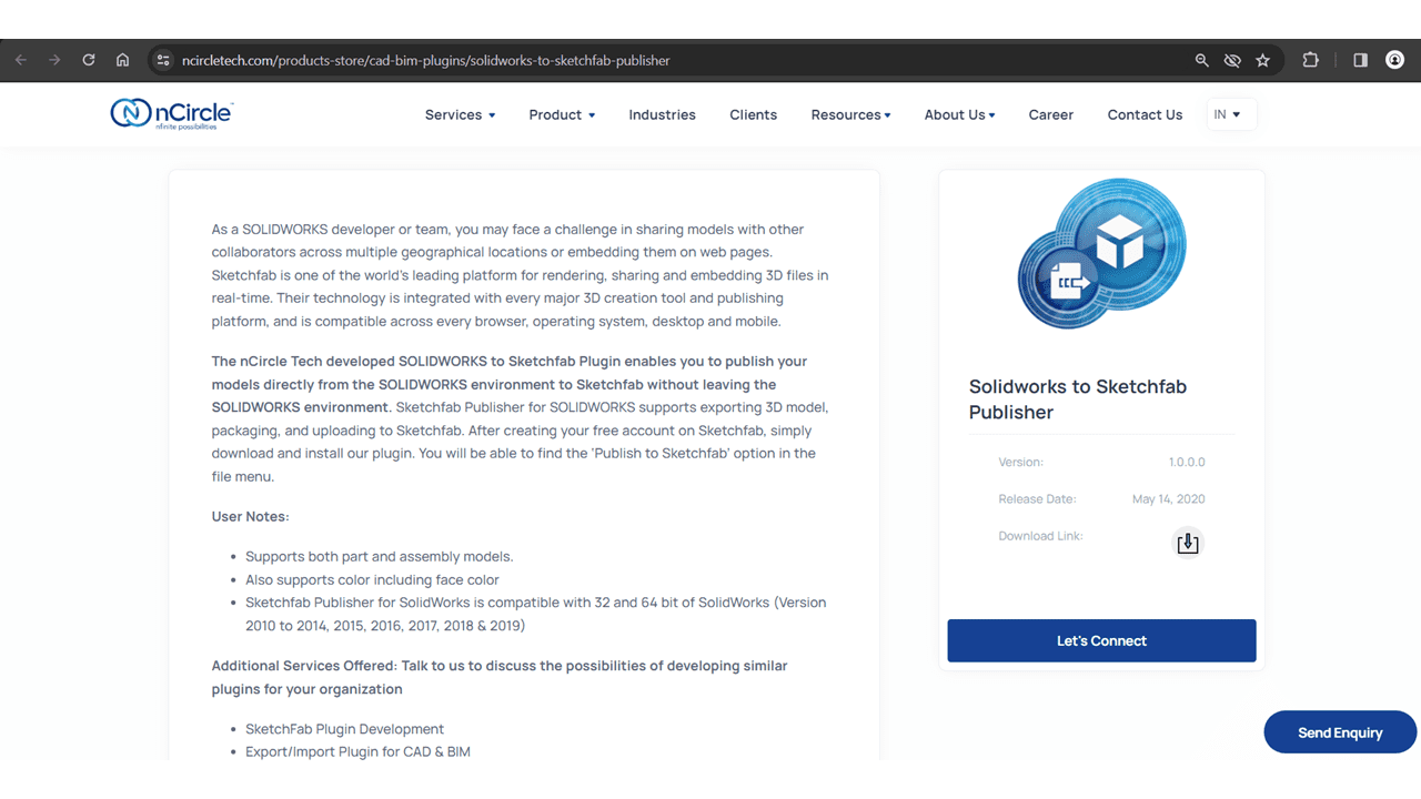
I used the Sketchfab for showing the 3D Model.The nCircle Tech developed SOLIDWORKS to Sketchfab Plugin it enables us to upload the 3D Models directly from Solidworks to sketchfab cloud
After installing the plugin, navigate to SolidWorks and locate File → Publish to Sketchfab. If the option is not visible, ensure that the Sketchfab Publisher for SolidWorks is properly loaded in the Add-Ins Manager.
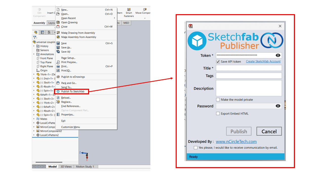
Once you find the option, click on "Publish to Sketchfab." A popup should appear; enter your API token, title, tags, description, and mark it as Private if necessary. Additionally we can get option "Export Embed HTML" which is used to generate webpage of the 3D model
After filling in all the details, click on the "Publish" button. A progress bar will appear, indicating whether the upload is completed or not.
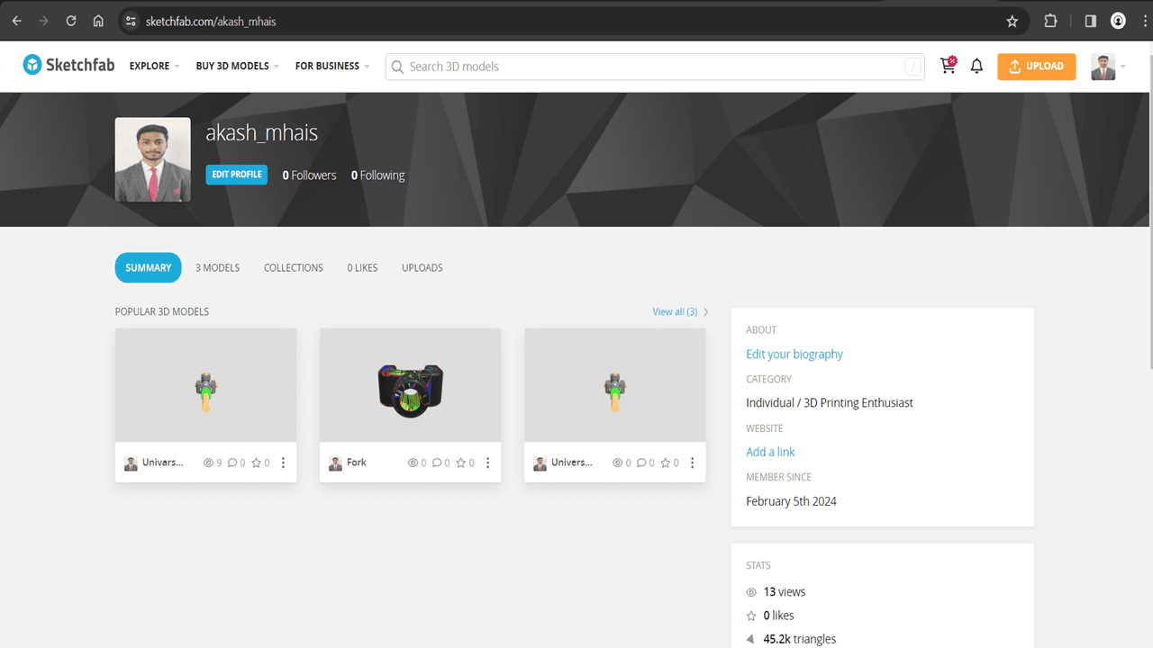
here is the object on our cloud sketchfab account
LaserCad
SOLIDWORKS to Sketchfab Plugin
SolidWorks - Universal Coupling.