12. Input Devices
This week’s documentation is broken into three parts:
1. Understanding Step Response and trying it
2. Hall Effect sensor for magnetism
3. A Reed Switch for magnetism
But first:
Group Assignment
Please find this week’s group assignment on Himanshi’s Page. Search for Group Work heading.
We used the oscilloscope to read the signals of a sound detection sensor. We saw that the sound sensor gives a wave that was fluctuating with the sound level. So if I blew air into the sensor and/or spoke really loudly into it, I would see a magnification in the amplitude of the wave generated.
Step response
As a part of our Design curriculum in college, I have used sensors such as ultrasonic, touch sensor, PIR and a few more. These I have used with the Arduino UNO board and it’s been well over a year now.
So today, I decided to begin with the most interesting of them all- Step Response!
I delved a bit into understanding what Step Response was i nthe first place, as I was a bit confused. I rewatched the class video recording and looked at Jesal Sir’s documentation where he further links to other pages, which I will link in a bit.
From what I’ve understood:
- When you apply a small potential difference between two disconnected copper plate, a electro-magnetic field is generated between them. This field has a value and a direction. (If the potential difference is really REALLY high, then there will be lightning! xD )
- Now, when you introduce an object which disrupts the EM field, such as your finger, or any other object, you can actually measure how much the disruption is, i.e., the difference in the conductance between the plates. This is shown in the plotter on the Arduino IDE.
- Lastly, you can use this disruption to measure touch, force, pressure, rotation, and location!
I also did this little shenanigan:

And then I asked it to further explain it in basic terms, to which it replied:
“Sure, think of a step response in electronics like turning on a light switch. When you flick the switch, there’s a tiny delay before the light actually turns on, and then it brightens up gradually instead of instantly becoming super bright. That’s the step response in action.
In electronics, the step response is how a circuit reacts when you suddenly change something, like applying a voltage or turning on a signal. It shows how fast the circuit starts doing what you want it to do and how smoothly it does it. This helps engineers understand and design circuits that work reliably and predictably.”
And so I decided to try step response for myself.
For the first few days, I was sick and so was working from home. This meant that I had access to only a limited number of equipments and that milling a PCB would not be possible. So I reffered to Jesal Sirs’ work to understand the schematic of the connections.
I drew my own in my notebook:
Next, I took a breadboard I had at home along with a few jumper wires and connected it to the pins of my own devlopment board. (Thankfully I carried my stash of milled PCBs with me everywhere I went)
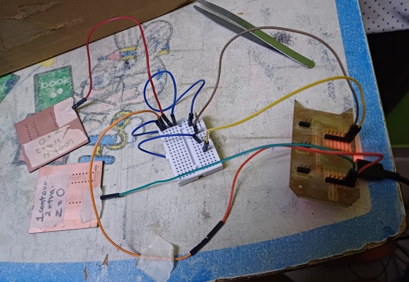
And on running the code and tapping the two copper plates, I got the following response:

Next up, my health got better :D
So I began replacing the breadboard with a PCB.
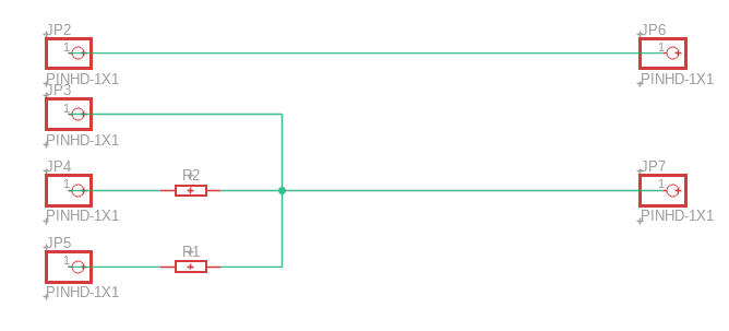
I made the circuit on Fusion 360/Eagle:

And the milling began:

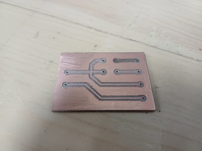
For the copper plates, I reused old PCB stock which had been milled incorrectly.

Final outcomes:
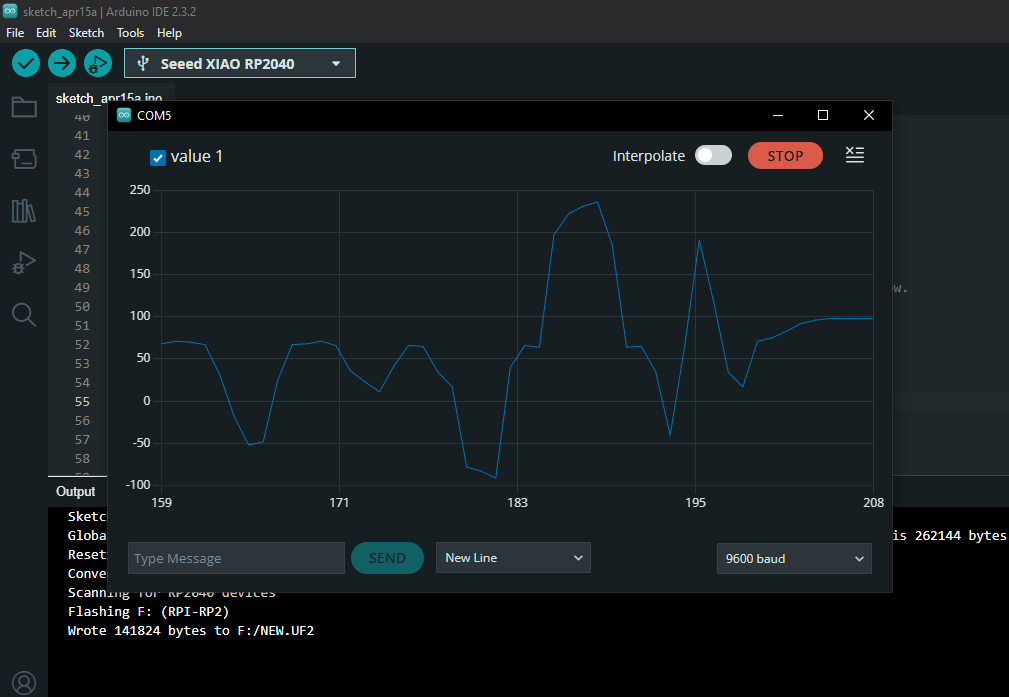
Touching the bottom plate, the graph rockets to 230 from 160-170:
Touching the top plate, the graph dips to -100 from 150:
Touching both at the same time, the graph rockets drastically to 1100:
Varying distance between the plates:
Applying pressure using a roll of masking tape:
Varying the twist angle between the plates:
Hovering my hand over the plate:
As seen, step response is a really cool thing. The next step would be to caliberate these readings precisely and essentially end up with a input device for anything!
Hall Effect sensor
I used the Hall effect sensor module to test for magnetism.
I wanted to use something similar in my final project and so decide to explore this sensor.


I connected the sensor to my development board in W8 as per the naming of the pins.

Next I brought a magnet closer to it to see if anything happened.
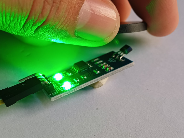
The LED tunred ON as I brought the magnet close and it turned off as the Magnet was taken away.

Reed Switch
A Reed Switch essentially works on magnetism too. It is a a switch encased in a tiny glass tube. When you bring a magnet nearby, the switch opens due to the magnetic force.
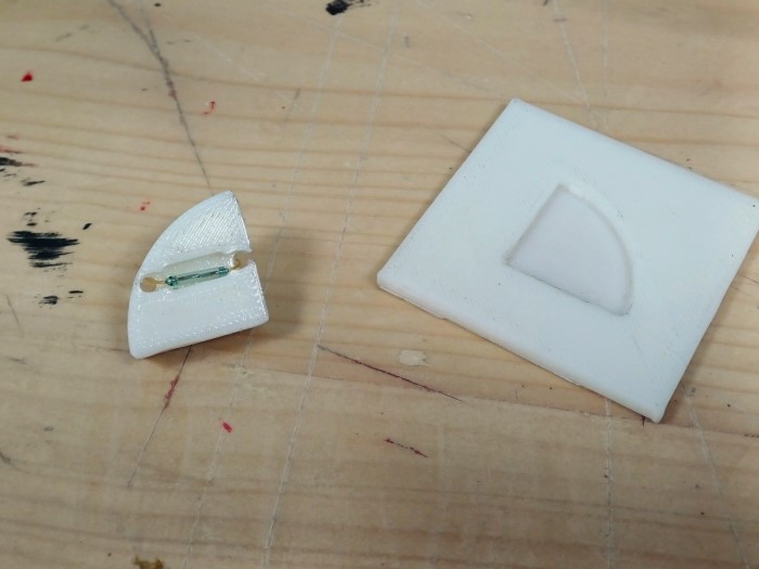
I used these in my final project. However, since they are made of glass, they kept breaking!