4. Electronics Production- A Series of Unfortunate Events
This week is dedicated to making PCBs and soldering basic components. The PCB to be made is the Quentorres. You can find the design files as well as other details of the Quentorres (shortform: QT) board on the link given.
To our dismay, this week we were faced with a lot of difficulties (and hence the title):
I am (not) Lemony Snicket, and let me recite to you the story of the Boardelaire twins. In my version of the story, there are two twins. They’re names are:
- Lysander Percival Krinklesnatch-Foxworth
- Seraphina Rosemary Montague
Lysander Percival, or simply Percy, was 5 years old. Much like his father, he had a young sharp mind and a growing interest in electronics. He would take sheets of tasteless metallic copper and bite into it in his free time- creating bizarre patterns on the copper sheet. Of course, he was immune to the metal.
Seraphina Rosemary, or simply Rose, was 8 years old. She too was an inventor from birth- always playing around with wax, metal, and even soft wood! Little did she realize that her talents of multiple things would help her be of aid to three lost and curious souls.
The lives of these twins were up for a complete makeover when they enrolled into the Fab Academy.
Hehe,
So, Lysander Percival Krinklesnatch-Foxworth obviously refers to the LPKF E44 Protomat
And Seraphina Rosemary Montague refers to the Roland monoFab SRM-20.
To better understand this week, I’ve divvied out the documentation into the following categories:
-
LPKF E44 Protomat:
- Understanding the machine and learning its operation
- Machining the PCB- FAIL
- Debugging and the Line test
-
SRM-20:
- Learning operations
- Trials and errors to set up the corrent setting
- Final milling SUCCESS!
-
Soldering:
- Trials and errors
- SUCCESS!
-
Testing QT
-
Sending a PCB design to a board house
1. LPKF E44 Protomat: [Done as group]


Understanding the machine and learning its operation
We started by learning about the PCB machine (our first try, the LPKF).
We knew we wanted to manufacture the Quentorres so we had the zip file downloaded and ready to run on the system.
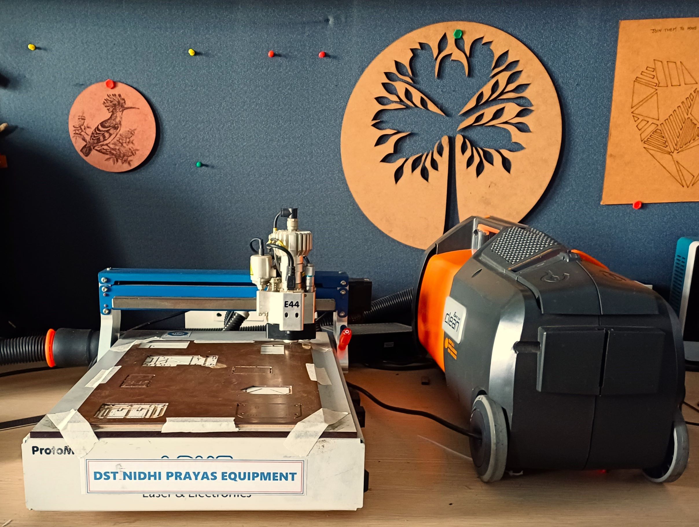
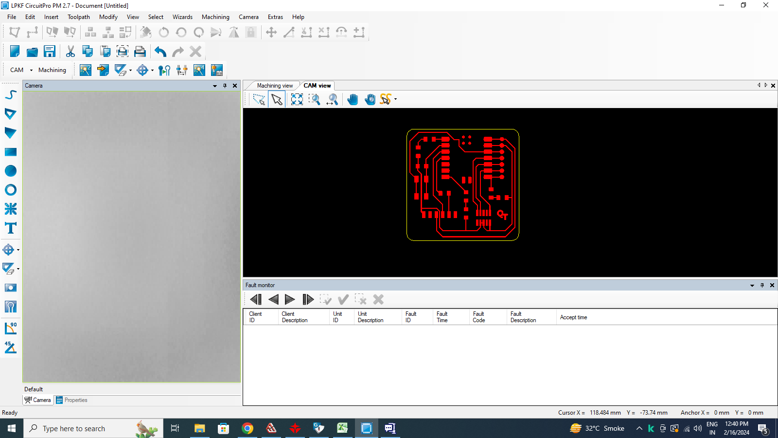
The machine we used was an LPKF Protomat E44, and it had its own software LPKF Circuit Pro.
There is a vacuum connected to the moving router of the machine which had to be switched on whenever we used the machine. The vacuum’s primary function was to suck in copper powder post the milling.

First, we understood the various tools available and which tool is used for which operation.

Then, we went on to setting up and using the software in order to get the machine started.
Connecting the software device to the machine:

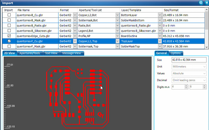
Opening the file onto the software. We downloaded the Gerber files zip of the Quentorres V1:
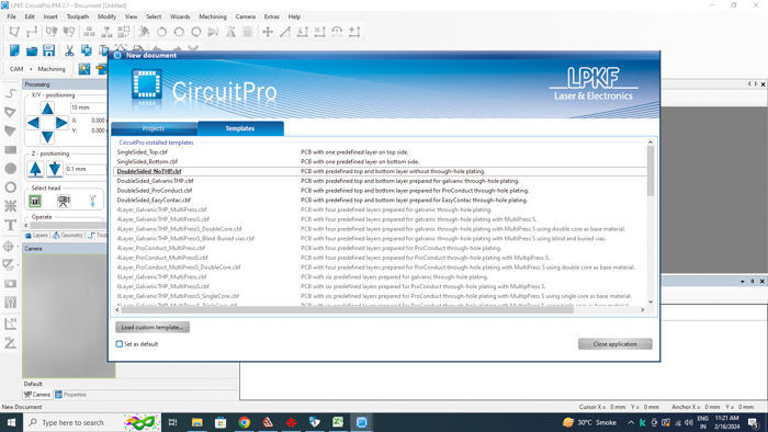
Post calibration, we loaded the file onto the software:
We assigned the layers of the different components. All of these were pre-assigned by Adrian and most could not even be edited:
Then we gave it Fudicial markings:

Fudicial markings are markings that are meant to make sure all layers and tool paths align properly. It’s like setting the origin in any other machine. And having 2 Fudicials makes it more precise. The markings prevent the layers from being offset from each other.
The markings also make sure that the milling is done in a certain section of the copper sheet and not at a random location which may have already been used.
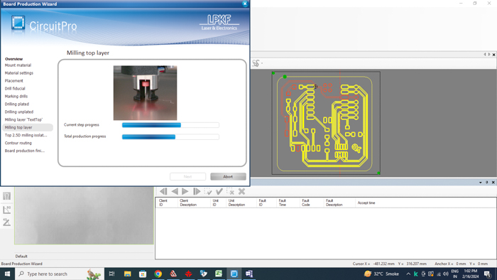
The cutting began:
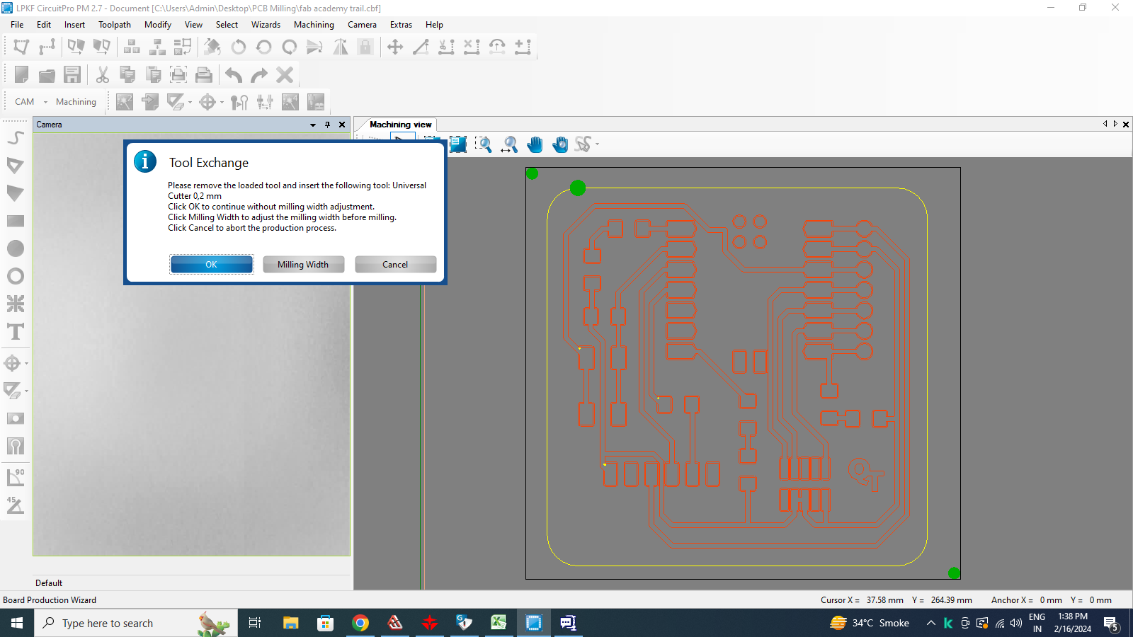
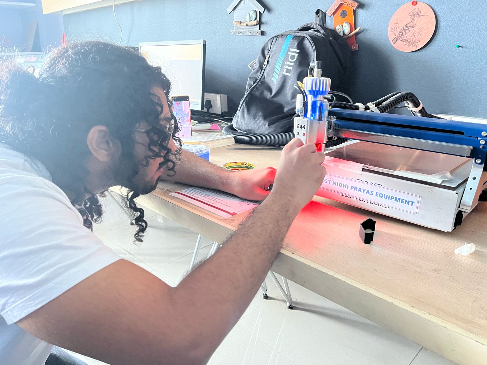
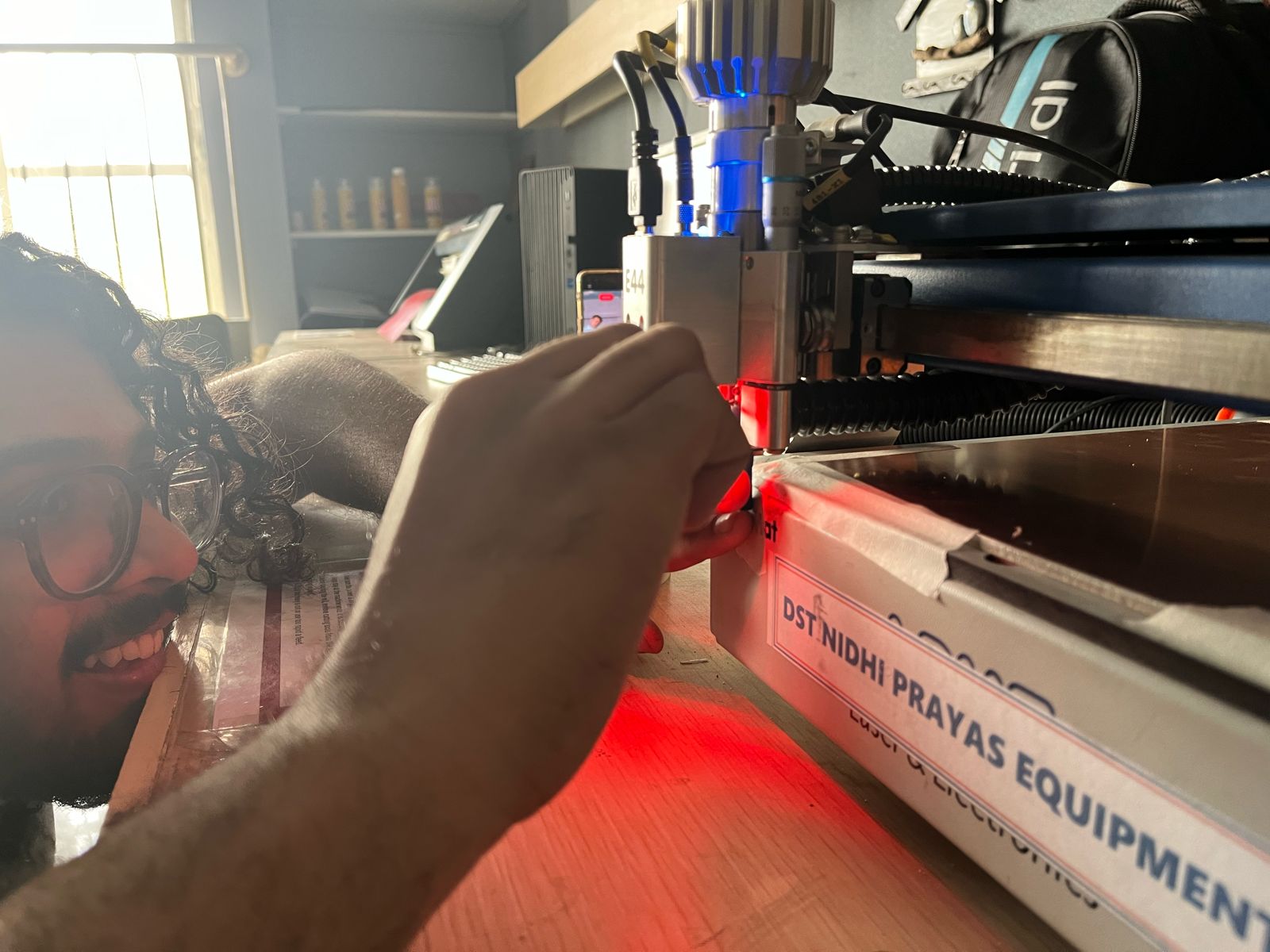
Swapping of tools:
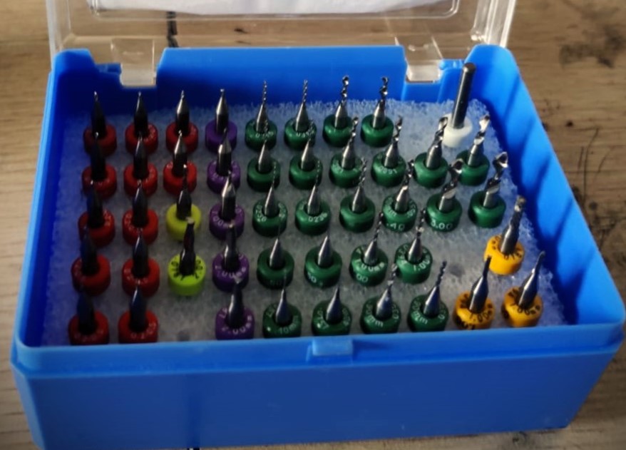
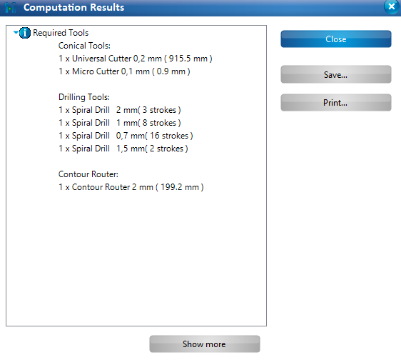
There were a LOT of different tools in the toolbox which the company had given along with the machine. Here is how that looked:
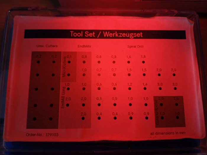
The Universal cutters had a dia of 0.2mm and were used for milling. The software prompted us to change the tool when needed and even specified which tool to use!
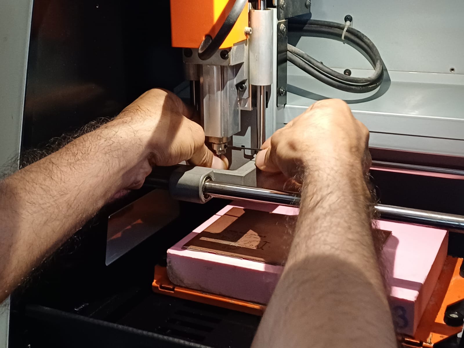
Here’s me changing the tools:

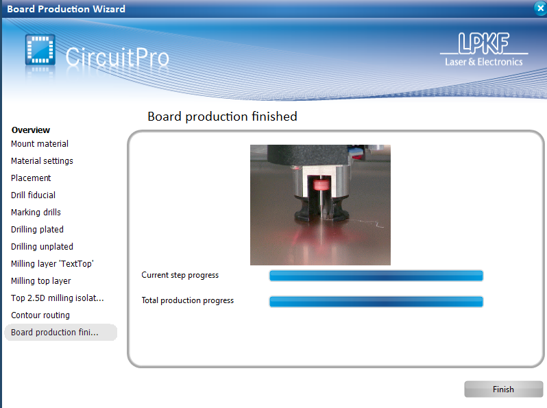
Finished according to the software:
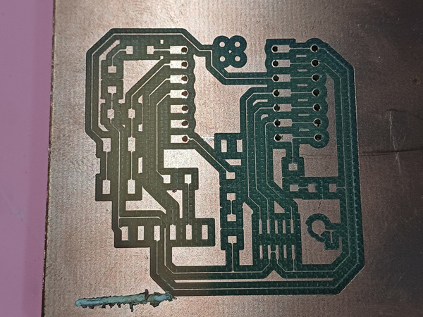
Machining the PCB- FAIL
But…
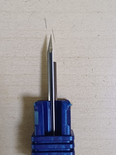
Broken tool tip
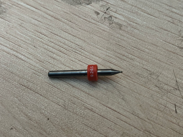
We’re not sure why this had happened. The tip of the 0.2mm Universal Cutter tool had broken off resulting in a board which was horribly burred- having cut through the copper in places where an isolation was required.

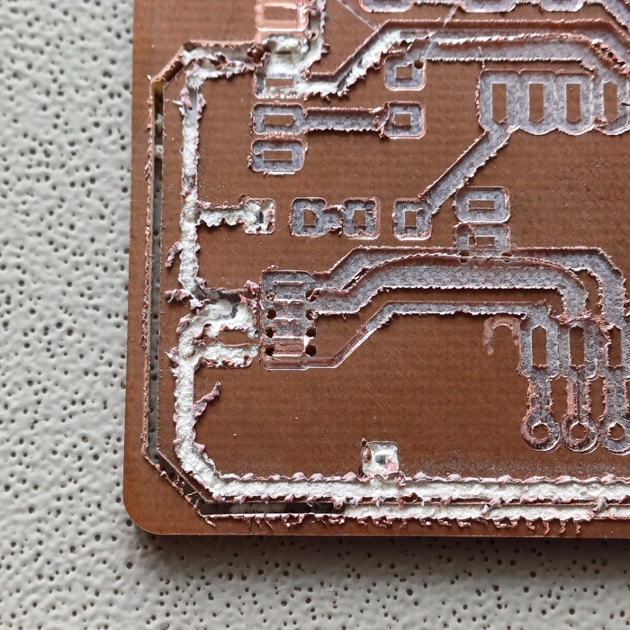

This could be because the copper sheet was a bit old and was bloating/inflated from the center, so we replaced the copper sheet along with the base sheet. And tried again.
Again, the 0.2mm univ cutter broke. The only difference between this attempt and the previous pilot attempt was the fact that we used a new copper sheet and made sure everything was perfectly flat.
Then, we tried to figure out why the machine wasn’t cutting as intended and narrowed down to two possible problems:
1. The depth and speed of the machine was incorrect and it was too fast or too deep.
2. The design file was too complicated for the Protomat.
It was unlikely that #2 was the case as pointed out during regional and global.
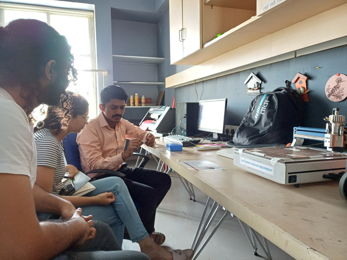
We sat down with our Mentor Jesal sir and the lab incharge, Sangram, and began trying to cut a PCB that Jesal sir had made last year in his Fab journey.
The results were the same: 0.2 mm univ cutter nearly broke. Once again, the tool had cut through the board instead of removing just the copper for the isolations.
Then we started analyzing Jesal sirs files and documentations to match the settings that he had used vs what we were using.
After this, we automated certain details (letting the software pick the tool bits on its own)
Still no luck. The outcome remained the same- the tool cut through and thankfully we aborted it before the tool broke.
It seemed like we are using the wrong tool bit to do the wrong process but the automation proved us wrong.
Then, in one final desperate attempt, we went through Pranav sirs documentation and then changed our settings to match his.
We even changed the material to pertinex from FR1.

Once we started this, another problem arose.
The Spiral drill and Univ cutter began drilling holes. However, they did the process multiple times over (4 to 5 time) without actually increasing the drilled hole size.

We decided that we needed further help and scheduled fixing this issue for a leter date.
Debugging and the Line test
Meanwhile, that week’s end, I got picked on the random generator!
Neil suggested that it is likely a bending issue or a material issue, and not a software issue. Furthermore, Leo from Waag got in touch with me and helped us understand what was going wrong. He advised that we look at the LPKF tutorial and try doing the auto-focusing via the camera on the machine in order to set the depth right.
Here’s the tutorial we looked at: https://www.youtube.com/watch?v=VVHeY1Gz_rM
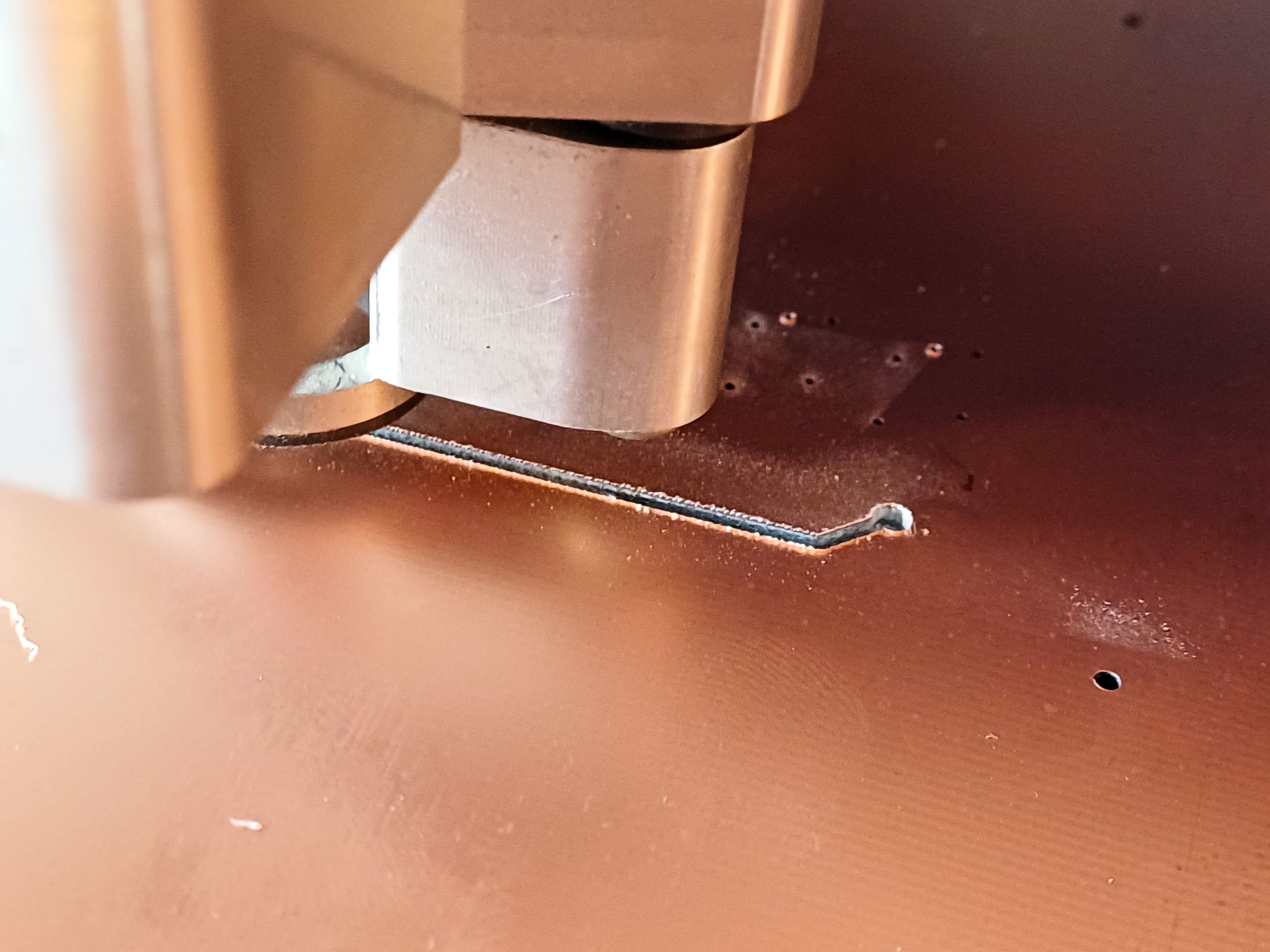
Here, we understood that the LPKF depth setting happens via the auto-refocusing. This done by the camera on the machine. When we press the button, the machine mills a line and the camera tries to gauge the line-width. Then the software gives us suggestions on how much to rotate the Z-axis screw to set the depth.
Next up, we tried doing exactly this:
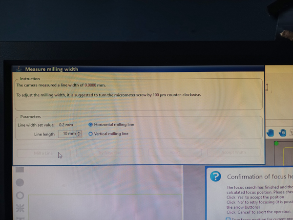
Notice the prompt suggests that the camera measured a line width of zero.

So it turned out that our camera was a bit faulty as it was not even reading the line!
This meant that it could not calibrate the required depth correctly.
We tried manually adjusting the depth (by turning the screw gauge on the side of the camera) without any calibration value and ran the line test a couple of times.

Eventually, we got a good milling depth.
Now, we just had to set the right isolation and track values to get a good PCB. Here, the tracks were reduced to oblivion.
However, we put it on hold and moved to the other machine.
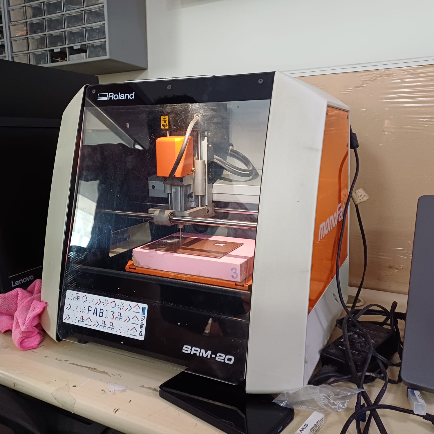
2. Enter, Roland monoFab SRM-20:
Learning operations and workflows [Done as group]
We encountered multiple problems on the LPKF and decided to start off on the our second milling machine while also trying to debug the LPKF. This secondary machine is the SRM 20.
Set-up:
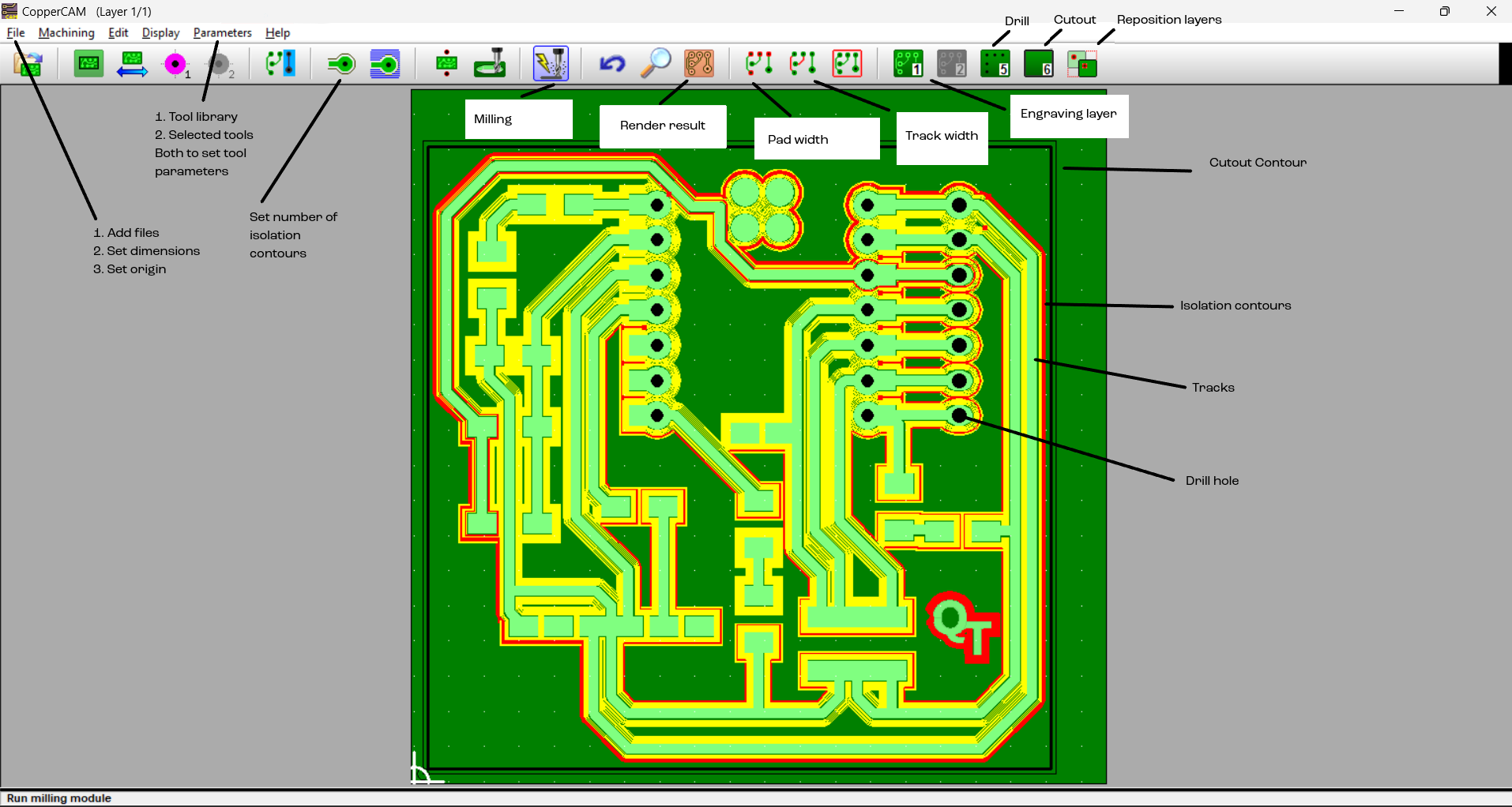
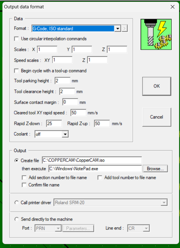
Inorder to use the SRM, you need two softwares- the Vpanel for controlling the SRM, and CopperCAM for processing your file into g-code which the machine reads.
First off, select the file type as G-code ISO standard in the file format option on the copperCAM software.

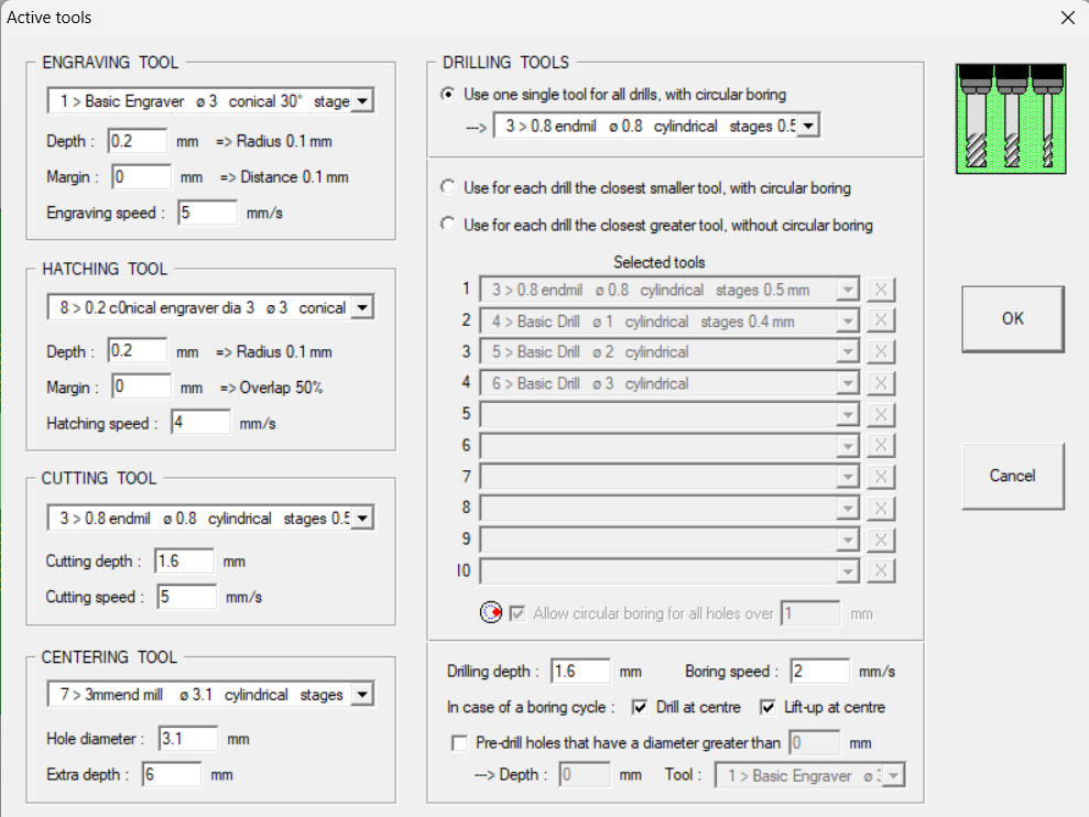
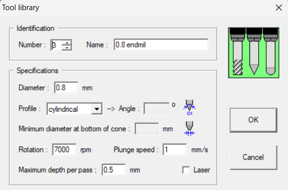
Then, set your tool parameters. We used a 0.2 mm V-bit for milling and a 0.8 mm Endmill for cutting and Drilling:

Selected Tools:
Tool Library:

Then, load the file into the system:
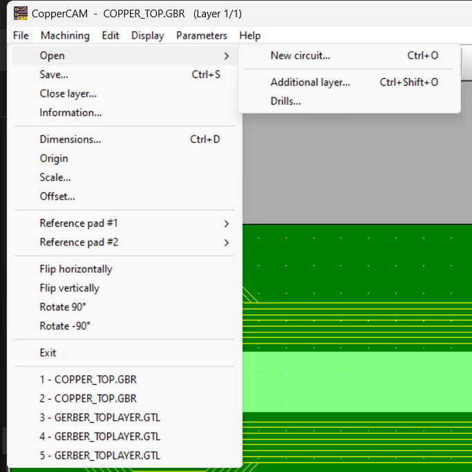
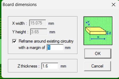
Keep in mind to Reset Origin to 0, 0 everytime you do something. Also, Dimensions should be set as 1 around the board. Both under the FILE option.

Tracks and Pads go under the Engraving layer (which is Layer 1 to 4)
Drill Files go in layer 5
Cutting contours go in layer 6 (If by chance it goes in engraving layer, you can try right-clicking on the contour and selecting the option Set as Contour path)
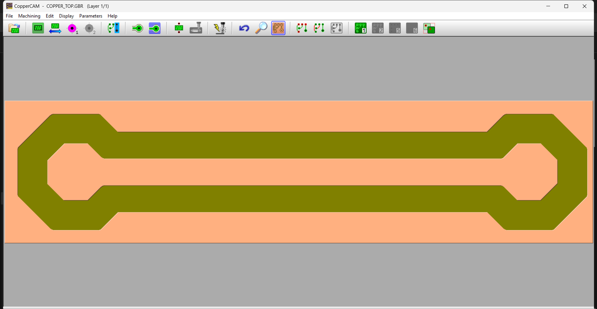
Next, click on the isolations tool:

And click OK and go to Render PCB.
Click on Mill:
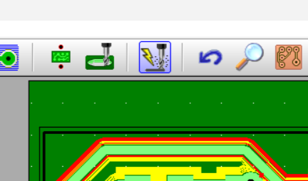
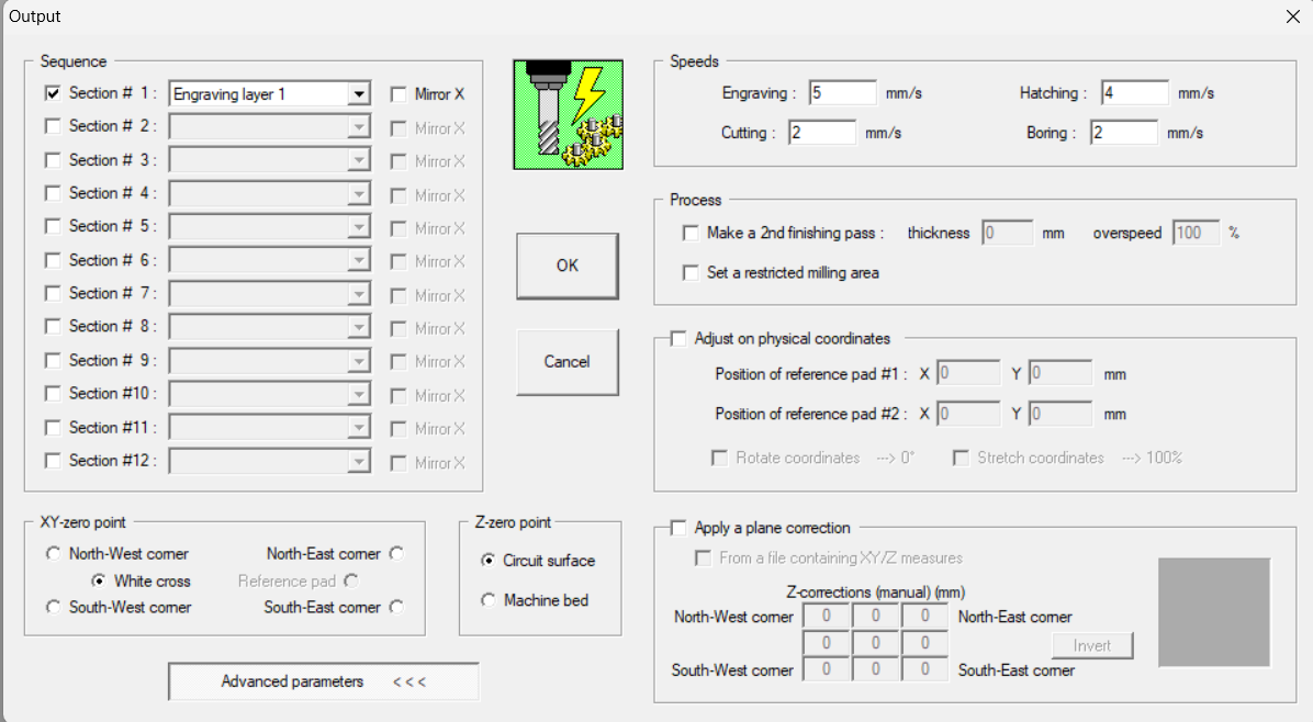
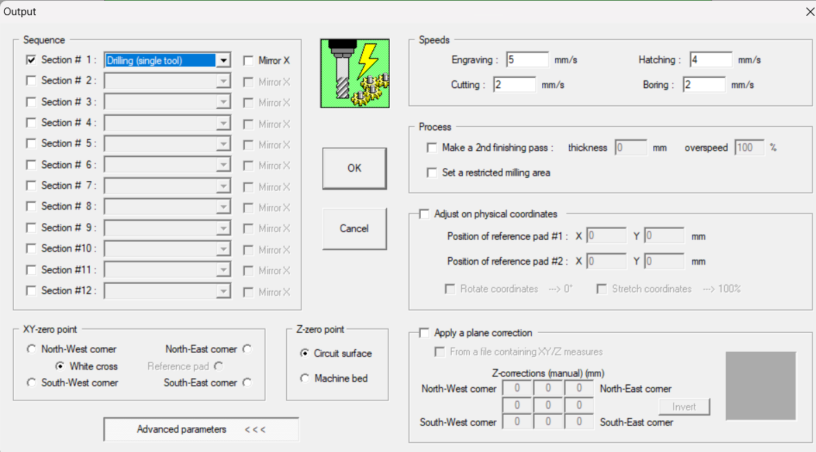
Select the operation you want to perform:
Engraving
Drilling
Vpanel interface:
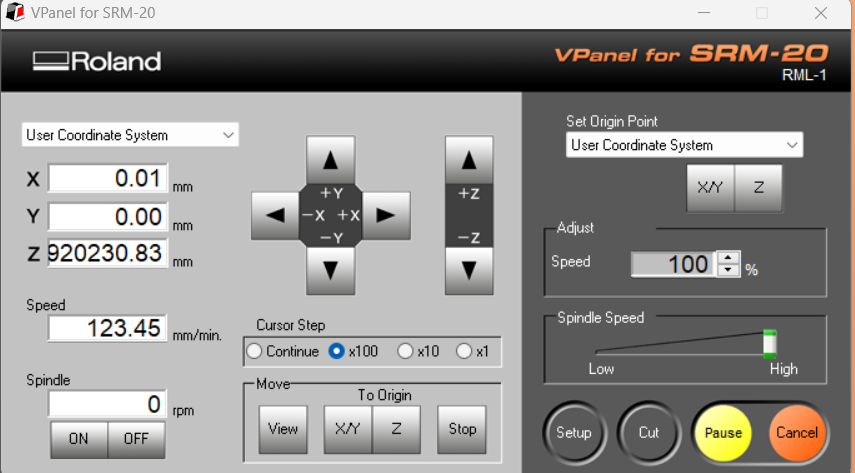
This is what will connect you to the machine. You can use it to pause or even cancel jobs.
Here, if you click on the XY/Z buttons on the top right, it will set the origin.
You can set XY origin anywhere depending on where the copper plate is. Remember, you also need to set the origin on coppercam as 0,0 and choose the option of south-west corner or white cross in the settings.
Z-axis is set by loosening the tool (using allen key) and allowing it to drop on the copper sheet. Alternateively, you can keep the tool tightened and move a sheet of printing paper on the copper plate. Start lowering the Z till you achieve friction between your moving paper and the tool tip.
The “To Origin” button just takes your tool to where the origin is currently set.
Tool-changing:
0.2 mm V-bit:
Tools are changed by using allen key on the colet:
We used Double sided tape to stick the copper plate to the pink base. Make sure you put the tape evenly so that the plate is balanced perfectly. While removing the plate/milled PCB, take extreme care as the milled PCB can break (happened to me in my Final Project). Try twisting the copperplate or gently removing the tape so that you don’t end up bending the plate either.
Trials and errors to set up the correct setting
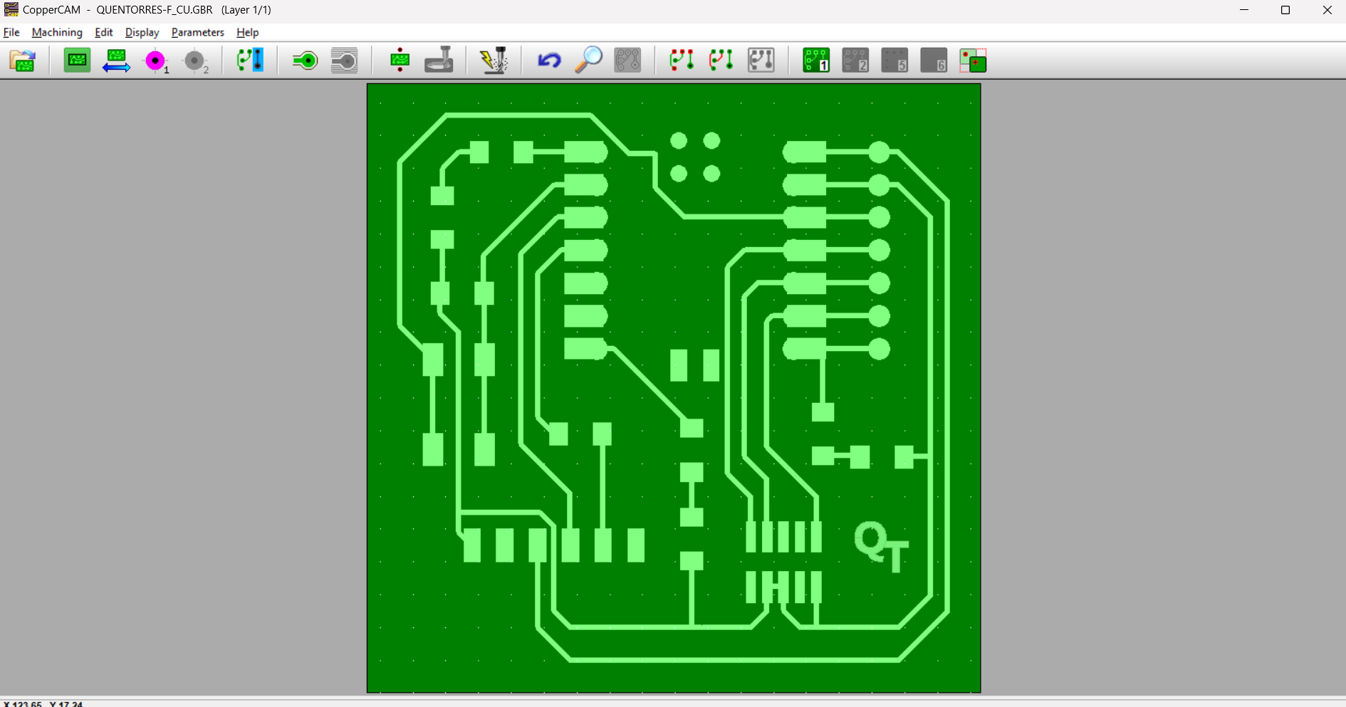
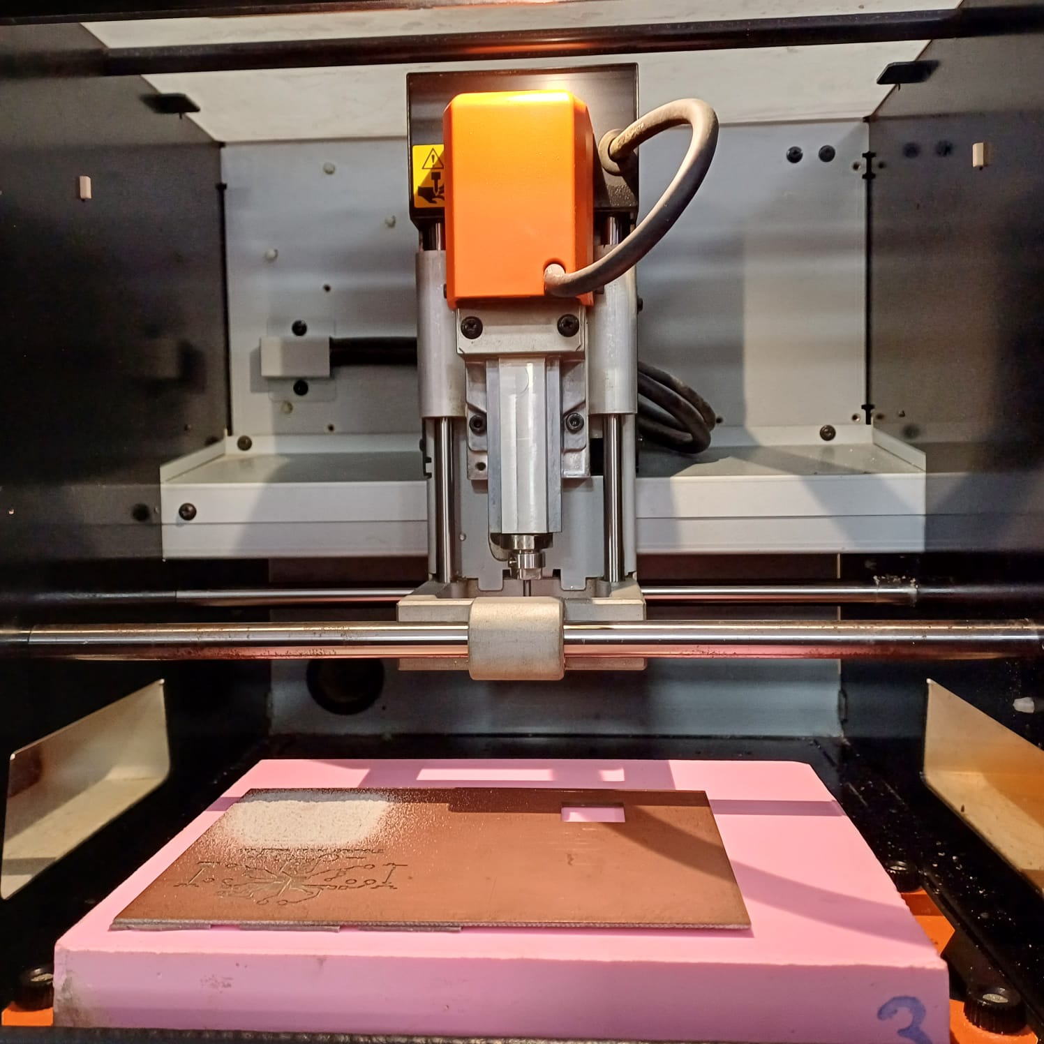
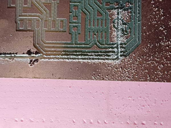
We started out by milling QTs.
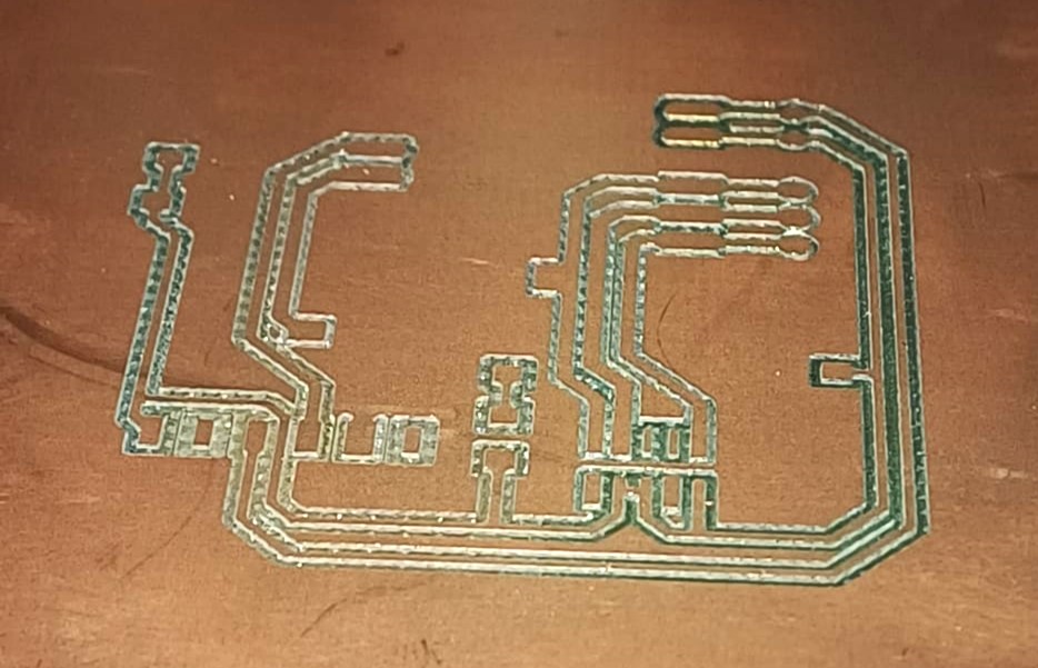
The first two were heavily burred and the connections were too narrow:
z-axis at zero (touching the copper plate)

z-axis at +0.2 mm (slightly above the plate)
Comparison
In our subsequent attempt to mill another QT, we changed the number of contour isolations to 4 (from 2) but challenges persisted. Despite setting the number of contours as 4, the isolations turned out overly broad, while the tracks appeared really thin. Upon giving the cutting command, the machine inexplicably reset its origin and proceeded to cut through the milled tracks.
So then we decided to use a smaller “Trial PCB” to test milling settings.
We continued to mill a few more tests with varying contour counts and depth:
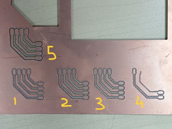
1st trial..z origin + 0.1 mm, 2 contours
2nd trial.. 4 contours, 80% speed on Vpanel
3rd trial contour number change to 4, speed to 2
4th trial speed change to 10.
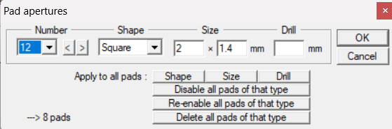
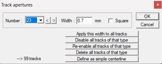
5th trial..track width 1mm, pad width..2mm. 6 contours
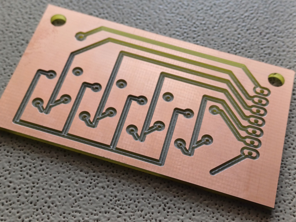
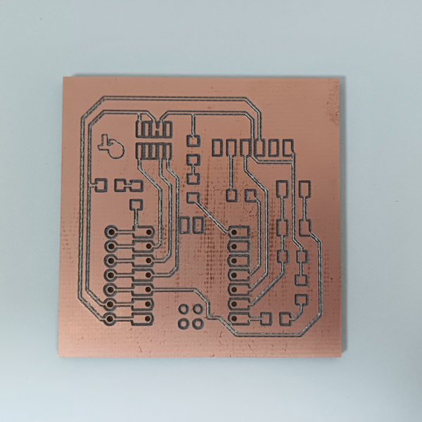
Finally, we increased the track width and isolation widths manually and voila! This worked:

6th trial..track width 1 mm, pad width 2mm, 10 contours..10x above z axis

0.2 mm depth. 9 contours. 0.7mm track width, 1.7mm pad width
0.5 mm depth. 9 contours. 0.7mm track width, 1.7mm pad width
Final thoughts on tool stats:
1. An engraving depth of 0.1 to 0.2 mm is fine.
2. Contour lines- the more the merrier, and easier soldering. 8 to 10 is good.
3. On copperCAM, it helps to manually change track and pad widths
- Track width: 0.7 to 1 mm is good
- Pad width: 1.7 to 2 mm is good
4. Z-axis adjustment really depends, at times it works well, at times it doesn’t. Either way, make sure to deburr using a small piece of sand paper. It will prevent unnecessary current leaks caused by contacting burrs.
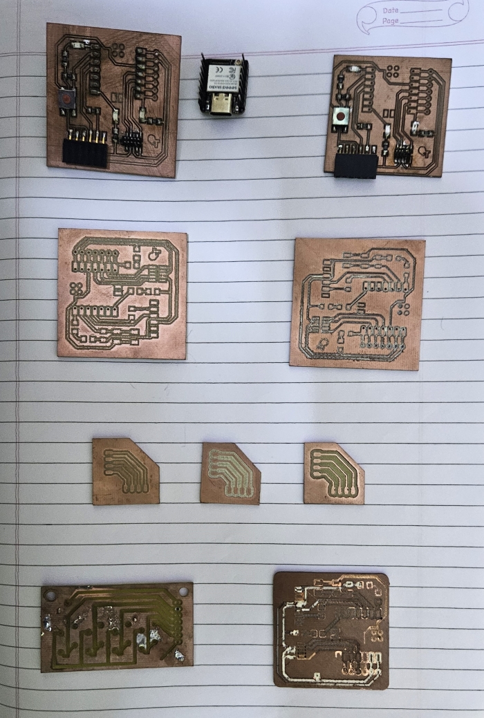
Here’s my final page of PCBs trials for week4:
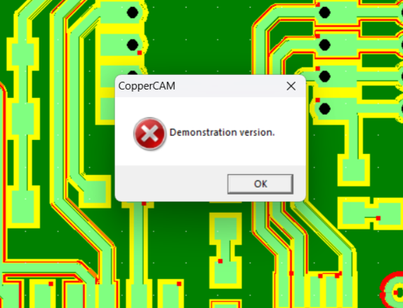
At some point, I got confident with the settings and decided to mill a QT. I fired up my personal laptop and downloaded copperCAM. I installed the drivers and ran the driver suited to my windows 10. CopperCAM was up and running! I began milling. I got really excited as it was giving a good result after all the hours spent in getting good settings. As my excitement peaked, the machine suddenly stopped!
It stopped at the halfway point and gave me this error T_T:
From then on, I stuck to the PC provided by the Lab as that had the licensed version. #Learningthehardway.
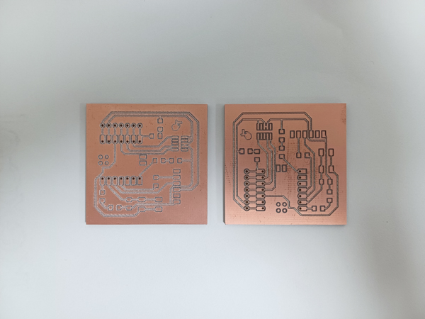
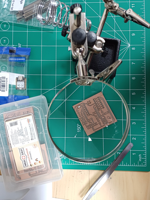
Final milling of QT- SUCCESS!

3. Welcome to the Solder Side- Soldering the QT:
First I used a multimeter to check connectivity betwen the milled tracks.
Here, you use the probes of the multimeter, set it to connectivity, and connect the probes to the PCB pads between which a track runs.
At every stage of soldering, make sure to check the connectivity.
Trials and errors
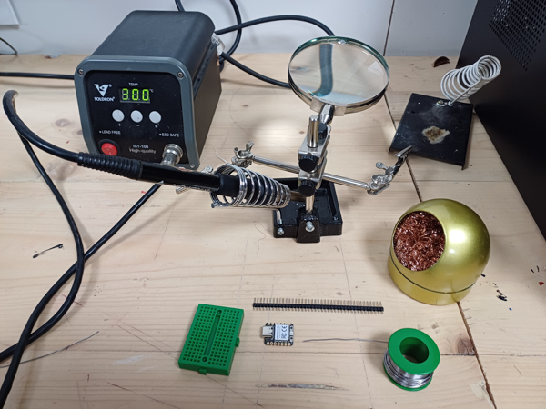
Soldering station:
Soldering an SMD LED..they are so TINY!!!!

Soldering other components:
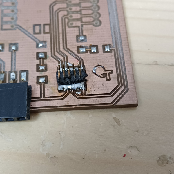
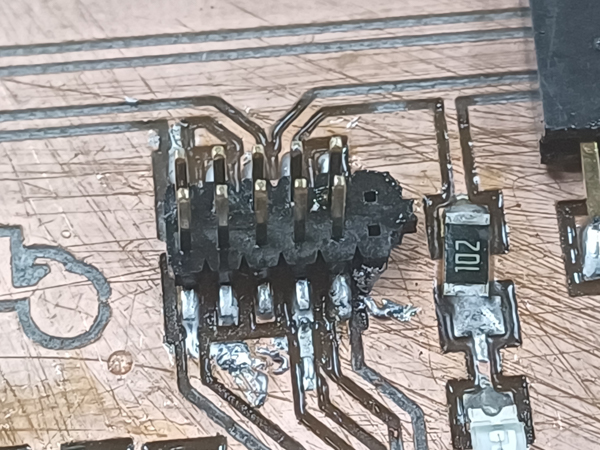
This set of pins failed as I thought I would copper them all in solder and them desolder them using the copper wick or the vacuum pump.


As seen above, it’s terribly done even after usign desoldering pump.
The pad is damaged, and the solder is overflowed.
Plus, the other components were poorly done too!

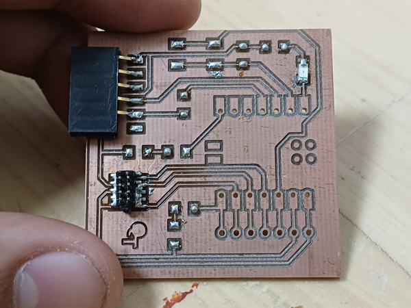
Soldering SUCCESS!
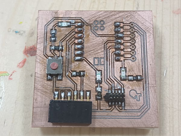
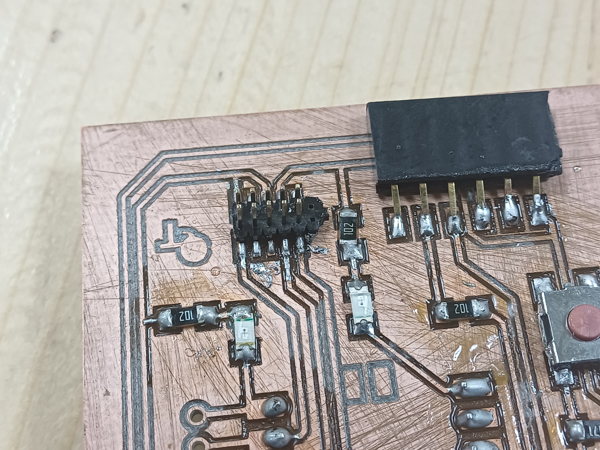
Finally, I restarted on another QT and the results were great this time! Using flux really helped as it allowed the solder to stay on the copper pad.
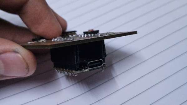
We had the Xiao ESP32 S3 board at the lab along with the RP2040. By the time I finally got a good QT, we were nearing the Networking week. Hence, I went ahead with the Xiao ESP32 S3. I wanted to make it modular in case I wanted to connect the RP2040 to the QT at any point. So, I soldered female header pins on the back via the drill holes.
I also soldered male header pins on the Xiao board.


4. Blink-Bop-Beep! Testing the QT:
To understand how the Xiao RP2040 can be set up and what libraries are needed on the Arduino IDE, please refer to my Week 6 Documentation. You can refer to the Quentorres documentation as it talks about the same as well.
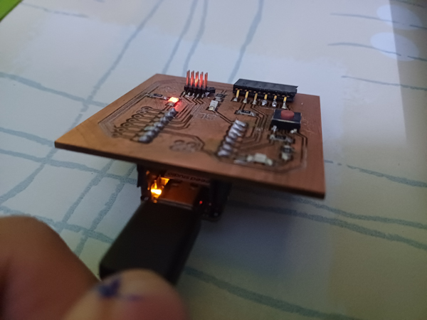
Once the set up is complete, the board is ready to take up the code!
Blink code:
On the Xiao board LED-
On the QT-

Button press triggering an LED:
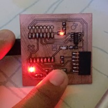
One button, Two LEDs-
One button, one LED-
5. Sending a PCB design to a board house
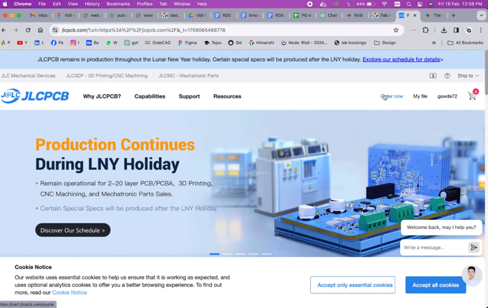
We availed services of the board house JLCPCB to place an order of the QT v1 board. We did this with the help of Pranav sir.
The landing page greeted us with various features of the board house. We logged in and clicked on “Order now”.
Here, we chose from the 4 different types of outcomes we desired and went ahead with the standard PCB.
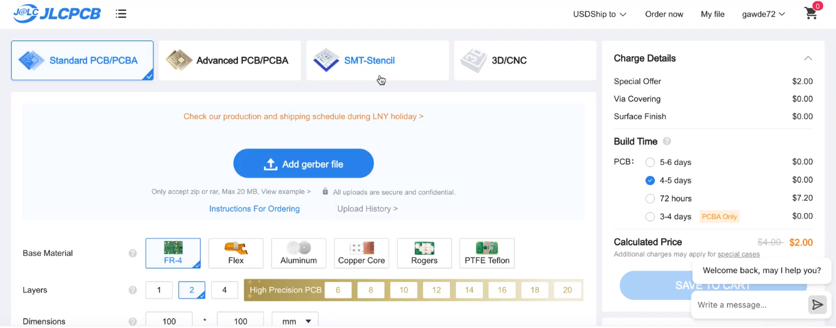
We added The gerber zip files to Adrian’s QT v1. Once that happened, we could see the board layout in a small box on the page.
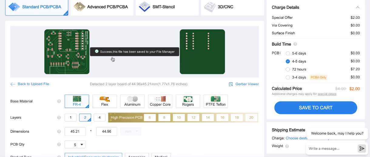
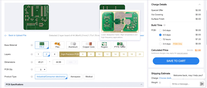
Something to note here is the unique User Interface, which allows the user to know about every technical term mentioned. For the base material, simply hovering over showed you how the base material looked and what its features were.
We chose the FR4 base and set the order quanitity to its minimum, i.e, 5.
We went ahead and chose black as the color along with a white silk screen. Immediately, the diagram above reflected our color choices.
We stuck to the default surface finish of HASL(with lead).
Another UI point to mention here is the tiny ‘?’ symbols near the criteria name. This helps you understand the criteria and its contents better.

The ‘?’ about Vias:
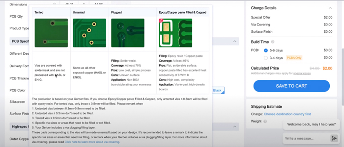
We finally gave in the final bits of detail:
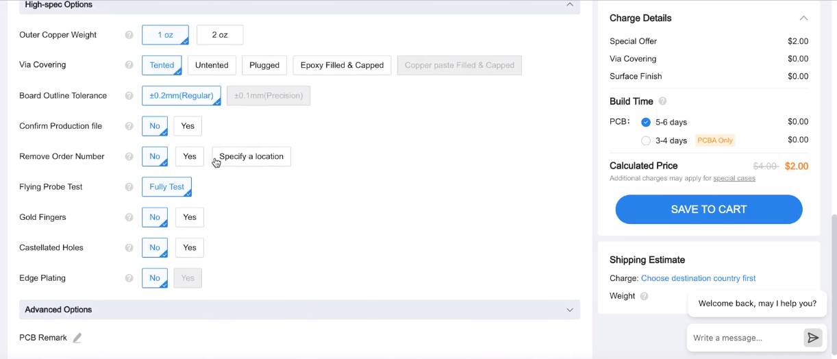

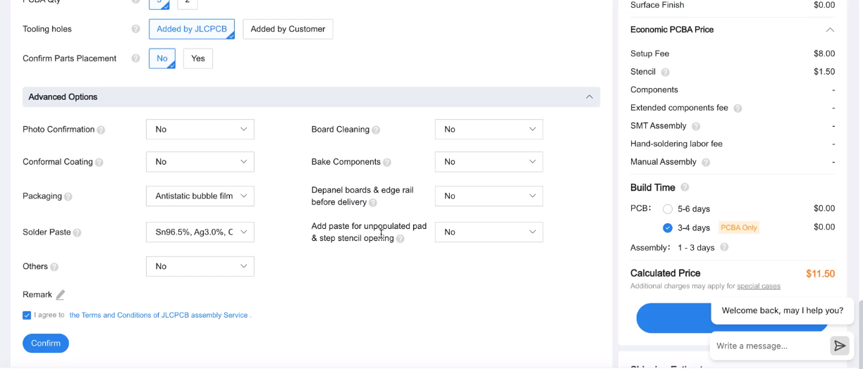
Proceeded to checkout. The PCB is in the cart!
Here, we learnt that JLCPCB has a unique feature where you can lock components into your cart without paying for it immediately. This allows you to block items for you before they run out of stock, and you can pay and have them delivered at your own convenience!

And finally, feeding in the address of delivery:

We also tried reaching out to local Indian vendors who manufacture PCBs. You can find the documentation of that on my classmate Himanshi’s page
Class Summary and Lecture Notes:


Running notes during the class:
class 4 notes:
Megan - glass engraving..wet napkin and rotate with hand
“we use wet napkins sometimes as well to engrave glass. It is to prevent roughness. I believe it is because of less heat”
Fire safety etc included..good
Sandblasting..vinyl cutting
Video convert to mp4 and compress. Dont upload on youtube. CAD week in the website of Fab… mp4 to html embed
Dont use gifs..loop mp4
Student Haro- Bamboo Charkha: portable, cotton spinning wheel, made of bamboo
You can also have a look at Sara Diaz’s HILO spinning machine
More textile examples
Shemakes project on wool in Europe
smart citizin
FMCU:
https://pub.fabcloud.io/project/bootcamp-2023/fmcu/
https://fmcu.beachlab.org/
Christo - wrapping giant things..projects
Barcelona - riichiro yaamamoto something MUST LOOK PROJECT
Amanda Ghassae
Origami figures
Cable robots, choreographing
Cable bending robot dance
Cheap LiDARs library
Dance project
Camera module
Image classification demo made with XIAO
tinyML Workshop done in Bhutan
Rodrigo diaz - light saber
Loes project
Heres a pill dispenser
Curio 2, cutting machine
Etching - 1 sq m consumes 1 cubic meter of water or so?
PCB- FR4 toxic..glass reinforced so not good
Mods
Stick to quentorres board
Here is all the XIAO Board list