7. Computer Controlled Machining
This week, we learnt how to use the CnC miling machine at our. It is the Numac Hitech machine with a bed size of 8 by 4 feet.
Group work
Safety instructions for using the CNC router:
- Safety goggles should be worn at all times in operational zones.
- Wear a mask when excessive dust or hazardous fumes are present.
- Avoid wearing rings and jewelry near moving machine parts.
- Tie back or secure long hair to prevent entanglement.
- Wear close-fitting protective clothing or a workshop apron.
- Wear sturdy footwear with reinforced uppers.
- Familiarize yourself with the ON/OFF and emergency stop controls.
- Ensure the waste collector shroud and coolant system are properly adjusted for optimal performance.
Toolpath Making on Fusion 360
We used Fusion 360 for making the Toolpath. The file format was .mmg which would require you to download an extension (I’ll elaborate further on).
So, first steps first, you create your design file. This is done as an outline geometry. Then, you create a geometry for the bed and nest the design paths in it. This is done so that you don’t have to set a new origin every time.
This is how my file looked like:

Setup:
STEP 1: Start setup
Start by going on to Manufacture panel on Fusion 360 (Top left dropdown).
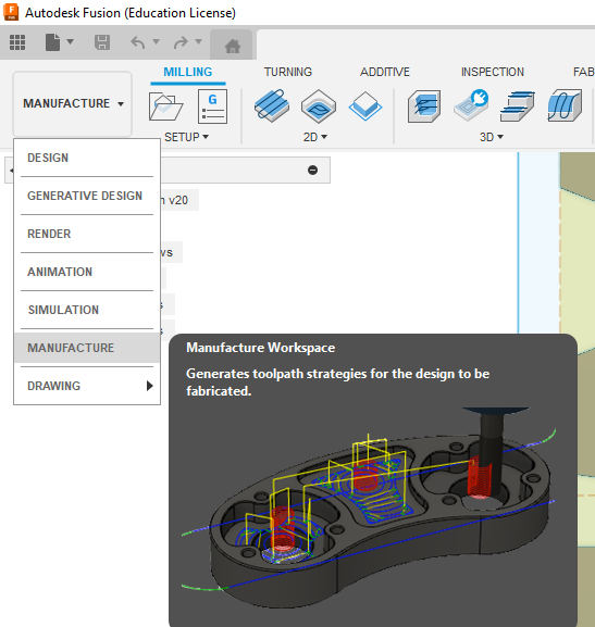
Then click on, Create “New Setup”.

STEP 2: Select Machine
Once you do this, a dialogue box will open up asking to select your machine.
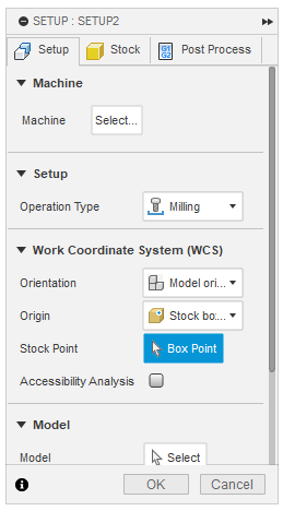
If you know which machine you are using, go ahead with that. Else you can go to https://cam.autodesk.com/machineslist and download the required machine library.
We used the Generic 3-axis router where XY is on Table and Z is on Head.

Next, select the Models you will be machining. Set operation type depending on what you are doing. Finally select the origin of the toolpath.
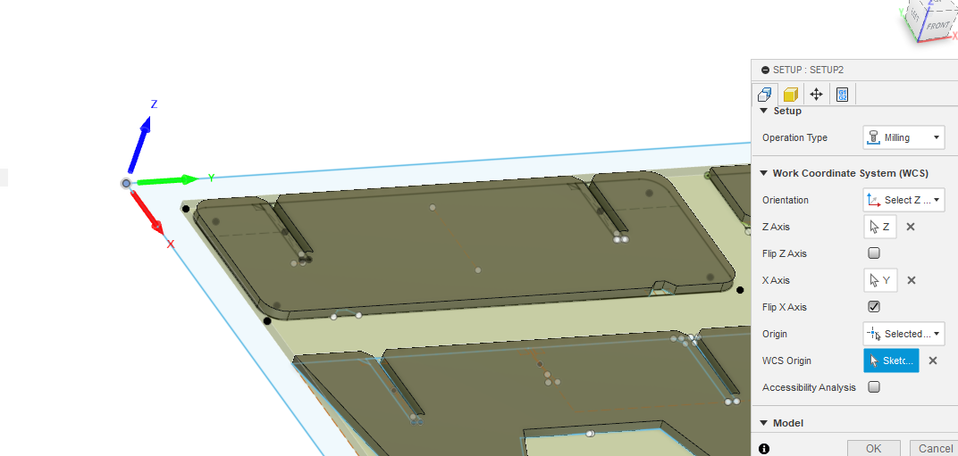
STEP 3: Origin and Orientation
Make sure your orientation aligns with the machine’s orientation and the Origin aligns with the corner of the stock geometry. This way you won’t have to keep setting the orientation for every toolpath you create.
STEP 4: Fixtures
Fixtures are done manually so there is no need to change anything in the fixture setup.
STEP 5: Stock box
Stock settings are usually used if you have a material which is uneven/irregularity in surface. The Standard deviation = stock offset.
Stock Offset is generally recommended at 1 mm.
Don’t input any post processor during Set-up.
Setup is done
Create 2D contour:

Tool considerations:
- First off, we check the material thickness. If the material is 5 mm thick, then the tool we use is 30mm long (+ safety), so around 35-40mm.
- When doing 2d contouring, we use a flatmill tool.
- Diameter and Shaft diameter: Shaft is the part without flute. The shaft goes inside the machine.
- Flute length can be 20mm.
- Shoulder: It is the height of the flute till its end. Usually around 25mm.
- Length below the tool holder is 30mm.
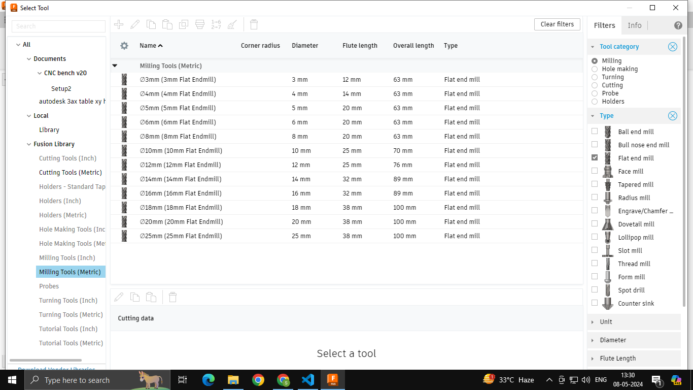
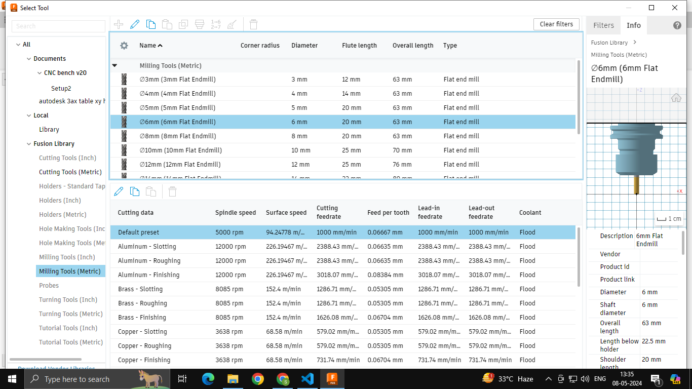
Tool list
We used the 6mm flat endmill with a flute length of 20 mm and an overall length of 63 mm.
Tool selection
We disabled the “Coolant” setting as it is not present in our machine.
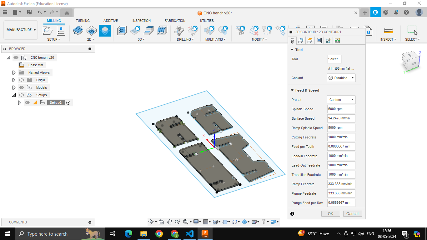
Original Feedrate and Spindle Speed as per tool default
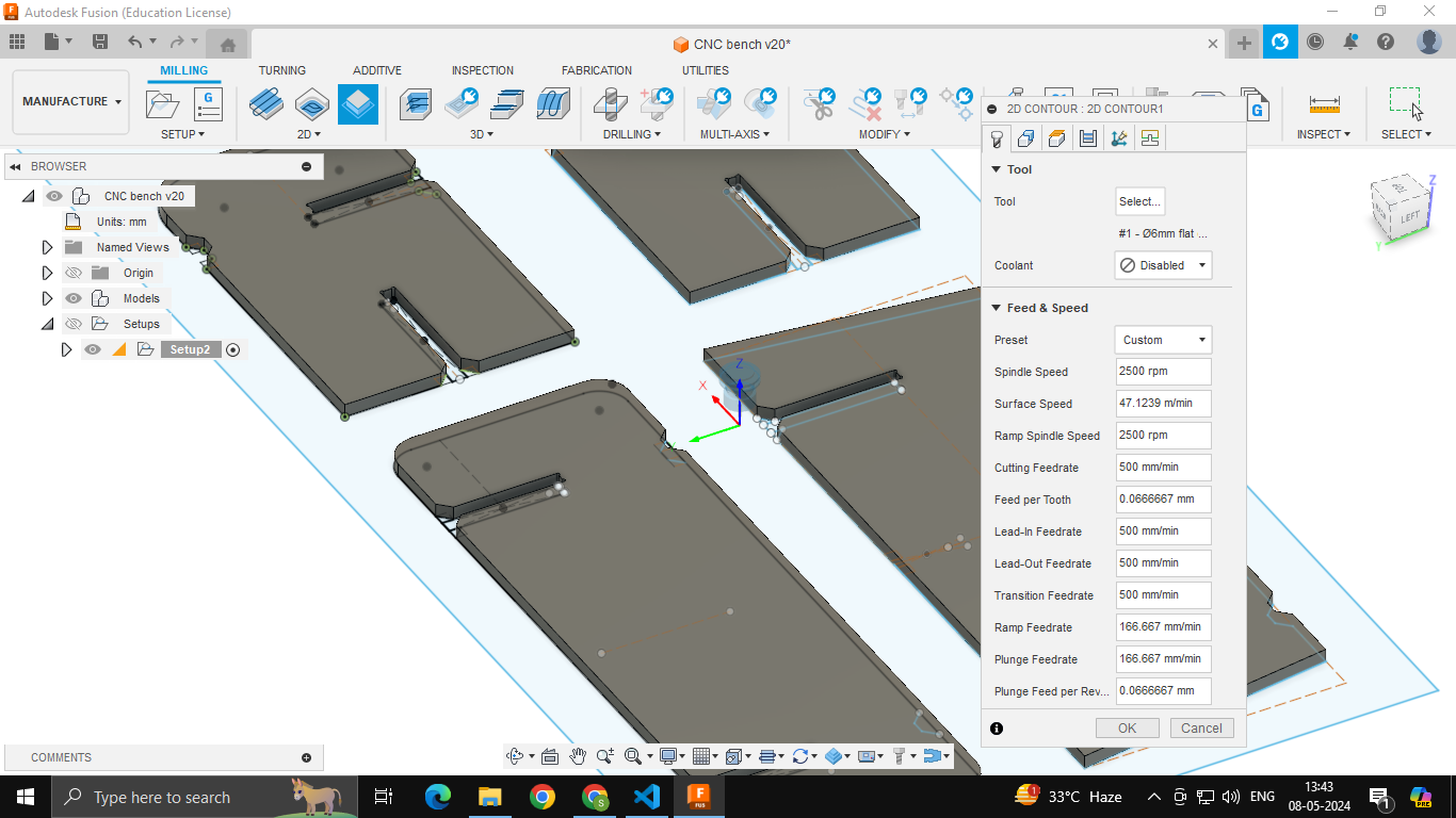
Feedrate and Spindle Speed cut to half for Trials
Cutting data:
- Each tool (based on the material thickness) has a default rate for feed and speed.
- 12,000 rpm is the workspeed used for 6mm for plywood or mdf. For trial cuts, start with 0.5 of this.
- Cutting feedrate is generally between 500 to 1000.
- Start out at 0.5 times of spindle speed and 500 as feedrate for trial. Then once you see that it is cutting fine, increase the values.
- Dont let plunge feedrate exceed 400. Otherwise it will burn the material.
- Dont add stepdown and step over in software.
Choosing Geometry:
Under the Geometry section, select the path outline you want to route and disable everything else.
You can create separate tool paths or create a single toolpath with routes inside.
It is recommended to divide into multiple toolpaths beacuse for example, if your fourth route fails, the machining will restart from #1 when you use a single toolpath with multiple routes.

Heights:
Change Bottom Height to Model Bottom when you are machining a Flat part.

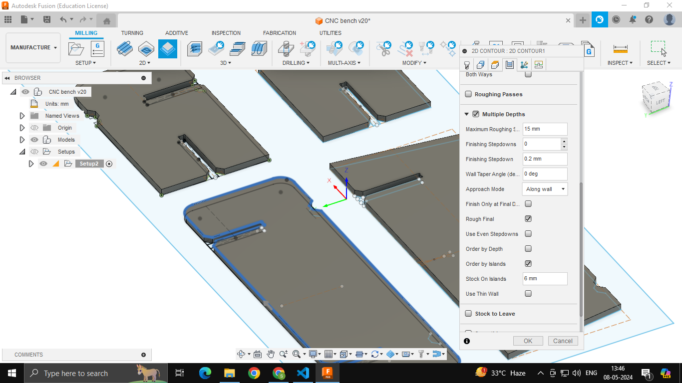
Passes:
Under Passes, enable Multiple Depths.

Set Max Roughing Stepdown as 3 mm if you are using Plywood.
Finishing stepdown (if it should go further down after finishing the cut) is 1mm.
Enabling the “Order by Island” setting eats away a bit of material around your model. If you have a closely nested model, then you can leave it unticked.
Linking:
Dont change anything in linking. Keep leads and transitions off.

Now, your toolpath is ready!
In order to route multiple models in the same process, i.e., 2D routing, you can simply duplicate the Toolpath and change the chosen geometry.
Post the Toolpath:
In order to post the toolpath as a file that the machien can use, do this:
- Select all Toolpaths you want to route
- Right click and select Post Process
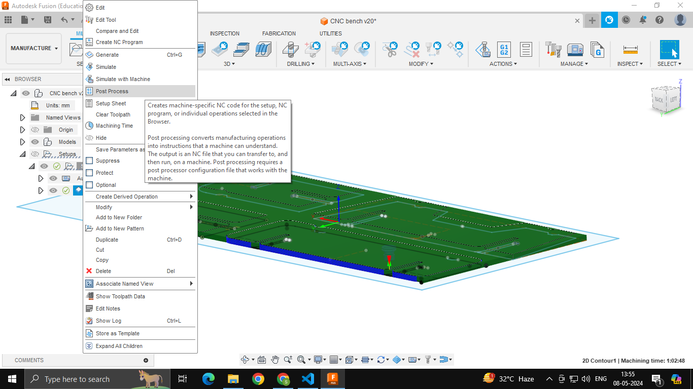
- Select Post as “Generic Chinese Router, Ledio”
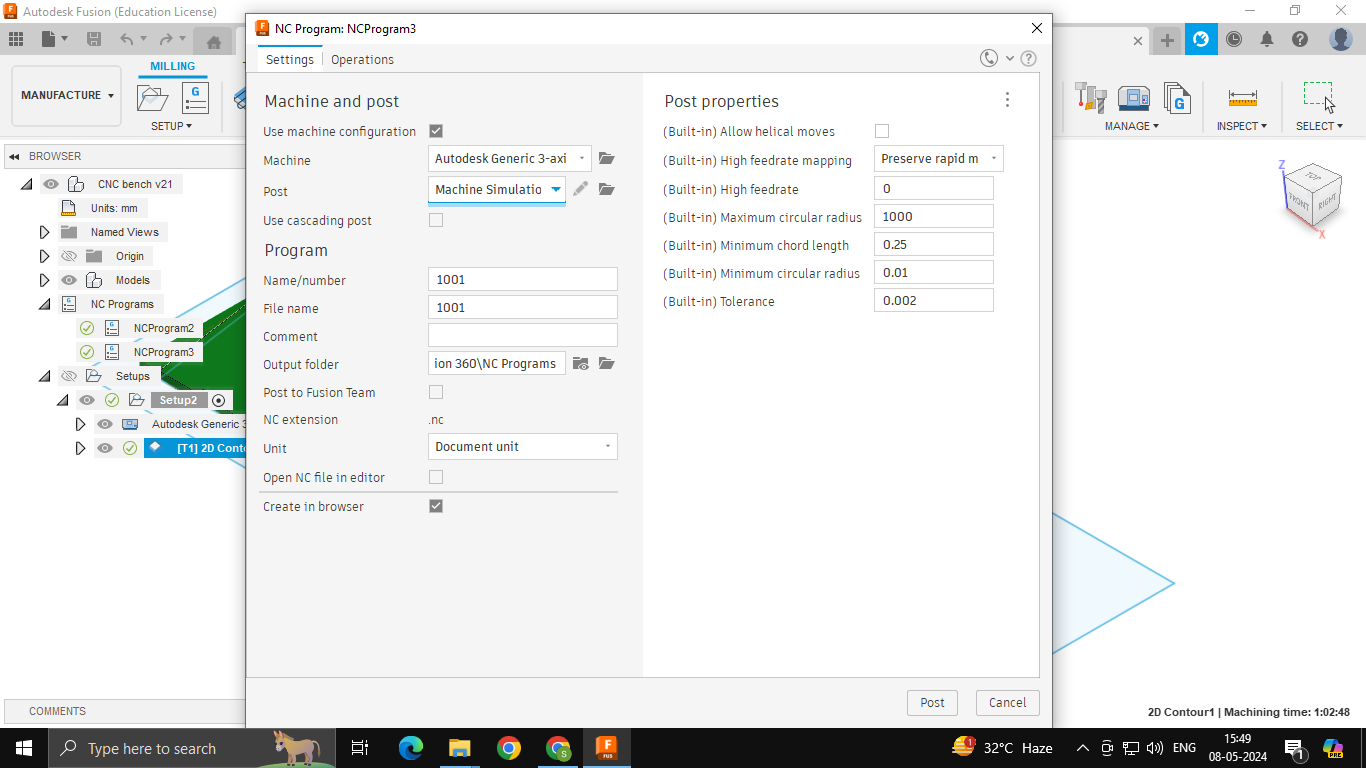


Our machine only reads MMG files, which requires a Ledio Post Processor. In order, to get the Generic Chinese Router under your Post Libraries, you will have to download the extension, find the Fusion root folder in your system, and move the downloaded extension into the library root folder.
Quick tip here: Use the search bar to find the .cps files (which are in the Post library). You will find a list of existing Post Processors. Now open file location and paste the Ledio cps file into the folder.
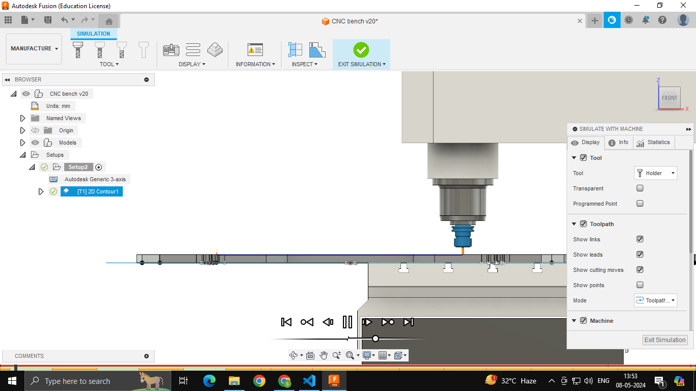
Simulating Toolpath:
In Fusion itself, you can make use of the “Simulate with Machine” feature to preview the routing.
Simply right-click the Toolpath and select the Simulate with Machine feature.

Here you can enable/disable different modes for viewing.
Machining
Trial Cut
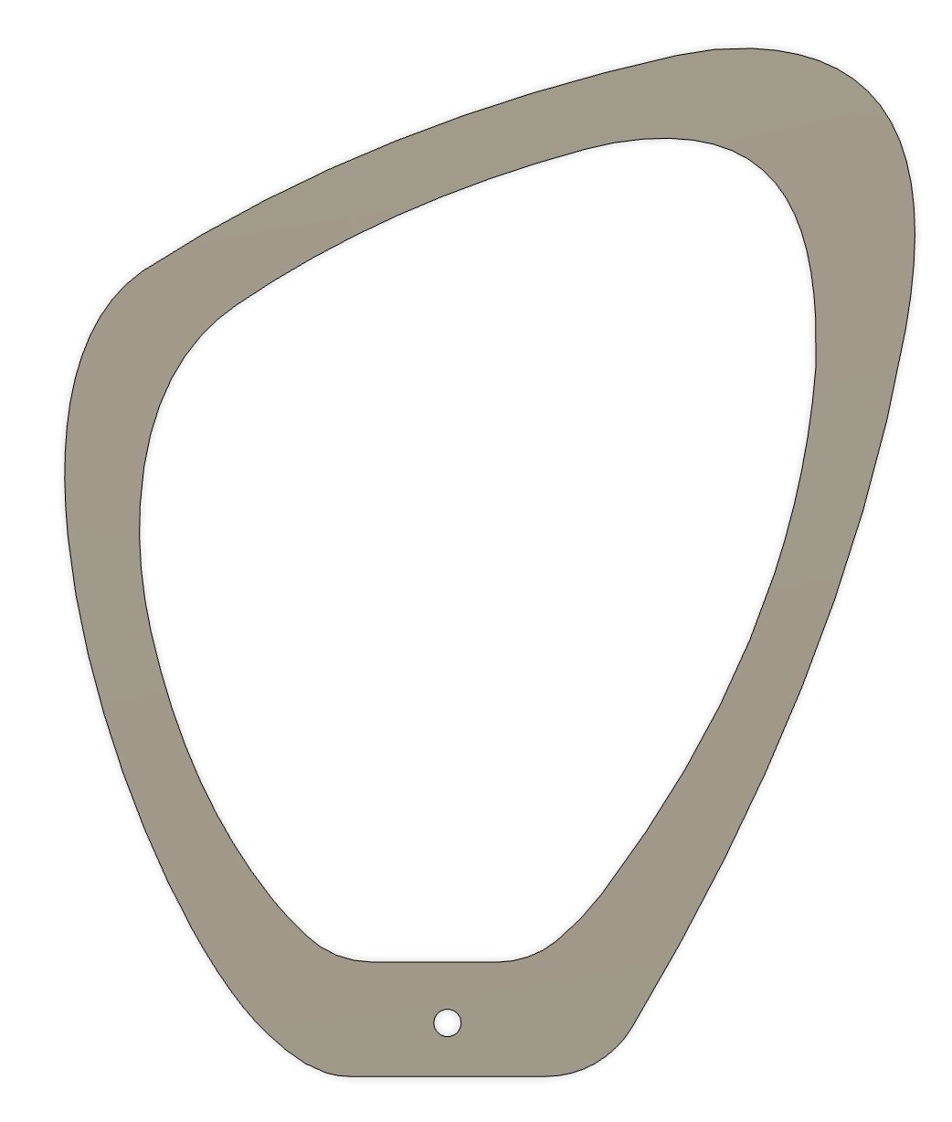
During our group demo session, we tried the machining a test file. This model was from one of Himanshi’s college projects. It was essentially a ring with 3 paths:
- Outer radius of the ring
- Inner radius of the ring
- Small hole in the body of the ring
It looked like this:
The inner ring and the hole worked well in the simulation so we went ahead and did an air trial. That can be seen here:
The Inner ring was fine in the air pass as well so we went ahead and cut the inner ring out.
Securing the Part to the bed:
Here, for the trial ring, we used a method called “Onion-skinning” which is leaving a very thin layer of ply at the base of the cut part so that it is still attached to the stock. This prevents the part from moving while nearing the final cut passes. If the part is not secured when being cut, it can move due to the vibrations of the machine and cause damage to the tool or the part, or even break off the tool and damaging the surroudings.
Other methods of securing the part include using tabs, which are supposed to be given in the design file itself. Tabs are small bits of the stock that are uncut. Tabs connect the part to the rest of the stock and prevent it from moving around.
Another method is using nails. You can hammer a nail down the stock and into the sacrifical layer so that the part is secured when cut.
It is important to use multiple tabs or nails so that the part is firmly secured. Even a little bit of movement can cause the tool to break off and fly off at you like a bullet.
The outer ring was also alright in the simulation, but when it came to air trial, the movement of the router was VERY stuttered and jittery. We couldn’t understand why that was happening and our instructor recommended that we do not make the cut as it could damage the tool as well as the ply.
We put the cutting on hold for that day.
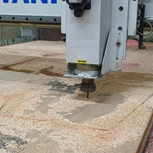
Machining process

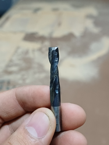
This is the tool we used. In order to insert/extract the tool, you must use 2 spanners and turn the two nuts in the opposite direction.

Once you have your stock set up on the bed, make sure to clamp them in place.
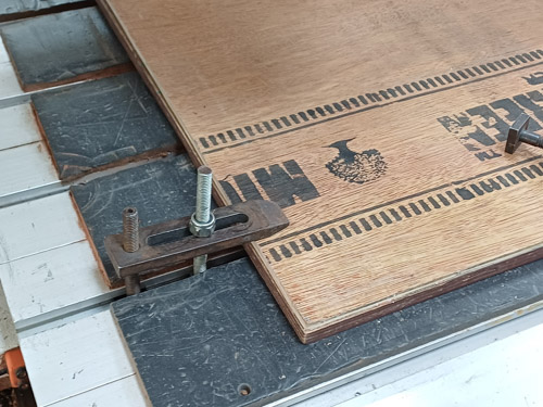
We used these clamps where one side fits into the groove on the bed and then the nut and bolt can be tightened to hold it in place.
Once the toolpath is made and post processed into an mmg file, simply take copy the mmg file onto a pendrive and take it to the cnc machine.
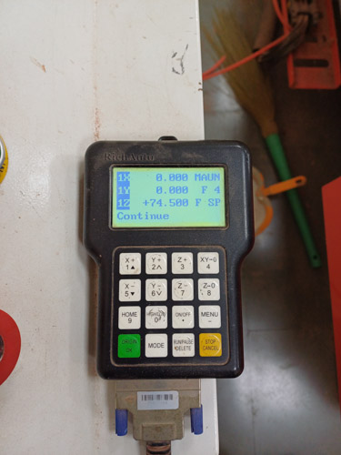
This is the controller of the machine. Insert the pendrive into this and select the file. Next, enter the Speed and Feed, and set the origin.
The XY origin can be set to the corner of the bed at the same point as the one set in the Toolpath file.
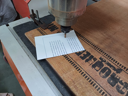
For the Z origin, we use the paper method. Slowly bring down the router until the tools tip touches the stock. Now, raise it up by the smallest amount possible on the controller and insert a thin piece of paper (pritner paper works) underneath it and being sliding it along the stock surface.
Now, we will adjust the Z height such that there is just enough friction between the tool and paper. The paper should be able to slide and you should be able to feel the friction of the tools tip on the paper as you drag it.
My assignment- Bench
I wanted to make a chair for this weeks assignment. And I wanted to apply my learnings of the Parametric week to make an “Easy to assemble, Parametric chair”.
I began by straight up chopping some good cardboard and fitting it together. This was my first chair:
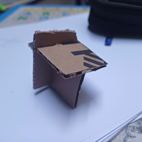
Simple to do and simple-looking too!
..but there was one problem:
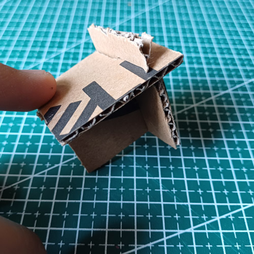
The chair would tilt if there was too much pressure applied on one side. That meant that if a person sat along the edge of the seat, they would fall and the chair would topple.
So I began rethinking my idea and imagined a much bigger seat- a BENCH!
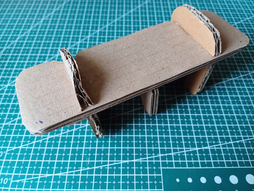

Once again, I made the cardboard model and showed it to my professors once I fould the proportions to be apt.
They pointed out that the middle leg was entirely unnecessary.

So in the CAD model, I got rid of the third leg

Quick tip here: If you want to quickly rearrange parts on fusion based on your assembly, you can use the Joints feature. This will allow you to simply select two planes and then press GO, and the software will automatically reposition the parts such that the two planes are in contact. This helped me especially for matching the slots of the parametric design.
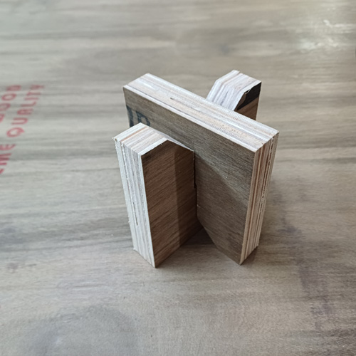
For the joints, I have made slots on all parts and when they fit together, the slots go into each other. This is similar to the parametric contruction kit from Week 3.
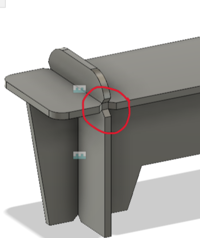
I decided to give chamfers at the entrance of the slot to make it easier to put the slots into each other. To balance out the chamfers of the slots, I gave chamfers/ V-shaped cuts on the side which overlapped with the chamfer of the slot.
For the clearance of the slots, I chose to give a 1 mm clearance. The slot was 26mm wide while the ply I wanted to use was 25mm.
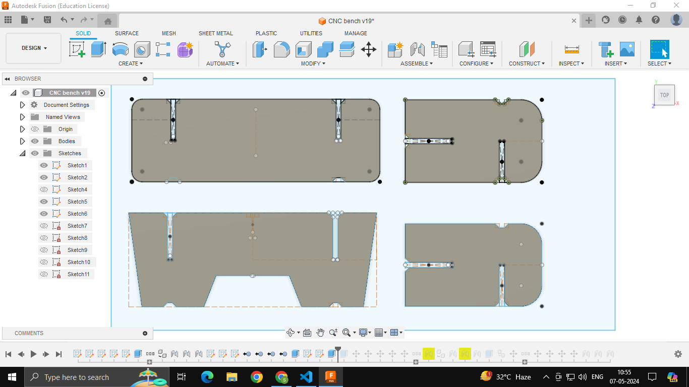
This is how my parts looked on the machine bed.
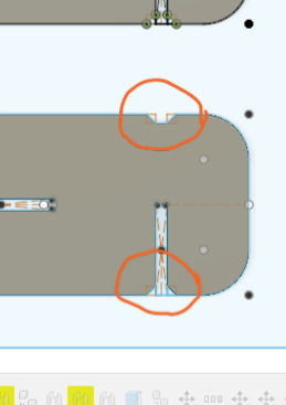
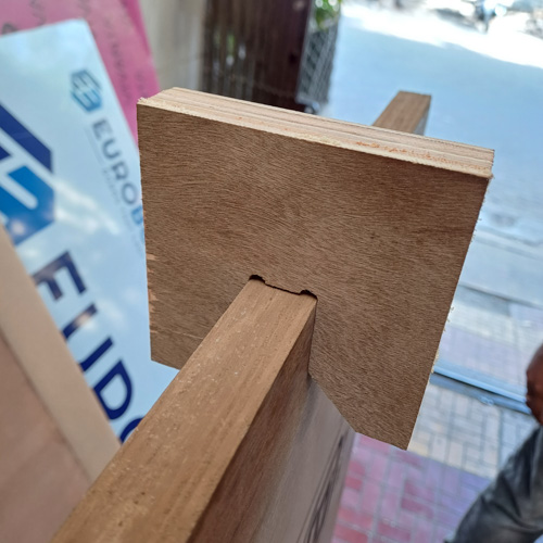
In my design for the slots, I have used Dogbones.
Dogbones or T-bones are when you give a circular offset to your corners (especially when you have slots). You do this because the router has a circular tool, meaning sharp edges are impossible. Hence, you make the circular offsets so that when routing, your tool goes beyond the corner allowing you to use the corner effectively. Without dogbones/tbones, your slot will go useless as the corner would be rounder inwards not allowing the other part to fit into it.
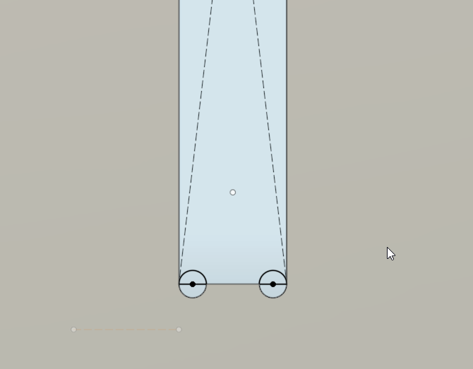
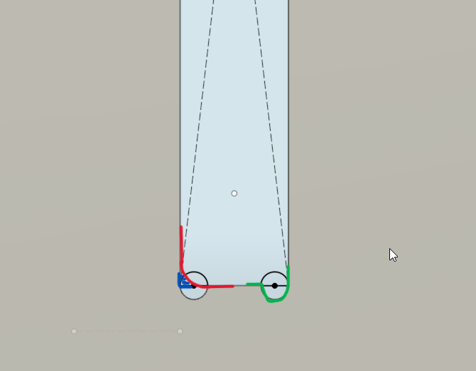
Here, the red indicates the curved corner without dogbone, where the green shows the corner with dogbones.
Machining
First Challenge
When the day of the cutting arrived. We did a small trial cut of a ring (as mentioned above “Trial Cut” section). During the air trial, the movement of the router was stuttered and jittery. This would have damaged the ply and the tool had we goe ahead with it.
Hence, we decided to get it cut from another facility.
Second Challenge
After exporting my fusion sketch as a DXF, I opened it on Adobe Illustrator to verify if that the DXF was right. To my surprise, the construction lines of the fusion file were also present.
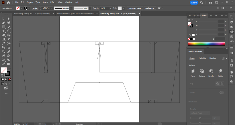
To counter this and to have only the body outline exported, I went into fusion and did the following:
- First take the sketch made and extruded it to make the solid body (I had already done this before when checking the joints)
- Next, select the face you want the sketch from and press ‘P’. That will project your face onto a new sketch. Now, select ‘Done’ and there you have it- a projected sketch of the body face!
Third Challenge
I had given a clearance of 1mm in my design file, meaning the slot was 26mm and the thickness of the part fitting in it was 25mm but the vendor told us that we will have to actually measure the arriving ply to get the exact slot/thickness measurements. He said that the ply though sold at 25mm may be ±1mm. Hence measuring it would be safe.
So we did a slot test when the ply arrived.
Here, you can see the 1-2 mm gap in the fitting:
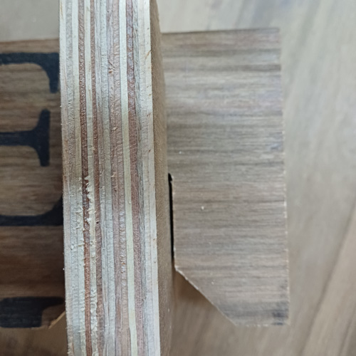
This meant that the ply was way less than 25 mm.
I used this test slot and ran it across my stock.
At the center, it is too tight:

At the corners,it is a decent fit:
I observed that the slot fit a bit loosely towards the corners and it got tighter as we moved towards the center of the ply. Near the center, the slot was small for the thickness of the ply.
I wanted to give it slots and wanted to make sure that is was stable and smugly fit.
But the ply was uneven. Upon measuring the ply, I saw that some places measured 23 mm, while some measured 22.5 mm (edges usually) and some 23.5 mm (center area) in thickness.
We went ahead with a slot size that would generally fit well – 23 mm.
And the machining process began!
The tool we used was an 8mm endmill
Using nails:
As mentioned before, it is very important to secure the part being cut.
To do so for my bench, we used nails and hammered it down in key areas such as the center of the part. The nail would go through into the sacrifical layer lying below. This was done to prevent the part from moving around once the machining was almost done. We used more than one nail for each part so that they don’t move ANd they don’t rotate!
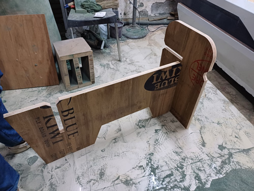
Assembly
Once machined, I manually sanded the slots a bit so that they finally fit snugly together.
We began assembling it:

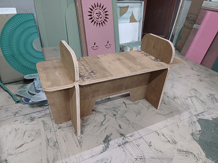
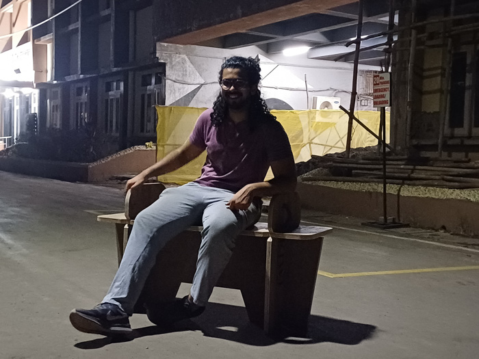
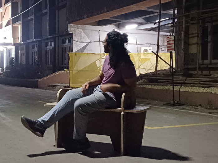
Once assembled, it stood well and sturdy:

Lessons
User considerations:
The ability to lift the bench and move it around. The design should be such that you can lift it easily (basically have a handle, and this could easily be made in the two horizontal sheets- the top part of the legs could have holes in them which would act as a handle for carrying the bench around). I missed taking this into account while designing but realized later on when I carried the bench myself back to the lab.
Form of the bench:
The bench’s physical form was very Brutalistic and boxy in nature. I could have considered having an intricate pattern on the sides and even trying out some curved surfaces to make the bench look more interesting.
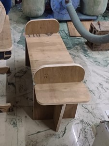
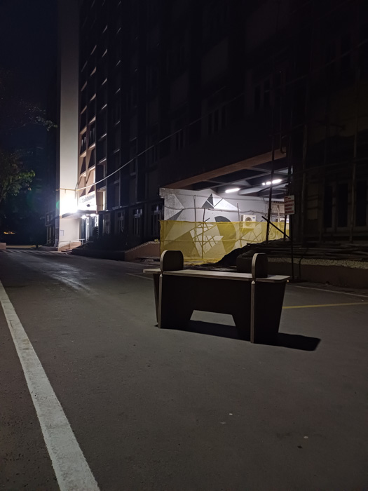
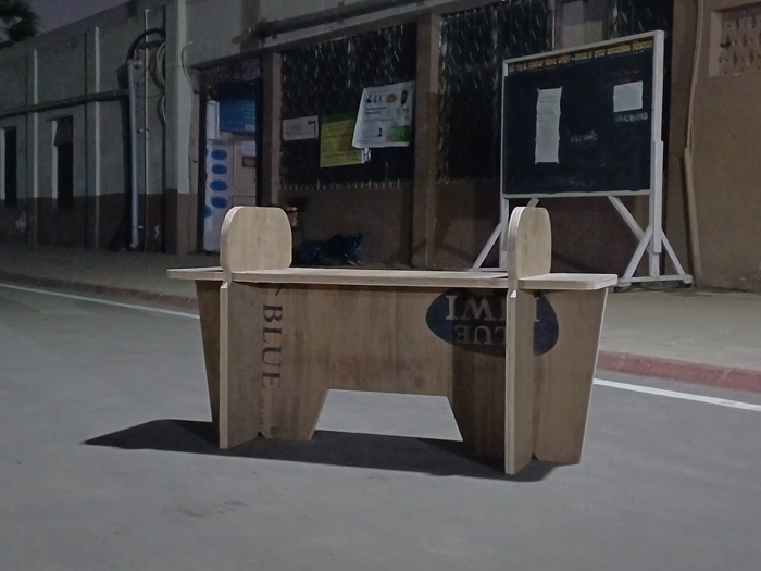
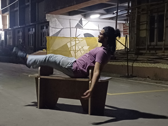
‘Batman’ shots
These are the Hero Shots we clicked at night time after returning from the vendor. Hence the name ‘Batman’. xD

Design files
The slot test was assuming the ply as 25mm, hence slot width of 26 mm (1 mm extra for clearance)
Ledio Router CPS