5. 3D printing and 3D scanning!
This week’s documentation is divided into three parts:
-
Group work- Doing tests for determining the design rules
-
Individual Printing - Chainmail Fabric attempt
-
3D scanning
Design Rule Determination: [Group work]
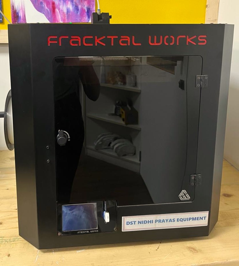
Our lab makes use of the Fracktal Works Julia Extended model.
PLA tests
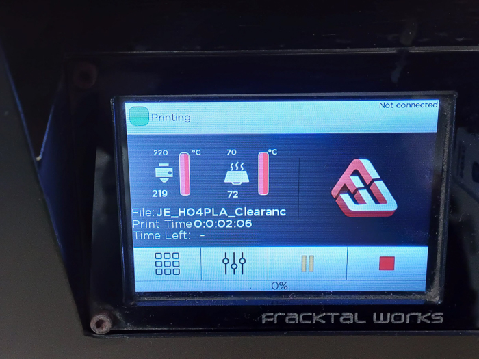
Material: White PLA.
Nozzle Temp : 220 C
Bed Temp : 70° C
Layer Height : 0.16 mm
Infill : 20%
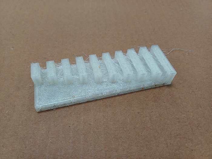
Angle test PLA
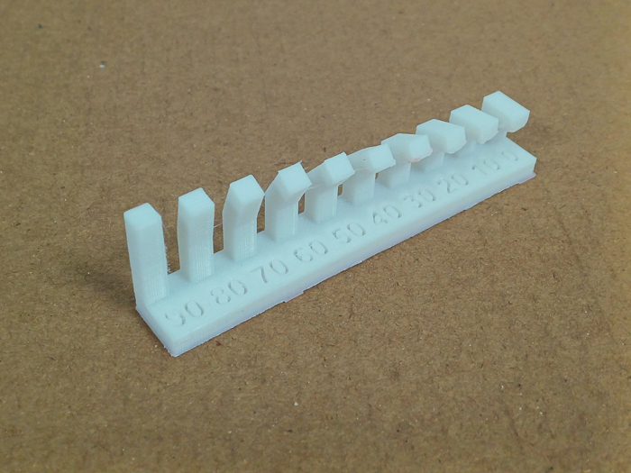
Angles up to 40° are good without support. Angles below that tend to get lumpy.
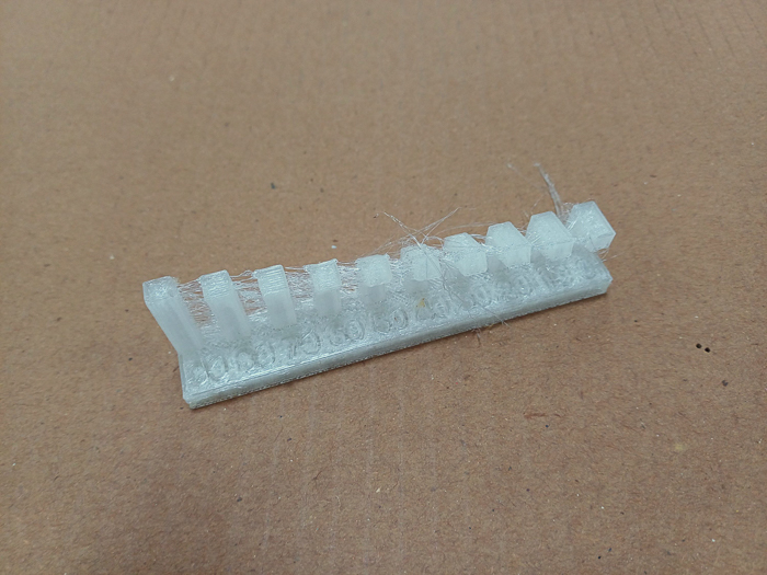
Wall Thickness test PLA

Actual Base thickness 4.92 mm
| Desired value | Actual Value of Slot | Actual Value of Peg |
|---|---|---|
| 3 mm | 2.96 mm | 3.8 mm |
| 2 mm | 1.9 mm | 2.16 mm |
| 0.7 mm | 0.74 mm | 0.75 mm |
| 0.6 mm | unmeasureable | 0.75 mm |
| 0.1 mm | unmeasureable | 0.6 mm |
Bridge test PLA
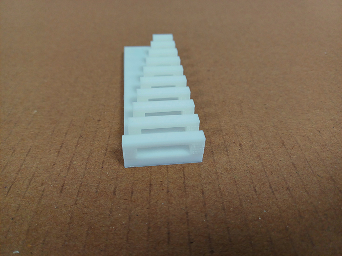
Unsupported bridges up to 20 mm are good to go.
Clearance test PLA
![]()
0.1 and 0.2 are attached to the rod.
TPU tests
Material: TPU
Nozzle Temp : 240 C
Bed Temp : 70° C
Layer Height : 0.16 mm
Infill : 20%
Angle test TPU
All the angles seem okay, except the 0 degree.
Wall Thickness test TPU
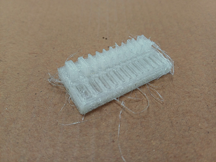
Actual BAse thickness 5.5 mm
| Desired value | Actual Value of Slot | Actual Value of Peg |
|---|---|---|
| 3 mm | 2.9 mm | 3.2 mm |
| 2 mm | 1.8 mm | 2.1 mm |
| 1 mm | 0.6 mm | 1.2 mm |
| 0.5 mm | unmeasureable | 0.7 mm |
| 0.4 mm | unmeasureable | 0.6 mm |
| 0.3 mm | unmeasureable | 0.55 mm |
| 0.2 mm | unmeasureable | 0.55 mm |
| 0.1 mm | unmeasureable | 0.5 mm |
Bridge test TPU
All the bridges seem fine.
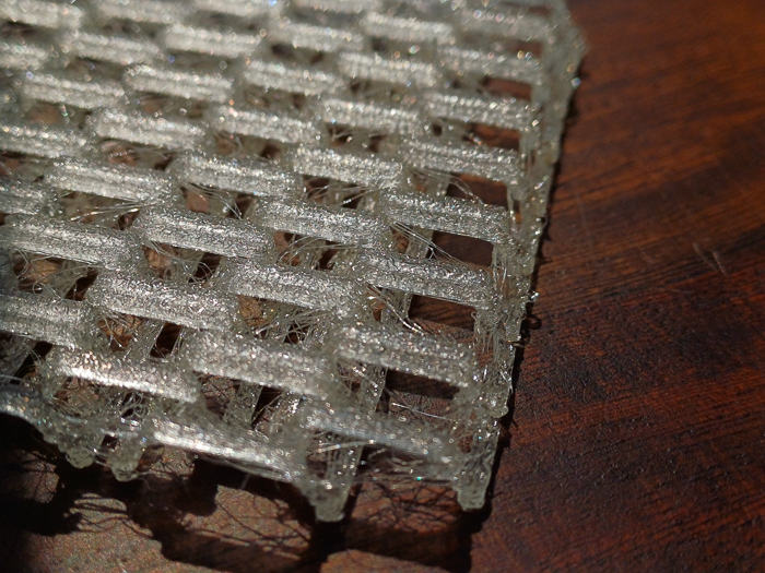
Here, we see that the TPU tests are heavily stringing. This could be because the Fracktal 3D Printer uses its in-built settings for temperature which may be too high for the TPU. It was observed that manually changing the temperature did not help as the printer automatically reset the temperature to its in-built TPU default (i.e. 240 Nozzle, 70 Bed).
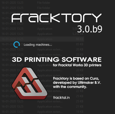
G-code generation:
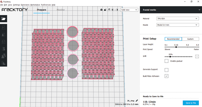
Since the printer is a Fracktal Works model, we use the Fracktory software to generate the gcode.
First, in order to set up Fracktory, you need to choose your printer. Go on to “Add Printer” and select your model.


Next, you can simply drag and drop the STL file, else open it via the File option.
Then, select your Material and Nozzle width. We were usign PLA and our pritner has a nozzle of 0.4 mm.
You will also select your layer height, infill density, and temperatures.
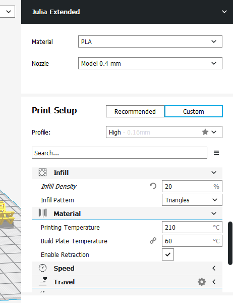
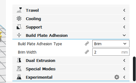
You will also be giving a build plate adhesion such as Brim, Skirt, or Raft. The point of it so that strings of melted material (after the initial line that the extruder runs o the side when starting prints) doesn’t end up causing hindrance to the actual print. A brim or skirt is good enough for PLA and TPU. Raft is generally used for ABS, which also requires proper ventilation.
Then you can go ahead and Slice the model. Click Preview to get a glimpse of how the layers will be formed.
3D printing Assignment
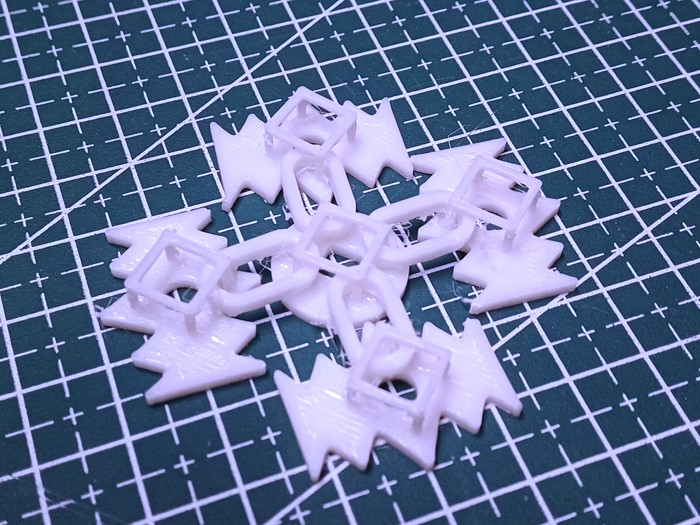
TPU Fabric / Chainmail
I was eager to try some sort of fabric design. I had seen and played around with some PLA chainmail that was lying around in the lab a year and a half ago (and when my hair was a bit shorter). I enjoyed the feel of the chainmail in my hands and it can’t be made by any subtracting process as the units of the chain interlink with each other in multiple axes. Also, no subtractive process will be able to remove aterial from all the sides.

I began with a simple chain mail structure. Created the sketch, extruded, combined and intersected, mirrored, and a couple of minutes later I had my basic chain unit.
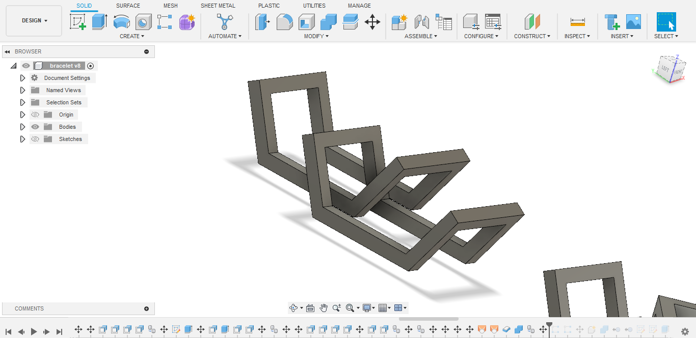
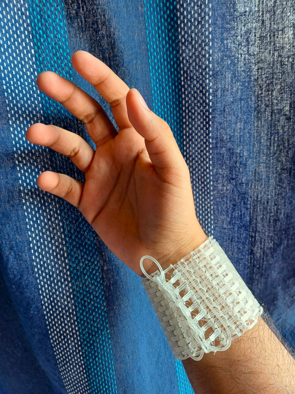
Now, I know that a chainmail is typically made in a non-elastic material to give it a feel of the fabric- something like PLA. But I wanted to use TPU to see how the elasticity plays out with the chain mail structure. I modelled the structure and gave it a couple of small rings which had a tiny slit. Since the material was TPU, the rings would simply stretch away allowing easy interlocking. The idea was to make a bracelet out of the rings and the chainmail.
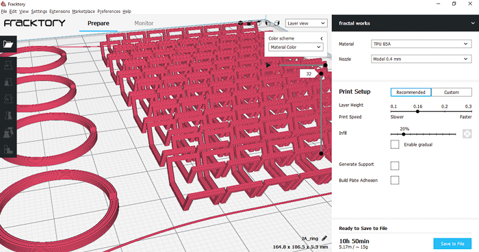
I set the infill to 100% and kept layer height at 1.6mm.


The outcome was decent. There a bit of stringing here and there and perhaps I could have given a greater thickness of individual unit (right now it was just 2mm).

The rings turned out a little too flexible and acted more like a thread rather than a ring. This made it difficult to use them to hold the two pieces of chainmail together.
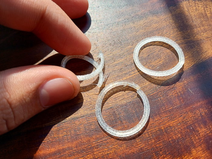
So I had to work around that. I found some spare filament lying around in class and thought that it could be used to bind the chainmail.

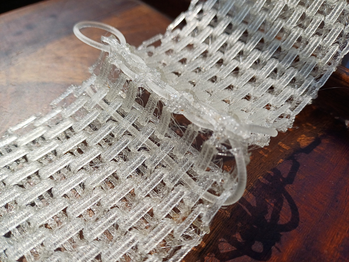

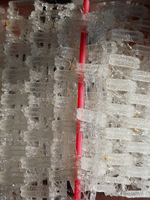
Final ‘Hero’ Shots:


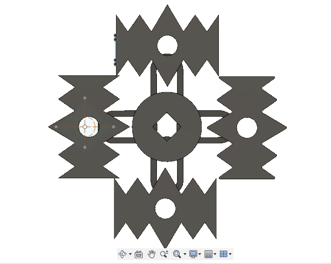
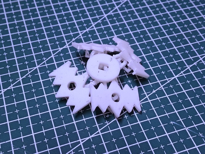
Other Fabric Explorations (In progress)
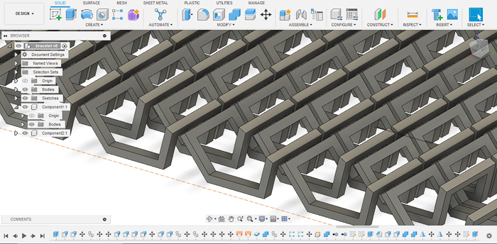
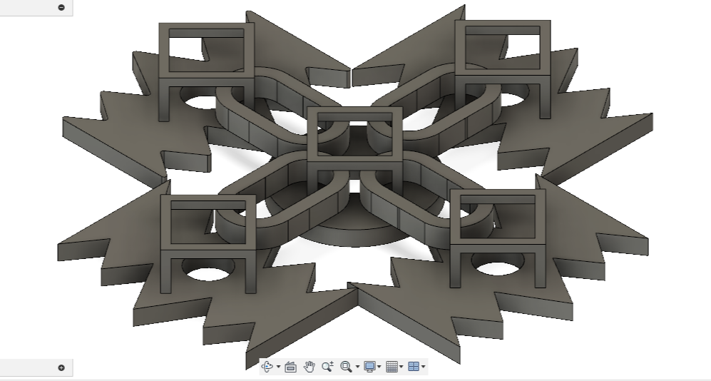
I also looked up a bunch of videos on how different 3D printed fabrics are made (I’ll link them below) and modelled some custom pieces.
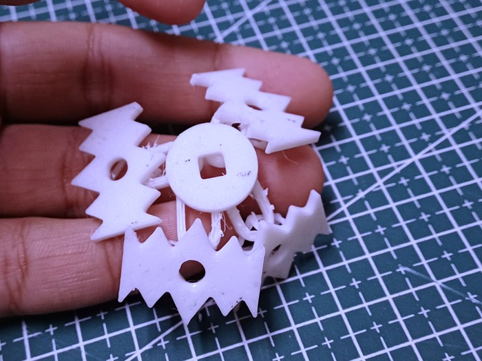
These pieces would tesselate and be linked on the underside as shown in this:

However, I could get these individual pieces of the fabric to link and am still figuring that out.

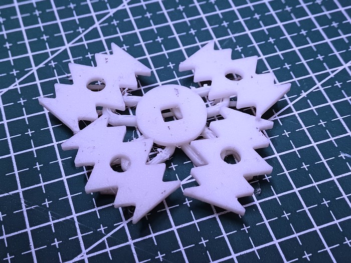
Update:
So I did go ahead and figure it out, and here’s how it looked!:
Useful Links!
- The smart chain mail fabric that can stiffen on demand
- Make 3D Printed Fabric | STEM Activity
- How to 3D print fabric - Step by step
- TPU 3D Printing: A Guide to 3D Printing Flexible Parts
-
Tutorial: Create Your Own 3D Printed Bracelet in a Matter of Minutes
- 3D Printed Bracelet
- 3d Printed Bracelet For G-shock 16mm Lug
3D scanning Assignment
Kiri Engine app- Mobile phone
Kiri Engine was actually quite fun to use. And it worked pretty well! (with reasonable processing time)
Clay face scan
The actual model hand-made in clay by me

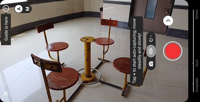
Bench scan
The actual Bench
Process:
Quick comic moment here: As I was opening Kiri, I glanced at my screen and proceeded to do some other work on the side. I looked at this screen and noticed the loading bar on the top. 5 minutes past and I glanced back at my phone and saw that the loadign bar was still at 2/5th the way. Frustrated, I tapped on my phone screen rather voilently and voila! It changed to the next slide. It had never been a loading screen, instead you swipe to see the next screen xD
Starting out (after logging in), click on the Plus Icon at the bottom to start a new scan:

Then click on Photo Scan:
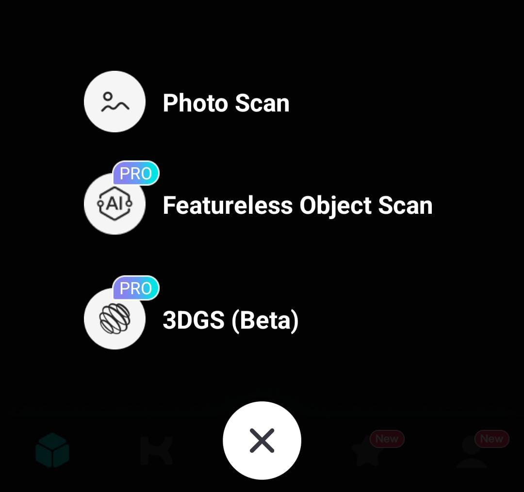
Finally, select the Take Photos option:

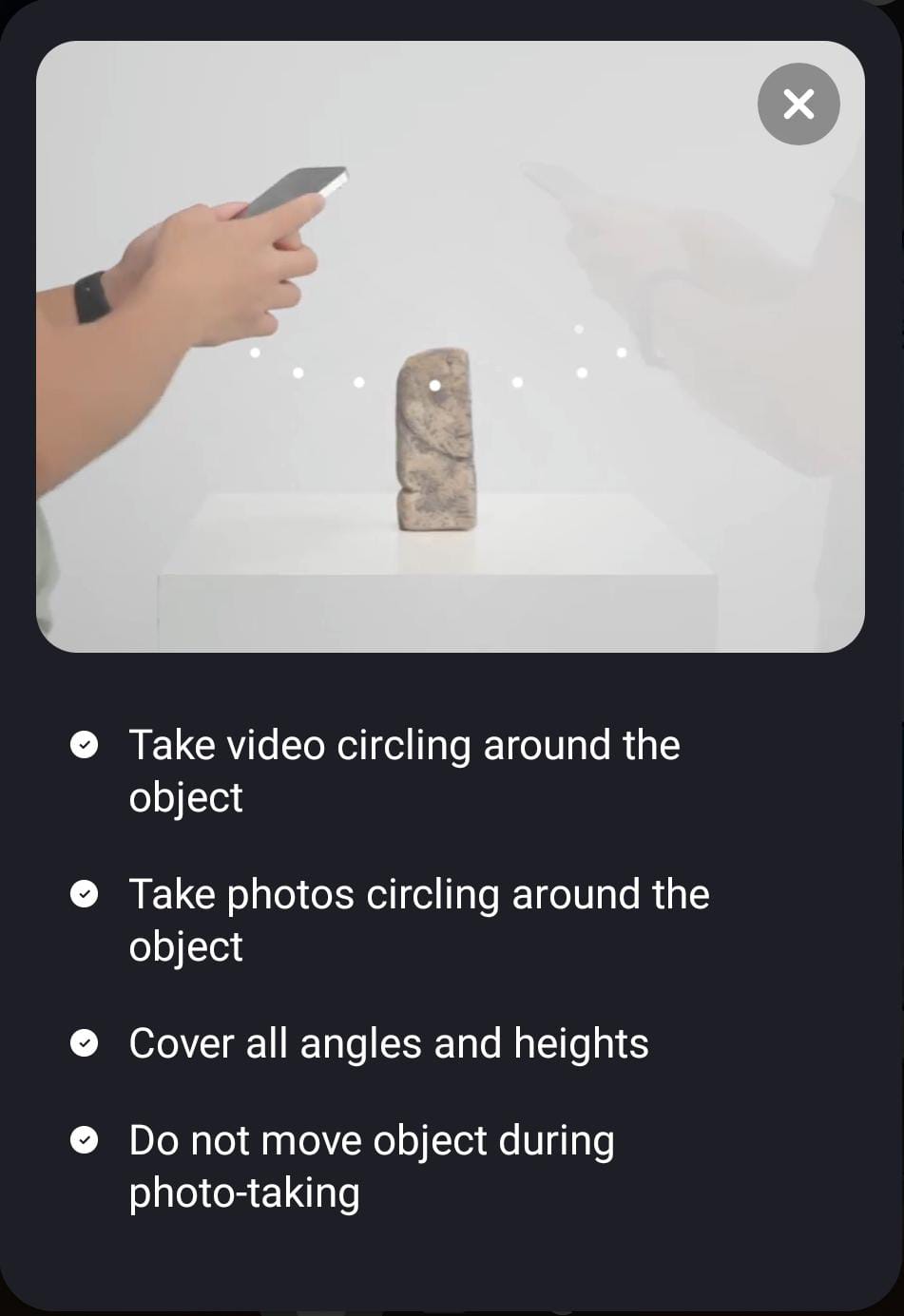
Next up, follow these tutorials that Kiri will show you before you 3D scan an object. You can choose to follow either of the methods or a combination of both.
METHOD 1: You rotate around the object with the camera in your hand. The object stays stationary:
METHOD 2: You and the camera stay still and you rotate the object around it’s own axis to capture different angles.
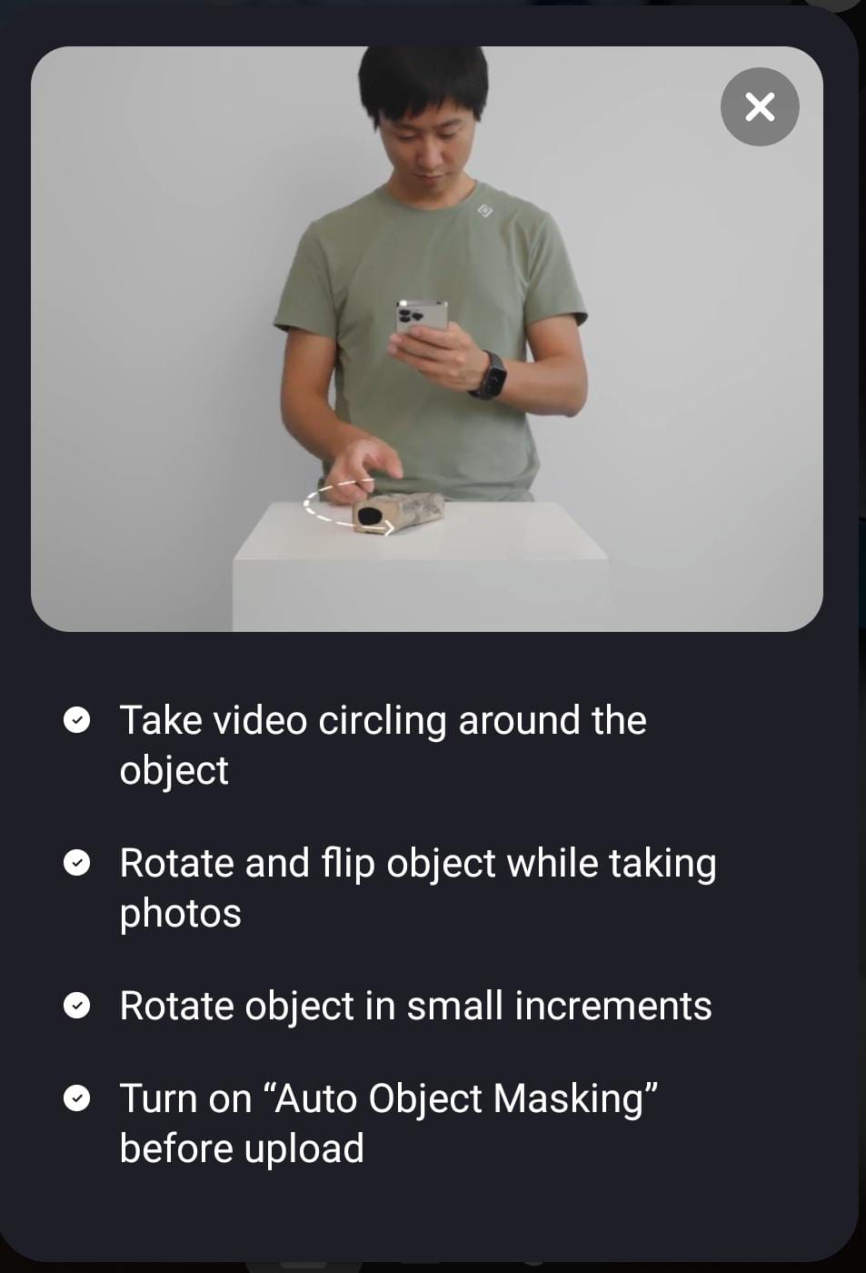
I have found that using Method 1 is effective if you have space to move around. If you don’t have space to move, you can use Method 2.
In Method 2, a quick trick is to place a large chart paper or sheet underneath the object and rotating the chartpaper. Make sure that the edges of the chartpaper is out of your camera frame. This is so that your hand doesn’t end up ruining the scan as you rotate the object without the chartpaper.
Make sure to hold your phone at a constant height and angle when doing either of the methods. In Method 1, an easy way is to hold the phone close to your body and just focus on moving your legs. turn your whole body when circling- not just your torso. And remember that better lighting and a sharper phone camera will result in a better mesh!
There is also an option to take photos automatically, which is represented by this video icon. Make sure to use that to save time.

The linear scale at the bottom will also tell you if you are doing a good or mediocre job at scanning and you can adjust accordingly.
App screen after the model is processed:
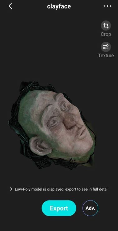
And Export!
Post-processing:
Once the scan is complete, Kiri engine will email you a zip file with the .jpg, .obj, and the .mtl along with low poly versions of the 3.
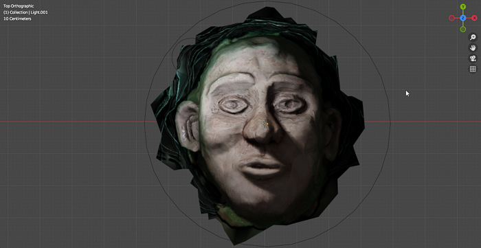
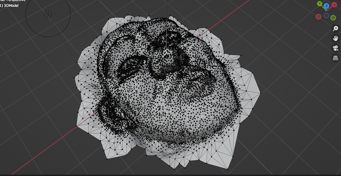
Next, I hopped on blender and imported the .obj and .mtl file. My goal was to clean up the Clayface scan a bit and remove the extra area around the base of the model.
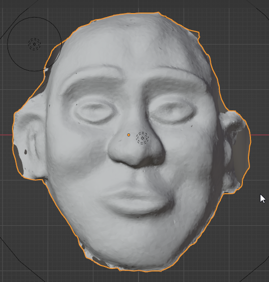
With Render Viewport and one light source. The texture and material of the scan turned out decent in the render viewport.
In edit mode, with vertex selection. Notice the number of vertices the mesh has.
I cleared up the vertex points of the base that jutted out of the sides of the body.
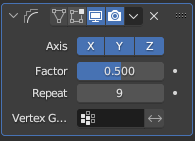
Next, I went ahead and added a smooth modifier to the mesh:
Before the modifier:

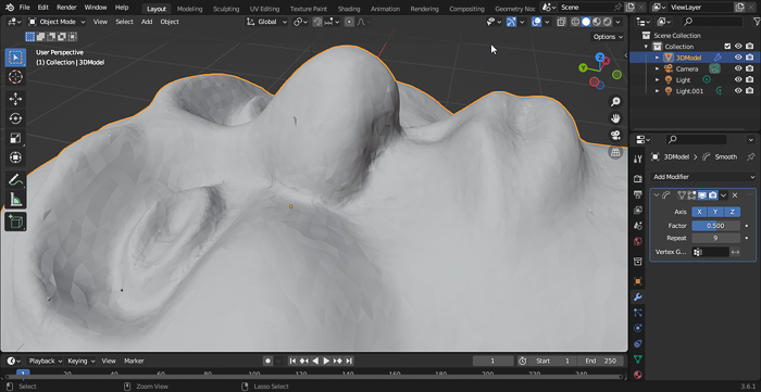
After the modifier:
Notice the smoothness and texture of the surface of the body after applying the modifier. Also, the base is cleaned up (as seen above)!
I have attached the Clayface Zip that Kiri sends you along with the Blender file where I modified the scanned Mesh In the Project Files section.
MagiScan app- Mobile phone
Magiscan was decent. Though the entire body did not get scanned entirely.
The actual chair

App showed a whopping 20 days to process, but ended up happening quicker

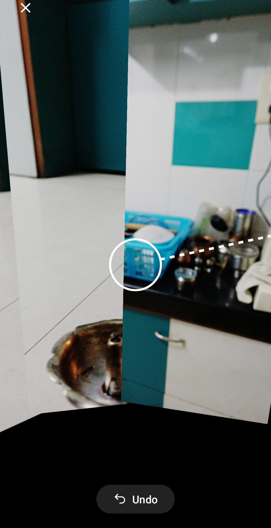
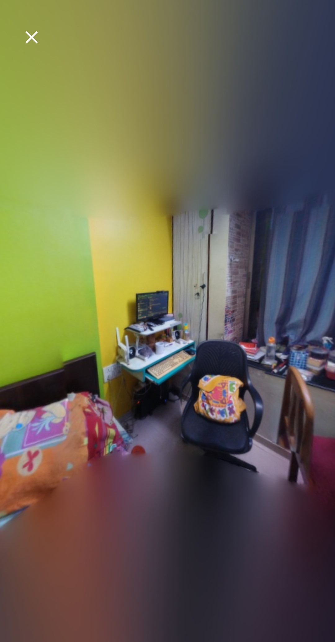
MatterPort - Scanning Rooms
Matterport seems effective in scanning rooms. However, it doesn’t work as effectively when scanning objects. To scan the room, you rotate staying in the center of the room. When scanning an object, the object remains in the center and you move around it.
Project Files
Basic Chainmail STL
Connecting Rings STL
Sharp-edged Fabric STL
All Fusion360 files
Kiri Zip file of “Clayface”
Modified Blender file of “Clayface”