Input Devices
In electronics, input devices are components or systems that allow users to input data or signals into a device or system. These devices detect and convert physical or analog signals into digital signals that can be processed by electronic circuits or systems. Input devices can take various forms depending on their intended use, including sensors, switches, keyboards, mice, touchscreens, microphones, cameras, and more. They play a crucial role in interacting with electronic systems, enabling users to provide commands, data, or information for processing or control.
Types of Imput Devices
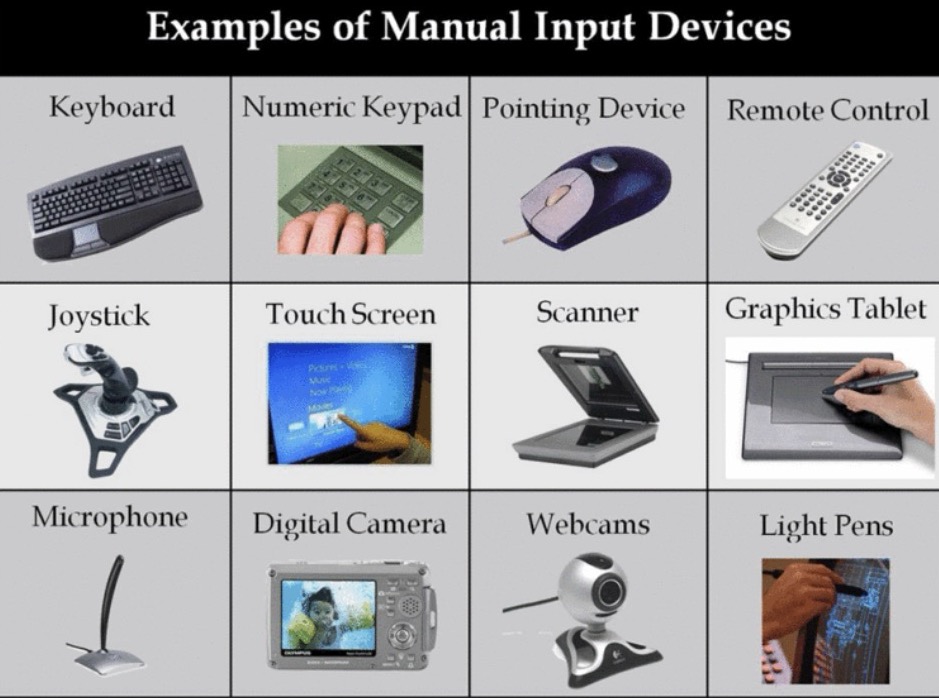
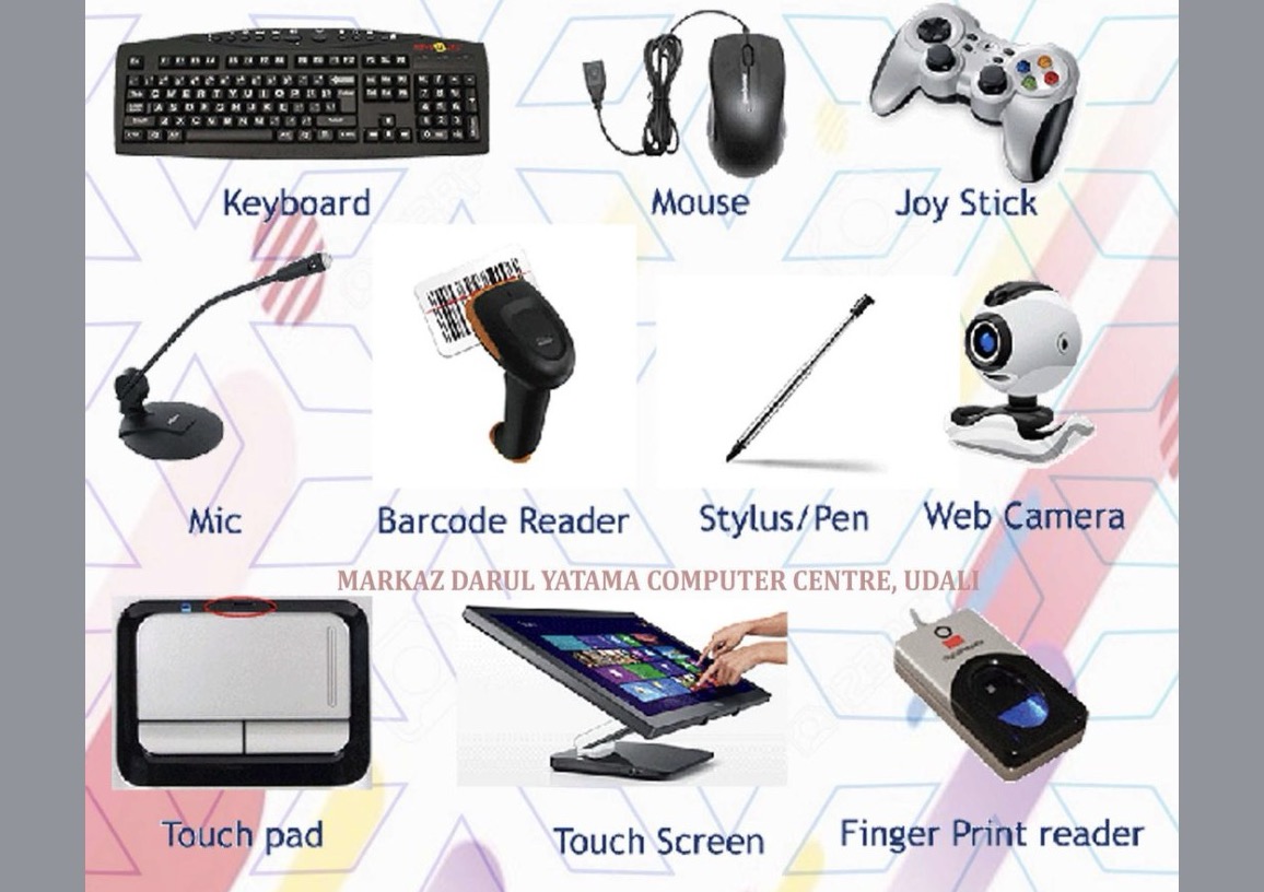
Manual Input Devices:
These devices require direct physical interaction from a user to input data. Examples include keyboards, mice, trackballs, joysticks, game controllers, and touchpads.
Group assignment:
Probe an input device(s)'s analog levels and digital signals
Document your work on the group work page and reflect on your individual page what you learned
So we learned about oscilloscope and how does it works in week 8 and the entire documentation of oscilloscope is Here.
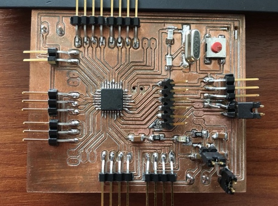
In this week we used tejas's input device that was a speaker attached with rp2040 seed studio xiao, entire documentation of the imput device can be viewed at Tejas's Page.
code
Below is the code that he used for this week
    // Pin definitions
const int soundSensorPin = A1; // GPIO 0 for sound sensor

// Threshold for sound level to detect speech
const float speechThreshold = 39.0; // Adjust this threshold as needed

void setup() {
  pinMode(soundSensorPin, INPUT);
  Serial.begin(9600);
}

void loop() {
  // Read the analog value from the sound sensor
  int soundValue = analogRead(soundSensorPin);

  // Convert analog value to decibels (assuming linear relationship, may vary with sensor)
  float soundDecibel = 20 * log10(soundValue);

  // Print the sound level in decibels to the serial monitor
  Serial.print("Sound level (dB): ");
  Serial.println(soundDecibel);

  // If sound level exceeds the speech threshold, turn on the LED
  if (soundDecibel > speechThreshold) {
  Serial.println("Loud");
  } else {
  Serial.println("Quiet");
  }
  // Add a delay to avoid flooding the serial monitor
  delay(500);
}
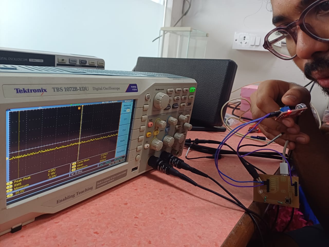
Following all the same steps of oscilloscope from week 8- electronic design we went ahead and tested his board by connecting probes to
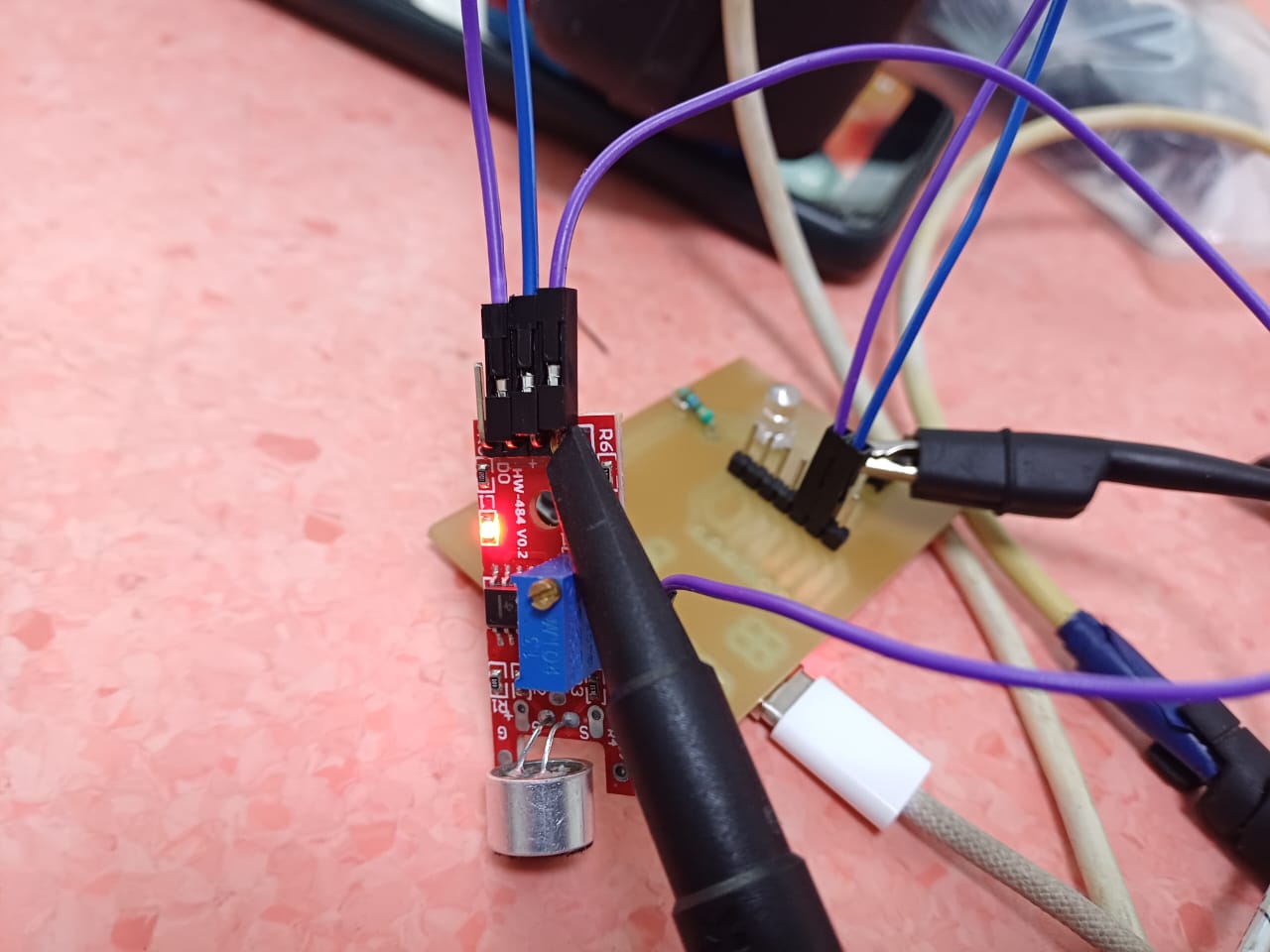
After that we were able to see the waves and readings as well. We went on trigger control and got the below readings
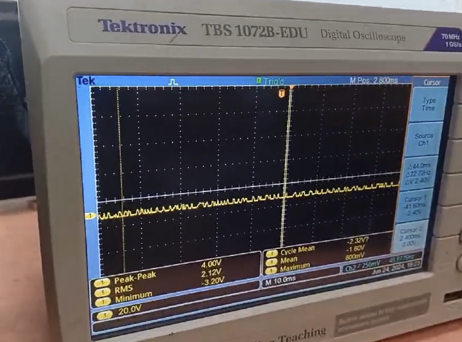
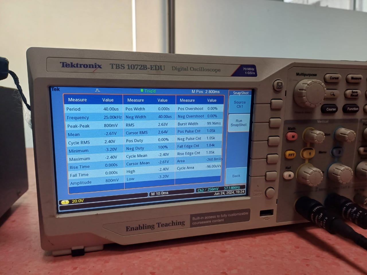
Heroshot
My personal Learnings
During the group assignment, I gained a deeper understanding of how to probe and analyze the analog levels and digital signals of an input device. Using a sound sensor with the RP2040 microcontroller, I learned how to interpret the sensor’s output and visualize sound waves. This hands-on experience improved my skills in using oscilloscopes to measure and troubleshoot sensor data.
Individual Assignment
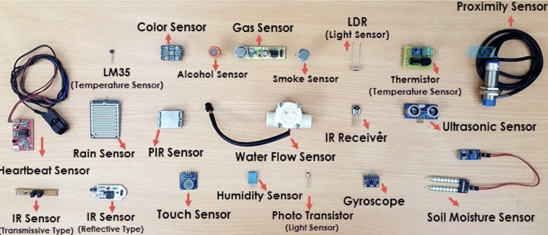
Sensors:
Sensors detect changes in physical properties such as light, temperature, pressure, motion, or proximity and convert them into electrical signals. Examples include photodetectors, temperature sensors, accelerometers, gyroscopes, proximity sensors, and pressure sensors.
Audio Input Devices:
These devices capture sound waves and convert them into electrical signals. Examples include microphones, audio transducers, and speech recognition systems.

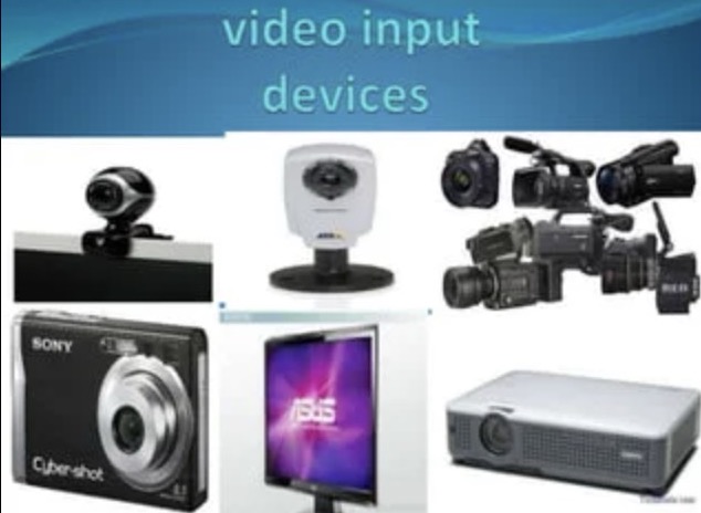
Video Input Devices:
Video input devices capture visual information and convert it into electronic signals. Examples include cameras, webcams, and scanners.
Biometric Input Devices:
Biometric input devices capture unique physical characteristics of individuals for authentication or identification purposes. Examples include fingerprint scanners, iris scanners, and facial recognition systems.
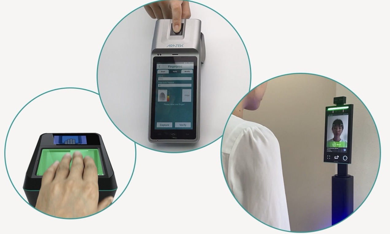
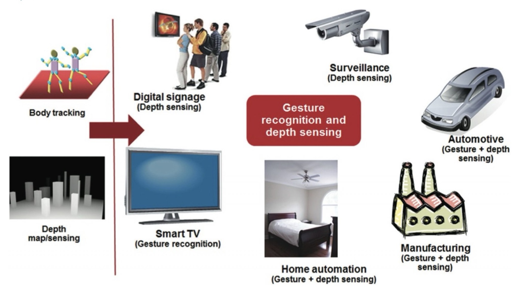
Gesture Recognition Devices:
These devices capture hand movements or gestures and interpret them as commands or input signals. Examples include motion-sensing cameras, depth sensors, and gesture-based input devices.
Touch Input Devices:
Touch input devices detect touch or pressure applied to a surface and convert it into electronic signals. Examples include touchscreens, capacitive touch sensors, resistive touch sensors, and stylus pens.
Ultrasonic sensor
An ultrasonic sensor emits high-frequency sound waves and measures the time it takes for them to bounce back from an object, determining its distance. It serves as an input device by providing distance or presence data to a system, enabling decisions or control actions. Commonly used in distance measurement, object detection, and obstacle avoidance, it plays a crucial role in robotics and automation applications.
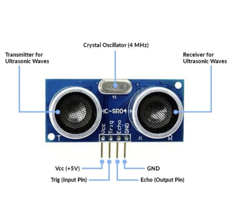
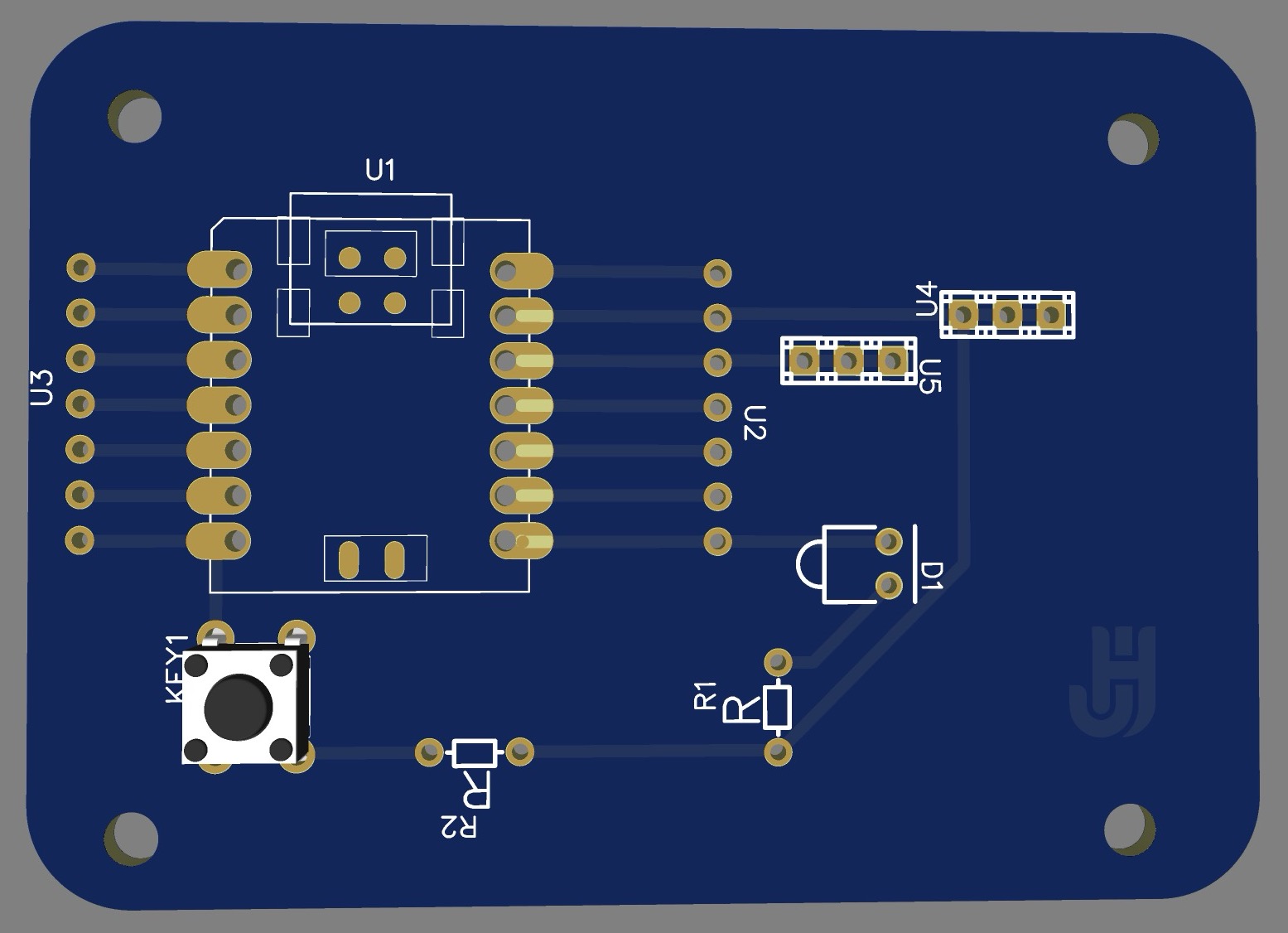
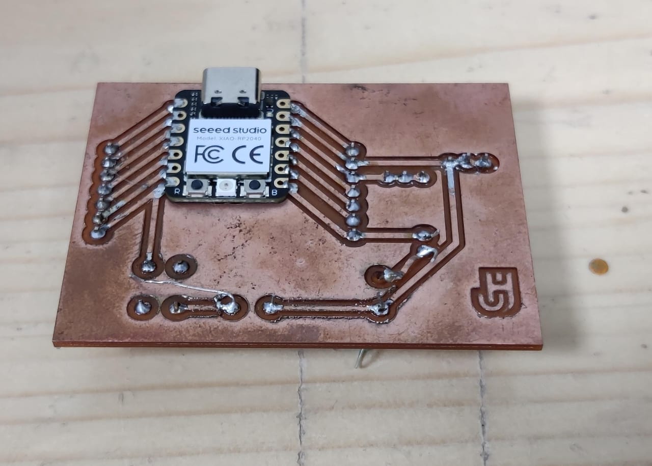
For this assignment, I'll utilize the HC-SR04 ultrasonic sensor as an input device. I'll integrate it with the final board I previously assembled, detailed in the Output devices assignment. Here are the images of the completed board from the earlier task:
The documentation of designing the development board and milling it is done in Week 8.
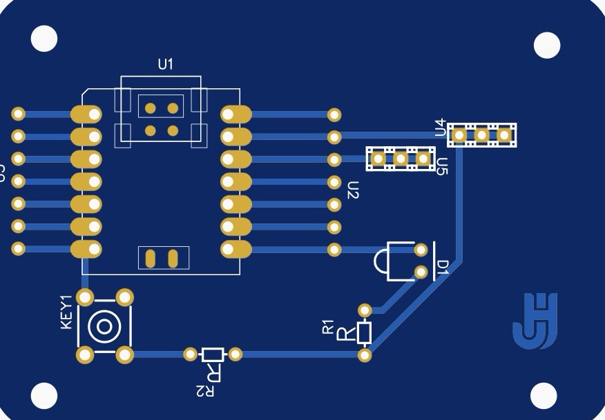
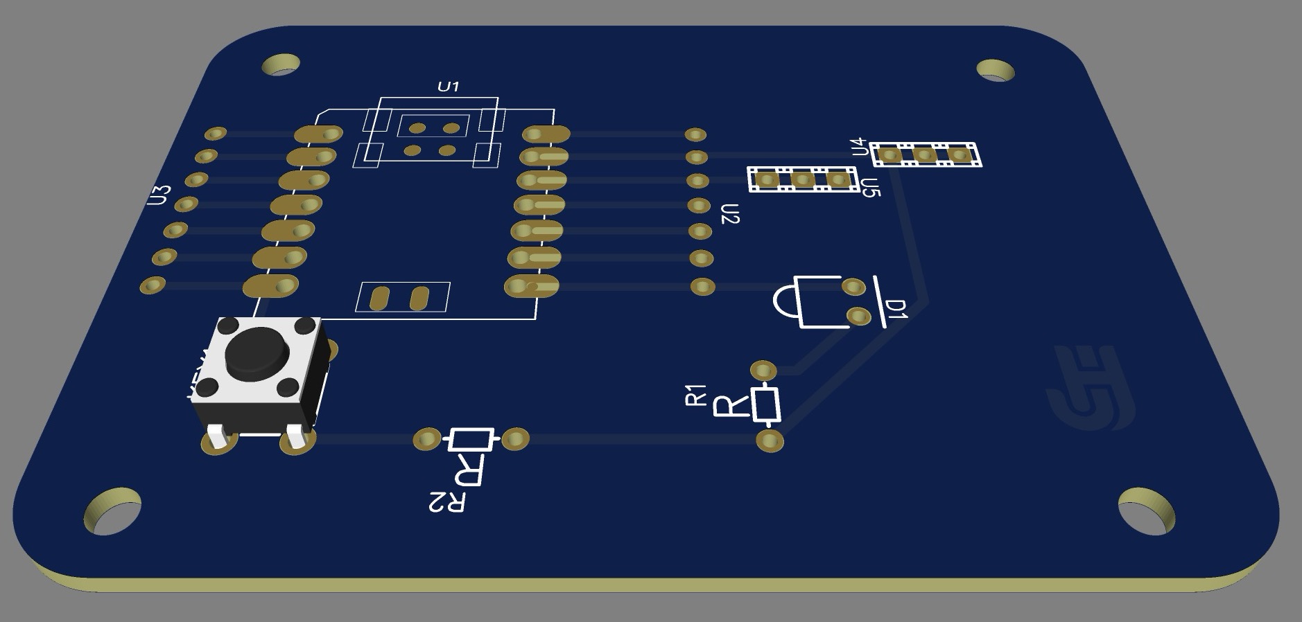
3d views
Below are the images of 3d views of my pcb board
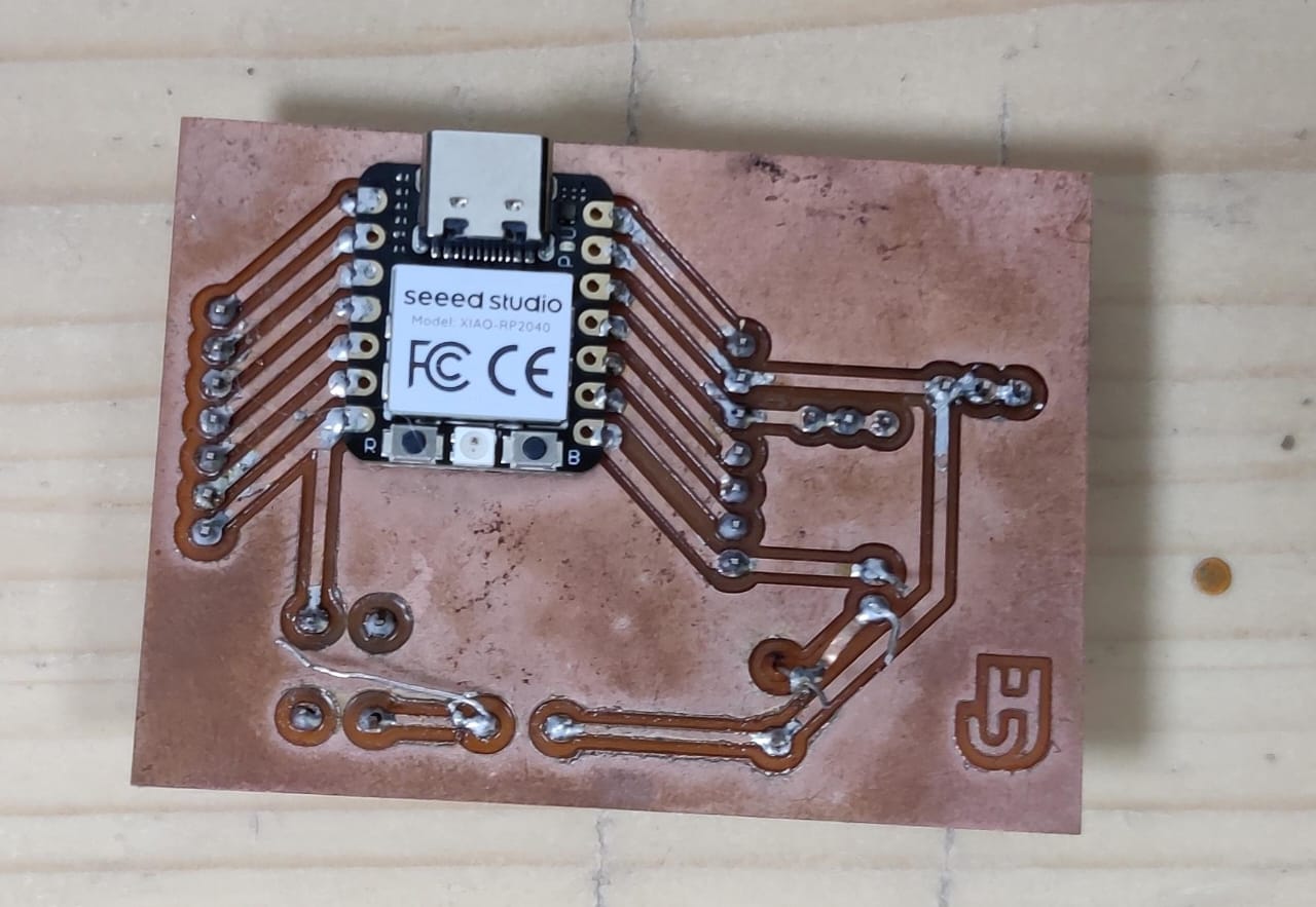
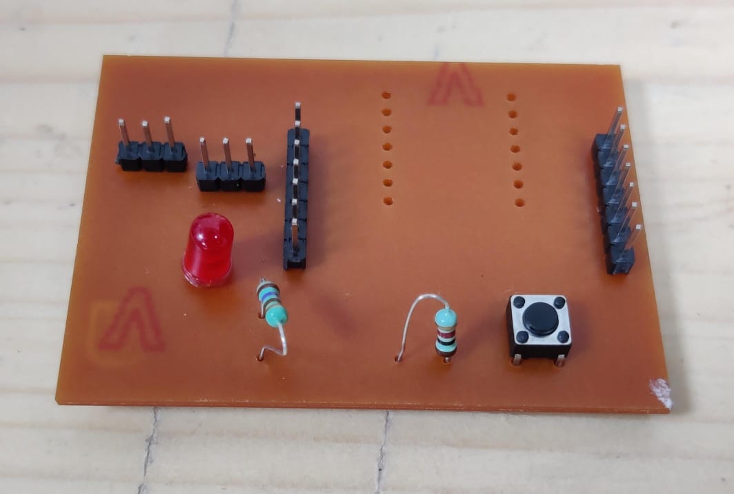
PCB board
This is how my board looks after milling.
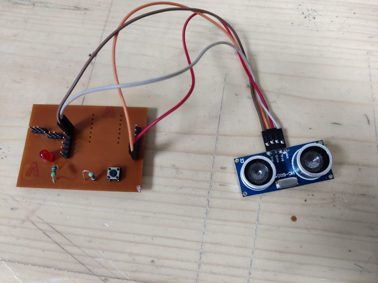
Connections
Ultrasonic Sensor:
- VCC pin to 5V on Seed XIAO RP2040
- GND pin to GND on Seed XIAO RP2040
- TRIG pin to digital pin (D5)
- ECHO pin to digital pin (D6)
LED:
- Anode (longer leg) to digital pin with resistor in series (D7)
- Cathode (shorter leg) to GND on Seed XIAO RP2040
Code
    #define TRIG_PIN D5
#define ECHO_PIN D6
#define LED_PIN D7

void setup() {
  Serial.begin(9600);

  pinMode(TRIG_PIN, OUTPUT);
  pinMode(ECHO_PIN, INPUT);
  pinMode(LED_PIN, OUTPUT);
}

void loop() {#define TRIG_PIN 5
#define ECHO_PIN 6

void setup() {
  Serial.begin(9600);

  pinMode(TRIG_PIN, OUTPUT);
  pinMode(ECHO_PIN, INPUT);
}

void loop() {
  // Trigger pulse
  digitalWrite(TRIG_PIN, LOW);
  delayMicroseconds(2);
  digitalWrite(TRIG_PIN, HIGH);
  delayMicroseconds(10);
  digitalWrite(TRIG_PIN, LOW);

  // Measure echo duration
  long duration = pulseIn(ECHO_PIN, HIGH);

  // Calculate distance in cm
  float distance = duration * 0.0343 / 2;

  Serial.print("Distance: ");
  Serial.print(distance);
  Serial.println(" cm");

  delay(500); // Delay for readability
}

  // Trigger pulse
  digitalWrite(TRIG_PIN, LOW);
  delayMicroseconds(2);
  digitalWrite(TRIG_PIN, HIGH);
  delayMicroseconds(10);
  digitalWrite(TRIG_PIN, LOW);

  // Measure echo duration
  long duration = pulseIn(ECHO_PIN, HIGH);

  // Calculate distance in cm
  float distance = duration * 0.0343 / 2;

  Serial.print("Distance: ");
  Serial.print(distance);
  Serial.println(" cm");

  // Check if distance is less than 5cm
  if (distance < 5) {
    digitalWrite(LED_PIN, HIGH); // Turn on LED
  } else {
    digitalWrite(LED_PIN, LOW); // Turn off LED
  }

  delay(100); // Delay for stability
}
Final Working
Final project pcb
In this week I have also done my final project pcb, imput/ output device both, here is in detail documentation visit my Final Project Page.
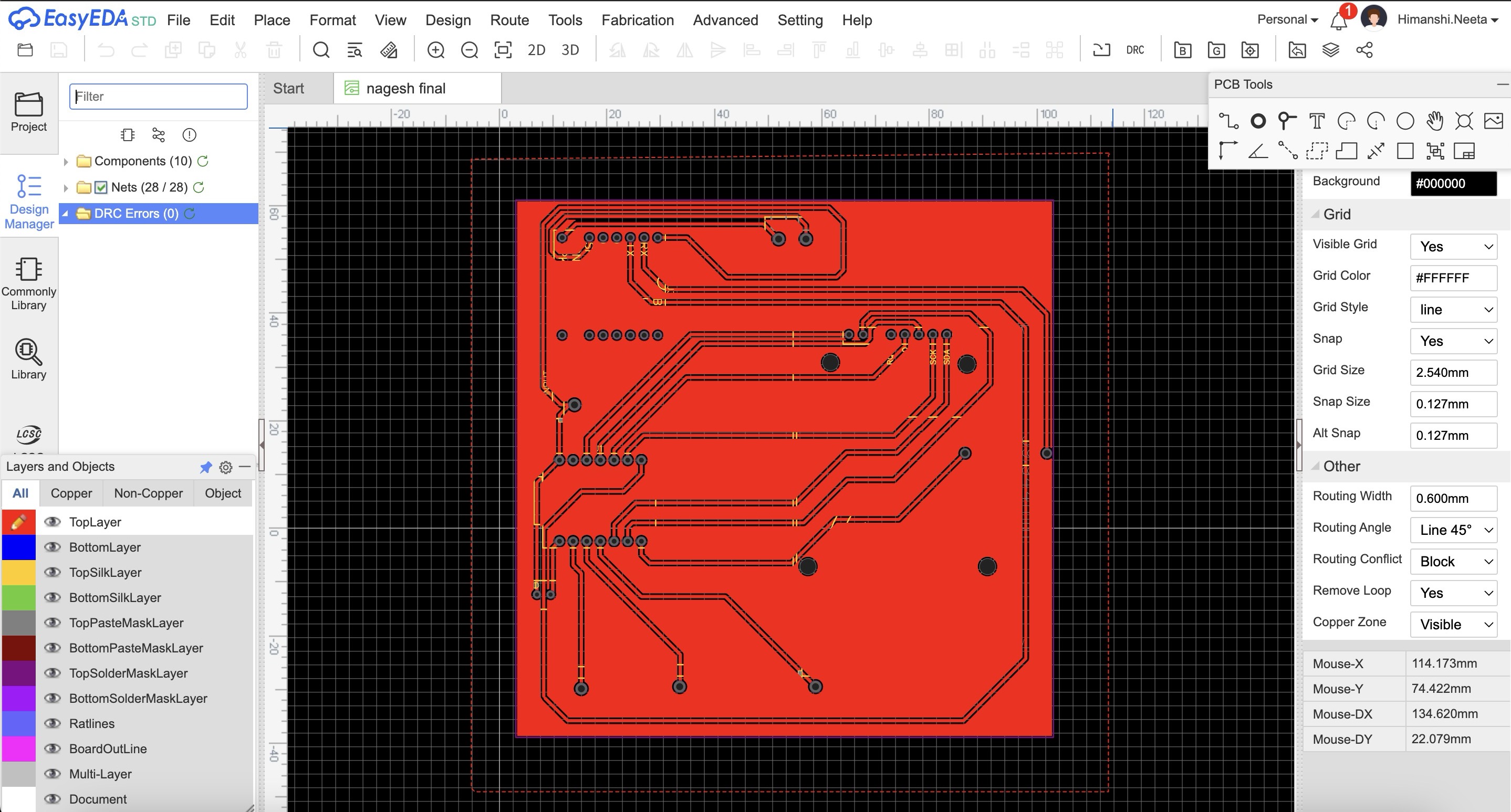
PCB design
After the placement of components were fixed I started with the pcb design. I did the pcb design on easyeda software to know how to use the software go on Week 8- Electronic Design..
Input Components:
The below mentioned components were my imput components which I used in my final project pcb.
Push Buttons:
Function: I used push buttons to receive input from the user, such as triggering an action like on, off or pause when pressed.
RFID Scanner:
Function: I used rfid scanners to read RFID cards when scanned, providing input data based on the tag information.
Potentiometer:
Function: I used potentiometer to adjust a volume up/ down parameter, by providing varying resistance based on its position.
Steps for making pcb
So step 1 was to make a schematic of the connections by taking components from library and making the connections after that is done save the file and go to convert schematic to pcb in design option which is on the top nav bar.
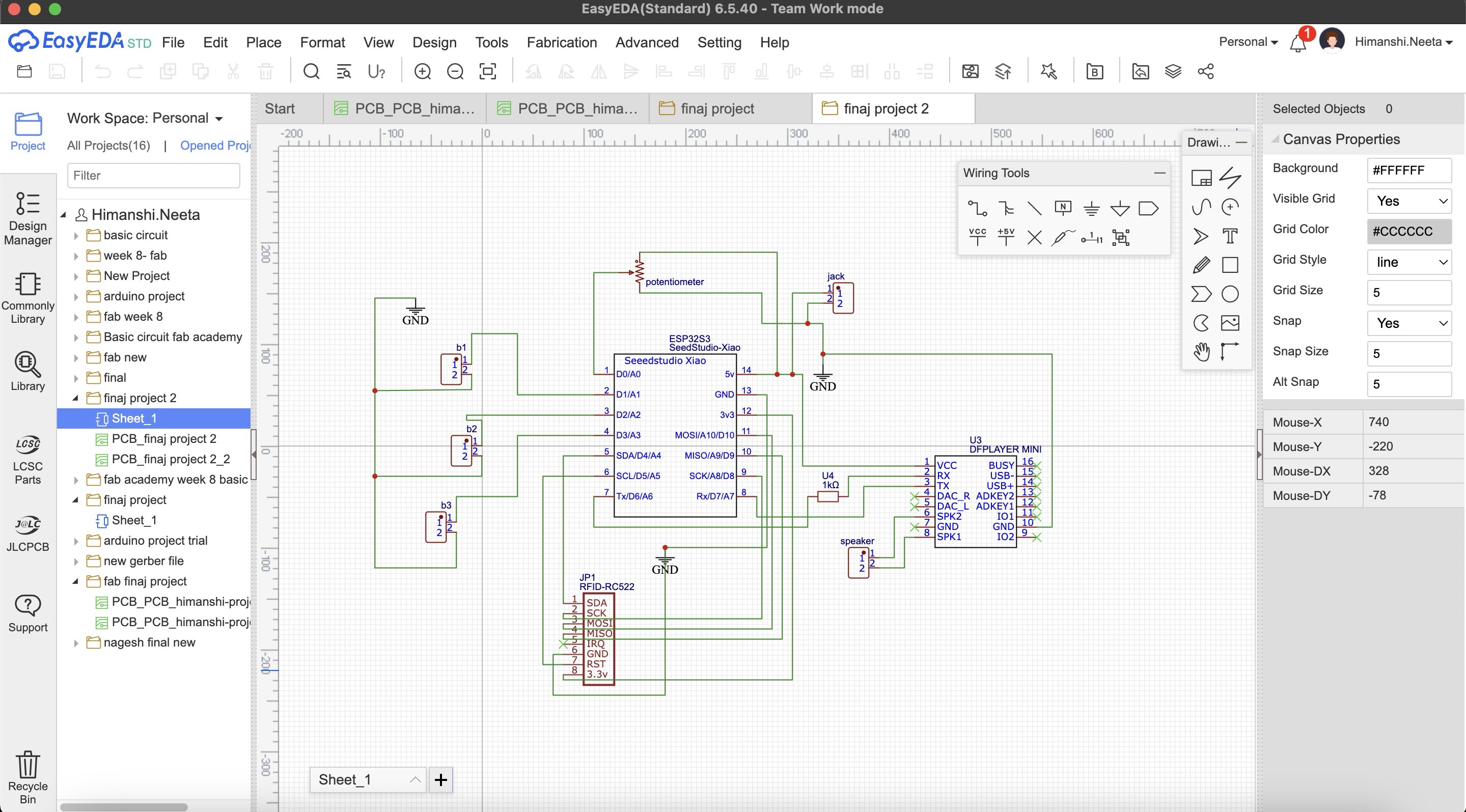
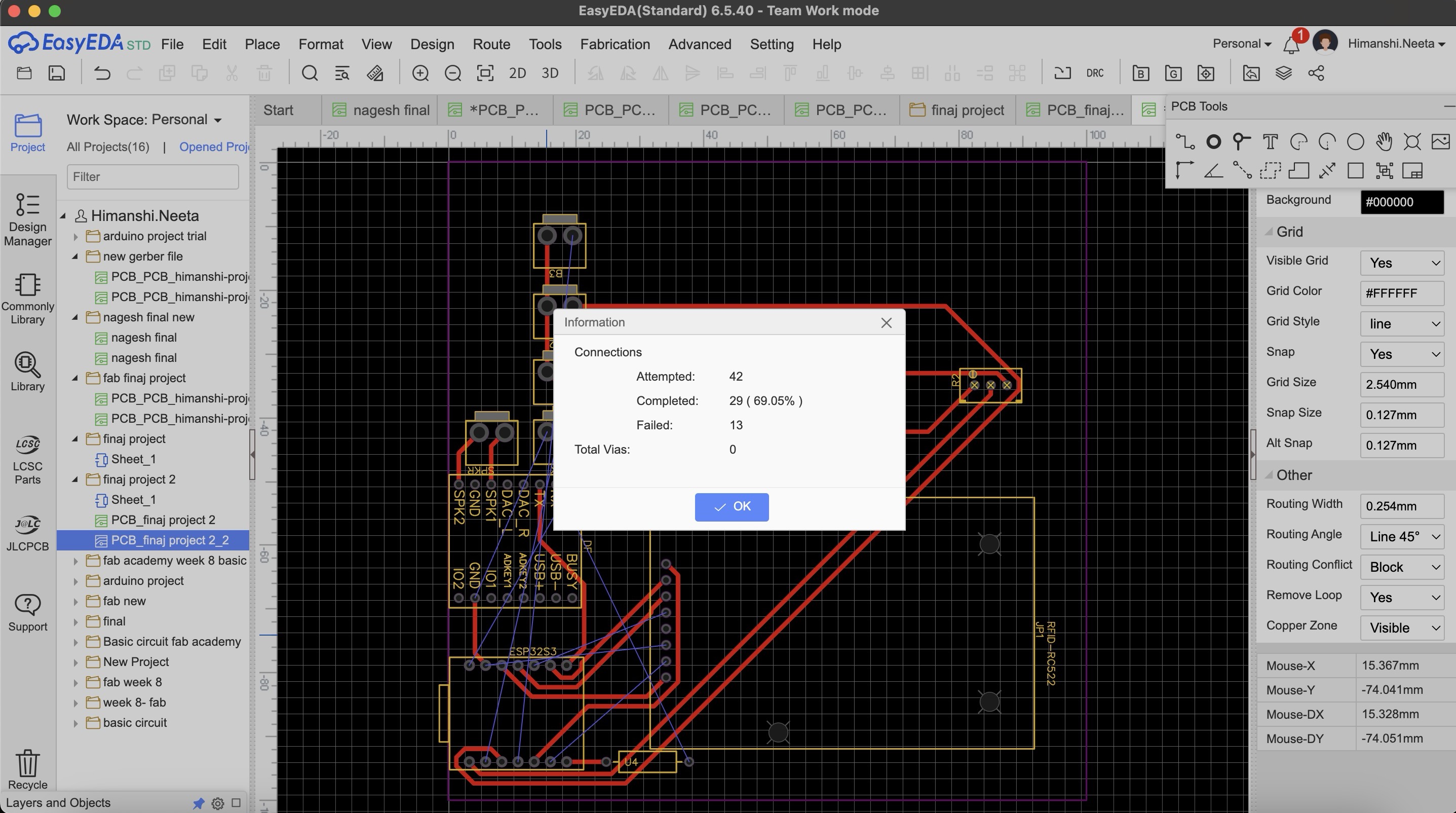
Then I selected the rectangle of 10 by 10cm as we wanted and placed the component how I needed for it to be fit on the case as shown in placing the components parts. I wanted to make a single sided pcb as that is more convinient and easy to use but when I saved my file and did auto routing there were many errors as shown in the image below, the connections were too complicated.
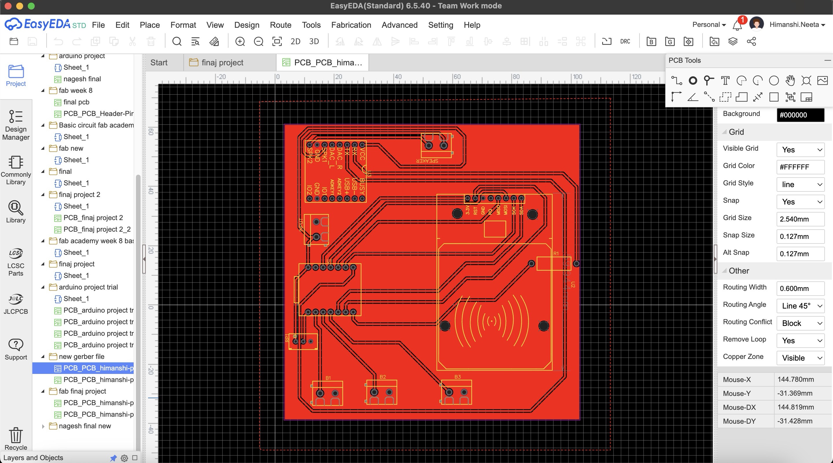
Then I designed double sided pcb and there were no errors.
After designing double sided pcb I realised we don't have the relivent tool for doing double sided pcb so it was not possible for the tools to come as the wait time was long.
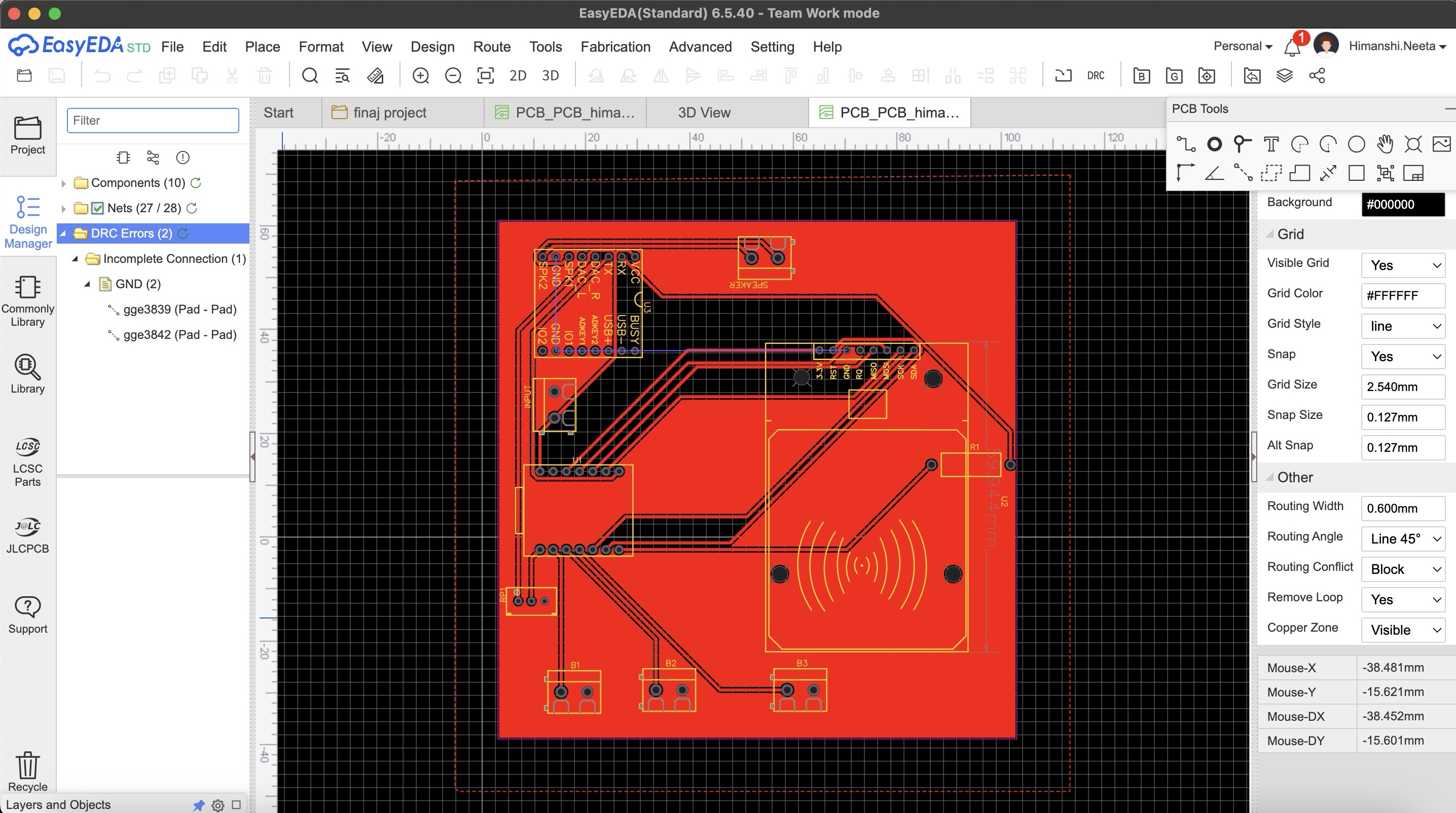
So after this again I did maultiple try and error for single sided pcb and this time I did routing manually as auto routing was failing and then in DRC check there were only 2 errors.
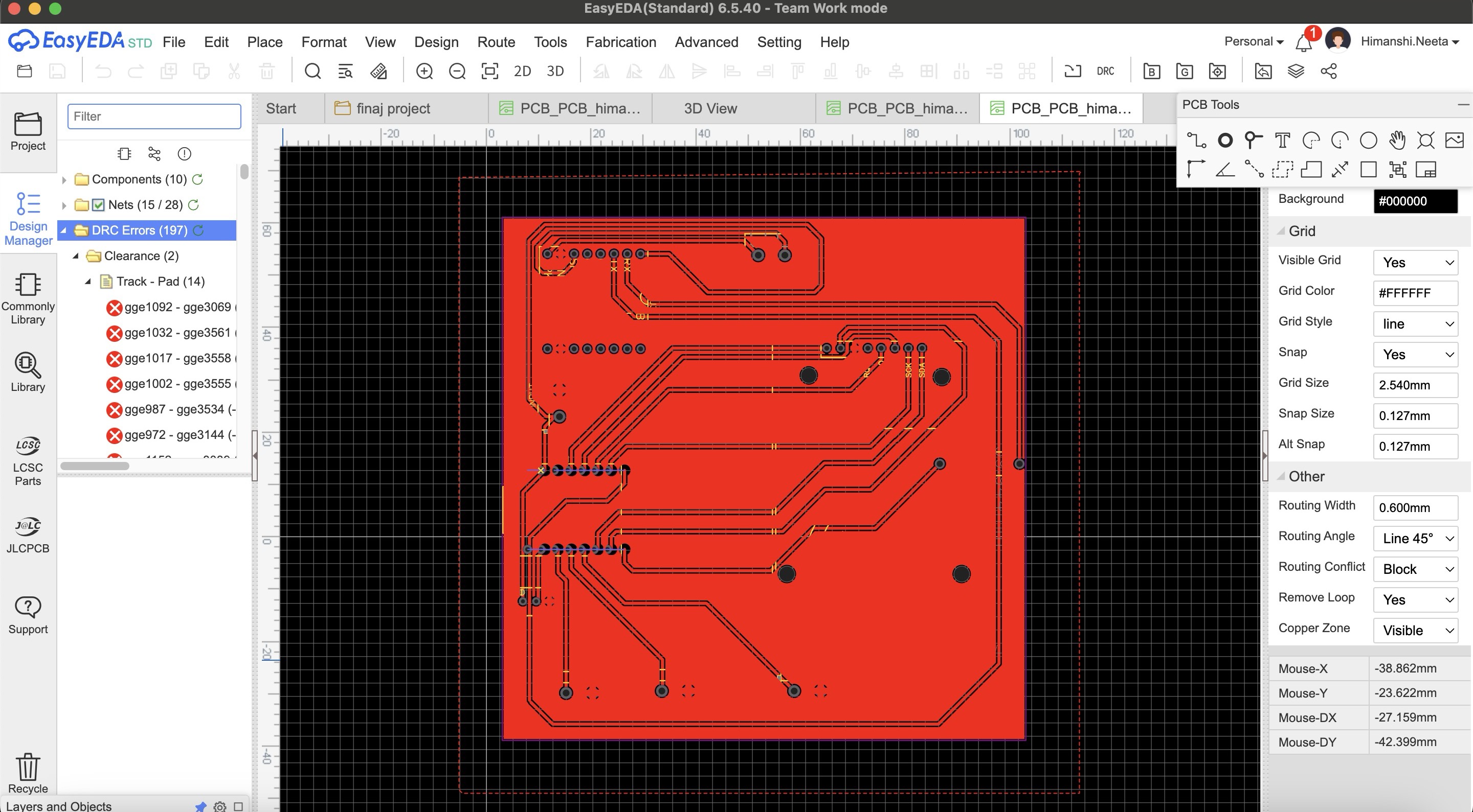
After multiple try and error I got an idea that I'll make common gnd o the entire copper plate, so I designed it accordingly and in the single sided pcb this time again multiple errors as I did auto routing.
Then I again did the routing manually and finally there were no errors and it is looking perfect now.
PCB Milling
After that I started milling this file, I used SRM20 machine and coppercam software. All the steps of how to use machine and software is mentioned in Week 8- Electronic Production.
Hero Shot
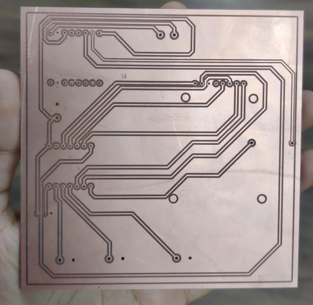
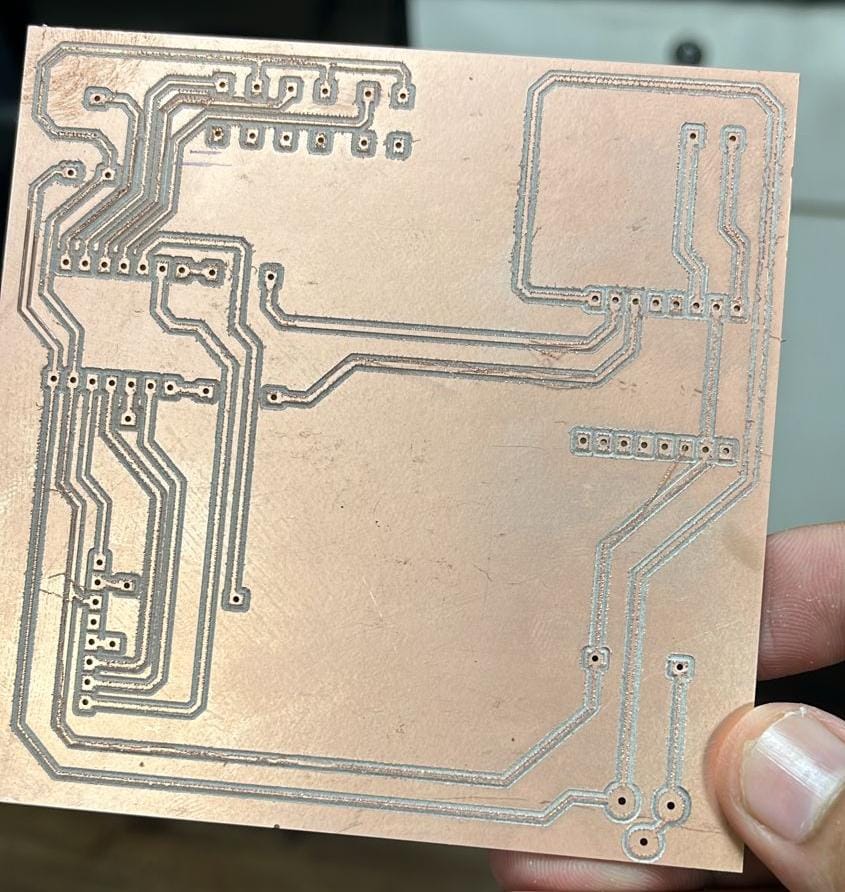
After milling I realised that I should have mirrored the file in copper cam because now the components will be difficult to solder from top, the components should be soldered from below and not from up.
Then I milled a new pcb and in that I mirrored the file
Multimeter testing
After soldering and before soldering too, I tested the connections with the help of multimeter.
Code
What does this code do?
This Arduino code integrates an RFID reader and a DFPlayer Mini MP3 player to create an interactive audio playback system. It uses the MFRC522 RFID module to detect RFID cards and the DFRobotDFPlayerMini library to control the MP3 player. The code initializes the RFID reader and sets up pins for three buttons: start, stop, and pause. When an RFID card is detected, its UID is compared against predefined UIDs stored in an array. If a match is found, the corresponding audio file is played from the MP3 player. The code also reads a potentiometer value to dynamically adjust the volume. Additionally, pressing the start button plays a default audio file, the stop button stops the playback, and the pause button pauses the playback. Debug messages are printed to the serial monitor for monitoring the system's status.
    #include
      #include
      #include

      // RFID RC522 pins
      #define SS_PIN 6
      #define RST_PIN 5

      // Button pins
      #define START_BUTTON_PIN 2
      #define STOP_BUTTON_PIN 3
      #define PAUSE_BUTTON_PIN 4

      MFRC522 mfrc522(SS_PIN, RST_PIN);
      DFRobotDFPlayerMini myDFPlayer;

      // Map RFID card UIDs to sound file numbers
      const byte cardUIDs[10][4] = {
        { 0xE0, 0x14, 0xC6, 0x3B },
        { 0x50, 0x5A, 0x77, 0x59 },
        { 0x43, 0x85, 0x12, 0x50 },
        { 0x93, 0xDB, 0x02, 0xE4 },
        { 0x24, 0xAE, 0xD0, 0x09 },
        { 0xD3, 0xA0, 0x67, 0x1A },
        { 0xD3, 0xA0, 0x67, 0x1A },
        { 0xE3, 0x2B, 0xA2, 0xE4 },
        { 0x43, 0x75, 0xAD, 0xE4 },
        { 0xC3, 0x80, 0x50, 0x1D }
      };

      void setup() {
        Serial.begin(9600);  // Initialize hardware serial for DFPlayer Mini at 9600 baud
        Serial1.begin(9600, SERIAL_8N1, 44, 43);
        SPI.begin();         // Init SPI bus
        mfrc522.PCD_Init();  // Init MFRC522

        pinMode(START_BUTTON_PIN, INPUT_PULLUP);
        pinMode(STOP_BUTTON_PIN, INPUT_PULLUP);
        pinMode(PAUSE_BUTTON_PIN, INPUT_PULLUP);
        pinMode(1,INPUT_PULLUP);
        if (!myDFPlayer.begin(Serial1)) {
          Serial.println(F("Unable to begin:"));
          Serial.println(F("1.Please recheck the connection!"));
          Serial.println(F("2.Please insert the SD card!"));
          while (true)
            ;
        }
        myDFPlayer.volume(30);  // Set volume value (0~30).

        Serial.println(F("Place your RFID card near the reader..."));
      }

      void loop() {
        int potValue = analogRead(1);

        int vol = map(potValue, 0, 4096, 0, 30);
        vol = constrain(vol,0,30);
        myDFPlayer.volume(vol);
        Serial.println("Volume: "+String(vol));
        Serial.println("Button Start: " + String(digitalRead(START_BUTTON_PIN)));
        Serial.println("Button Stop: " + String(digitalRead(STOP_BUTTON_PIN)));
        Serial.println("Button Pause: " + String(digitalRead(PAUSE_BUTTON_PIN)));
        // Check for button presses
        if (digitalRead(START_BUTTON_PIN) == LOW) {
          myDFPlayer.play(1);  // Play a default audio file (e.g., 0001.mp3)
          Serial.println("Start button pressed, playing default audio.");
          delay(300);  // Debounce delay
        }

        if (digitalRead(STOP_BUTTON_PIN) == LOW) {
          myDFPlayer.stop();
          Serial.println("Stop button pressed, stopping audio.");
          delay(300);  // Debounce delay
        }

        if (digitalRead(PAUSE_BUTTON_PIN) == LOW) {
          myDFPlayer.pause();
          Serial.println("Pause button pressed, pausing audio.");
          delay(300);  // Debounce delay
        }

        // RFID code
        if (mfrc522.PICC_IsNewCardPresent() && mfrc522.PICC_ReadCardSerial()) {
          // Print Card UID in the desired format
          Serial.print("{");
          for (byte i = 0; i < mfrc522.uid.size; i++) {
            Serial.print("0x");
            Serial.print(mfrc522.uid.uidByte[i], HEX);
            if (i < mfrc522.uid.size - 1) {
              Serial.print(", ");
            }
          }
          Serial.println("}");

          // Compare the read UID with the predefined UIDs
          for (int i = 0; i < 10; i++) {
            if (memcmp(mfrc522.uid.uidByte, cardUIDs[i], 4) == 0) {
              Serial.print("Playing sound for card ");
              Serial.println(i + 1);
              myDFPlayer.play(i + 1);  // Play the corresponding MP3 file (files should be named 0001.mp3, 0002.mp3, etc.)
              break;
            }
          }

          delay(1000);
        }
        delay(100);
      }
HeroShot of PCB
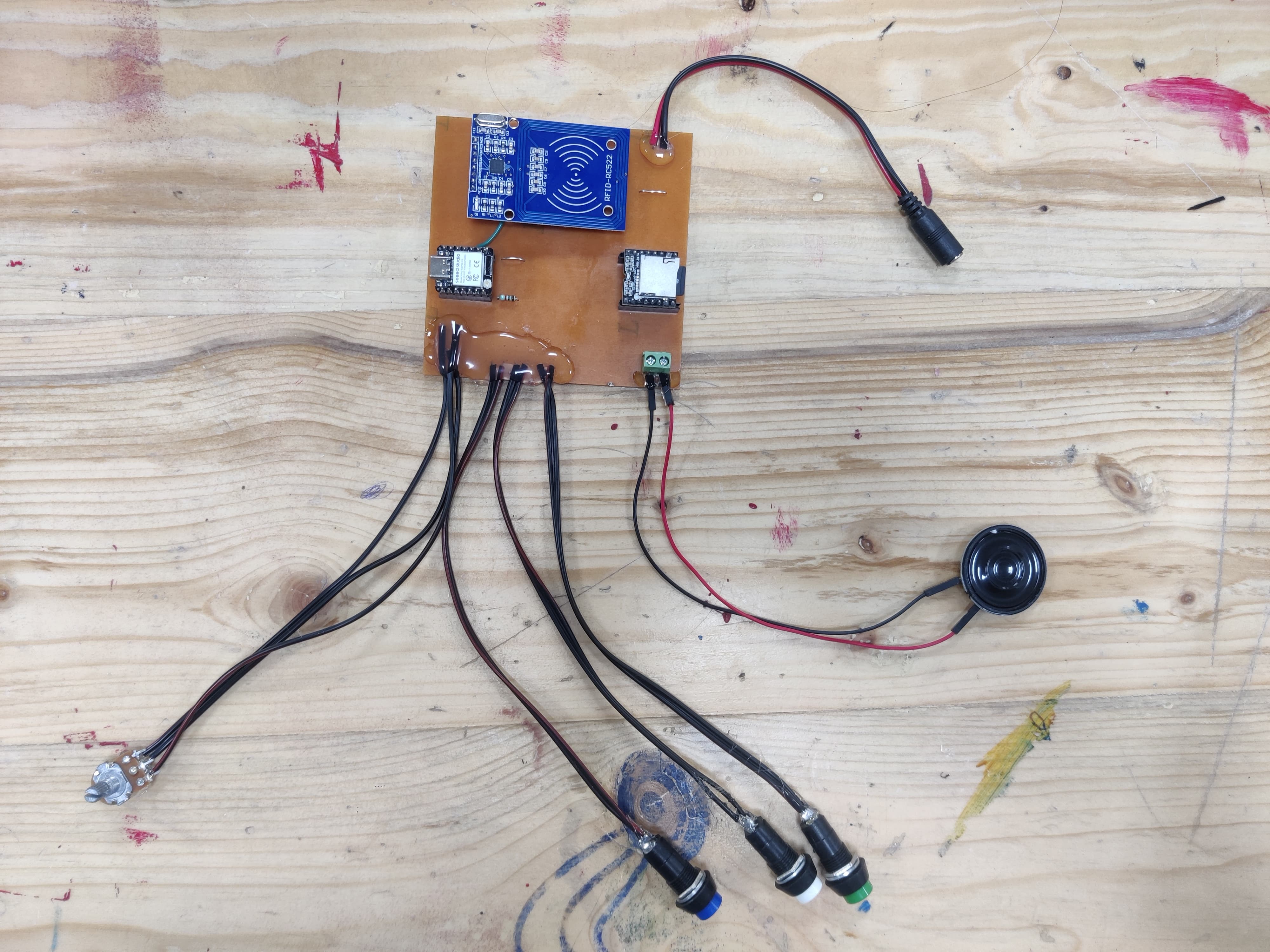
WOrking of PCB
After that I made the design for pcb and milled it and tried out the circuit on that.
Conclusion from this week
This week provided valuable insights into the practical application of input devices in microcontroller systems. The group assignment on sound sensors and the individual project with the ultrasonic sensor and RP2040 highlighted the importance of integrating and correctly interpreting sensor data to control outputs, such as the blinking LED. Overall, the assignments reinforced my understanding of sensor integration, signal processing, and real-time data analysis, which are crucial skills in developing interactive and responsive electronic systems.
Download Design files
Code fileImage Credits
All images of cover page are credited below:
https://images.app.goo.gl/cAHPtXbUWLjaHkoE9
https://images.app.goo.gl/F29zJF5vR8inebTU6
https://images.app.goo.gl/jhqycNgqxsWtNhVC8
https://images.app.goo.gl/C1dUqDX5g1zfnyyH8
https://images.app.goo.gl/Ar7PYLBVZ8rFXC6c7
https://images.app.goo.gl/dJeNh3UUsm7YF7gm8
https://images.app.goo.gl/C7zvZmSBhc4fJgo4A
https://images.app.goo.gl/B5qPojSXupcgeqVJ6
https://images.app.goo.gl/iVn91KiKtMuy2tkk9