Final Project
Slide
Presentation video
Old Video
New video
To know in detail about
system integration Click here
Application and Integrations Click here
Invention, Intellectual Property, and Income
Click here
Inspiration and Idea
As a designer, my inspiration for creating this game came from a recent visit to a blind school where I observed that while the kids were incredibly smart and proficient in languages, they were not learning the basics effectively. At the same time, I noticed in my own building that small children were spending a lot of time on YouTube, with parents using the platform to teach them animals, fruits, and colors. This contrasted sharply with my own childhood, where we learned these basics from boring textbooks.
I realized that there was a need to make learning more engaging and fun, moving away from both the overuse of smartphones and the traditional, unengaging methods of textbooks. I thought, why not create a game that makes learning interactive and enjoyable? Thus, I developed "The Jungle Puzzle Quest" to provide an educational experience that is both fun and effective, without relying on smartphones or dull textbooks. This game aims to capture the curiosity of children and make the learning process exciting and accessible for all.
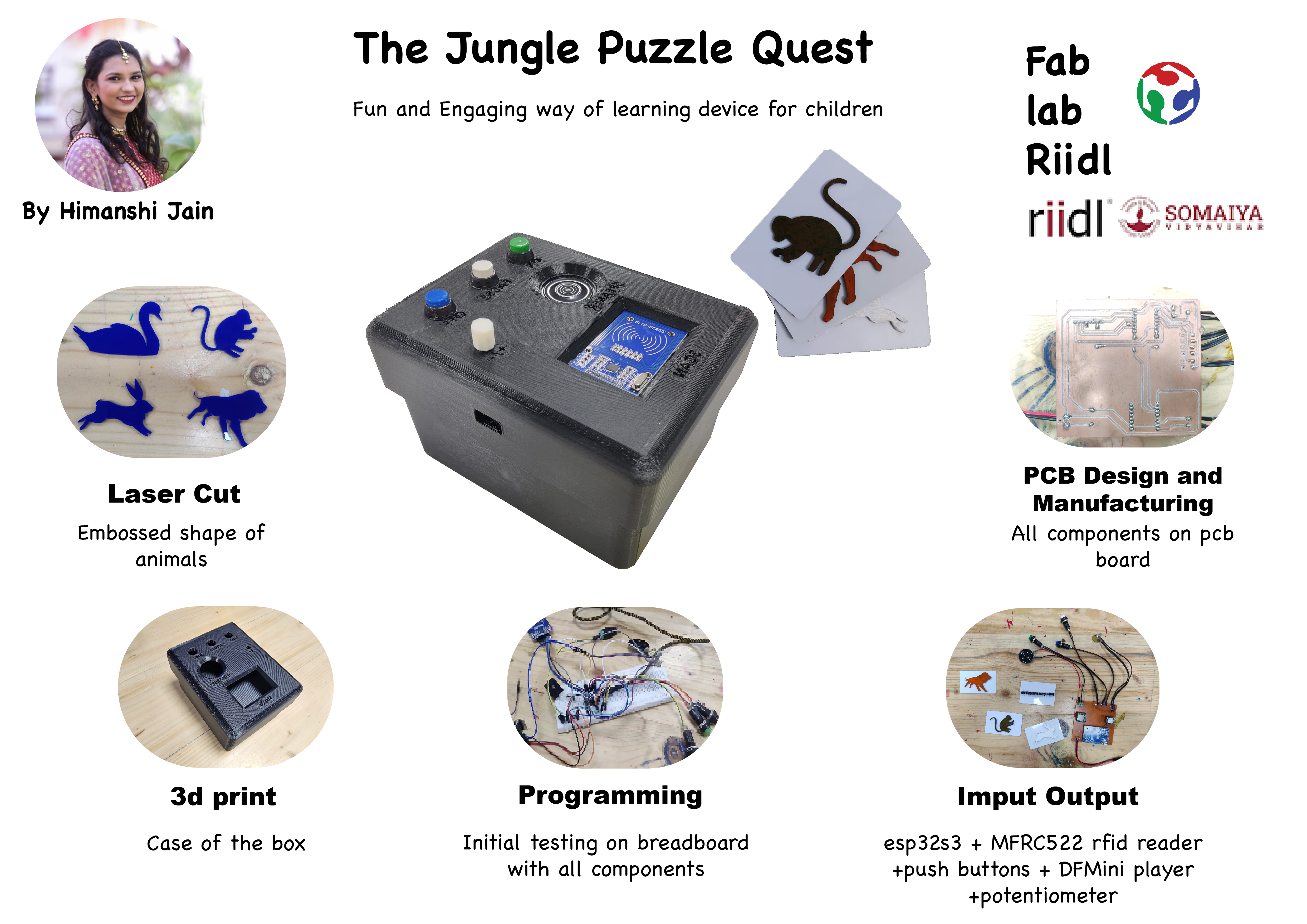
Name of the game- "The Jungle Puzzle Quest"
Storyline:
Once upon a time, in a lush jungle far, far away, there lived a curious child named Alex. Eager to explore the secrets of the jungle, Alex embarked on an exciting adventure. Equipped with nothing but courage and a sense of wonder, Alex stepped into the dense foliage, ready to encounter the majestic creatures that called the jungle their home.
As Alex journeyed deeper into the heart of the jungle, the sounds of chirping birds and rustling leaves filled the air. Suddenly, a mischievous monkey swung down from the trees, its playful chatter drawing Alex's attention. The friendly monkey, named Milo, greeted Alex and offered to be their guide through the jungle.
Excited to learn more about the jungle's inhabitants, Alex followed Milo's lead. Along the way, they encountered a wise old rabbit named Rosie, who shared fascinating tales of the forest. Rosie, sensing Alex's eagerness to learn, directed them to a mystical pond where a graceful swan named Sera glided serenely.
With each encounter, Alex's knowledge of the jungle grew, and they discovered the unique traits and sounds of each animal they met. Guided by Milo, Rosie, and Sera, Alex's adventure led them closer to their ultimate goal: finding the king of the jungle, the mighty lion.
As the sun began to set, casting golden hues over the canopy, Alex and their newfound friends reached the edge of the jungle, where the lion's roar echoed in the distance. With hearts pounding with excitement, they knew that the final challenge awaited them - to unlock the secrets of the lion's domain and complete their animal adventure.
And so, with Milo, Rosie, and Sera by their side, Alex prepared to solve the ultimate puzzle and prove themselves worthy of meeting the king of the jungle, the majestic lion.
Objective:
In this electronic card game, designed for both partially sighted and sighted players, the main aim is to introduce children to various animals, their sounds, and characteristics, fostering learning through auditory and tactile experiences, all without the need for screens or phones.
How to play the game
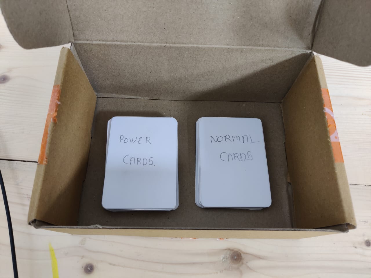
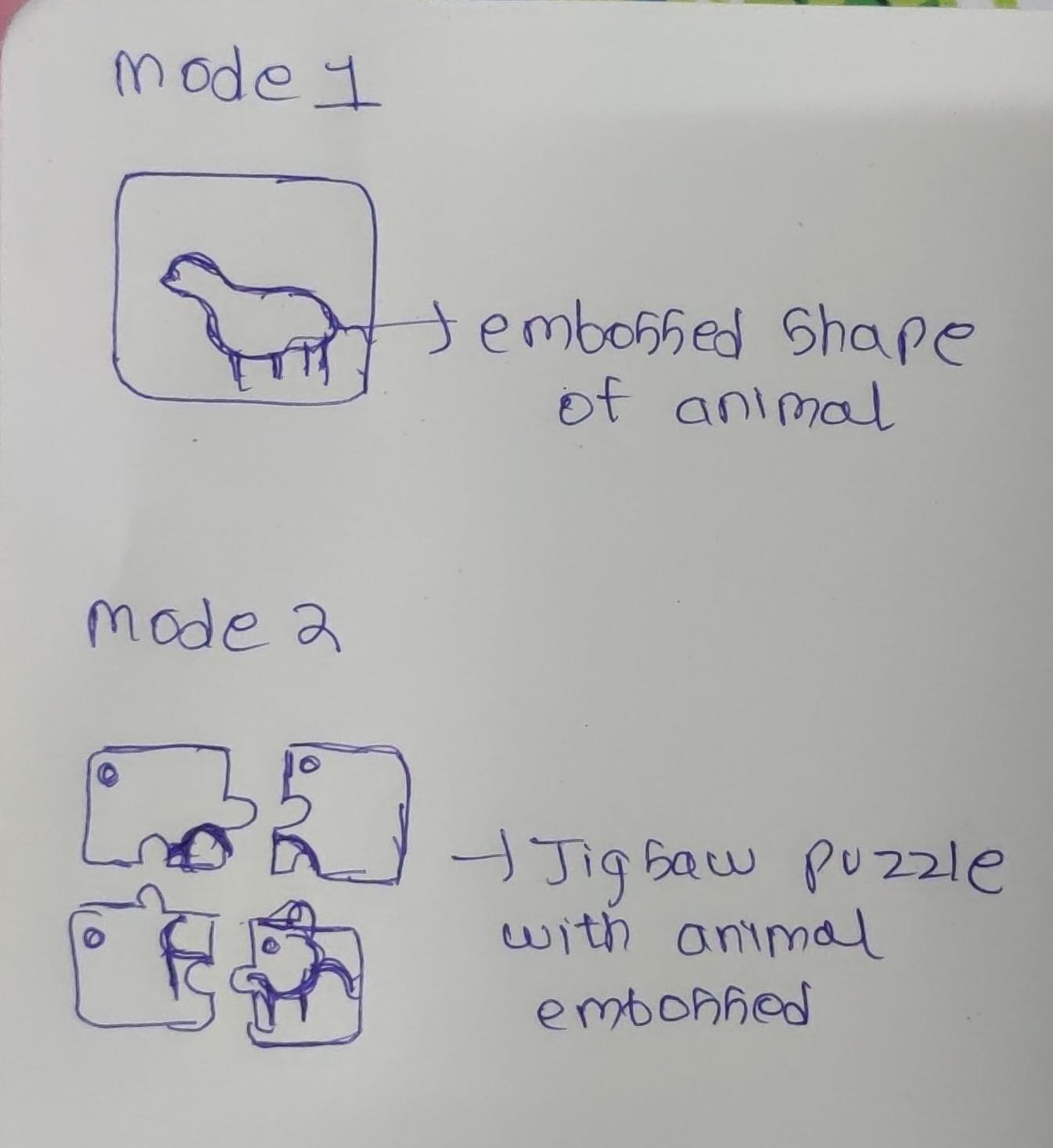
There are two decks of cards. One deck features animals embossed on each card, one animal per card. The other deck contains puzzle cards, with each animal represented by four jigsaw puzzle pieces. To distinguish between animals, each puzzle card bears a symbol, such as a circle for elephants, as specified in the rule book.
In Mode 1, players select a card from the first deck featuring the full animal. By feeling the embossed card, players engage their tactile senses. After selecting a card, they scan it using the RFID reader atop the box. Upon scanning, the game emits a sound describing the animal's features, unique traits, and its sound. Through this mode, players can learn about numerous animals by feeling and scanning different cards.
In Mode 2, players apply their newfound knowledge in a hands-on activity - solving jigsaw puzzles. Upon selecting Mode 2, a prompt instructs players to assemble a specific animal puzzle, like an elephant. Players refer to the rule book to identify the symbol associated with the animal (e.g., a circle for elephants). Then, they locate and remove the four puzzle cards corresponding to that symbol from the deck. By fitting the puzzle pieces together, players reinforce their understanding of the animal's shape learned in Mode 1. After assembling the puzzle, players scan all four cards together. If correct, the game unlocks the next level, prompting players to assemble the puzzle of the next animal in line.
This engaging game structure ensures an enjoyable and educational experience for players of all abilities, encouraging interaction with animals in a fun and inclusive manner.
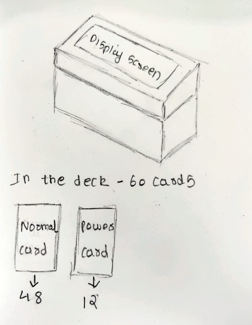
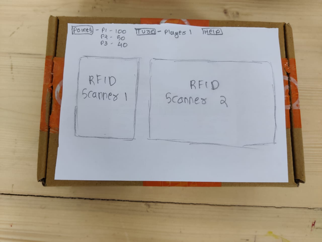
Basic Prototyping
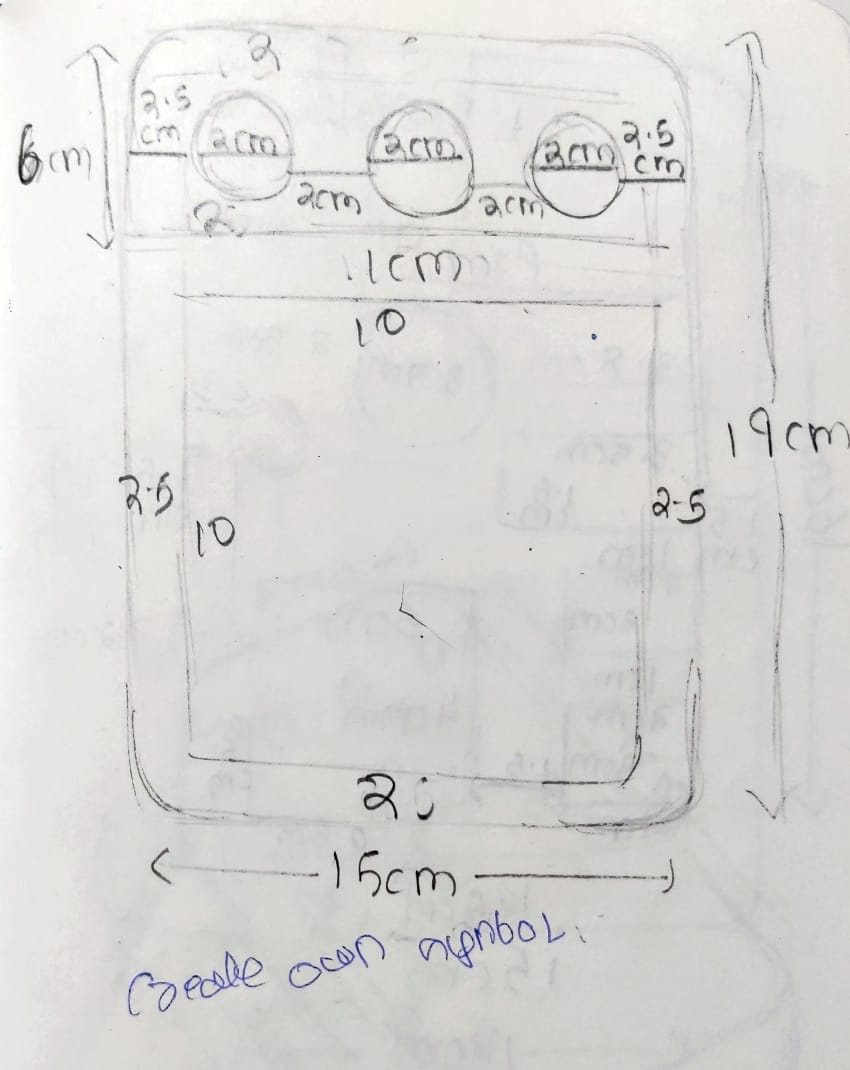
Initial idea of how my box will look and where will be the placement of cards and scanner also how will the cards be looked.
Components
Below are the list of components which I used in my project.
1. Microcontroller/SBC:
- Esp32s3 seed studio xiao
3. Input Devices:
-Push buttons
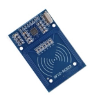
4. Card Reader MFRc522 RFID Module with cards:
- MFRC522 RFID Reader and Cards
5. Speaker:
- small speaker module
6. Power Supply:
- Type C USB for esp32s3, power bank, DC jack for external power if needed
7. Enclosure/Casing:
- 3D printed case
8. Wiring and Connectors:
- Jumper wires, male/female headers, soldering iron
9. Programming Software/IDE:
- Arduino IDE
11. Graphics and Design Software:
- Adobe Illustrator, Fusion 360
Part 1- Electronics
How to use the MFRC522 RFID reader.
To start with the basics and get used to the components i started with basics of hoe rfid works, I read about it and connected with basic arduino to try it.
What is RFID ?
RFID means radio-frequency identification. RFID uses electromagnetic fields to transfer data over short distances. RFID is useful to identify people, to make transactions, etc…
You can use an RFID system to open a door. For example, only the person with the right information on his card is allowed to enter. An RFID system uses:
1. Tags
Attached to the object to be identified, in this example we have a keychain and an electromagnetic card. Each tag has his own identification (UID).

2. Two-way radio transmitter-receiver,
The reader, that send a signal to the tag and read its response.
Specifications
1.Input voltage: 3.3V
2. Price: approximately 3$
3. Frequency: 13.56MHz
Library download
Here’s the library you need for this project:
1. Download the RFID library here created by miguelbalboa
2. Unzip the RFID library
3. Install the RFID library in your Arduino IDE
4. Restart your Arduino IDE
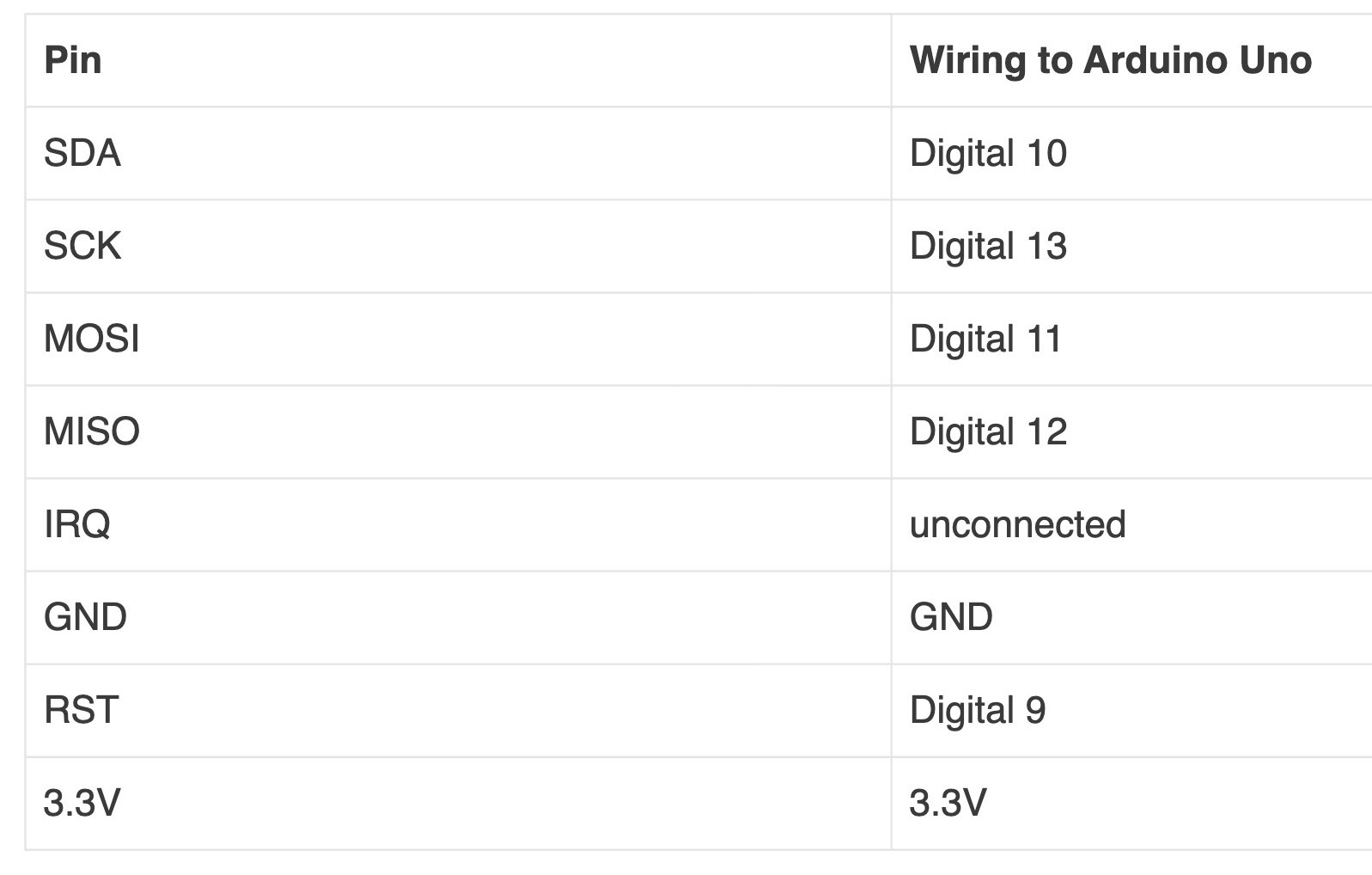
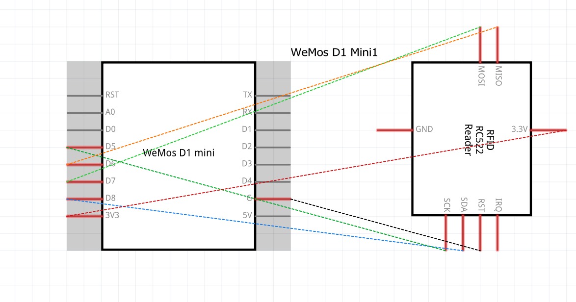
Pin wiring
This is the basic connections of how to connect rfid reader with ay micro controller.
Caution:
You must power this device to 3.3V!
Circuit
Below is the basic circuit of rfid reader, to get start with rfid I first made the basic connections looking at the circuit diagram.
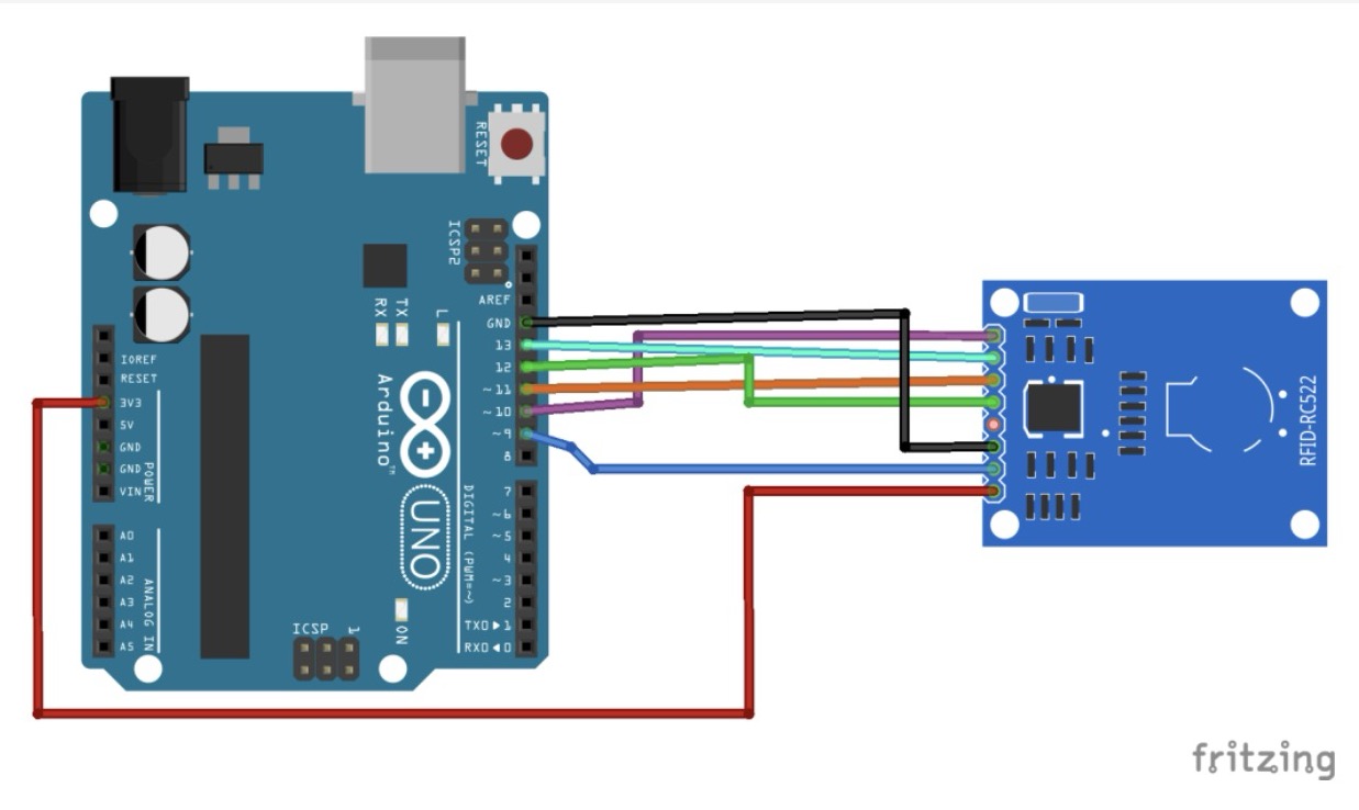
Connections
I made the connections by looking at the circuit diagram in the above image.
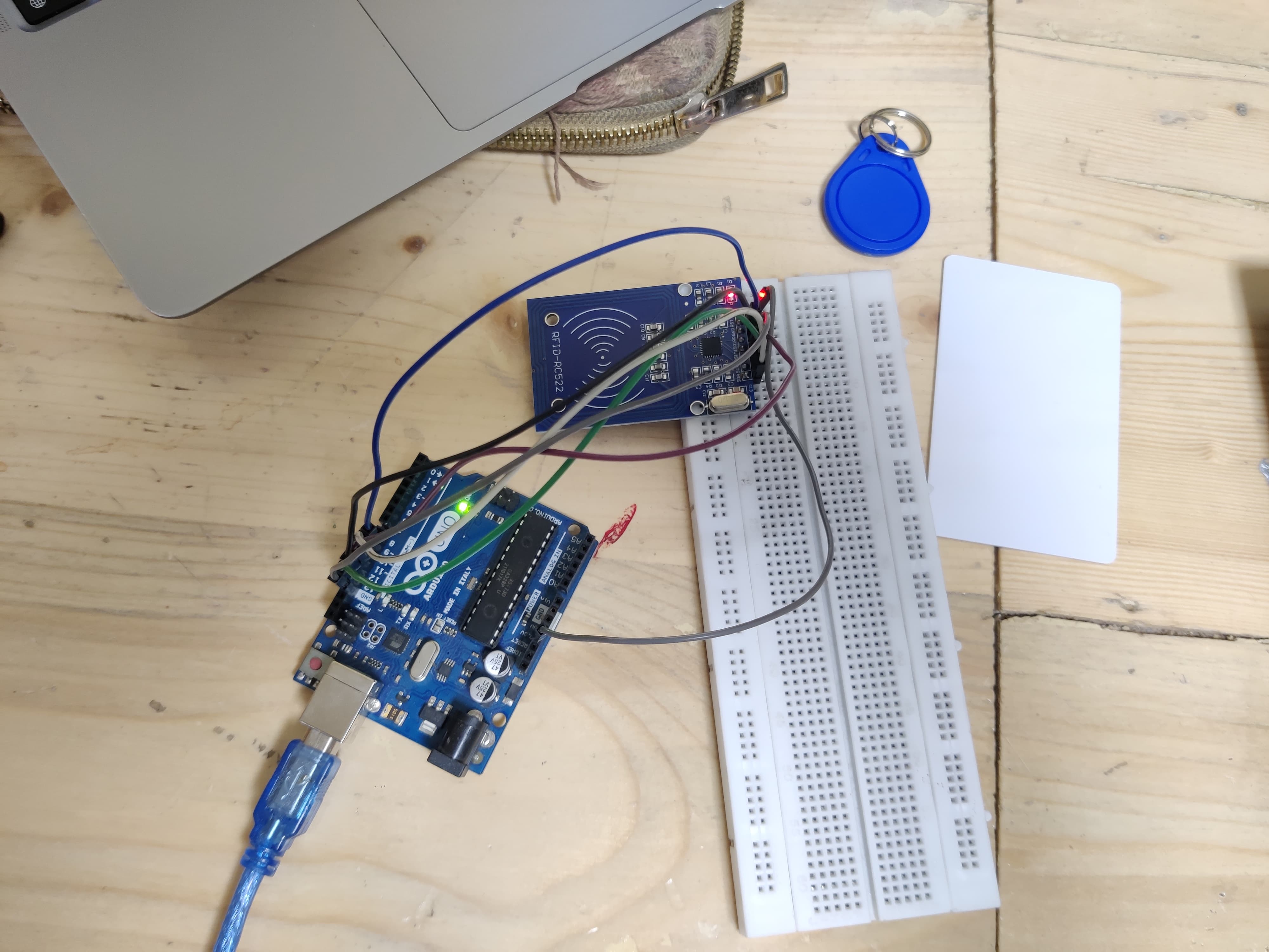
Initial testing
After making the basic connection from the circuit diagram I did the initial testing of how the rfid cards and kitchen is read by the reader.
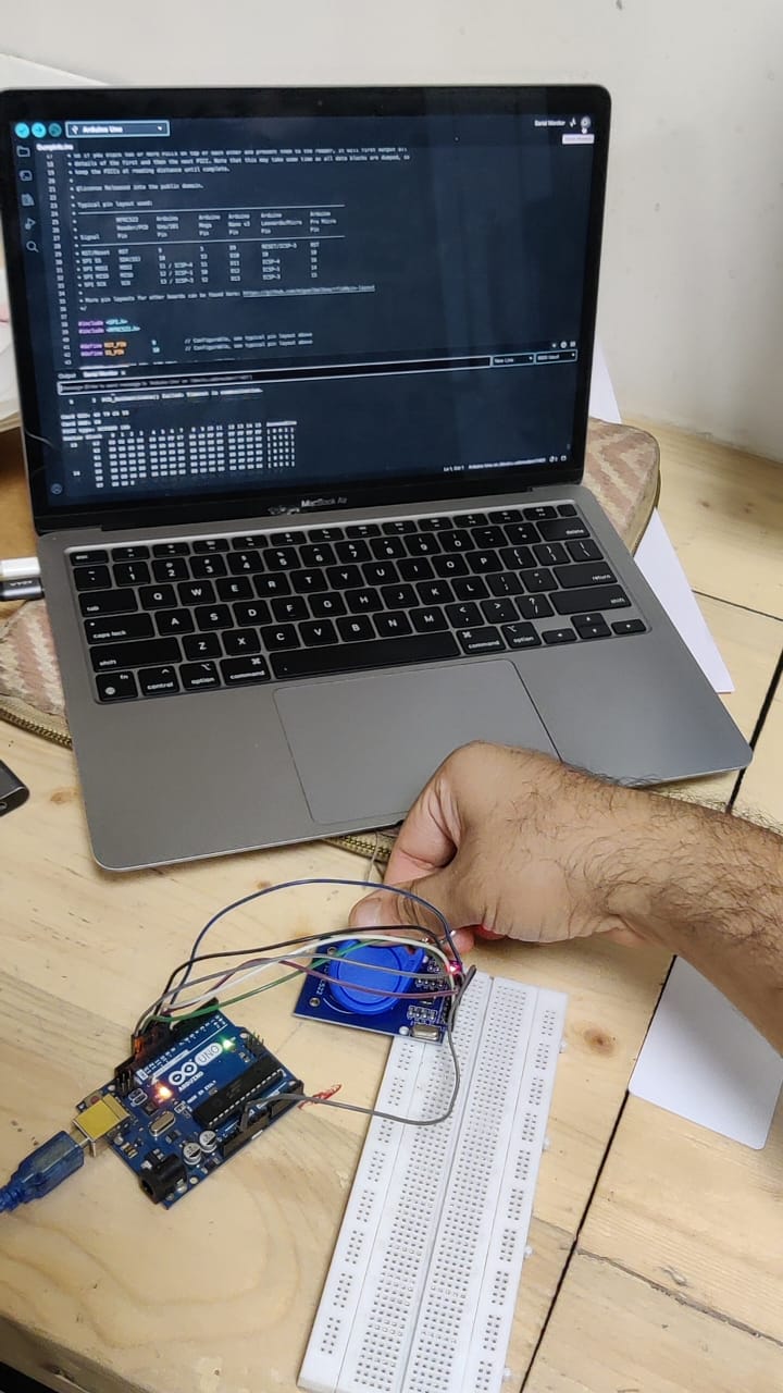
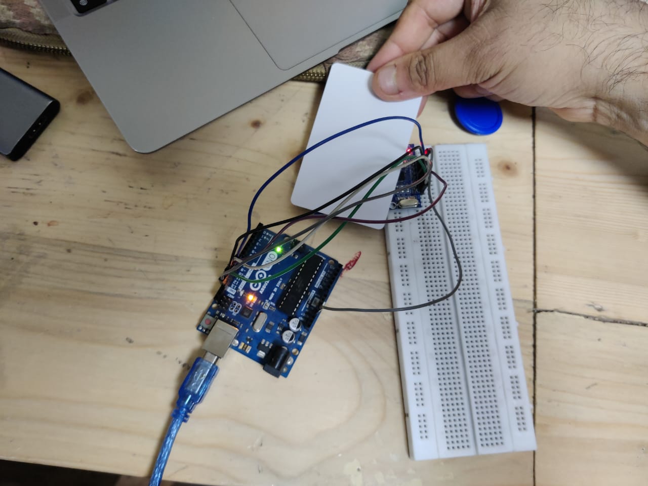
Checking thickness
As I want to emboss on the surface I wanted to see how much thickness layer we can add above and below the raeder, so I tested with 3mm and it was successful and after that I understood that 2cm is the distance from which rfid reader can read the card.
How to connect dfMini Player with RC522 RFID reader.
After learning how rfid works on it's own and along with sound then I learned how to connect dfMini Player with rc522 rfid reader.
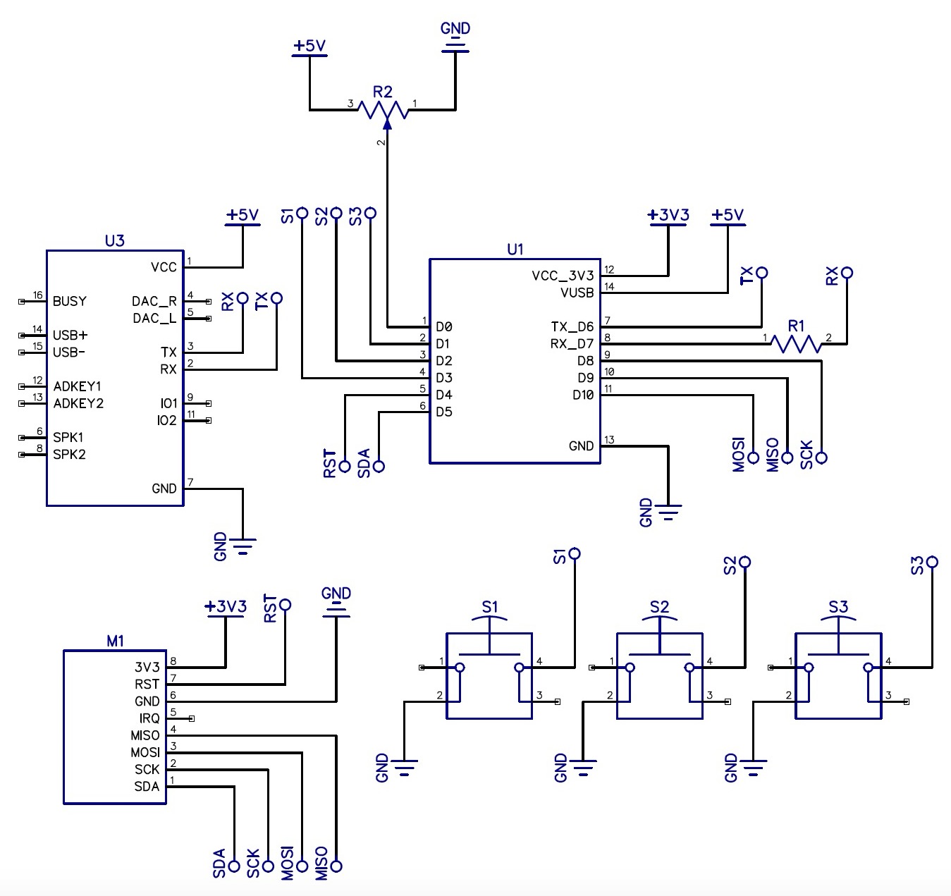
Circuit Diagram
After these I made a crcuit diagram on Tinkercad to understand the connections more better along with the code and made the changes in code as well.
Error
After making this when I showed it to my mentors they identified the error that i used esp32 devboard which was not allowed, we were suppossed to use a chip.
Ideation and solution
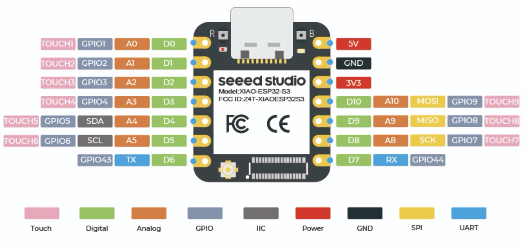
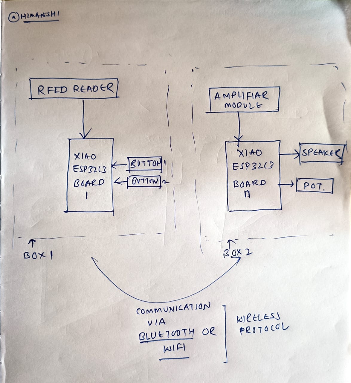
Then looking at this connections I realised that I had used 10 digital pin, 1gnd and 1- 3v3. So in esp32s3 seed studio xiao there are only 11 digital pins also in that it includes 6 analog pins along with rx, tx and other things as showed inthe image below, so I was thinking how will everything will fit in that small chip so I ideated that I can use 2 esp32s3 seed studio xiao chip and connect it via wifi so from in 1 chip there will only be reader and in other chip there will be speaker, dfmini player, potentiometer and push buttons.
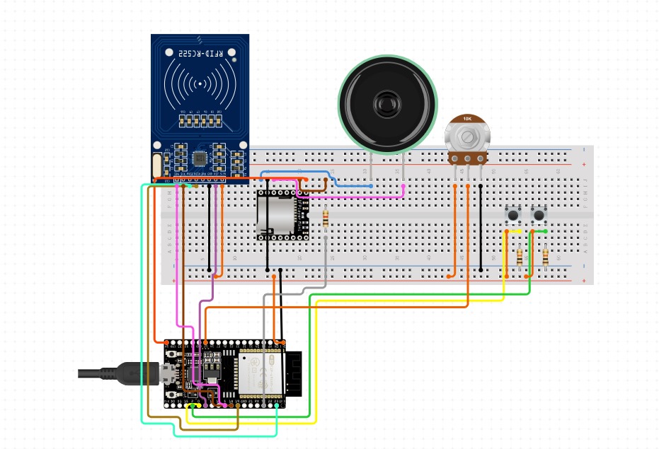
Initially I was getting very confused as both micro controller were different and I need to make the changes in the code as well, so for timming to be more sure I used the same esp32 dev board and made the connections on breadboard like how I was going to do in esp32s3 seed studio xiao chip wirelessly.
So now in 1 esp32 there is only rfid reader and in the other esp32 there are speaker, dfmini player, push buttons and potentiometer.
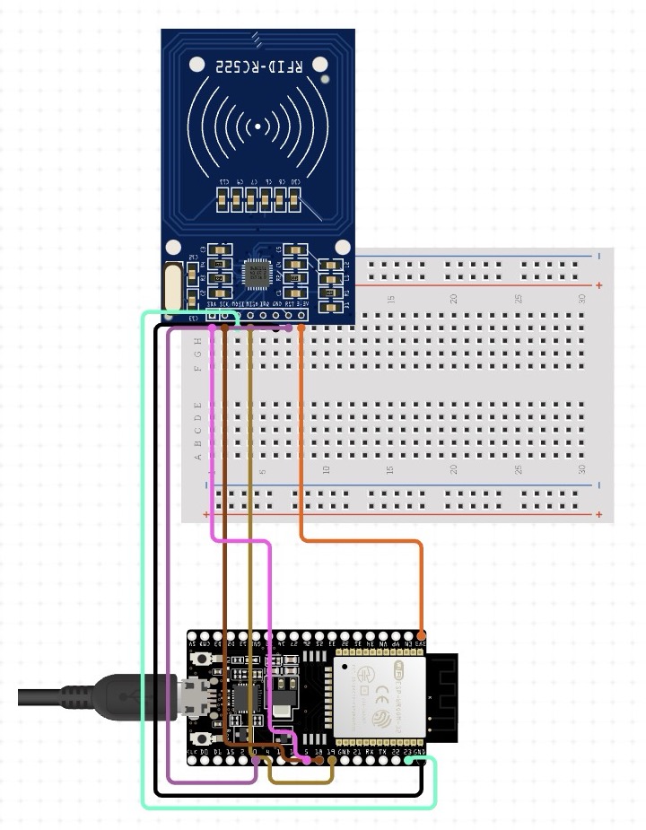
Connections with esp32s3 seed studio xiao
Before starting again I made the connections on easyeda as esp32s3 was not there in tinkercad, to see how to use easy eda in detail you can check Week 8- Electronics design..This time i was more clear about the connections and while making the connections again I realised it can fit in 1 esp32s3 seed studio xiao and there is no need of 2 seperate esp32s3.
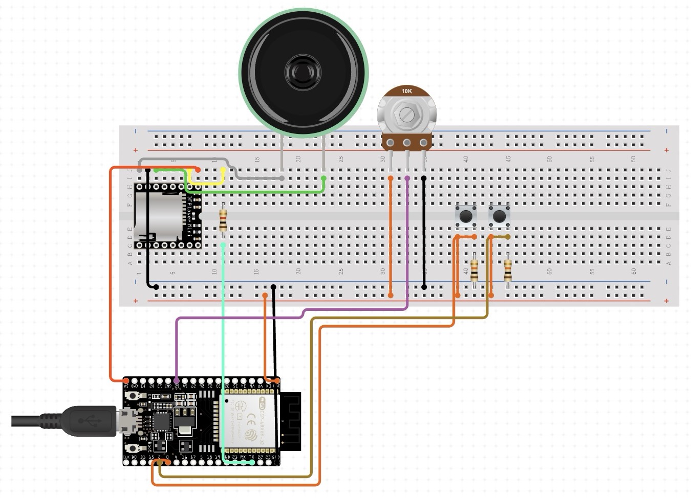
Testing electronics on breadboard
Looking at the connections I made the same connections on breadboard as it is easy to do try and errors in breadboard.
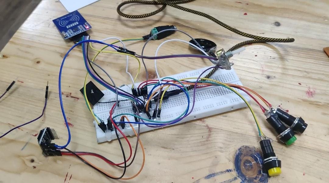
Errors while testing the breadboard
After making the basic connection it was not working and dfmini player was getting too hot and in the serial monitor everything was printing except dfmini player so I added an external power source with the help of dc jack and then it started working and it was not getting that hot.
Breadboard Testing Results
Video 1 shows how the push buttons work
Video 2 shows how rfid works.
Heroshot of working of pcb
Placements of components in pcb
After the breadboard testing working successfully the next step was to design pcb but before that I need to understand where each and every components will be placed in the 3d printed case so that the pcb is designed according to the components placement.
Casing
I had in mind that I'll need to fit at least 20 cards in the lower box so according to that per card with embossed layer was going upto 8-9mm, so I made the total height of the box 10cm.
For the case I am making a cartoon type box where my push button is acting as eyes, potentiometer as nose, rfid reader as mouth, it will be a 3d printed case, only this much was the initial idea which I had. Below are the images of how I styarted with basic sketc and ideating on it.
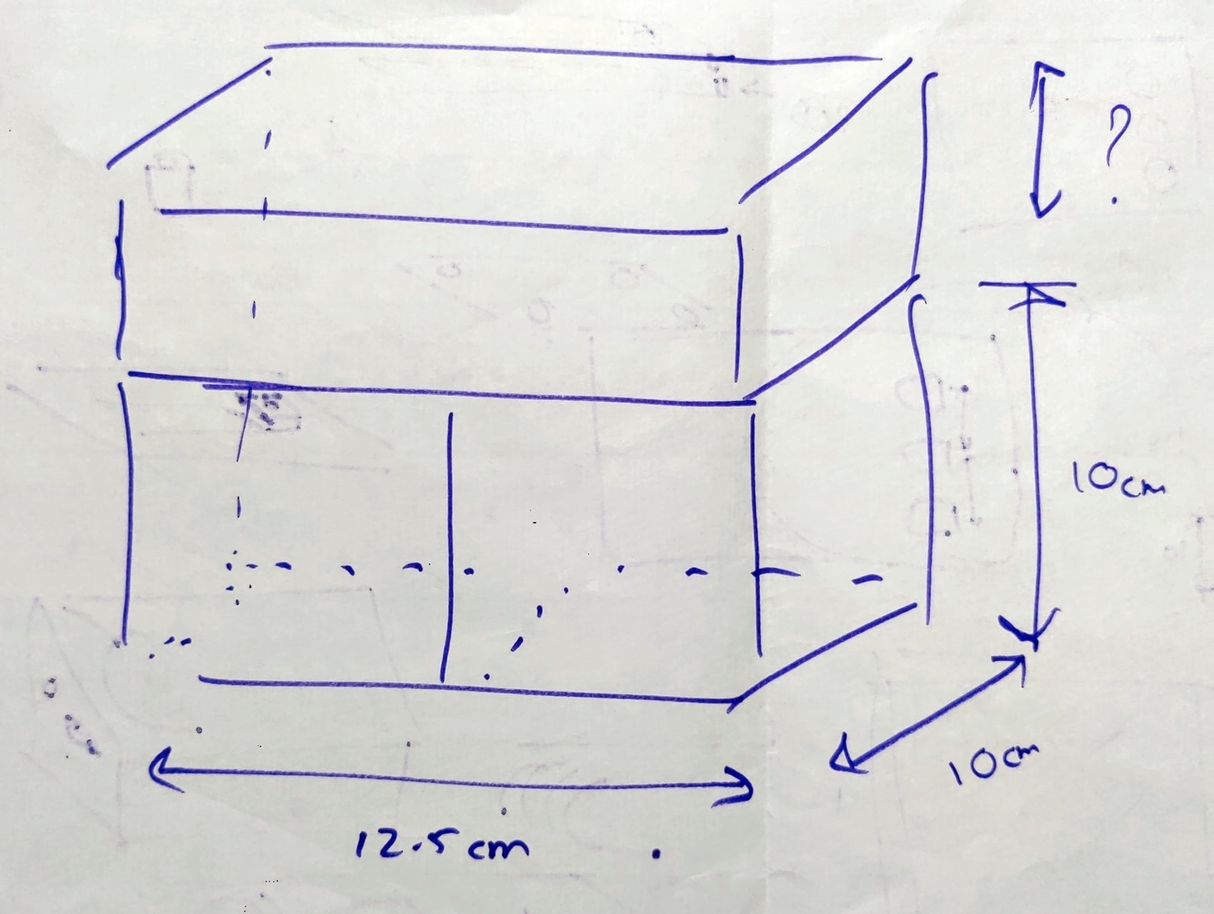
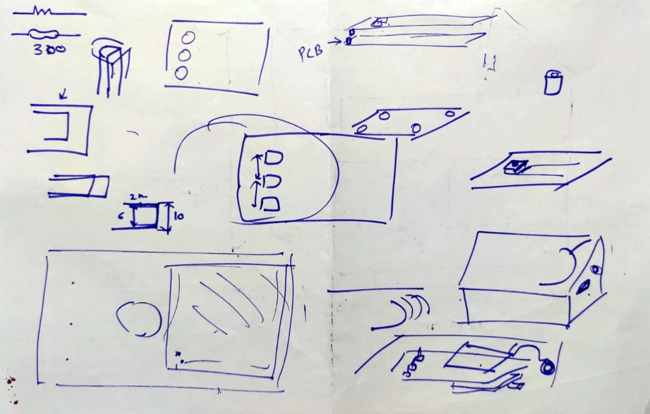
Then I started with placing basic components on paper first and actually understanding where will the components fit in 10 by 10cm box.
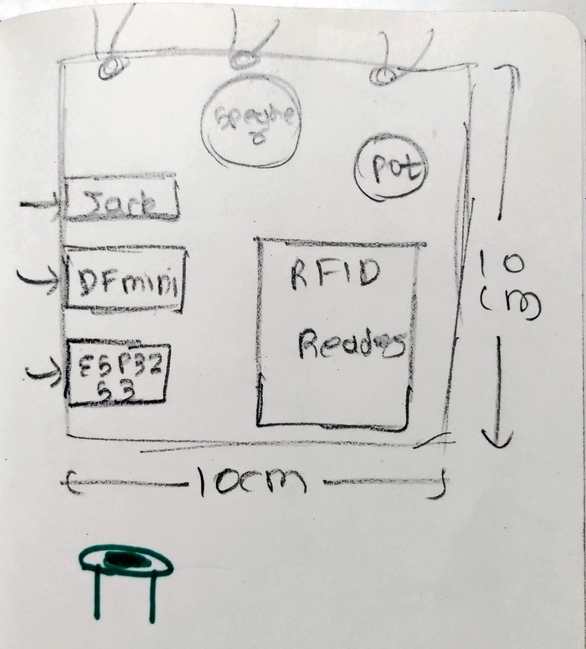
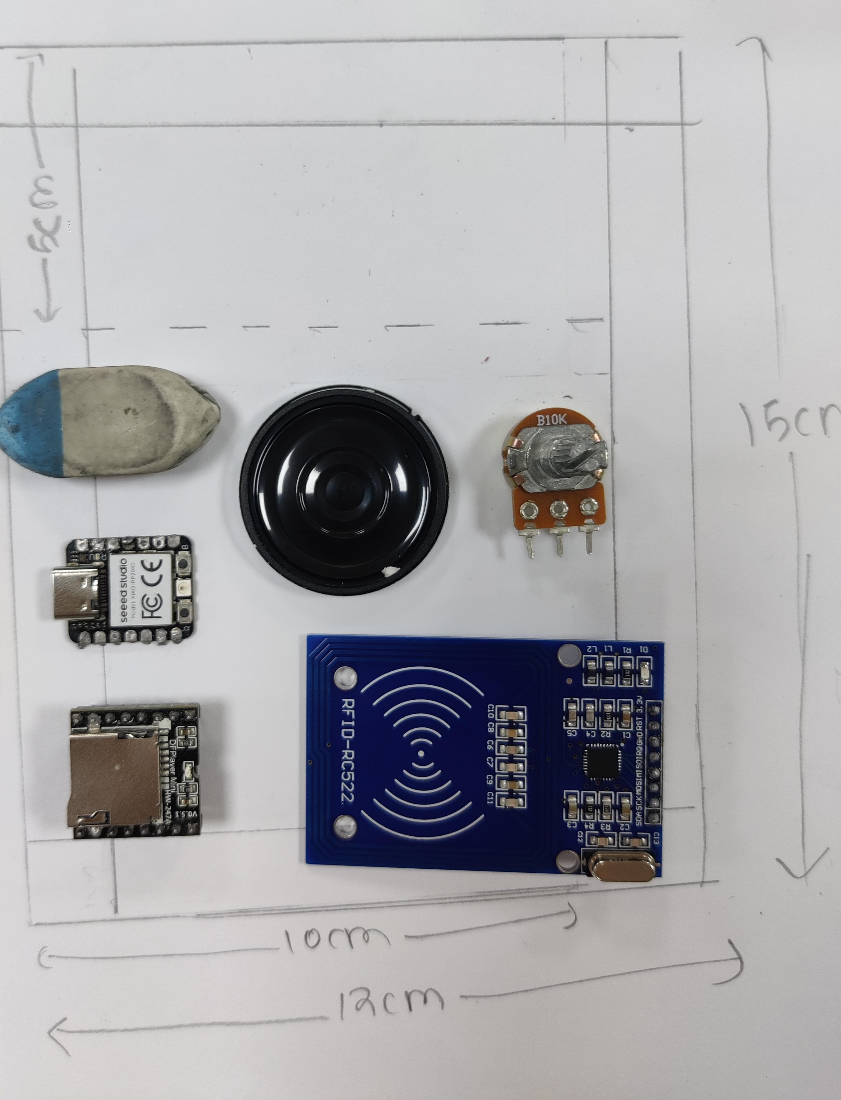
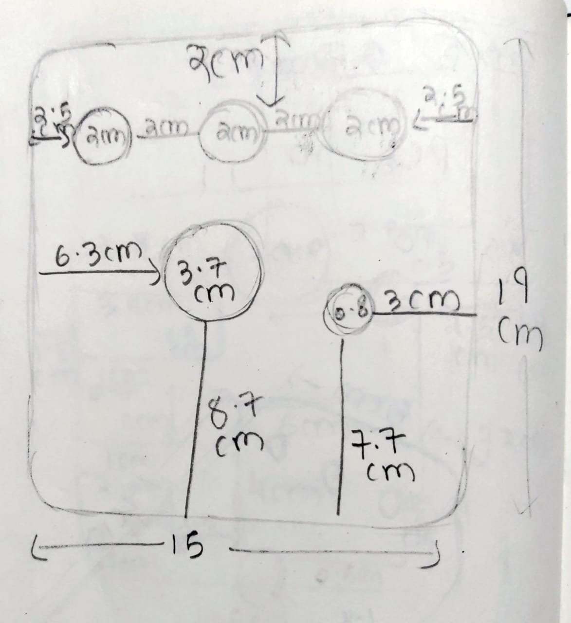
Then I started doing more detailing of each and every component with each other as well as from the border of pcb.
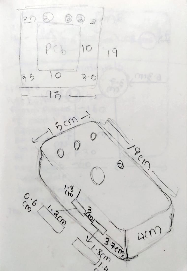
After this I realised I forgot to add a box of pcb holder, how will the pcb fit on the box and doesn't comes to the lower case. I added snap fit joints on the box so that one can even remove and replace the components if needed.
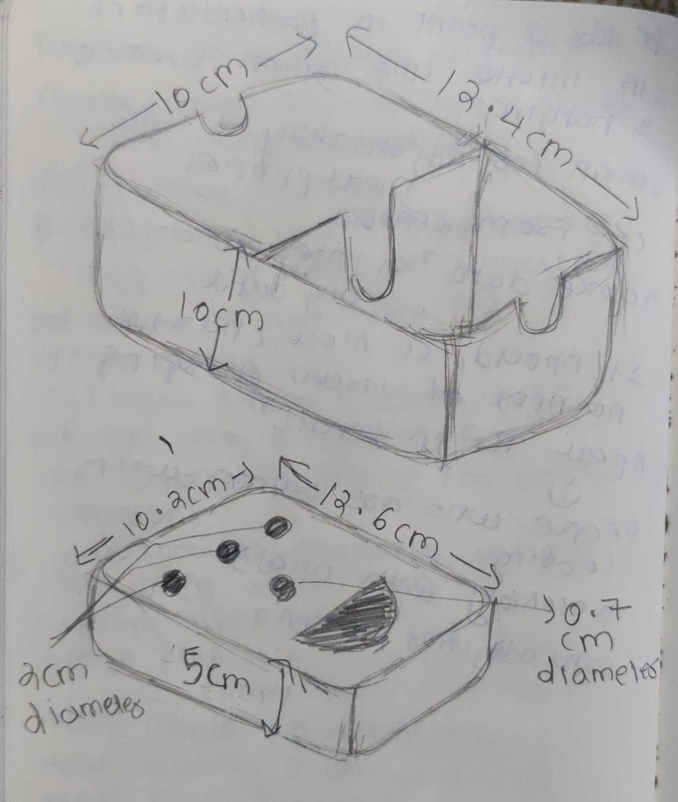
Then I started doing basic 3d on fusion by placing those components in the box.
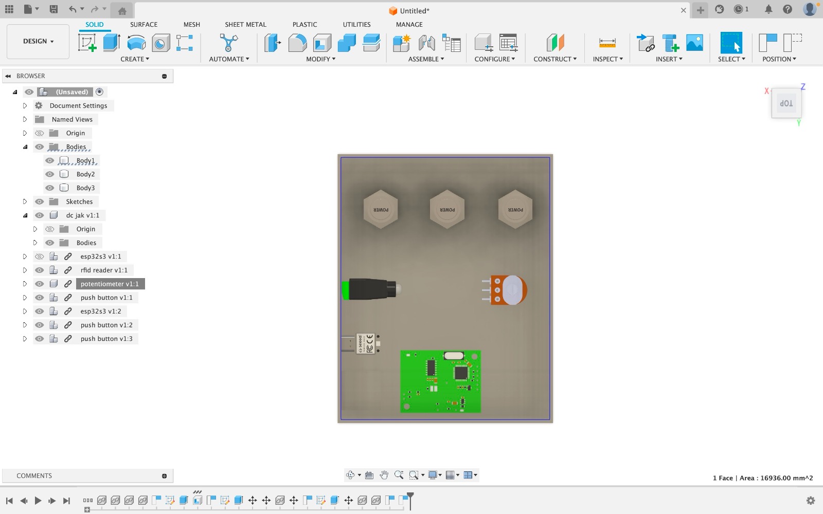
PCB design
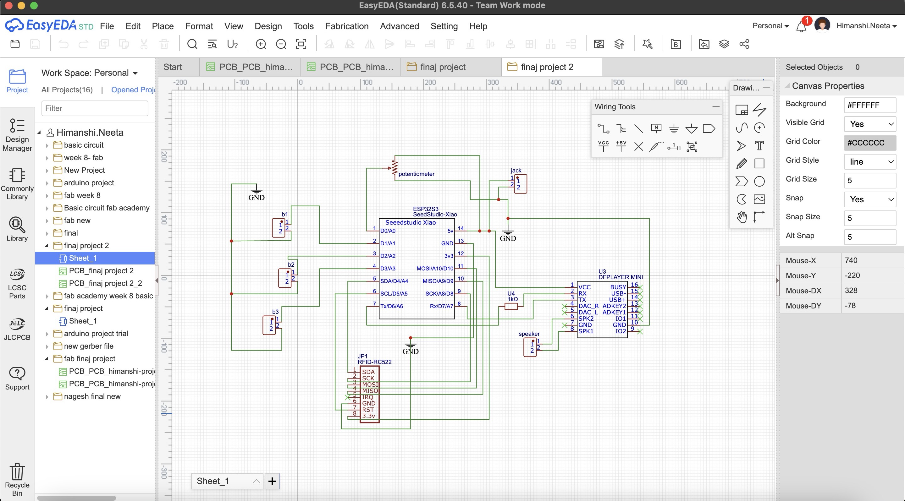
After the placement of components were fixed I started with the pcb design. I did the pcb design on easyeda software to know how to use the software go on Week 8- Electronic Design..
So step 1 was to make a schematic of the connections by taking components from library and making the connections after that is done save the file and go to convert schematic to pcb in design option which is on the top nav bar.
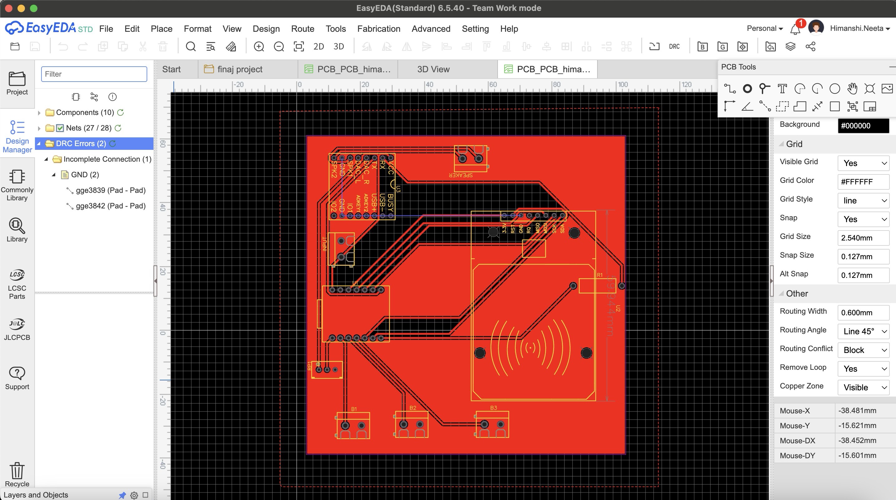
Then I selected the rectangle of 10 by 10cm as we wanted and placed the component how I needed for it to be fit on the case as shown in placing the components parts. I wanted to make a single sided pcb as that is more convinient and easy to use but when I saved my file and did auto routing there were many errors as shown in the image below, the connections were too complicated.
Then I designed double sided pcb and there were no errors.
After designing double sided pcb I realised we don't have the relivent tool for doing double sided pcb so it was not possible for the tools to come as the wait time was long.
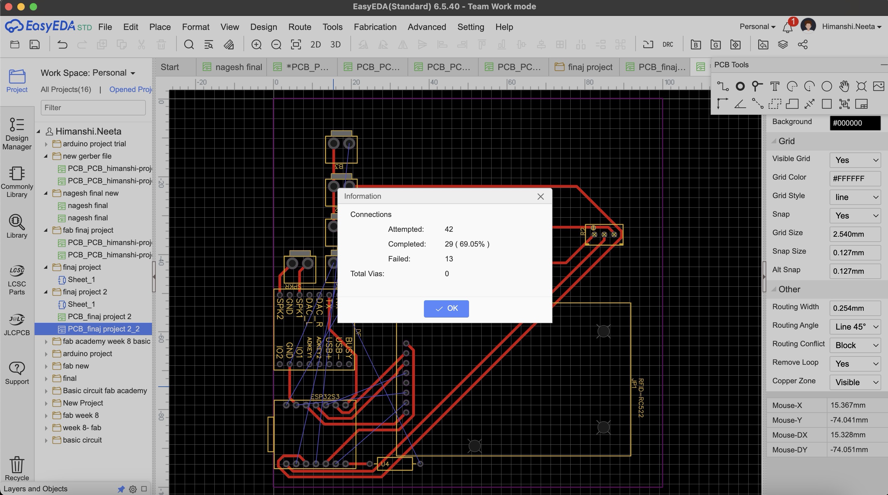
So after this again I did maultiple try and error for single sided pcb and this time I did routing manually as auto routing was failing and then in DRC check there were only 2 errors.
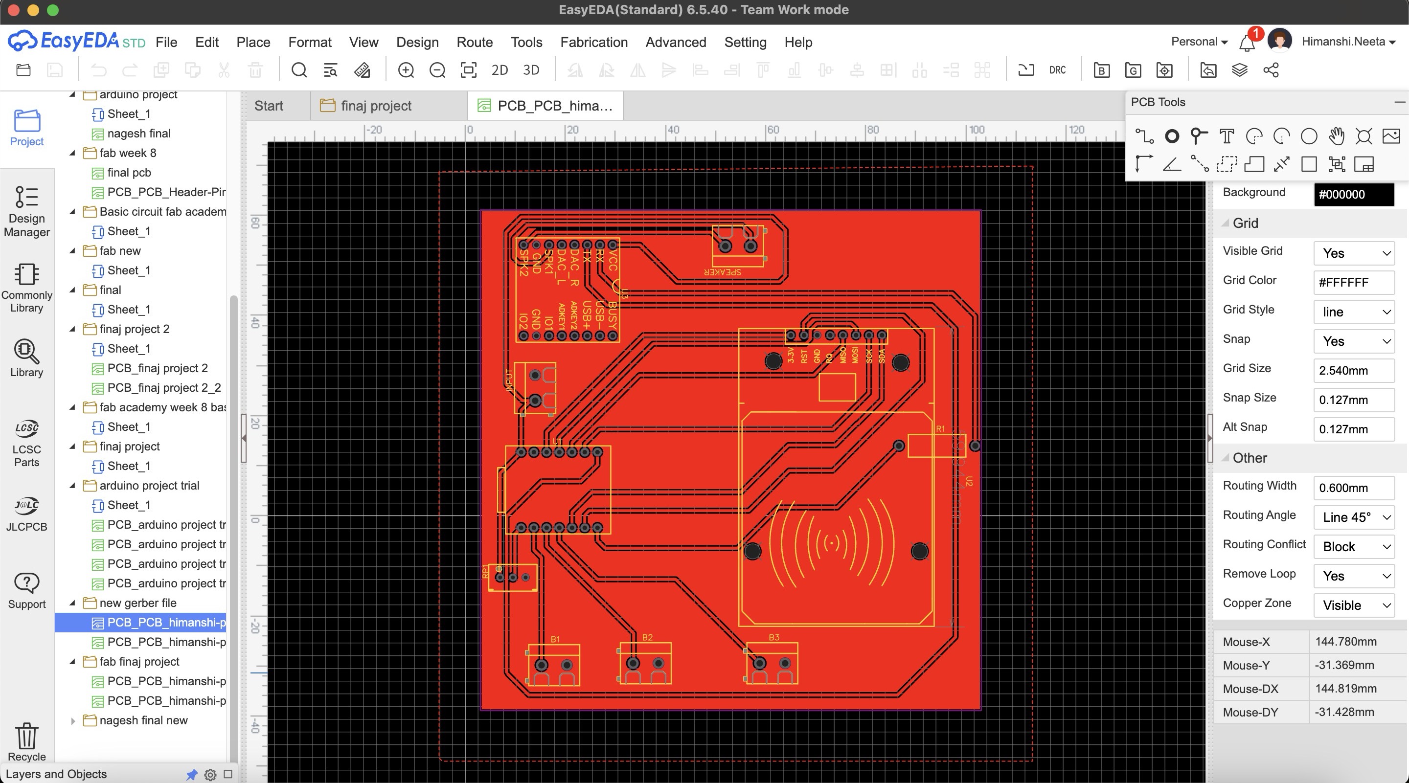
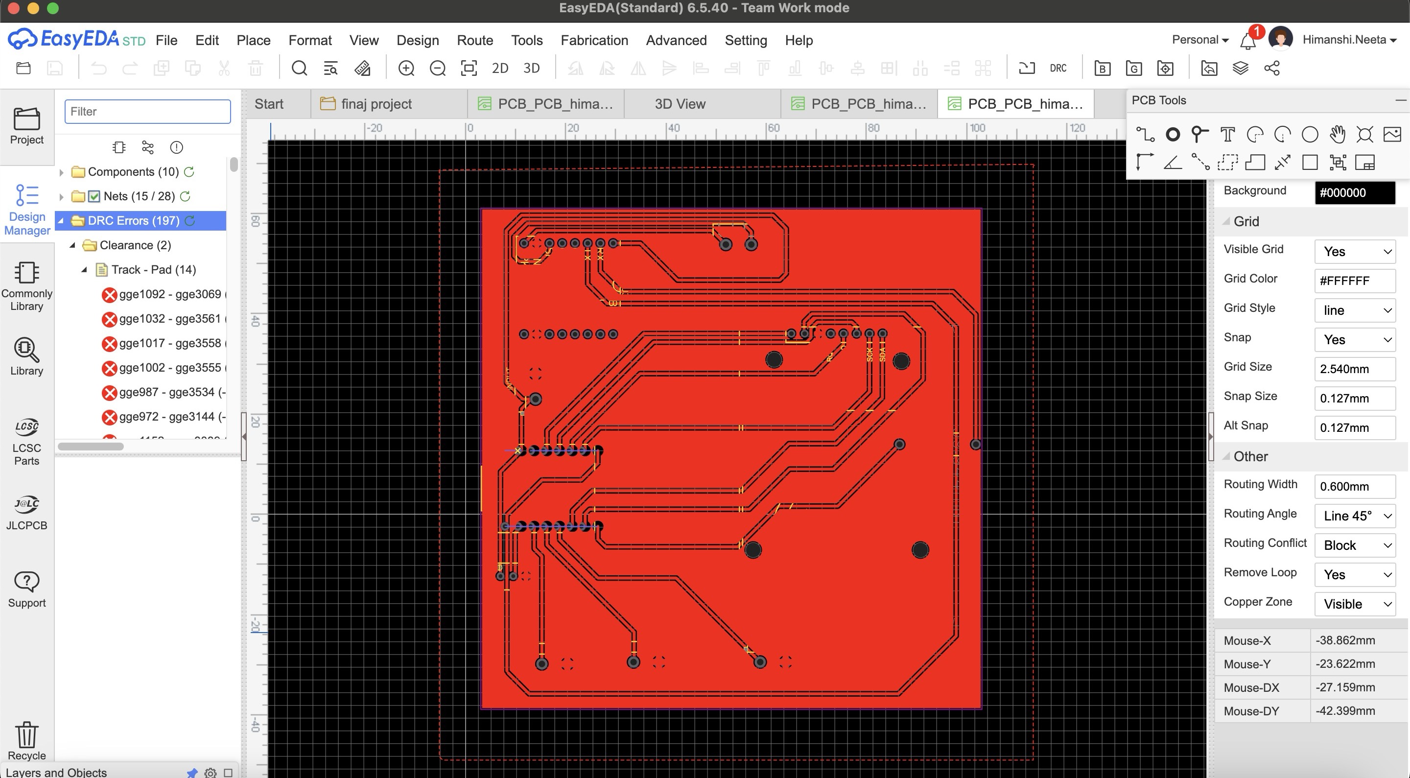
After multiple try and error I got an idea that I'll make common gnd o the entire copper plate, so I designed it accordingly and in the single sided pcb this time again multiple errors as I did auto routing.
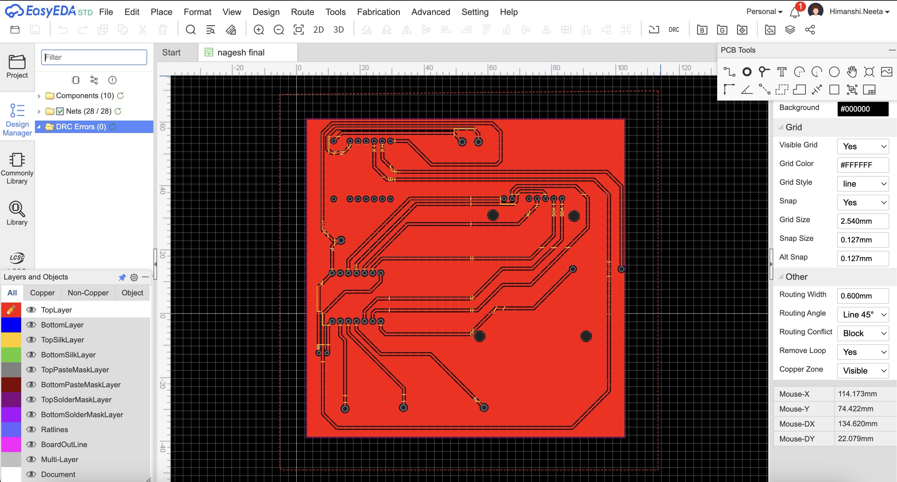
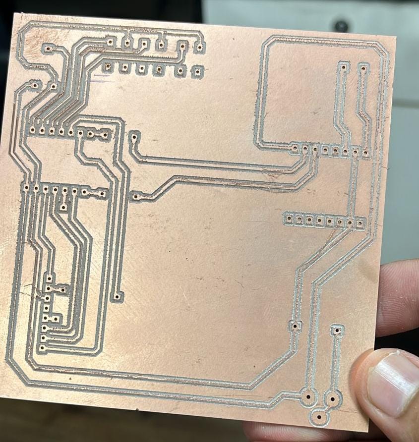
Then I again did the routing manually and finally there were no errors and it is looking perfect now.
PCB Milling
After that I started milling this file, I used SRM20 machine and coppercam software. All the steps of how to use machine and software is mentioned in Week 8- Electronic Production.
Hero Shot
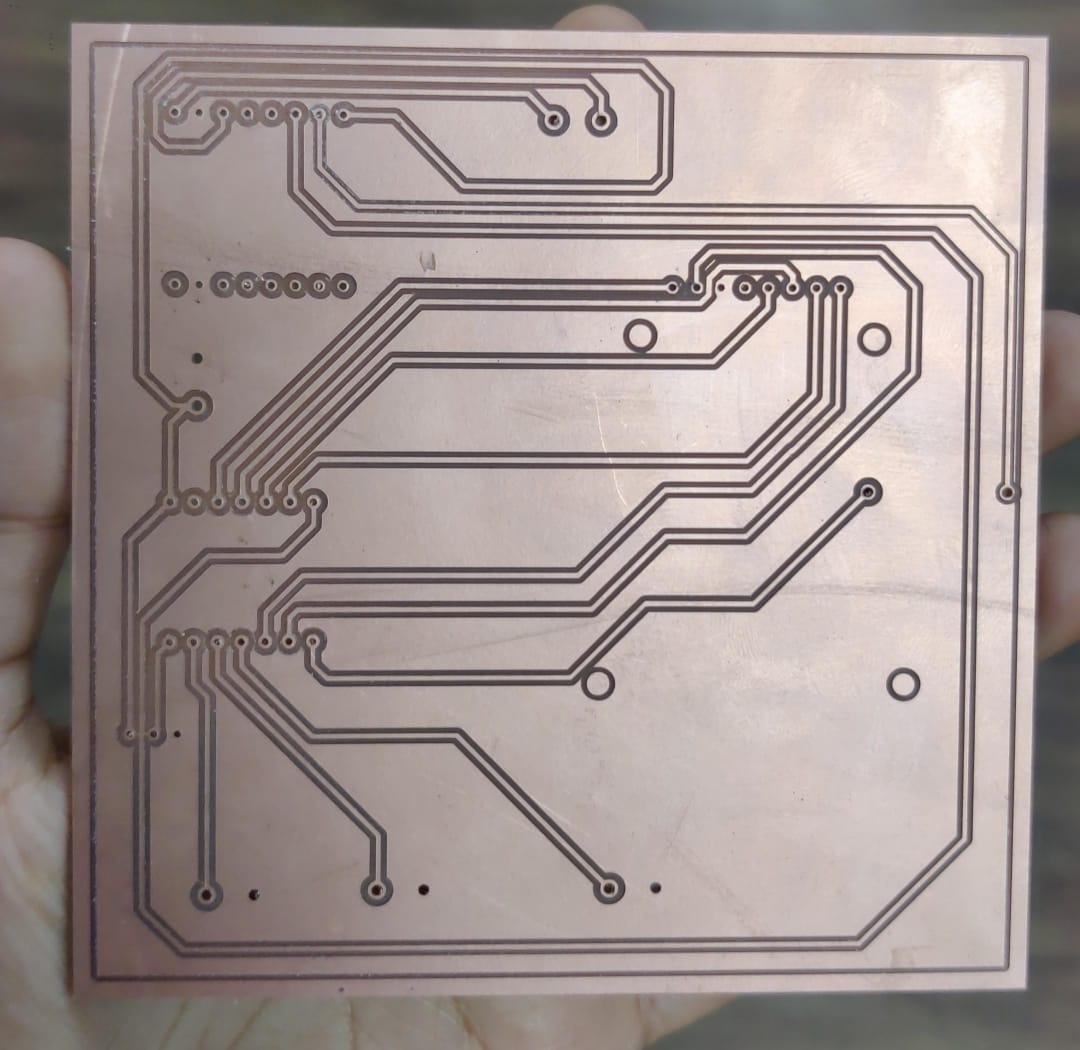
After milling I realised that I should have mirrored the file in copper cam because now the components will be difficult to solder from top, the components should be soldered from below and not from up.
Then I milled a new pcb and in that I mirrored the file
Multimeter testing
After soldering and before soldering too, I tested the connections with the help of multimeter.
Code
What does this code do?
This Arduino code integrates an RFID reader and a DFPlayer Mini MP3 player to create an interactive audio playback system. It uses the MFRC522 RFID module to detect RFID cards and the DFRobotDFPlayerMini library to control the MP3 player. The code initializes the RFID reader and sets up pins for three buttons: start, stop, and pause. When an RFID card is detected, its UID is compared against predefined UIDs stored in an array. If a match is found, the corresponding audio file is played from the MP3 player. The code also reads a potentiometer value to dynamically adjust the volume. Additionally, pressing the start button plays a default audio file, the stop button stops the playback, and the pause button pauses the playback. Debug messages are printed to the serial monitor for monitoring the system's status.
    #include
      #include
      #include

      // RFID RC522 pins
      #define SS_PIN 6
      #define RST_PIN 5

      // Button pins
      #define START_BUTTON_PIN 2
      #define STOP_BUTTON_PIN 3
      #define PAUSE_BUTTON_PIN 4

      MFRC522 mfrc522(SS_PIN, RST_PIN);
      DFRobotDFPlayerMini myDFPlayer;

      // Map RFID card UIDs to sound file numbers
      const byte cardUIDs[10][4] = {
        { 0xE0, 0x14, 0xC6, 0x3B },
        { 0x50, 0x5A, 0x77, 0x59 },
        { 0x43, 0x85, 0x12, 0x50 },
        { 0x93, 0xDB, 0x02, 0xE4 },
        { 0x24, 0xAE, 0xD0, 0x09 },
        { 0xD3, 0xA0, 0x67, 0x1A },
        { 0xD3, 0xA0, 0x67, 0x1A },
        { 0xE3, 0x2B, 0xA2, 0xE4 },
        { 0x43, 0x75, 0xAD, 0xE4 },
        { 0xC3, 0x80, 0x50, 0x1D }
      };

      void setup() {
        Serial.begin(9600);  // Initialize hardware serial for DFPlayer Mini at 9600 baud
        Serial1.begin(9600, SERIAL_8N1, 44, 43);
        SPI.begin();         // Init SPI bus
        mfrc522.PCD_Init();  // Init MFRC522

        pinMode(START_BUTTON_PIN, INPUT_PULLUP);
        pinMode(STOP_BUTTON_PIN, INPUT_PULLUP);
        pinMode(PAUSE_BUTTON_PIN, INPUT_PULLUP);
        pinMode(1,INPUT_PULLUP);
        if (!myDFPlayer.begin(Serial1)) {
          Serial.println(F("Unable to begin:"));
          Serial.println(F("1.Please recheck the connection!"));
          Serial.println(F("2.Please insert the SD card!"));
          while (true)
            ;
        }
        myDFPlayer.volume(30);  // Set volume value (0~30).

        Serial.println(F("Place your RFID card near the reader..."));
      }

      void loop() {
        int potValue = analogRead(1);

        int vol = map(potValue, 0, 4096, 0, 30);
        vol = constrain(vol,0,30);
        myDFPlayer.volume(vol);
        Serial.println("Volume: "+String(vol));
        Serial.println("Button Start: " + String(digitalRead(START_BUTTON_PIN)));
        Serial.println("Button Stop: " + String(digitalRead(STOP_BUTTON_PIN)));
        Serial.println("Button Pause: " + String(digitalRead(PAUSE_BUTTON_PIN)));
        // Check for button presses
        if (digitalRead(START_BUTTON_PIN) == LOW) {
          myDFPlayer.play(1);  // Play a default audio file (e.g., 0001.mp3)
          Serial.println("Start button pressed, playing default audio.");
          delay(300);  // Debounce delay
        }

        if (digitalRead(STOP_BUTTON_PIN) == LOW) {
          myDFPlayer.stop();
          Serial.println("Stop button pressed, stopping audio.");
          delay(300);  // Debounce delay
        }

        if (digitalRead(PAUSE_BUTTON_PIN) == LOW) {
          myDFPlayer.pause();
          Serial.println("Pause button pressed, pausing audio.");
          delay(300);  // Debounce delay
        }

        // RFID code
        if (mfrc522.PICC_IsNewCardPresent() && mfrc522.PICC_ReadCardSerial()) {
          // Print Card UID in the desired format
          Serial.print("{");
          for (byte i = 0; i < mfrc522.uid.size; i++) {
            Serial.print("0x");
            Serial.print(mfrc522.uid.uidByte[i], HEX);
            if (i < mfrc522.uid.size - 1) {
              Serial.print(", ");
            }
          }
          Serial.println("}");

          // Compare the read UID with the predefined UIDs
          for (int i = 0; i < 10; i++) {
            if (memcmp(mfrc522.uid.uidByte, cardUIDs[i], 4) == 0) {
              Serial.print("Playing sound for card ");
              Serial.println(i + 1);
              myDFPlayer.play(i + 1);  // Play the corresponding MP3 file (files should be named 0001.mp3, 0002.mp3, etc.)
              break;
            }
          }

          delay(1000);
        }
        delay(100);
      }
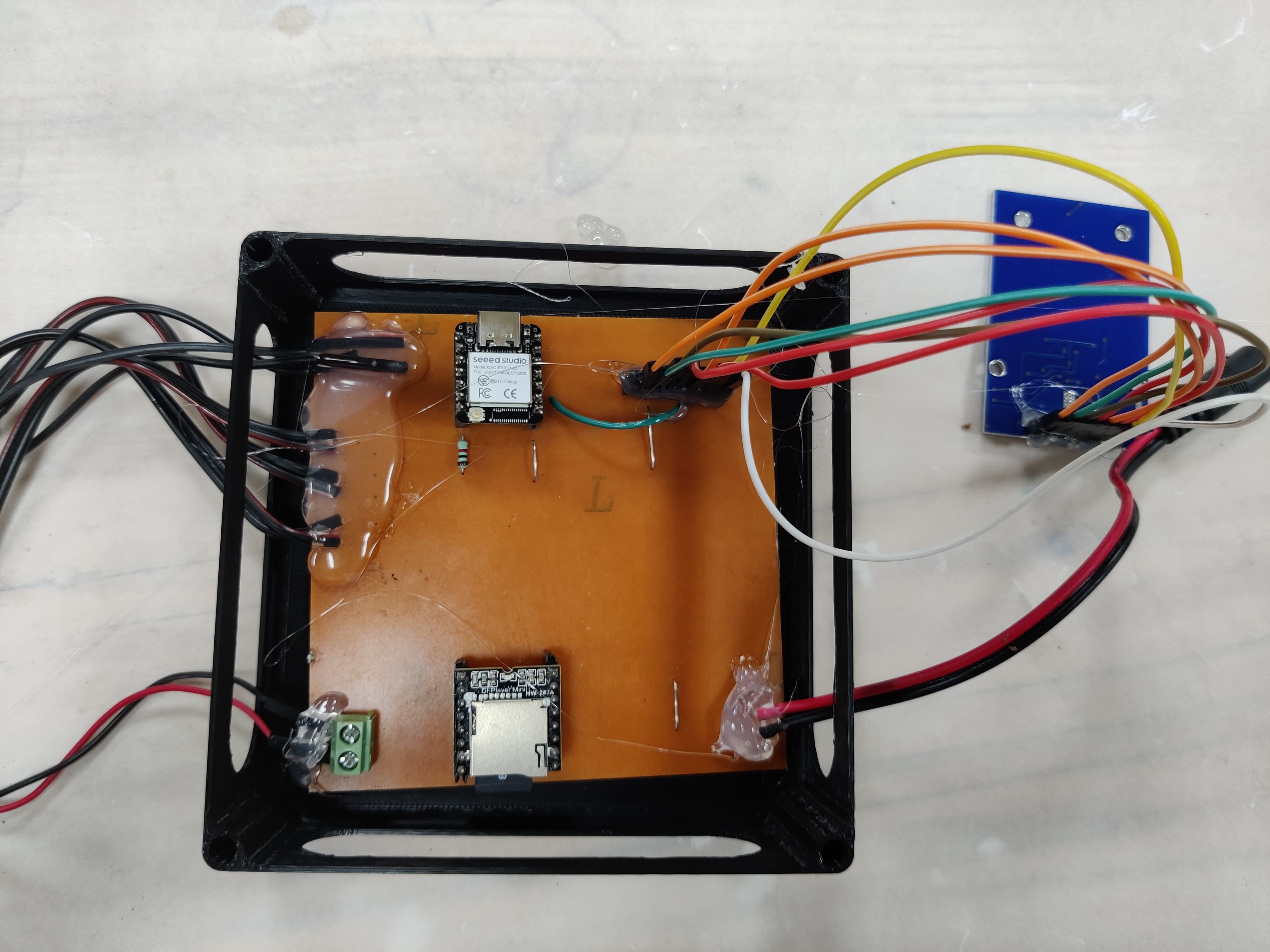
HeroShot of PCB
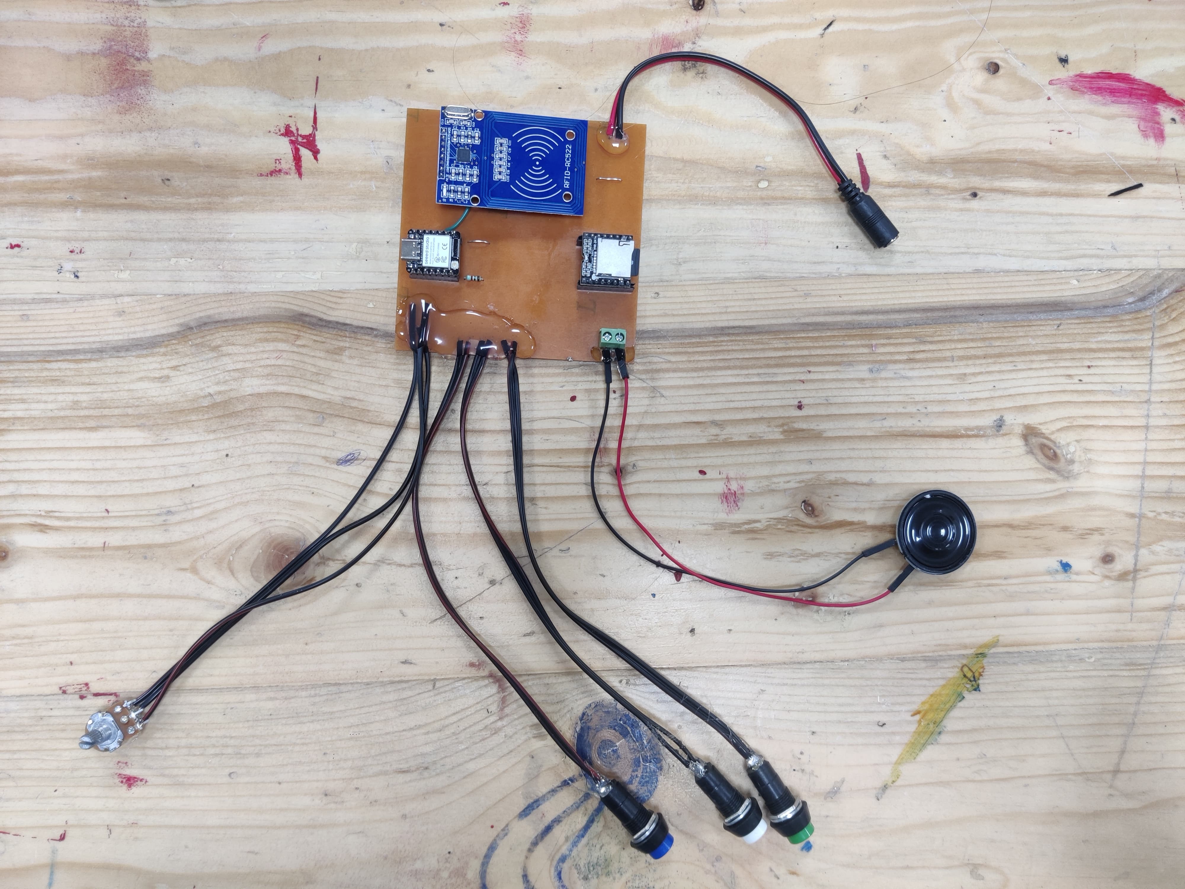
WOrking of PCB
After that I made the design for pcb and milled it and tried out the circuit on that.
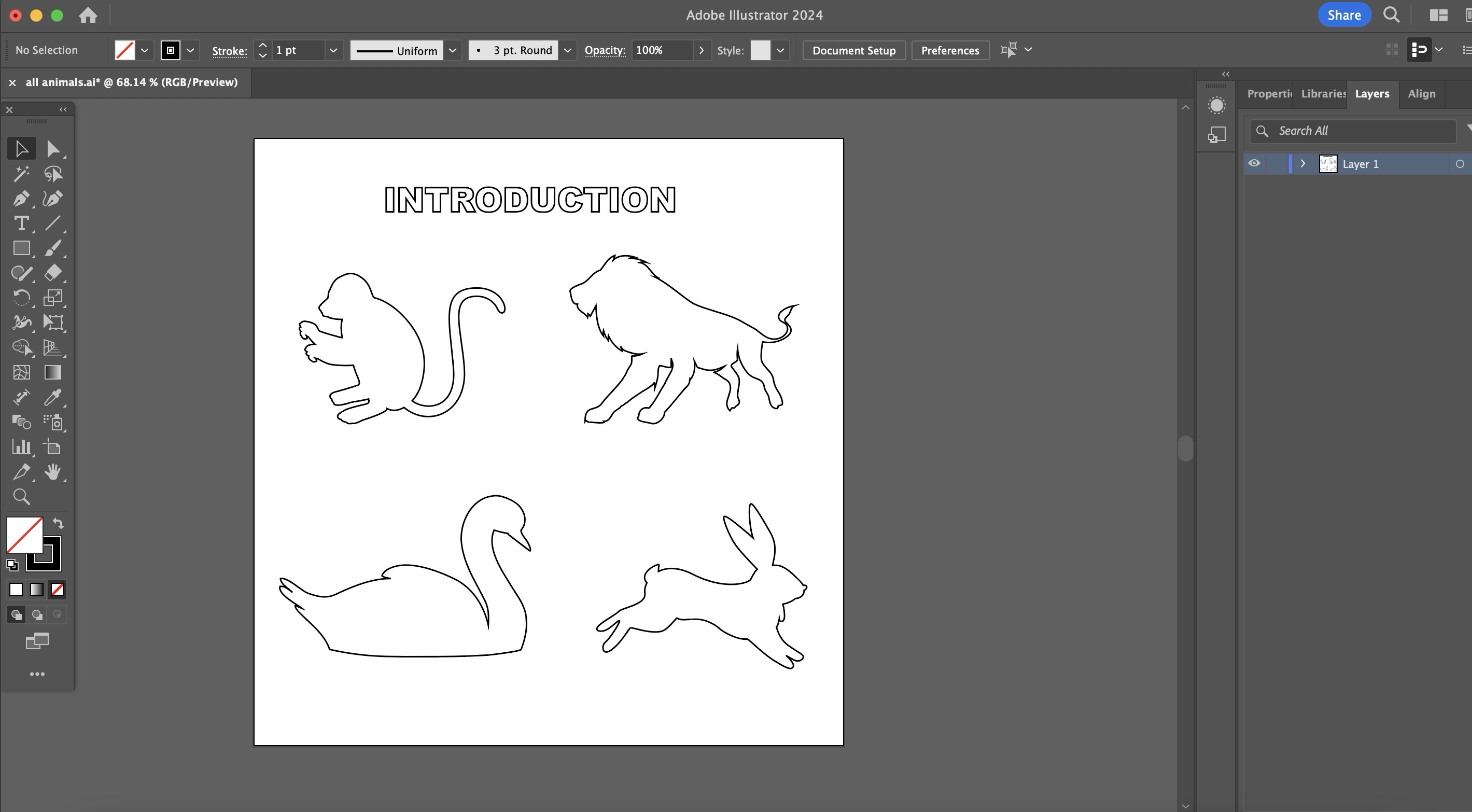
2d CAD Design
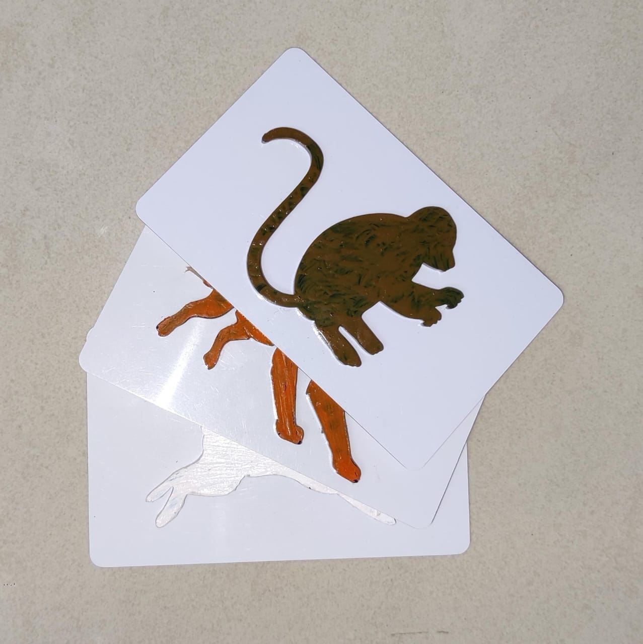
I used illustrator as a software for making 2d design, as mentioned earlier I wanted embossed shape of animals so I made the design of animals and then did the laser cutting.
Laser cutting
I used laser cutting for cutting the animals shape as mentioned above for putting it on the rfid cards, so previously I had tested that the distance of the rfid card and reader is 2cm by that I mean it can read the card till 2cm distance only. I used 3mm acrylic for the same.
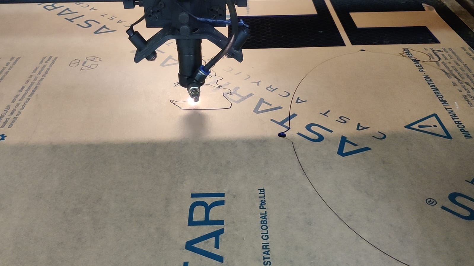
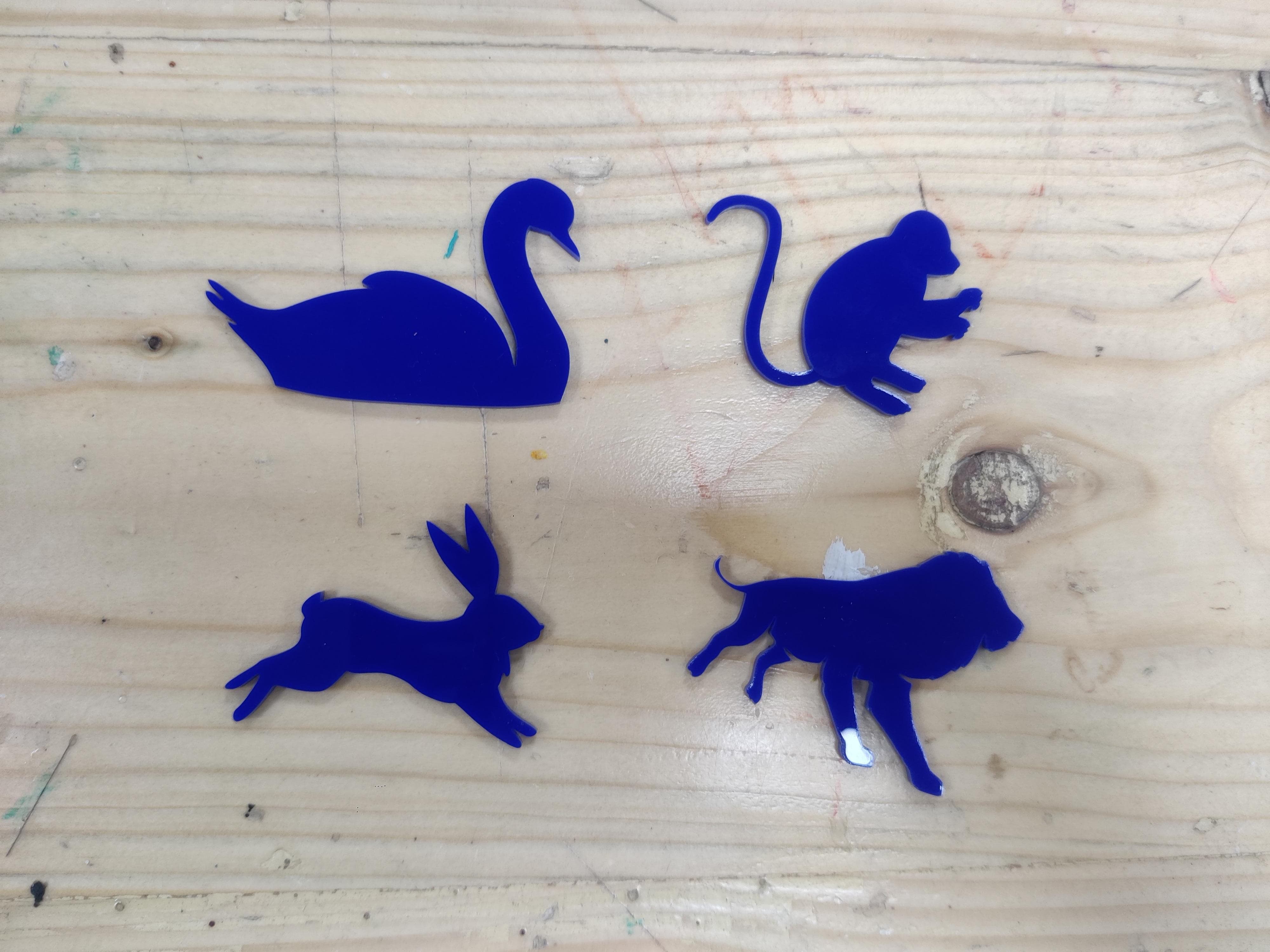
After laser cutting I painted the pieces with the help of acrylic paint depending on which animal it was.
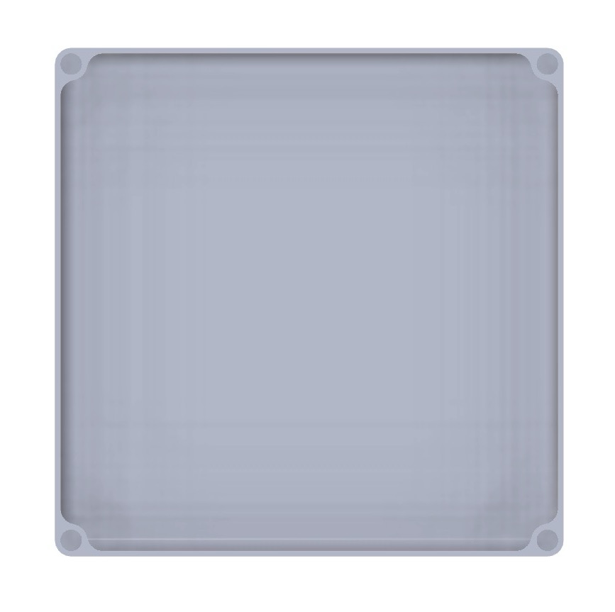
3d Modelling
As I ideated for the case before making the pcb, I made the 3d model of the case accordingly. This is how the case looks it has 3 parts bottom, middle and top.
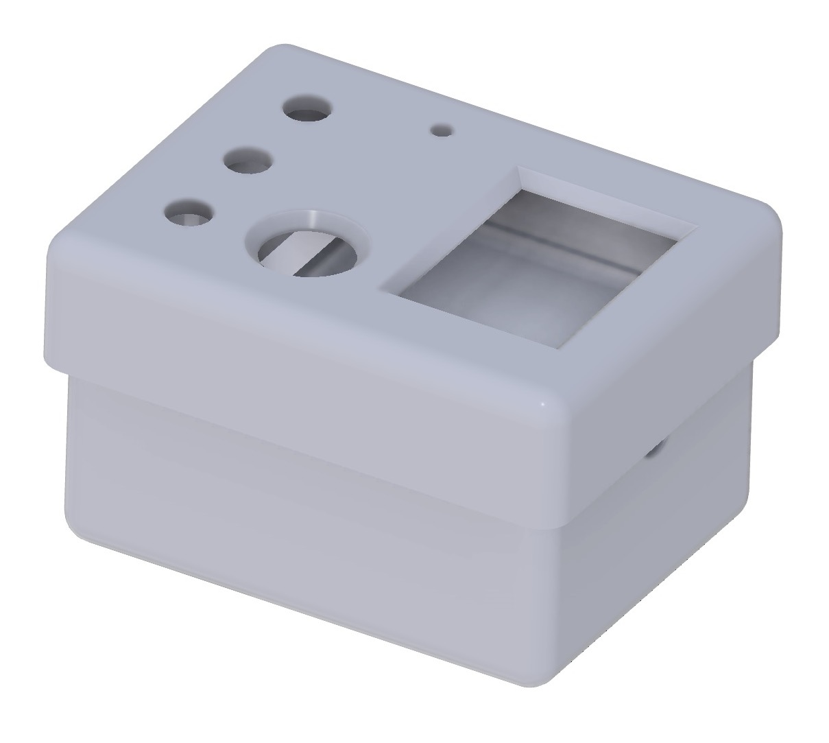
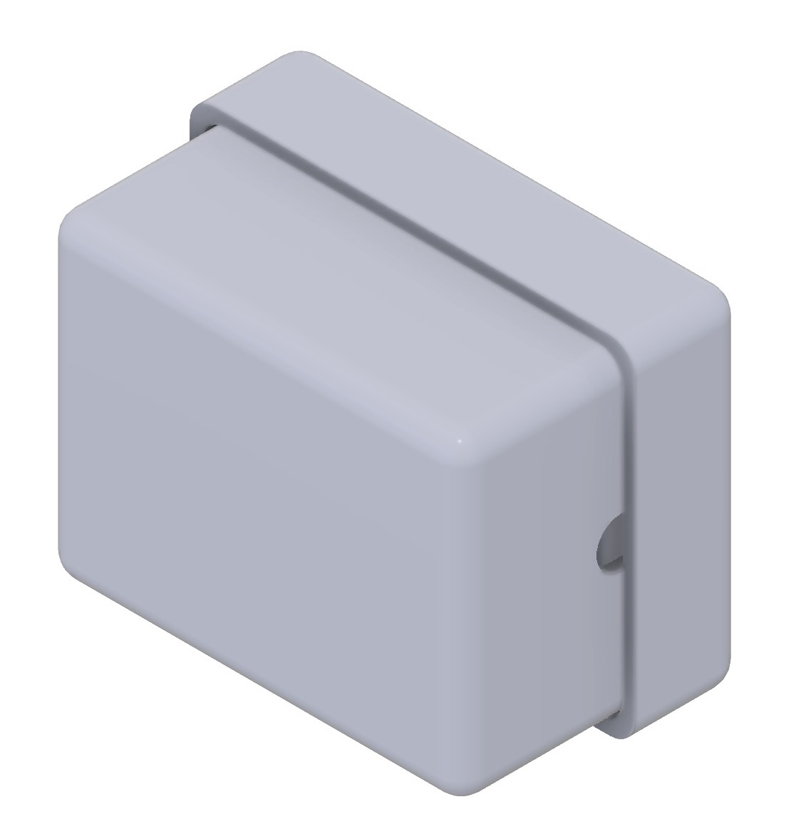
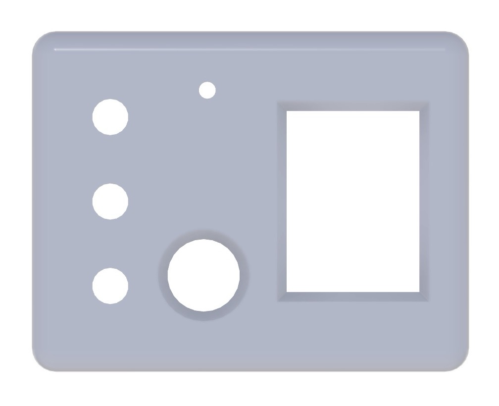
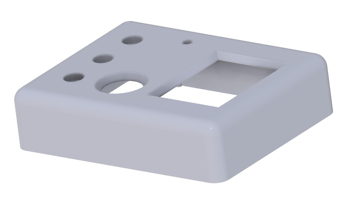
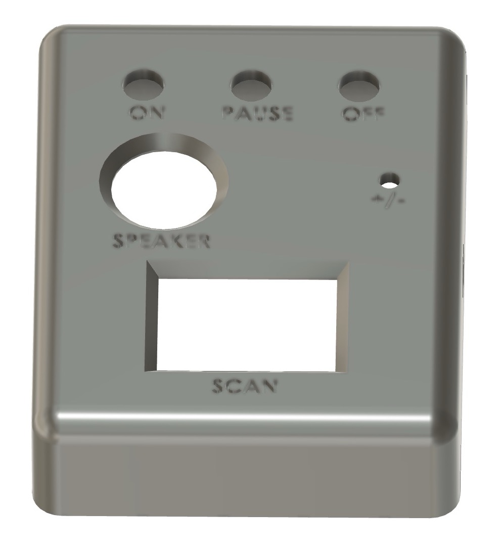
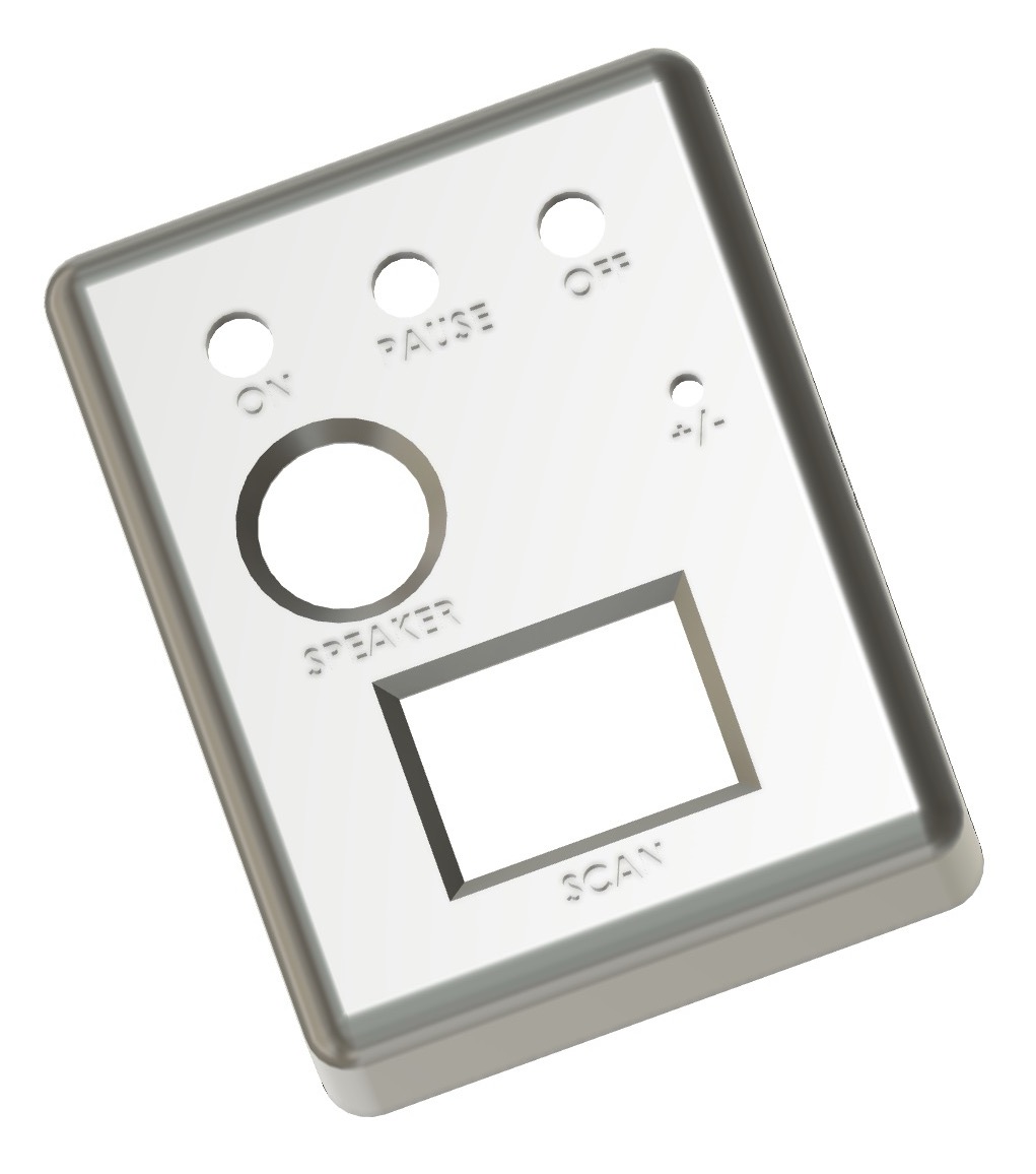
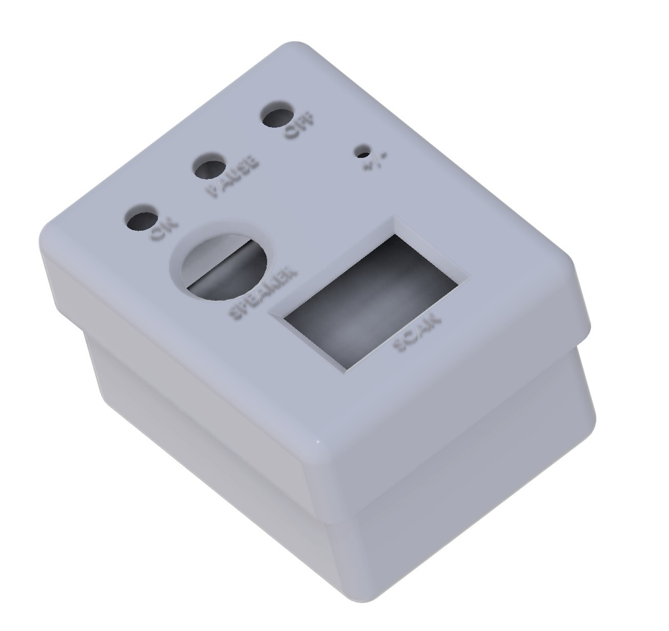
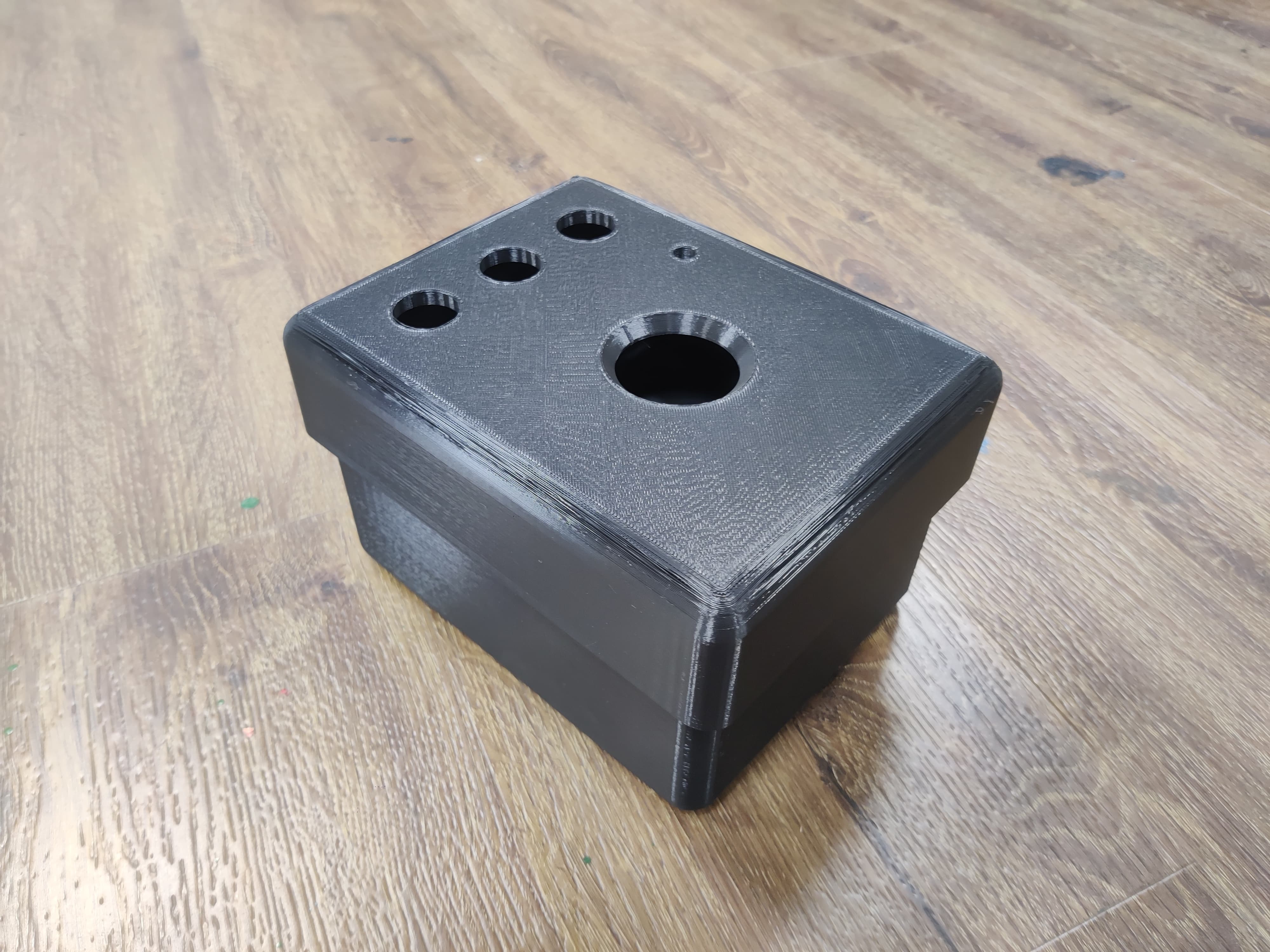
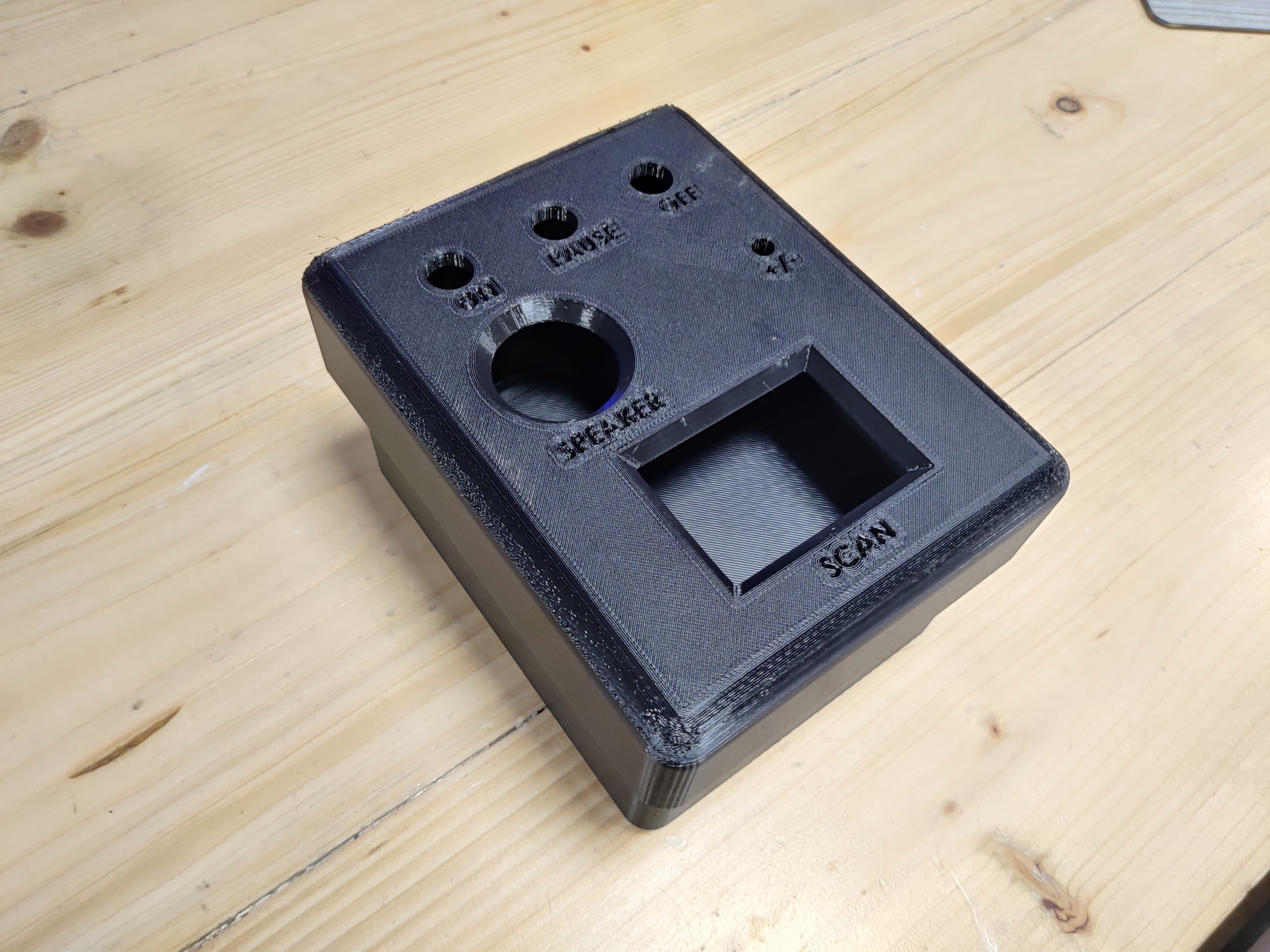
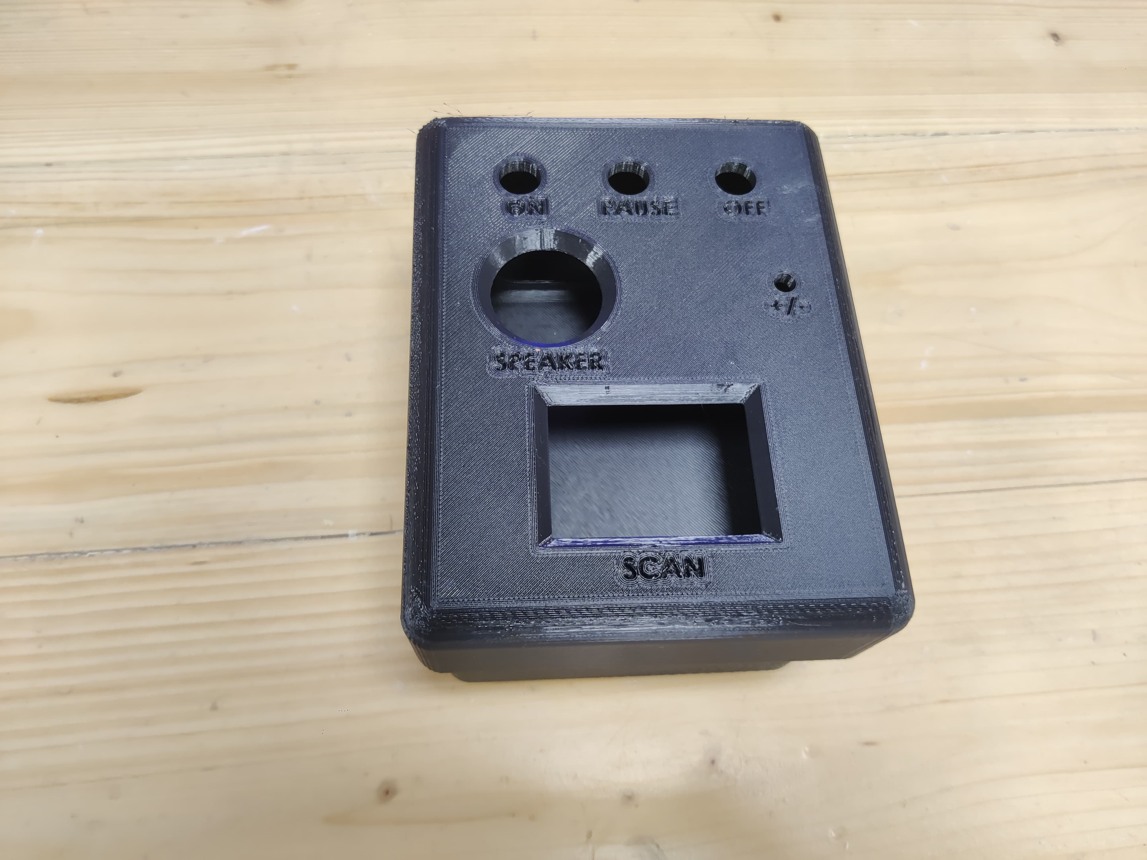
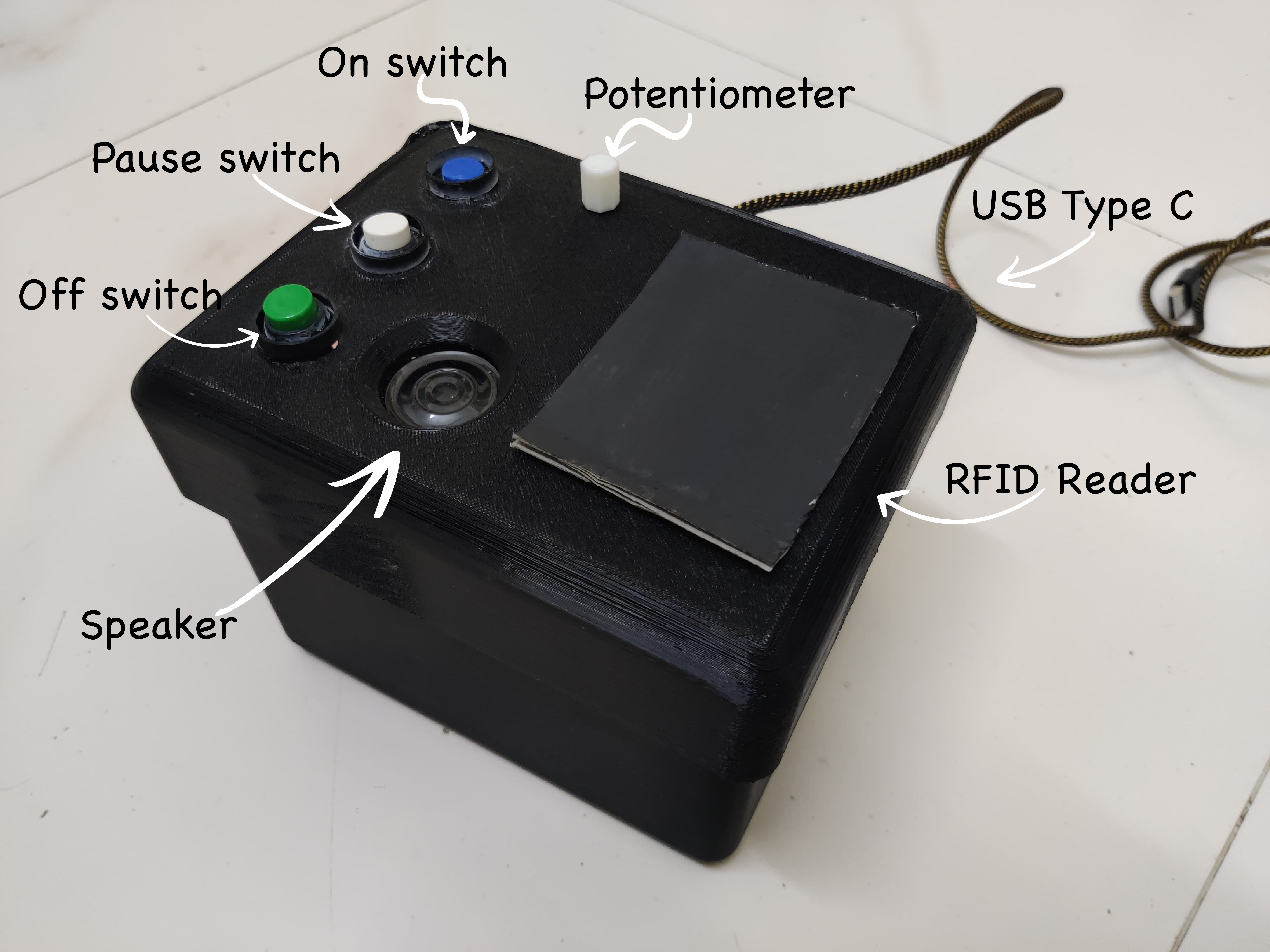
Top part
In the top part I made holes for push buttons, potentiometer, speaker and rfid card.
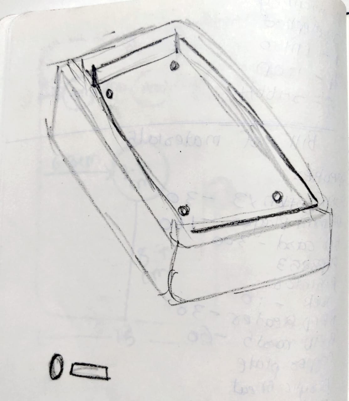
On the nack side of the top part there are stick like thing which will go in th middle part so it is like a joint through which we can remove the entire part and put again.
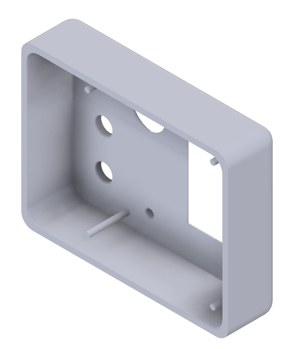
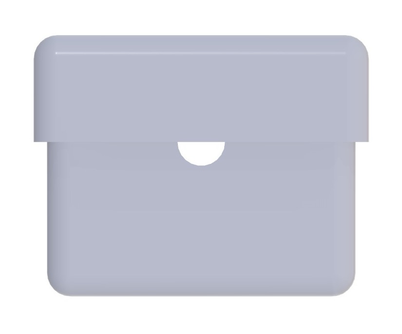
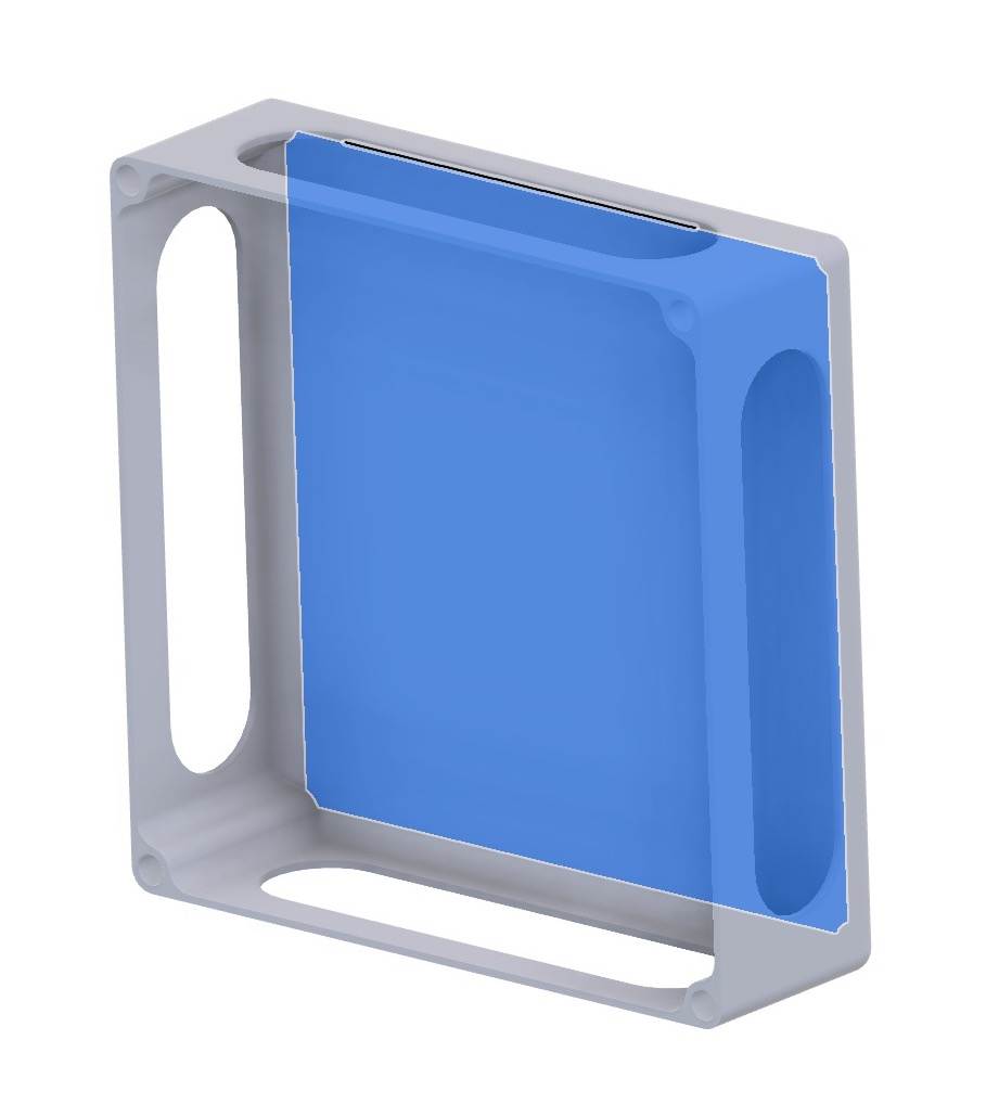
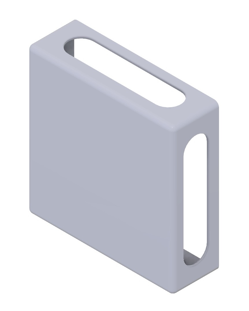
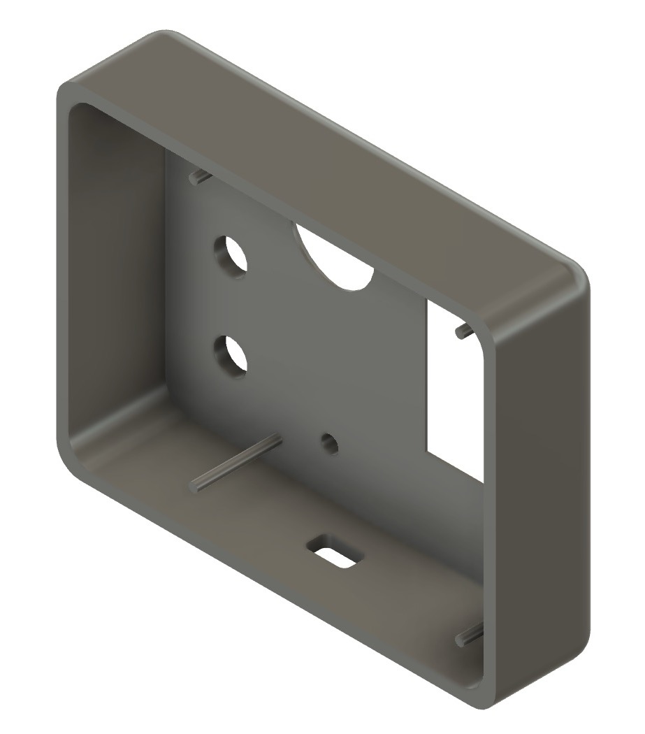
Middle Part
In the middle part there are holes from all the 4 sides for the design to look good and I needed hole actually only on 2 sides for type c wire to come and attach to pcb and the jack connector from other side but even in future if we change the posistion of pcb so it is good to have holes on all 4 sides, also there is holes on 4 corners for that stick to go which is on the top part for the joints.
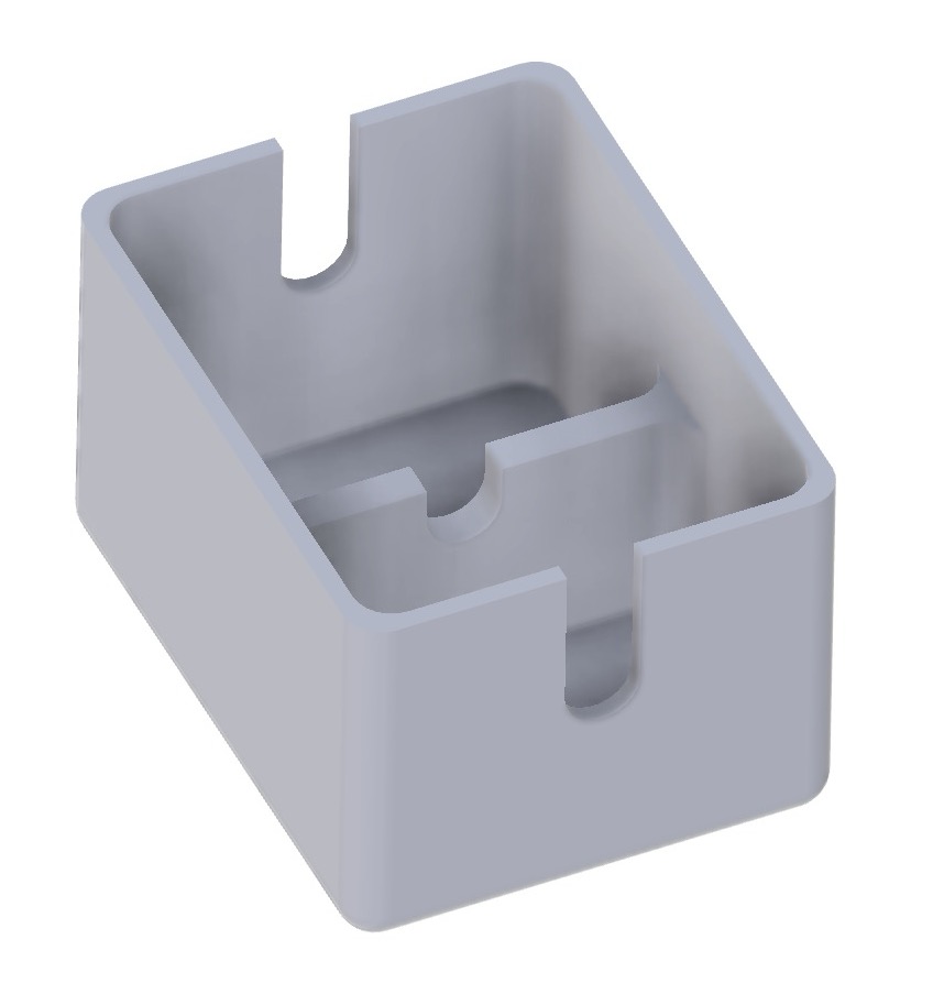
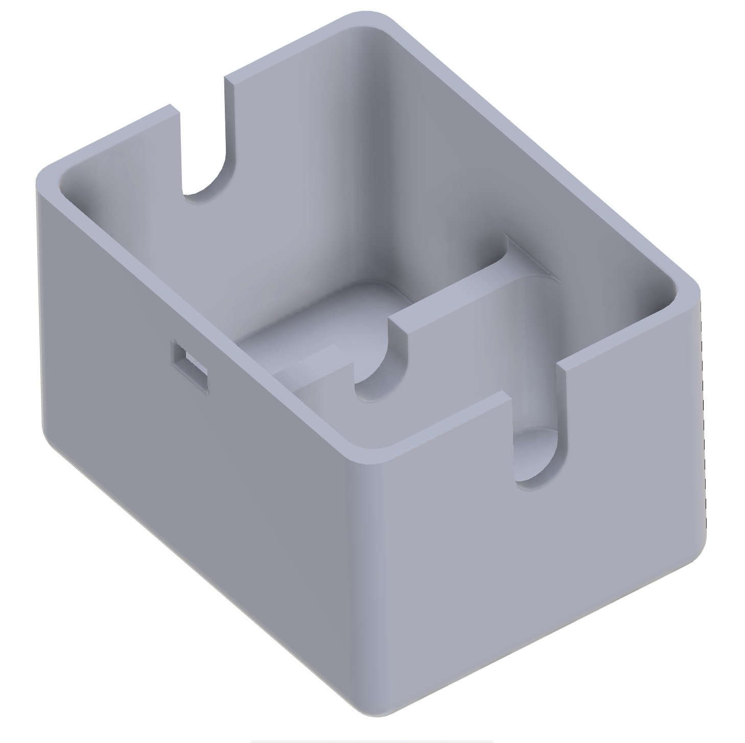
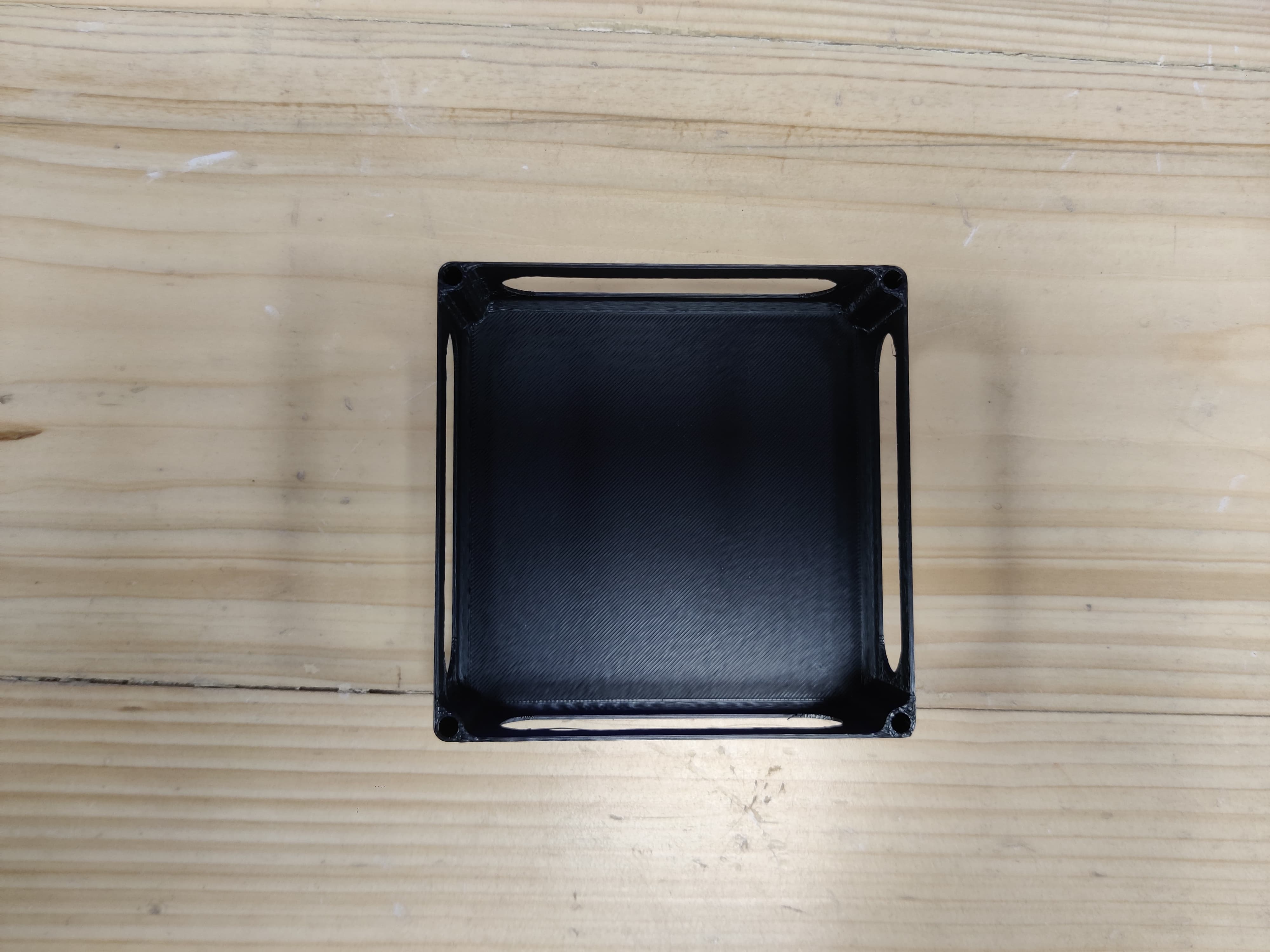
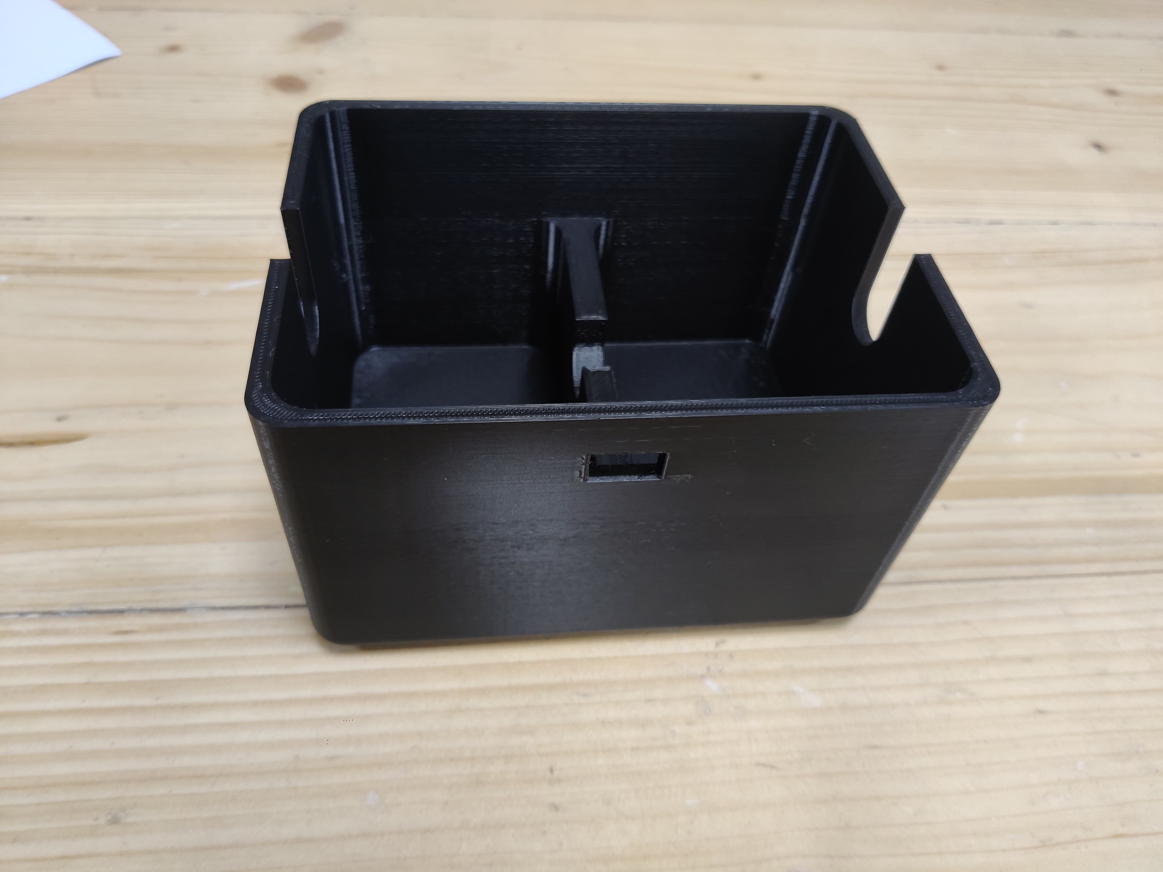
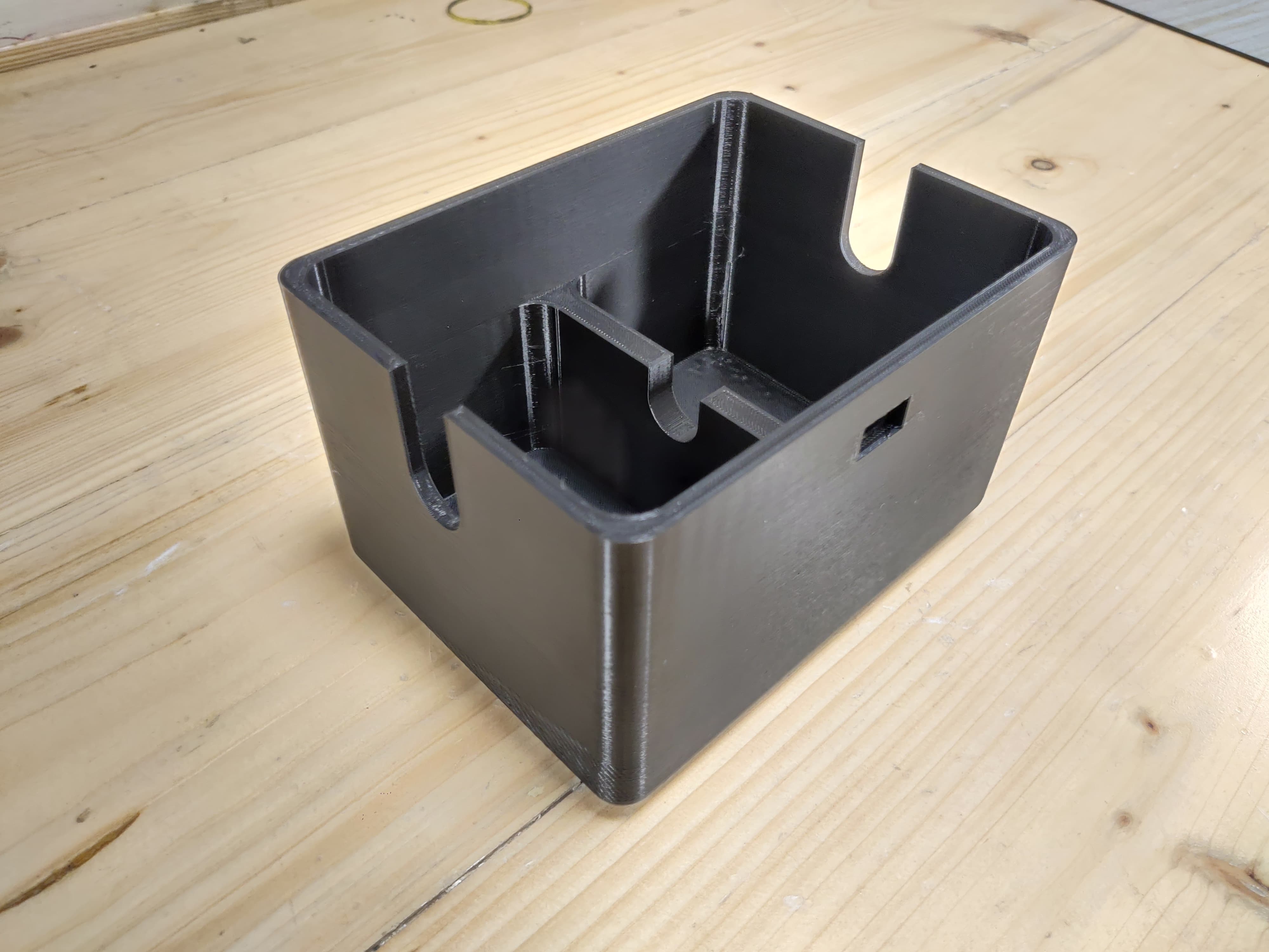
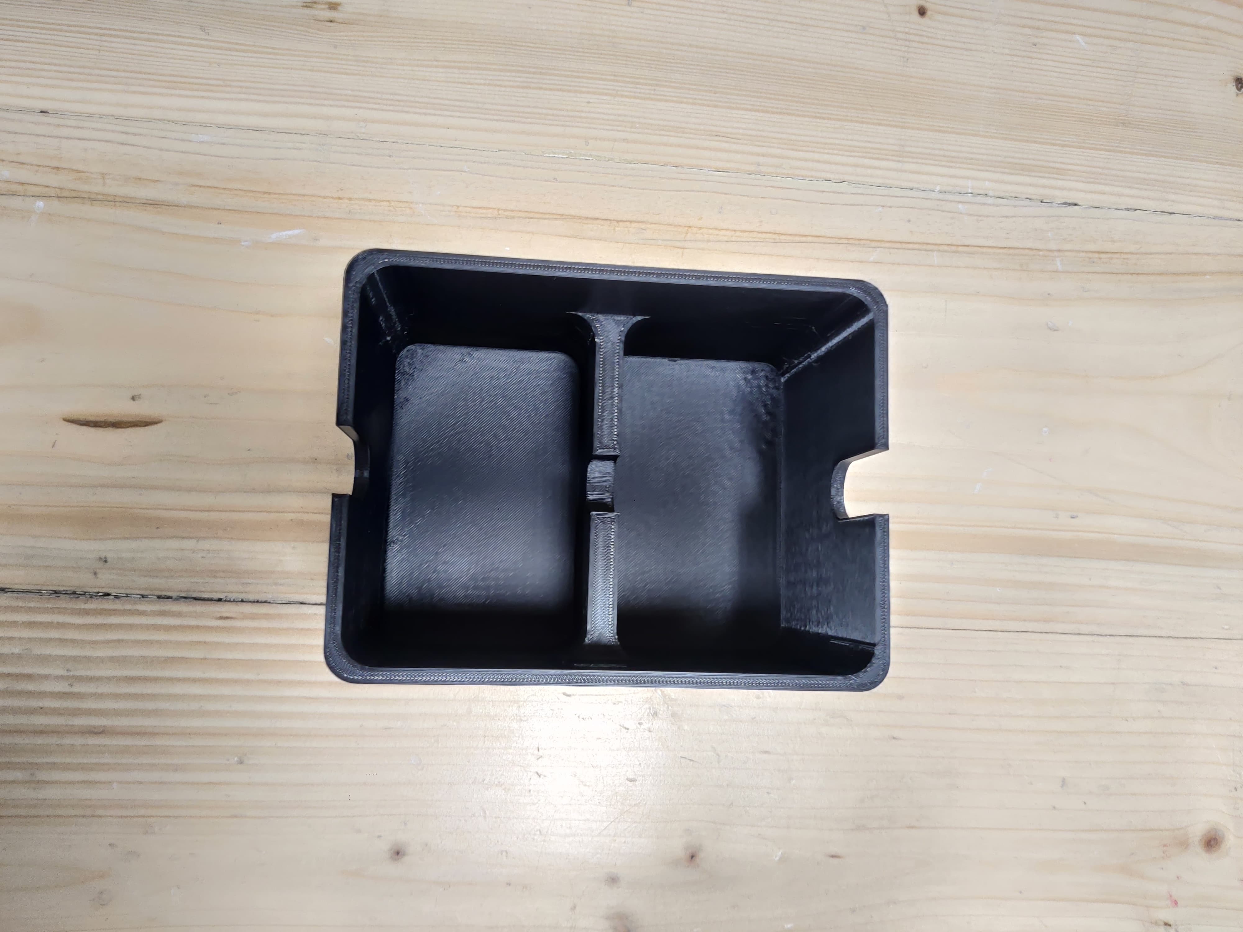
Bottom Part
In the bottom part I have made the divider for the cards so once you use the card you can put it in the second half so that all the cards are not mixed with each other, also from the sides and in between there is a u cut shape through which it is easier to pick up a card and use it.

This is how the model will open and close.
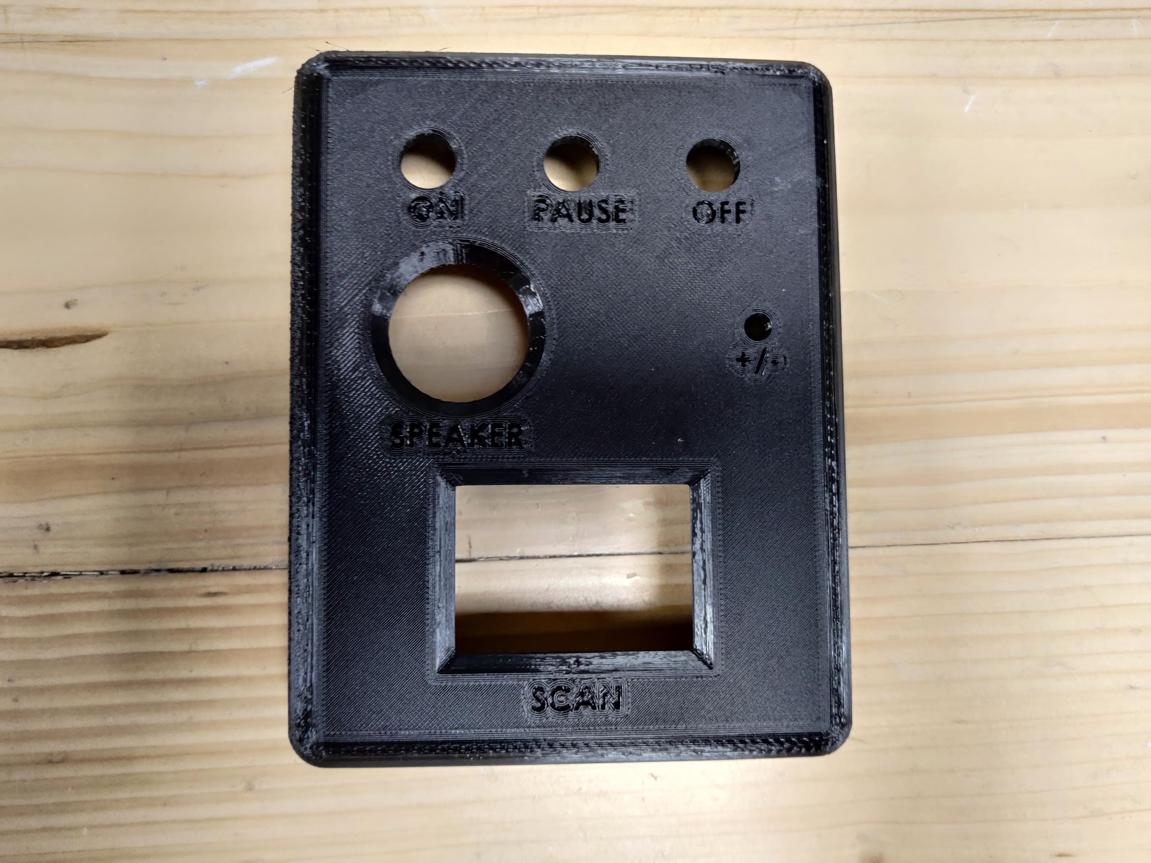
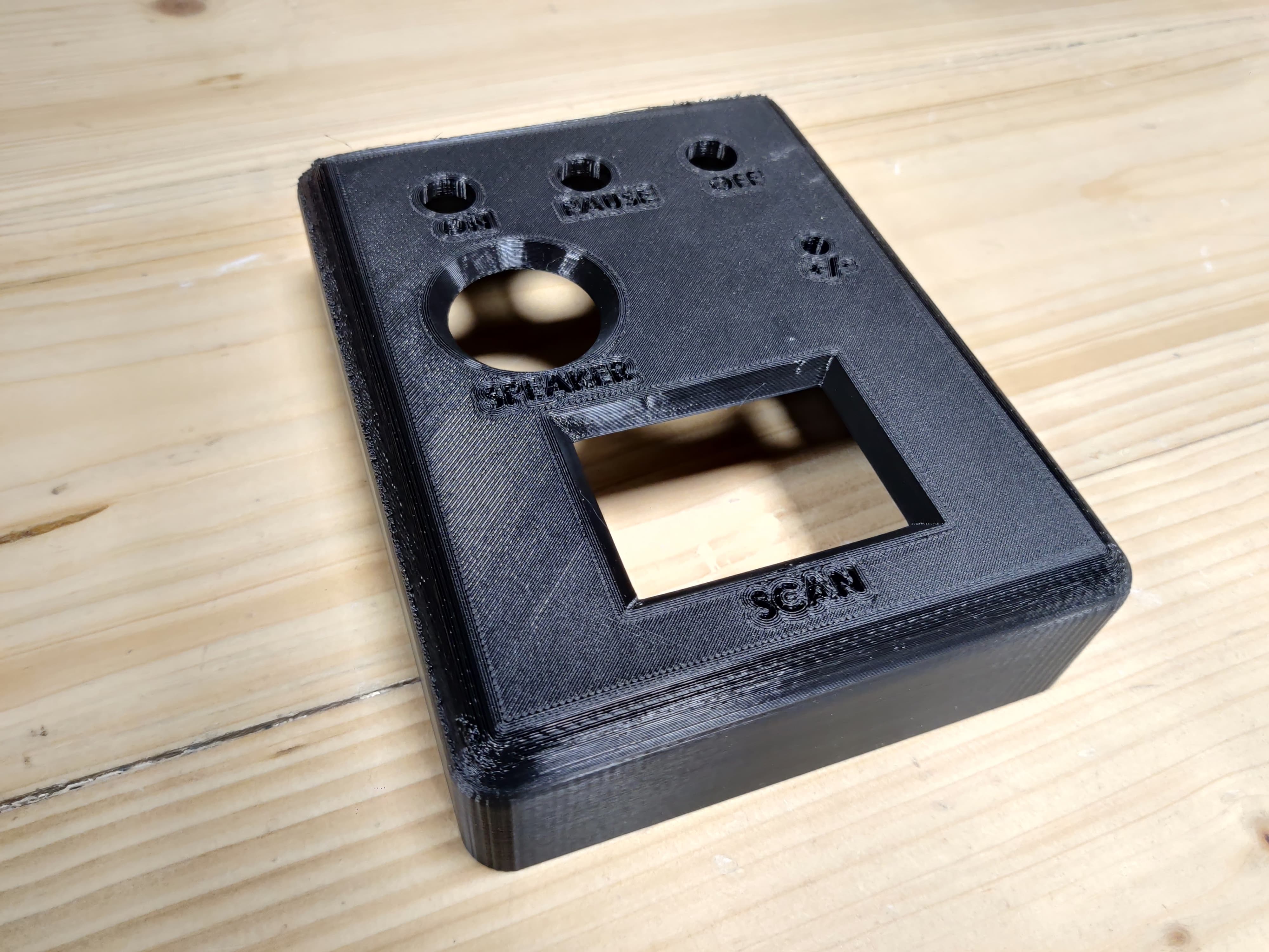
After the final presentation neil suggested me to label all the things in the top part so I changed my case accordingly and labelled it.
I did some more changes at personal level like decreased the size of rfid reader hole, push buttons, speaker in the top part, labelling on top part, on the bottom part I decreased the size of u cut which we can see from sides.
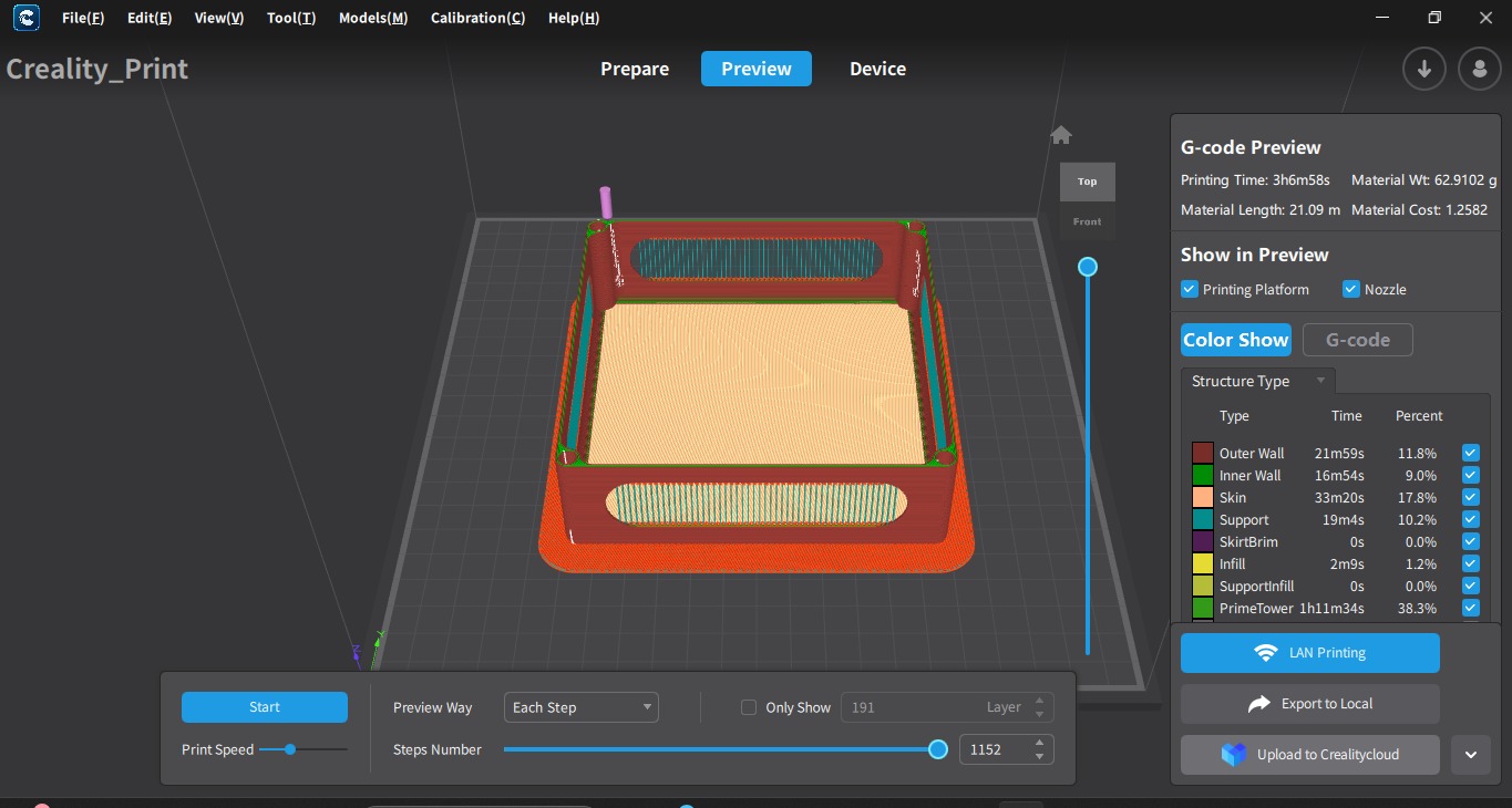
GCode
In detail how to make gcode is explained in the week 5- 3d scanning and printing.
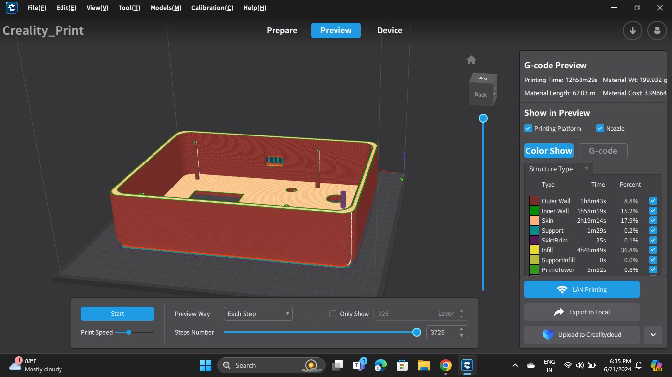
This are some images of how I made gcode for my top part.
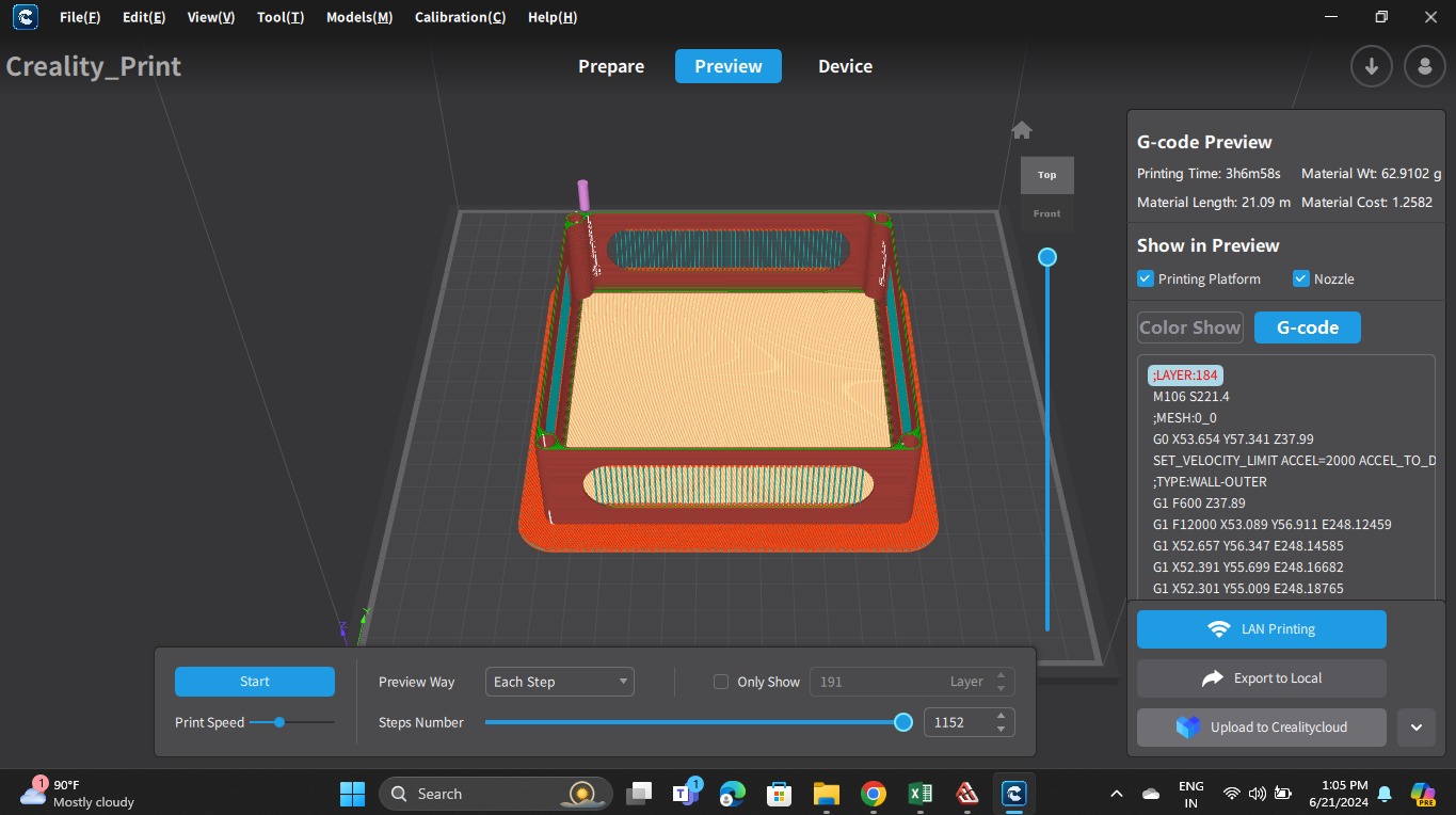
This is for middle part
Changes in 3d modelling
Top part
In the top box I decreased the size of push buttons, speaker, rfid scan box and labelled the buttons and scan me on the box.
Bottom Part
In the bottom part the U cut was looking too big, so even after closing the box the U cut was seen so I decreased the size of that too. I also added a hole on side for the type c wire to attach to pcb.

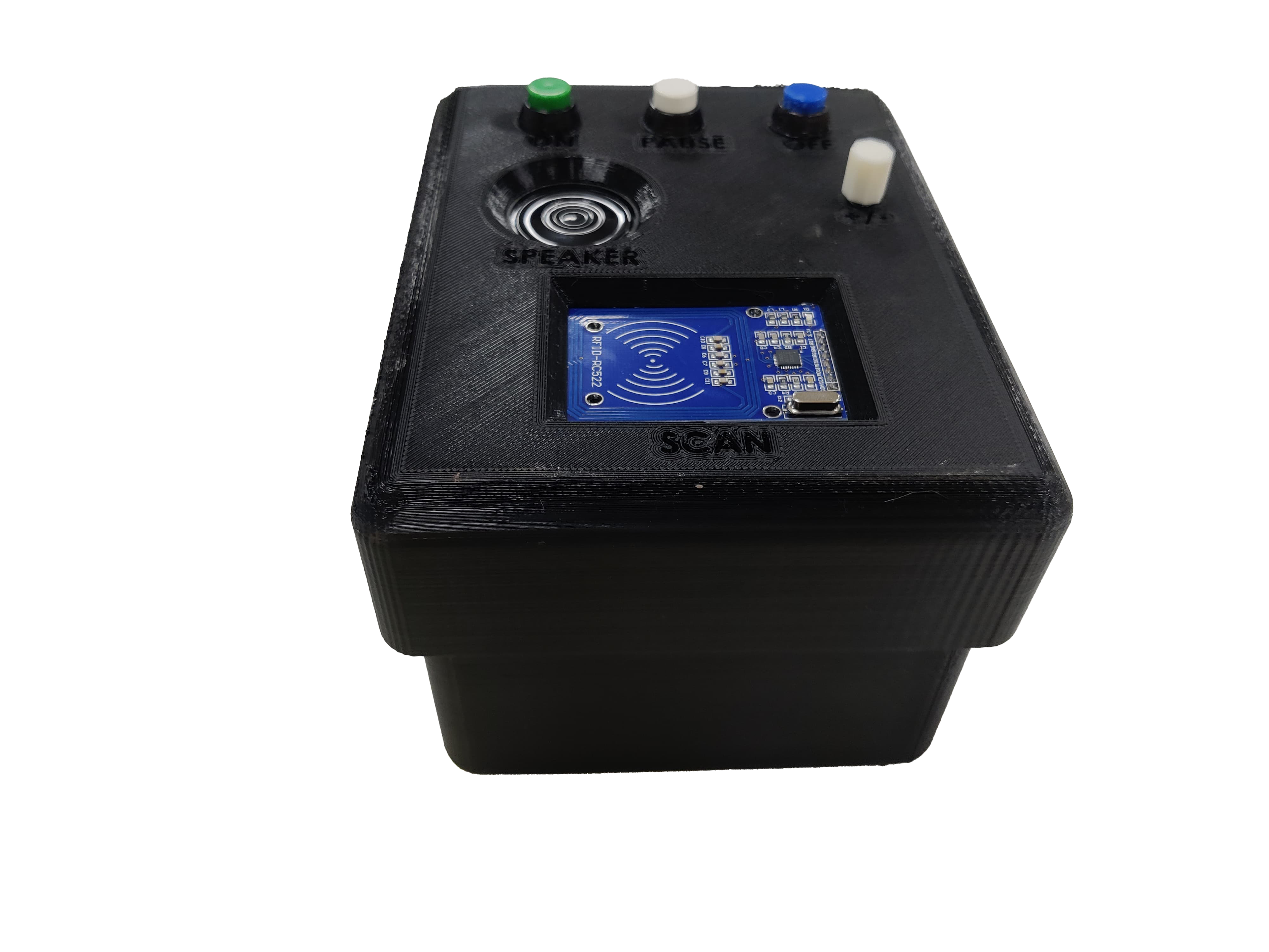
Final Case
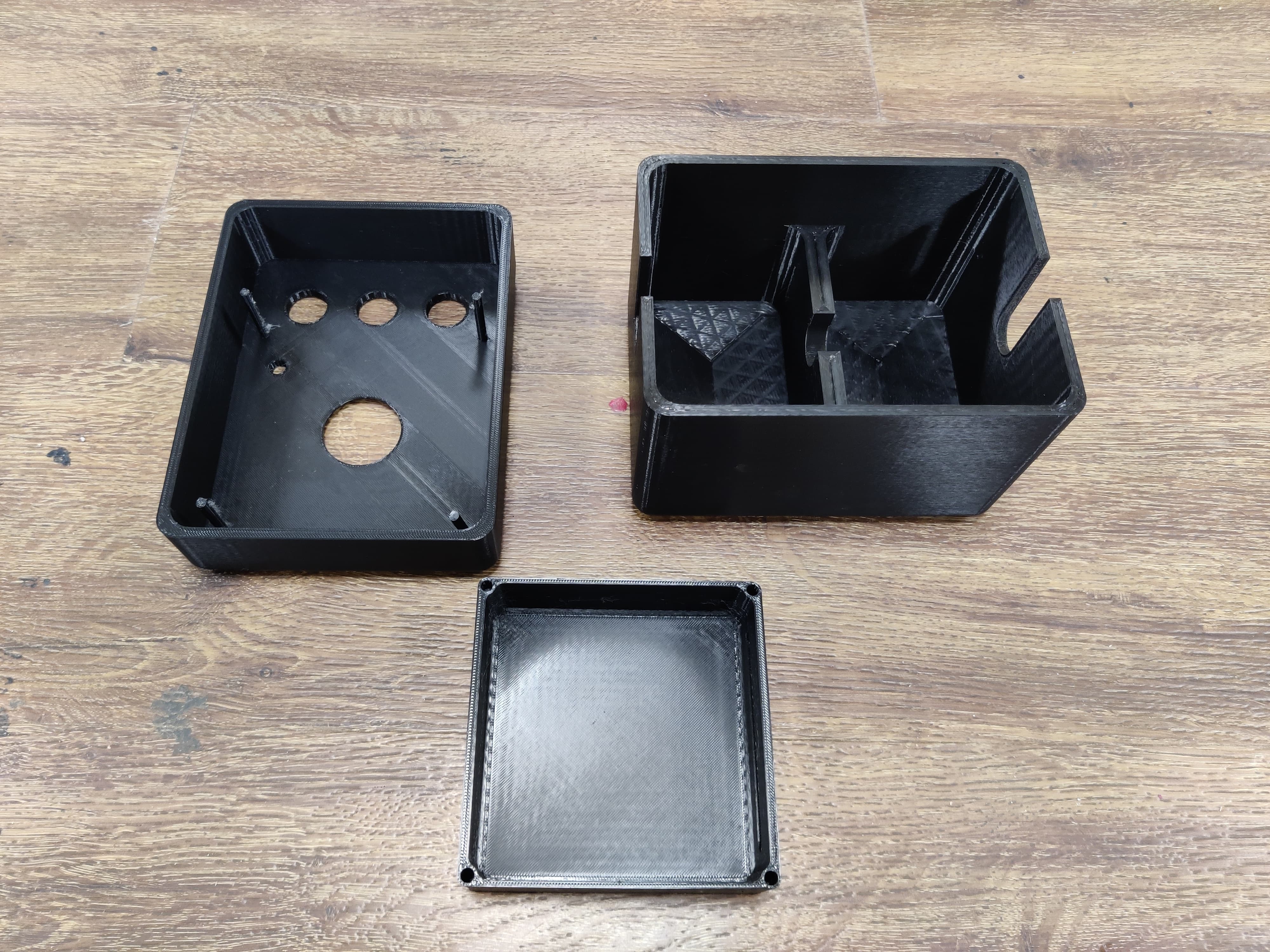
3d printing of the case
Old Case
This was the old case, after presentation I printed a new case.
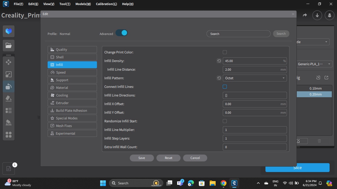
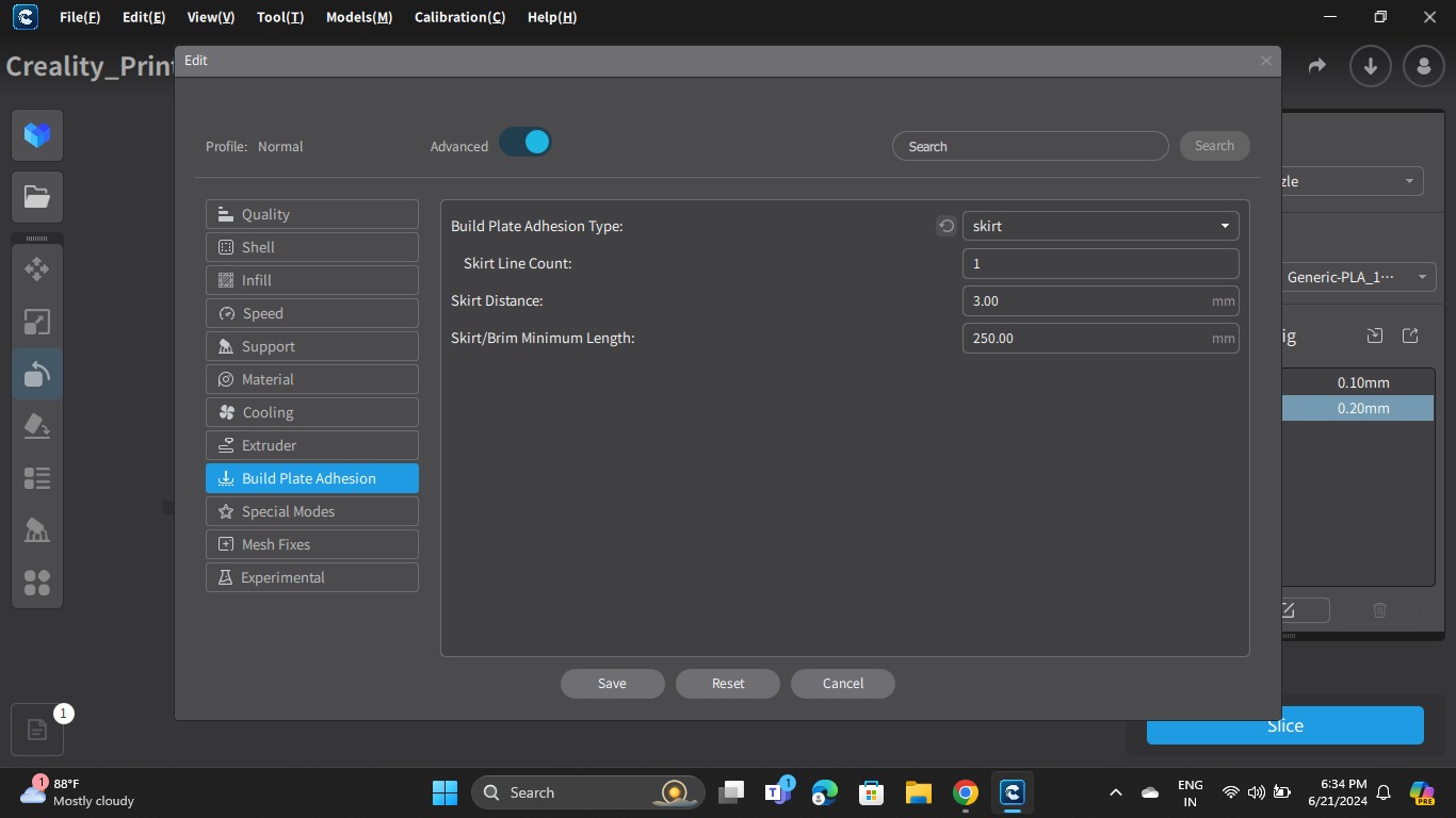
Now it was time to 3d print the files so to 3d print it we need to slice the file and make G-Code of the file, I did that in creality software and the printer which I used was V3 KE printer. The method of slicing remains same in all the softwares, the software depends on the printer which you are using. To know in detail about the printer and how to make g code see Week 5 documentation..
New case
Top box
In the top box I decreased the size of push buttons, speaker, rfid scan box and labelled the buttons and scan me on the box.
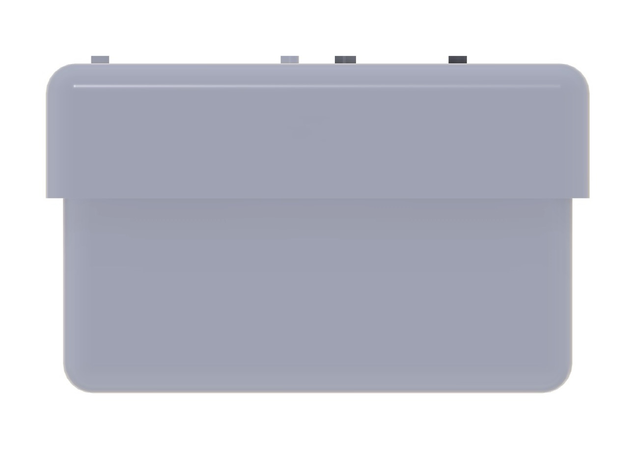
Middle box
In the middle box I increased the size of the hole in which the top box was initially fitting, as it was not fitting perfectly earlier.
Below box
In the below box I decreased the u cut size which previously you could see from sides but now you cannot.
Final case without electronics
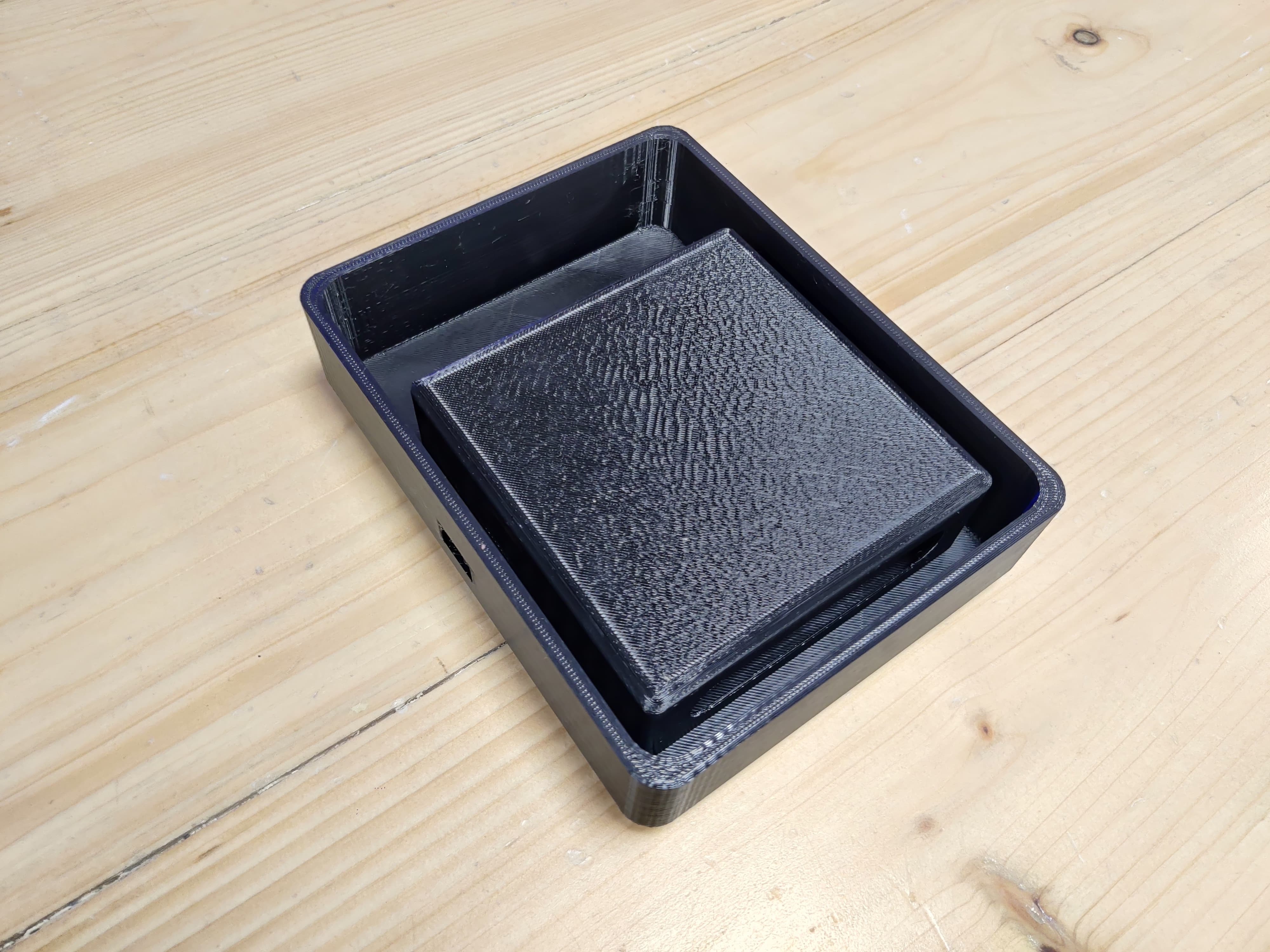
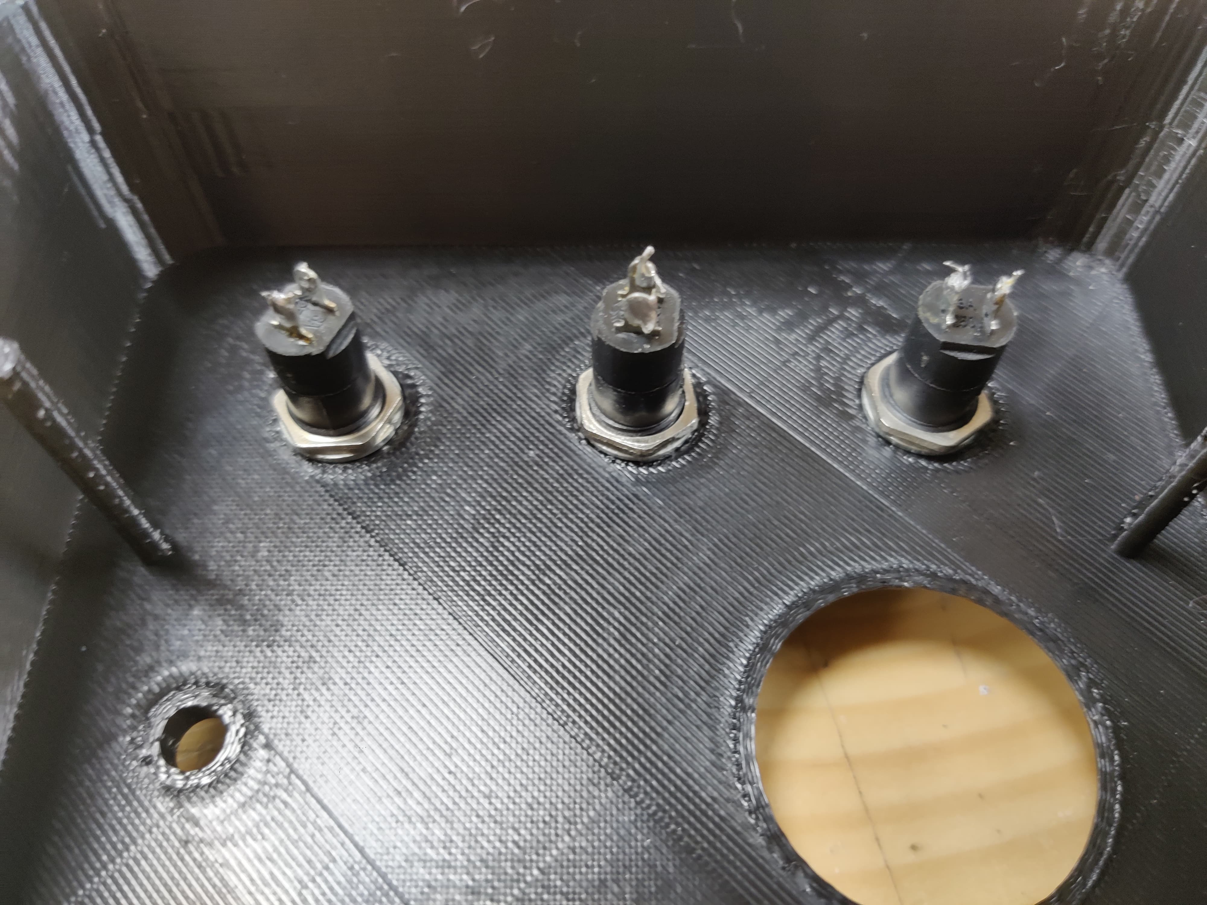
Assembly
This is how my middle part fits into top part and also pcb fits in the middle part.
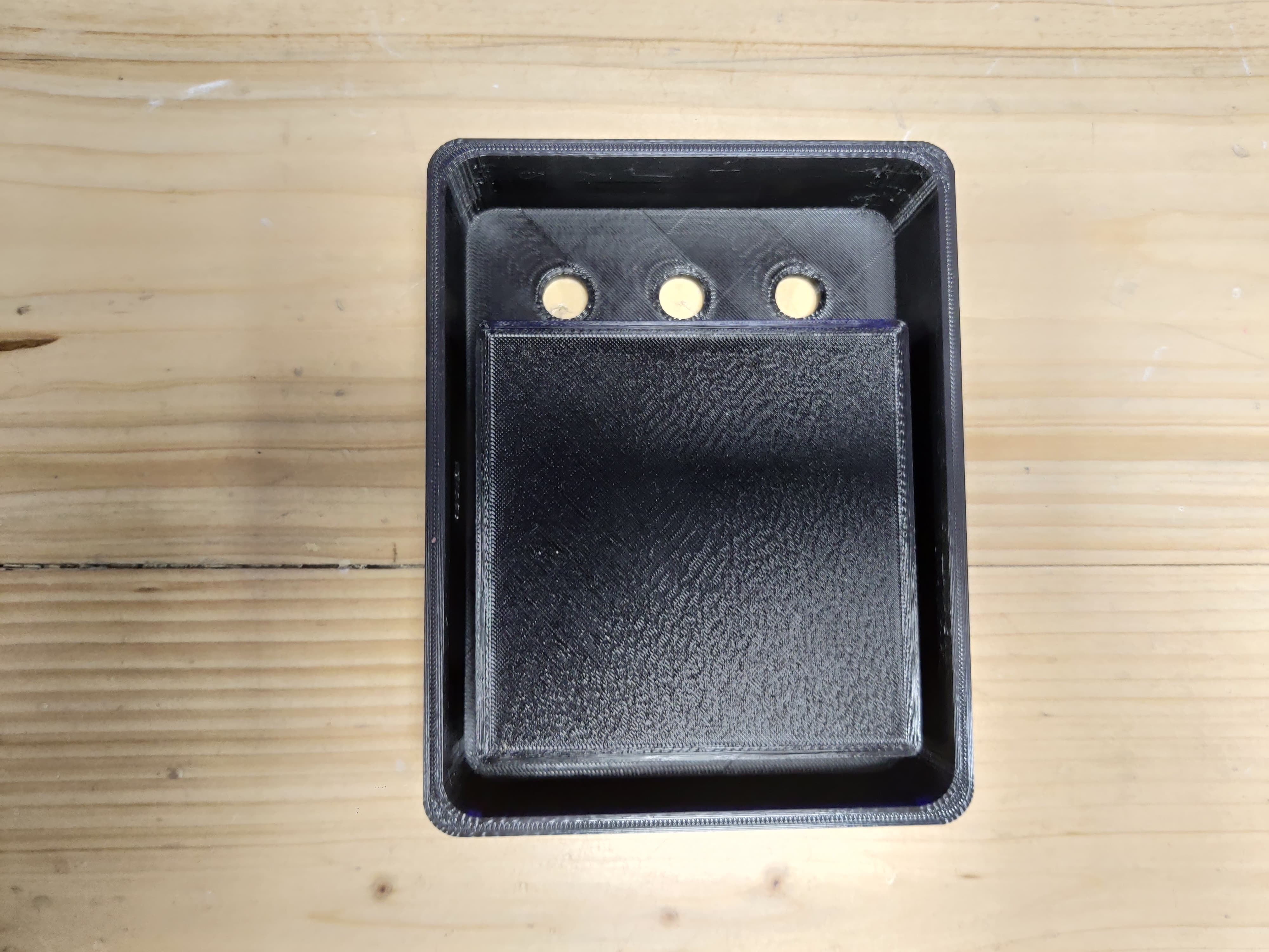
So if you see in the image below this is how push button fix perfectly in the holes now, I have tightened the button with the help of ring which comes with that, also I have put glue gun on all components so that the wiring doesn't interfere or gets removed from the main pcb board.
Final Case with electronics
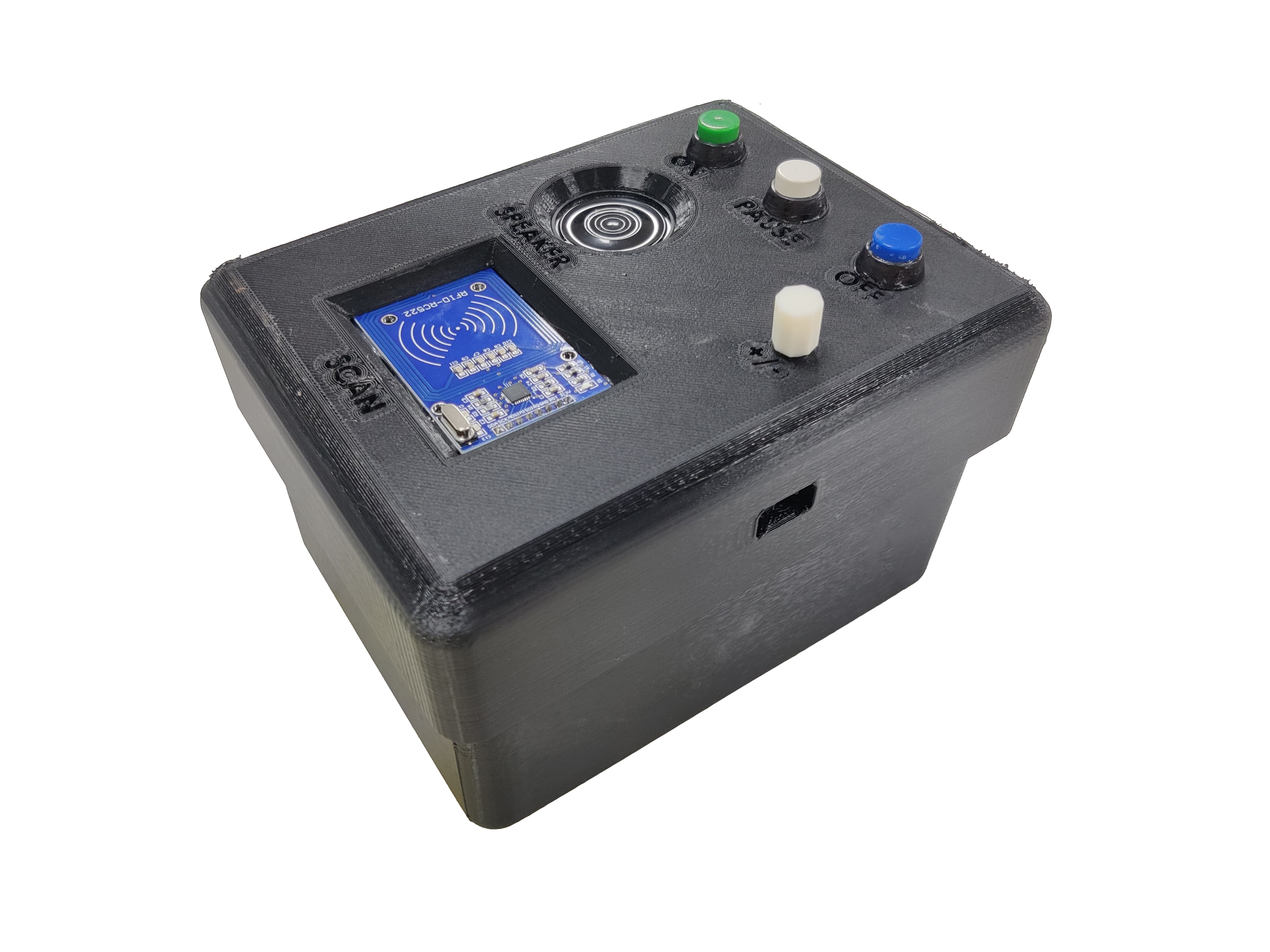
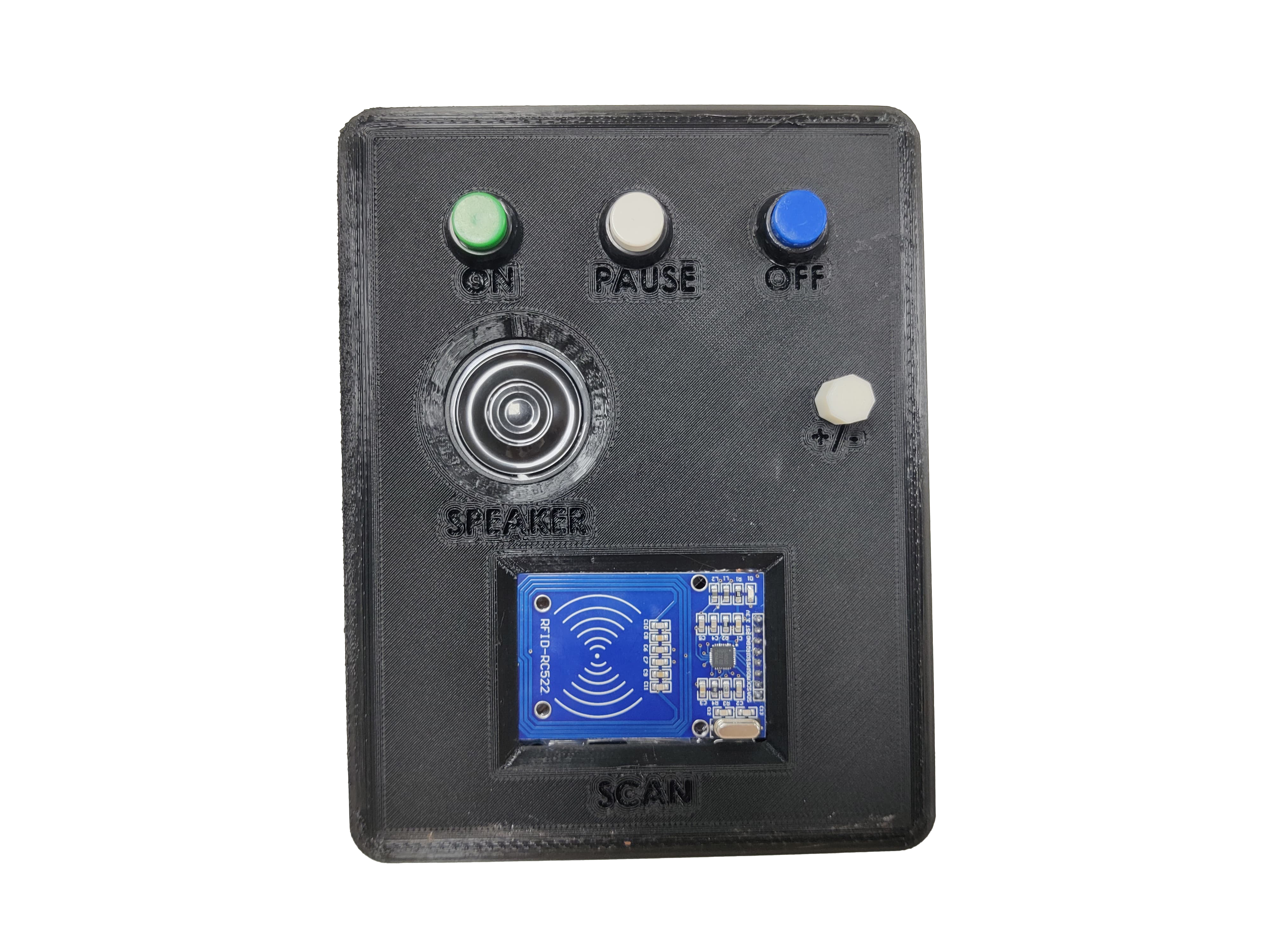
Product Labelling
Working video
Final Video
After this I clicked a new video with all the changes.
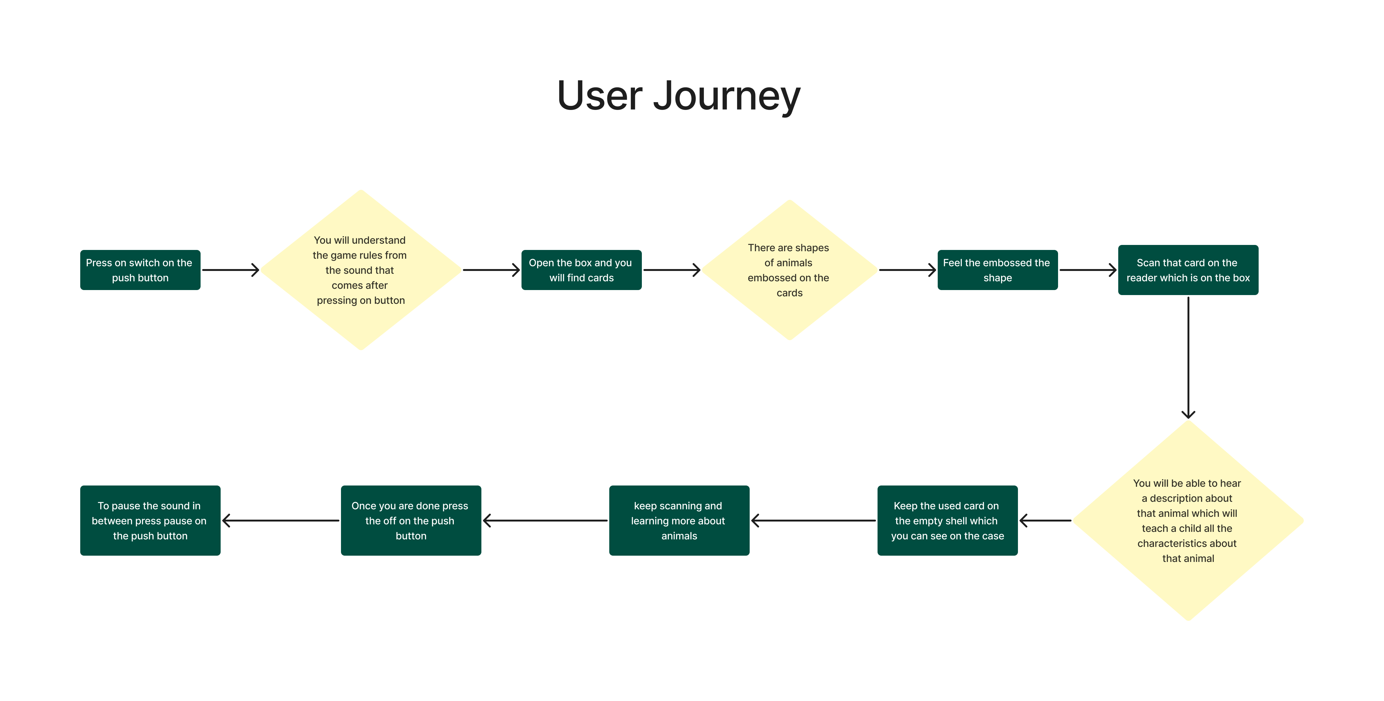
User journey
I have made a user journey of how my product will be used by the user.
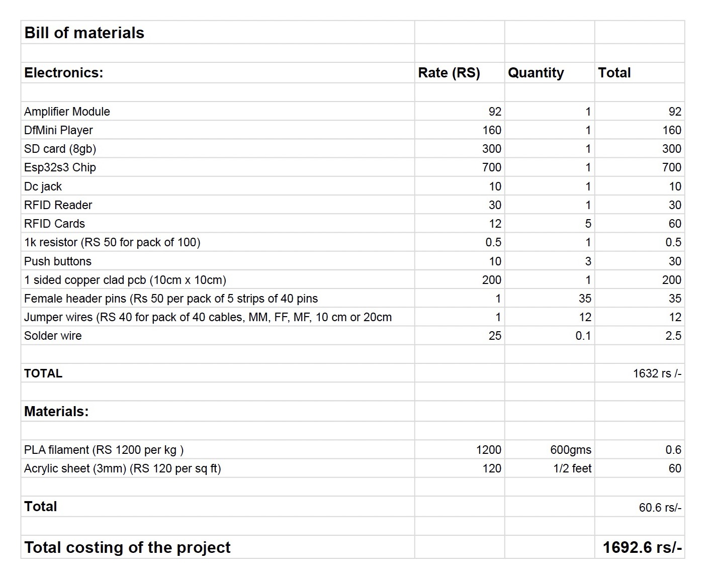
Bill of materials
Download Files from here
All files are there in below zip folder
This files include:
2d cad design ai and dxf File
code
pcb design File
New case stl files
Final Project all files
Previous Ideas
Idea 1
Abalone game-
Abalone is a 2 player game, it had 1 hexagon board on which there are spaced to keep marbles, the reference is shown below -
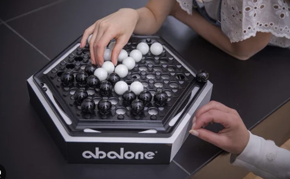
So one player needs to push 3 marbles at a time to kick the opponent's marbles out in the line and the person who knocks all the marbles of the opponent first wins the game. So it has multiple permutations and combinations which cannot be counted. It's like a chain reaction game where anything can happen.
Problem-
The problem with this game is if there is no one to play with you, you can't play such a fun and interesting game. So what can we do?
Solution-
If there is only 1 player then the opposite move is played automatically by the computer but still it is a physical game
The game can be in 2 ways imagine you are alone and your friend is in the USA but still if he wants to play this game, the person in India has a board and it is connected via mobile app and when he plays the move from mobile, the move automatically reflects on the physical board,
Concept 2
There is no mobile and no friend but the move is played automatically on the physical board.
Why am I not going with this idea?
As there are multiple and unpredictable moves every time it will be difficult for me to code as the permutations and combinations cannot be counted and doing it in 5 months is another challenge. I am thinking of taking the same concept and putting it on some smaller game which has limited permutations and combinations.
Idea 2
Timer of chess board on board itself
While playing chess game we need seperate device for the timer, so I was planning to include timer on the board itself so the players are not looking at the side to check the time but the time is on the chess board itself
Why I did not continue with this idea?
I abandoned the idea of integrating a timer directly onto the chess board itself because it could disrupt the traditional gameplay experience, potentially distract players, add unnecessary complexity and cost to the board, offer limited utility compared to dedicated chess clocks, and may not cater to the accessibility needs of all players.
Idea 3
Installation- Voices of diversity
There will be a sculpture of unity or diversity where there is a theme of particular topic for eg say- The favourite story of your culture, now we can tap on any part the sculpture the led lights up and we can record our story. If you want to hear about a story you can again tap on that culture part whoes story you want to hear and you can hear that
So the moto of this installation was to get all cultures together
Idea 4
Smart table for designers
The basic things which one designer always wants around them are pencil, pens, scissor, cutter, cutting board, in short all basic stationery on there table but to keep everything on one table is difficult.
Solution
A foldable smart table where there will be all stationery in different compartments, you can tap any compartment depending on which material you want and that object will pop up
Why I am not doing this idea?
As I mentioned that it will be portable but at the same time it will require electronic connection everytime to use this table, but I did not wanted that
Idea 5
A smart Ruler.
A ruler which will have a normal scale and T scale inbilt, it will be foldable one can use whatever type of scale they want.
There will be a screen where you can change the units of reading like cm, mm, inch, feet and so on.
Then if there is a line already down there it will read and tell you the measurement of that line.
If you want to make a line, for eg:I want a line of 5.6 cm, so what can one do is just manuaaly insert the measurements you want on the device
Features
portable
cost-effective
Dual scale
same transparent scale<
Easy to use