Computer Controlled cutting
The lasercutter is one of my favourite tools in the fablab. I am not so familiar with the one at the RIIDL Fablab, but in the past years I have used others at a different makerspace as well as at my previous workplace extensively.
So this is as good an excuse as any to get to know the RIIDL lasercutter better.
Lasercutter characteristics
Points to test :
- focus
- power x speed settings for select materials
- kerf
- joints and joint clearance
Focus
Everyone around is using 6 mm as a nominal value and thumb rule - sometimes literally (insert pic of measuring by thumb). From experience, I know that the zone of focus is rather forgiving usually, and so this works, but I'd like to define it more precisely.
Years ago, I came up with this little tool to find the zone of focus, as well as to look at defocussed beam diameters.
Focus Calibration Jig on Hackaday
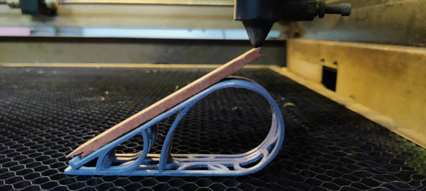
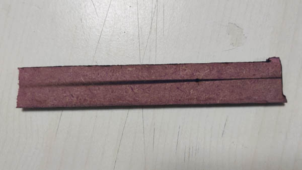
The focus testing jig
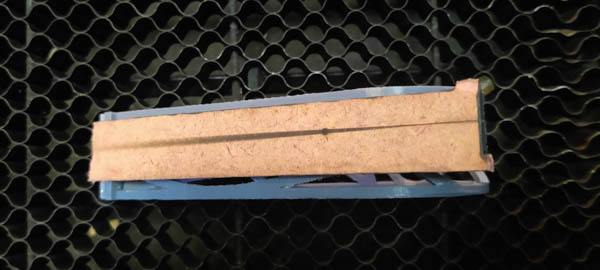
Beam width variation
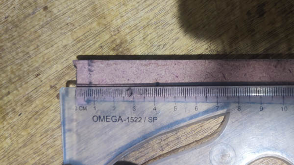
Measuring the focal length
The zone of best focus is at around the 12 mm mark on the scale, so basic trigonometry tells me that focal length beyond the nozzle is 12/2 = 6 mm, with a give or take of 1 mm being ok. (The trigonometry behind the jig is explained in the link.)
Focal Length = 6 mm
Cutting settings
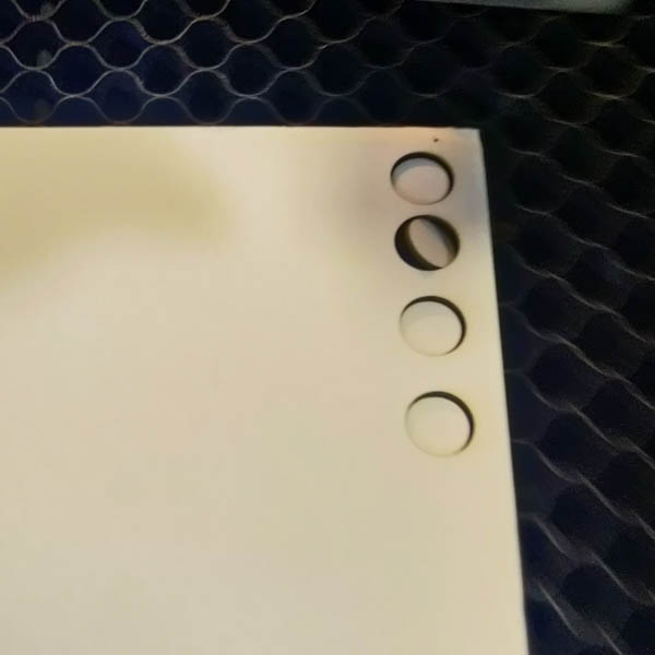
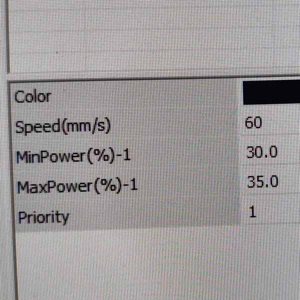
I wanted to test out several kinds of cardpaper we had recently obtained and I was planning to use them for various projects. I figured the cutting parameters for both of them by cutting out a 10 mm circle repeatedly with gradually varying settings. I worked from both directions - starting at lower energy output and increasing power + reducing speed, as well as starting at a high energy output and reducing power + increasing speed, until cuts started or stopped happening.
I personally prefer higher speed while pumping higher power in the interest of saving time, especially when a large quantity of cuts needs to be made.
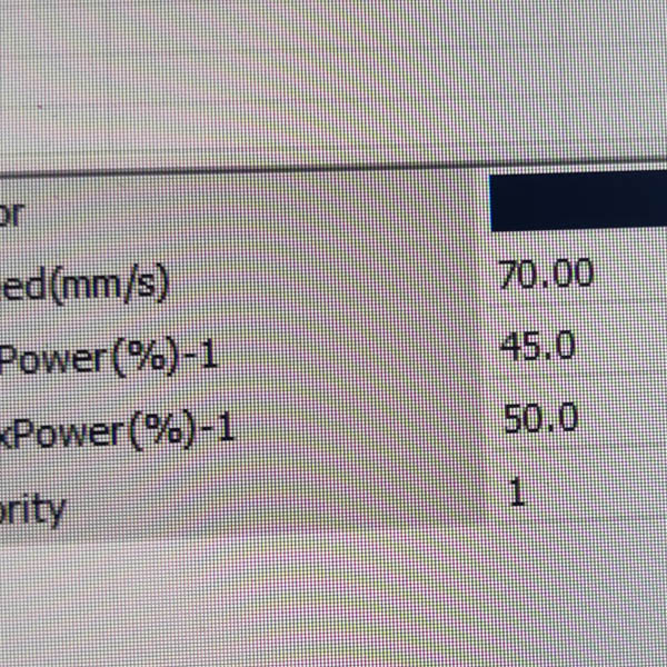
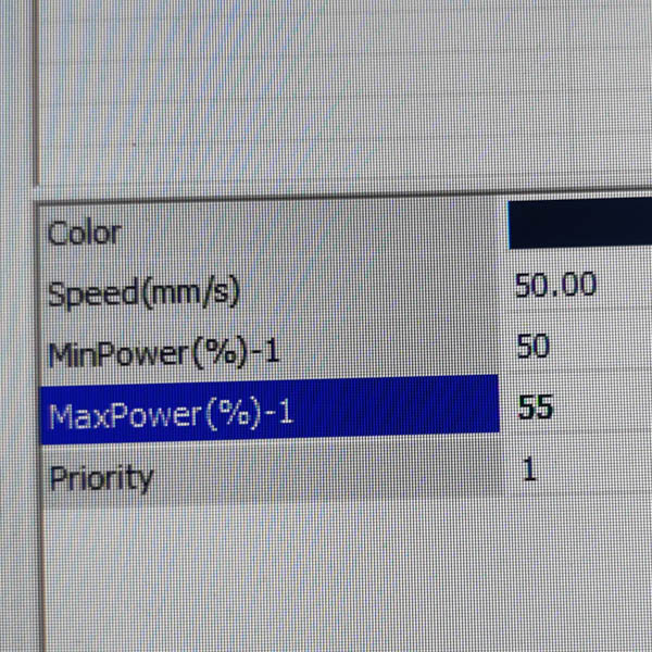
| Material | Speed | Max Power | Min Power |
|---|---|---|---|
| Whiteboard | 70 | 40 | 45 |
| Greyboard | 50 | 50 | 55 |
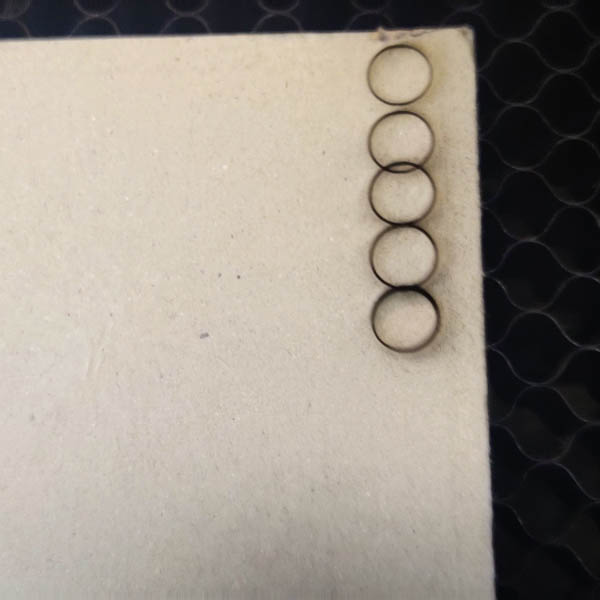
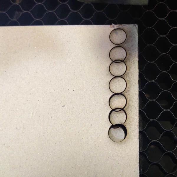
Kerf, joints and joint clearance
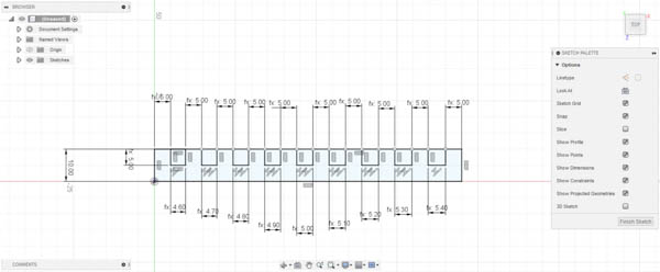
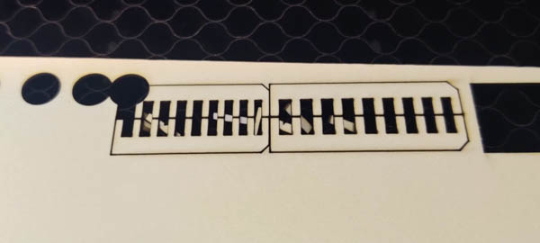
Since I knew I was going to test out a bunch of new materials, I decided to finally create a parametric drawing to be able to export Comb drawing variants quickly.
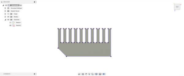
In Fusion 360, I defined 2 User parameters - nominal thickness and incremental difference. Nominal thickness would be the approximate/guessed/measured thickness of the material, and the incremental difference would be the step size difference between subsequent teeth. The centre slot of the Comb was defined as the nominal base thickness, and slots to the left had the step size subtracted from them, while slots to the right had them added. To avoid confusion as to which end was which, the piece was given a chamfer on the left end.
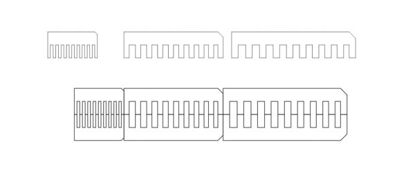
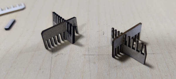
While defining the parametric drawing took time once, I have been able to use it to quickly generate multiple combs of varying thickness and step sizes for a range of materials. It has also enabled me to forego using Vernier Calipers on occasions when I don't have access to them, by simply making a comb with a guessed thickness and larger steps and then a second, finer one based on the results of the previous one.
To note, the Comb test gives a resultant dimension that accounts for both, material thickness as well as kerf loss. However, this is convenient enough when designing because it will tell you exactly what dimension will work effectively for your joints, rather than having to offset post-fact. I suspect there may be some purist alarms against this, but given the wide variance and deviation from standard in the materials available around me, I much prefer this method.
Another thing I have picked up from experience is that the kerf loss and the joint tolerance tend to be about the same. In other words, countering kerf loss and increasing dimensions to be true and exact would not allow the joint parts to mate easily, whereas allowing kerf loss makes mating joints a snug fit. The caveat, of course, is that this is true for the materials I usually work with and the machines I usually work with, so YMMV, as may mine given a different standard of material or machine.
This is not to deny that kerf should be known on its own, to be sure; always helps to know your machine and material better. But these are just thumb-rules that save time or help convenience.
Files
Comb Test parametric fusion file
Comb test files (slot testing)