Output Devices
Lights, shiny lights !
I have always been fascinated with lights and lighting, and associated fields. Photography, optics, telescopes, mirrors, light painting, shadow boxes - all are fair game. So it was natural that I tried to control lighting as an output for this exercise.
NeoPixels
NeoPixels are AMAZING. All the convenience of an LED light, but can change colour, and can be controlled since they are addressable. What's not to like ! It helped that I already had several modules in stock to play with, so didn't have to wait for the deliveries to arrive.
My first stop was the Adafruit site, which is an amazing resource for all things NeoPixel. I had gone through this page at length earlier as well (when I was playing with the Neos on an Uno) but I keep visiting it - especially the Power Guide and other Best Practices.
Powering NeoPixels
NeoPixel Best Practices
According to the Power Guide section on Estimating Power Requirements,
at full brightness - 1 Neopixel draws 60 mA
on an average or for 1 single colour - 1 NeoPixel draws 20 mA
Most of my modules are 16 NeoPixels in size (square or ring or strip) so for my applications,
16 x 60 = 960 mA = 0.96 A
16 x 20 = 320 mA = 0.32 A
0.96 A is near but within most chips' limit to supply, and 0.3 A - 0.6A is a fair supply. So most of my modules, especially if not at full-white, are fine running directly off the MCU.
Two more points that need to be made (and that the page screams at you before you can proceed)
- connect GND before all else, every time
- a 300-500 Ohm resistor ahead of the Din pin on the first Neo, for safety reasons. I've had first pixels go off showing an entirely different colour after a while. I did not wait for this to become irreversible and added the resistor immediately.
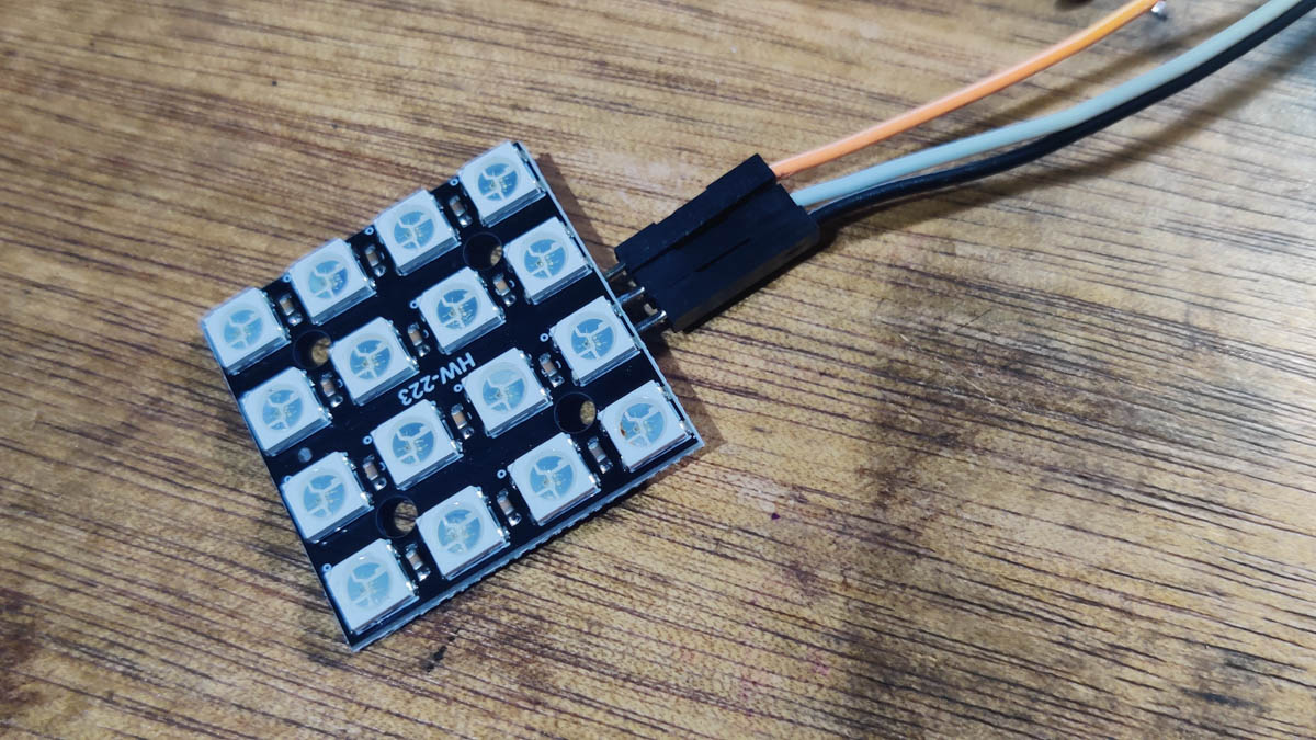
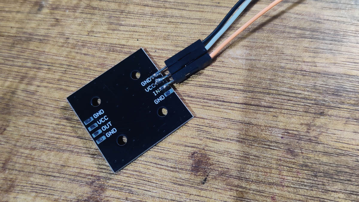 I soldered 3 jumpers to the 3 solder pads on the Square module for convenience.
I initially ran them off an Uno and breadboard before trying them with the XIAO and devboard. The miniature breadboard holds a 370 Ohm resistor to safeguard the Din pin.
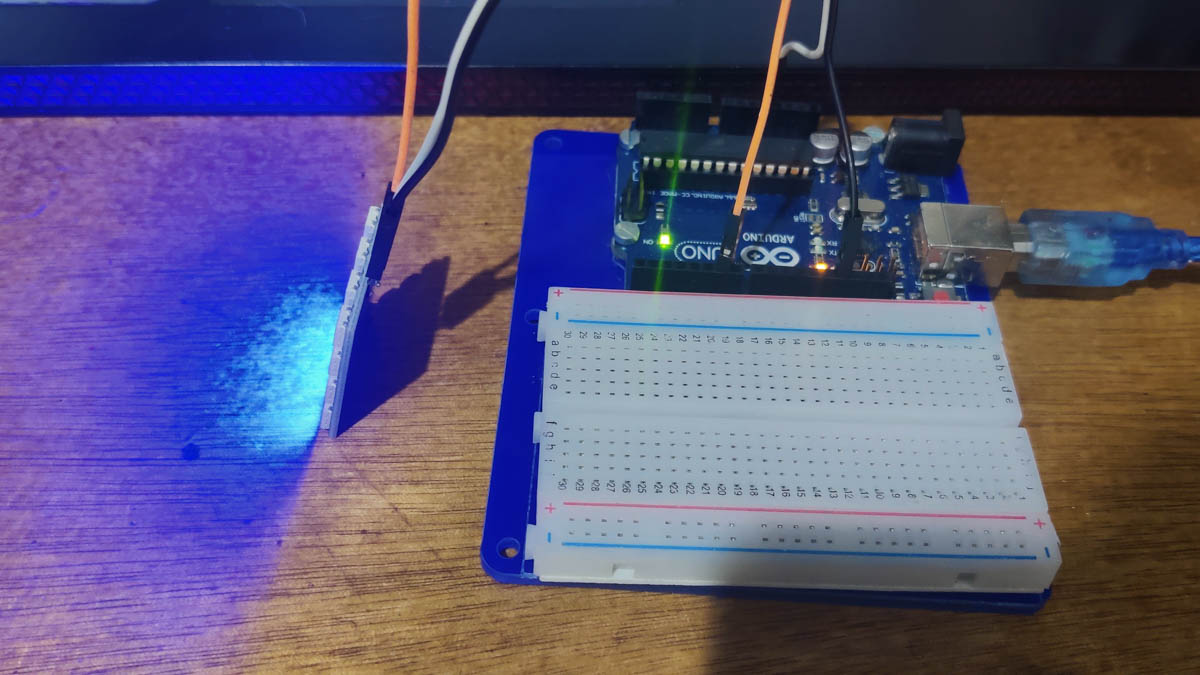
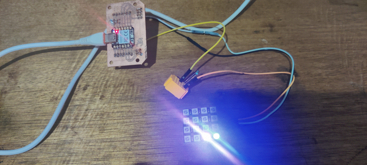 random colours, XIAO PCB
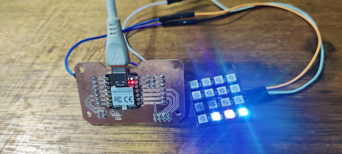 random colours, XIAO PCB (newer version)
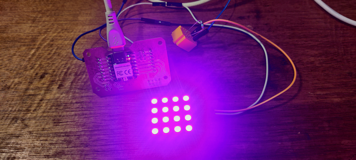 full colours for strobe effect, XIAO PCB (newer version)
My code makes the entire panel flash different hues at maximum brightness.
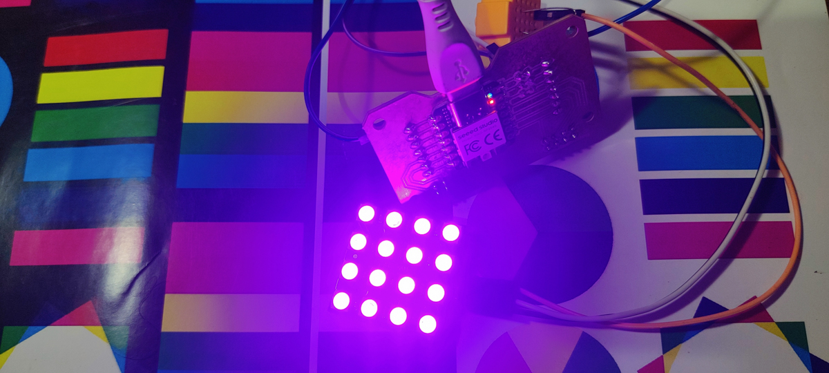
At a recent party, I noticed that coloured strobe lights were highlighting different colours on peoples' clothes, etc - additive colours (lighting) meeting subtractive colours (print). I wanted to use this effect to try "animate" on a static printed medium. So I've printed out a test page with various shapes - bars, squares, circles, etc - to see how far I can make this work. The results are definitely interesting and I will pick this up to follow once the rest of my Fab commitments are done.
Hero Shots
Electro-Luminescent Wire
Being a lighting enthusiast, I had collected some EL wire as well at some point.
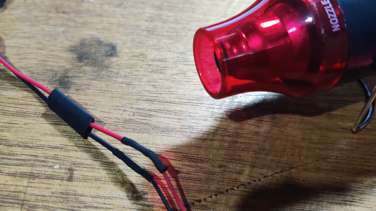
But first I had to clean up the terminals on my EL wires. A couple had just corroded somewhat and needed snipping, stripping, retinning, and another few had a connector that I didn't have a mate for, so I lopped them all off, soldered DC barrel jacks everywhere and covered everything with fresh heat-shrink tubing.
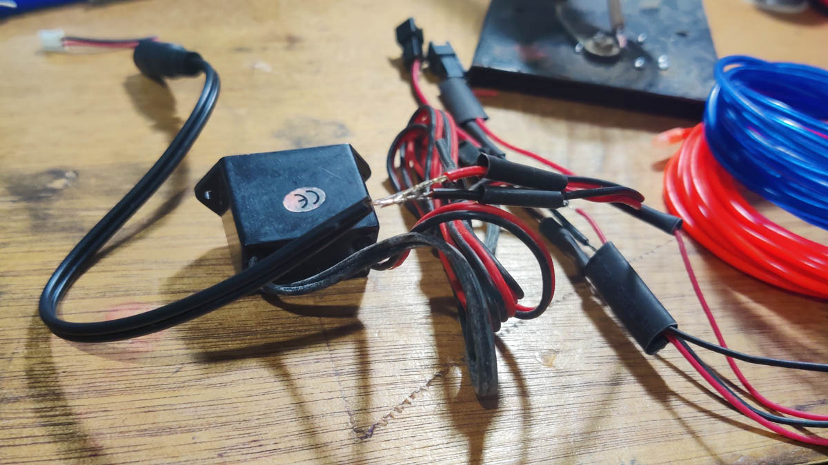
Using the MOSFET
Unlike LEDs or NeoPixels, I need an external source to power them. Infact they come with a dedicated power converter. While earlier I had used relays to control such applications, this was a slightly annoying method because of the noise and a limit on fast switching.
The Fab deepdive into Electronics made me a little braver, and I decided to finally try these MOSFET things that I had been hearing so much about. Not knowing what model to actually pick up, I played safe and found some Arduino-compatible MOSFET modules and promptly ordered them.
Later I looked up the datasheet for these, as well as spent some time understanding the various parameters (Gate Voltages and suchlike) to order the slightly less expensive and considerably less bulky standalone components.
Using a MOSFET with an Arduino
IRF520 MOSFET module
Datasheet for the IRF520
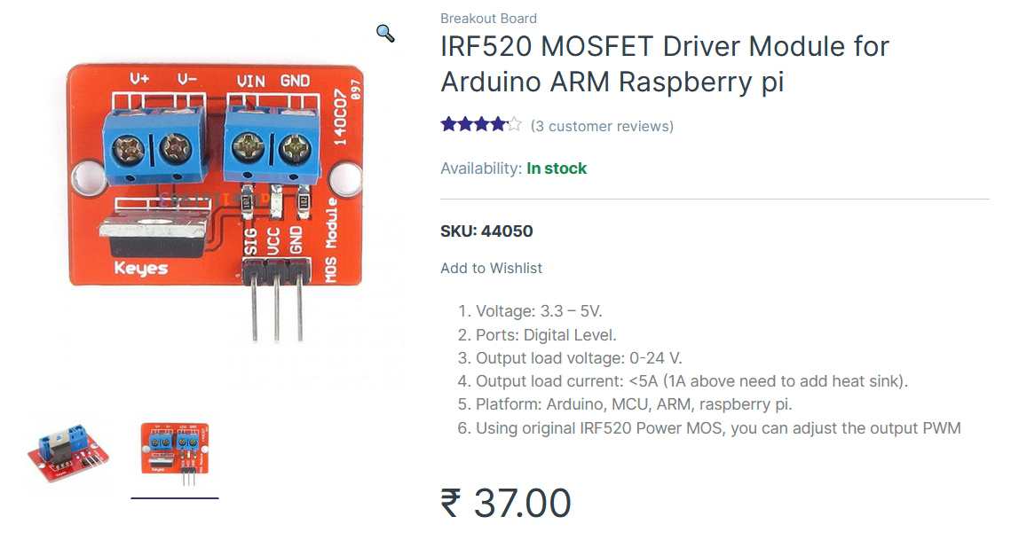

The Robu page for the IRF520 MOSFET module had a fairly straightforward instruction set, and the module itself makes everything very clear. I also found a project page to guide me, although it wasn't really needed after all.
I made the EL wore work for with an Uno.
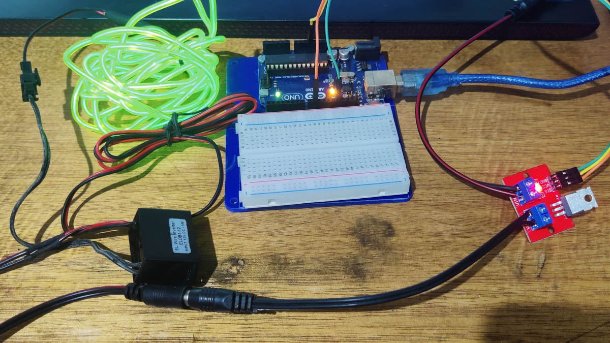
However, on trying it with the RP2040, I haven't been able to make it work. The MOSFET module isn't triggering at all. The DataSheet for the IRF520 states that V(GS) = 2 V (min) - 4 V (max), so the RP2040 at 3.3 V should still be able to trigger it.
One possibility is that the "module" version has built in resistors (there are definitely some visible) since the Arduino's 5 V needs to be turned into a more suitable 3ish, but this is now dropping the RP2040's 3.3 below the acceptable limit. I should simply use the bare MOSFET instead of the module, in that case. I'll put it n the To-Do List. Access to an oscilloscope would also be nice, so I'll check out if there's one in the lab.
Exercise files
RP2040_NeoSquare.ino - random colours
RP2040_NeoSquare_Anim.ino - strobe colours for animation
RP2040_ELWire.ino