Computer Controlled Machining
This is a really exciting week, for we get to Build. Something. Big. on the CNC router.
I have been doing lasercutting for quite a few years now, and some of the limitations I frequently come up against are
- thickness of material (usually 5-8 mm)
- type of material (not all materials can be lasercut - fumes, fire, etc)
- through-cuts only; no option for half-depth cuts for better finish on slots, etc
- bed size limits (450x600mm - 1200x900mm)
The exciting part is that the CNC Shopbot manages to get beyond all these limitations. It can also do 3D milling, so it is effectively the subtractive equivalent of 3D printing - opening up the ability to mill out 3D forms and shapes.
For all these benefits, it has a few caveats. Unlike the lasercutter with a fine beam of light and an airstream doing the work, the CNC has an actual rotary bit, and this has several physical implications.
- a large kerf, in the range of 3mm-6mm depending on the bit, needs to be accounted for
- internal corners would either suffer to have a fillet the same as the bit radius, or a detente/relief would have to be left to accommodate flush fits
- no common edges between pieces (1 cut for pieces on both sides of the line no longer possible)
- bigger margins around pieces
- a significant margin around the material for clamping
- a significant amount of dust and chips
These aren't necessarily a bad deal, given the benefits listed above. Only things to bear in mind if one is, like me, coming with a significant experience of lasercutting.
The CNC Router
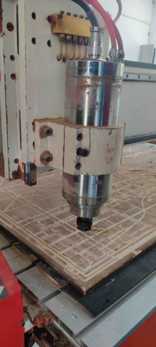
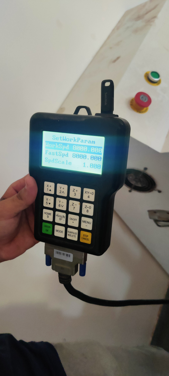
The machine we have is a Numac Hitech machine with a full sized 8' x 4' i.e. 2400 mm x 1200 mm bed size, able to accommodate the standard full size sheets available here.
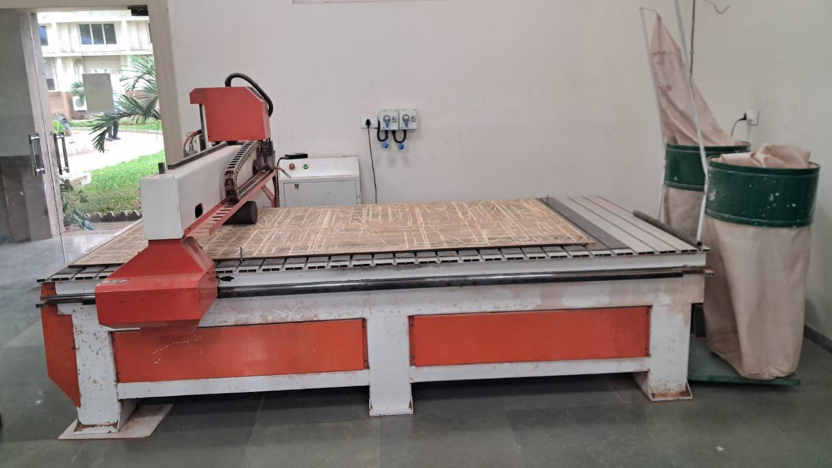
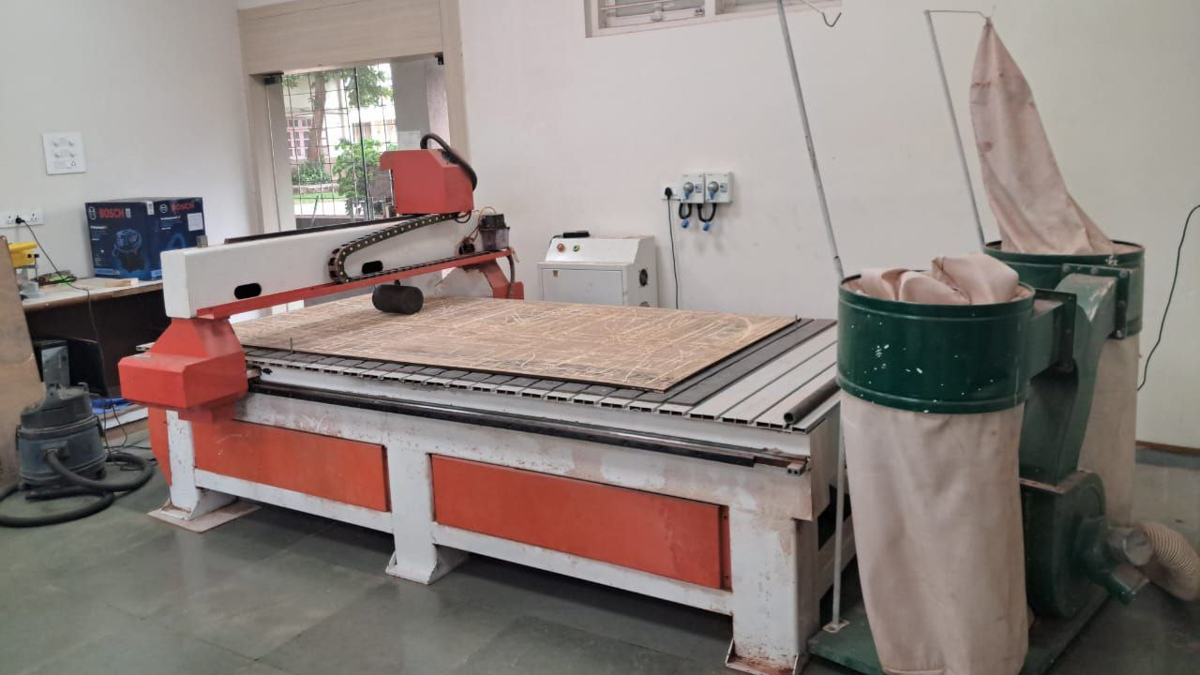
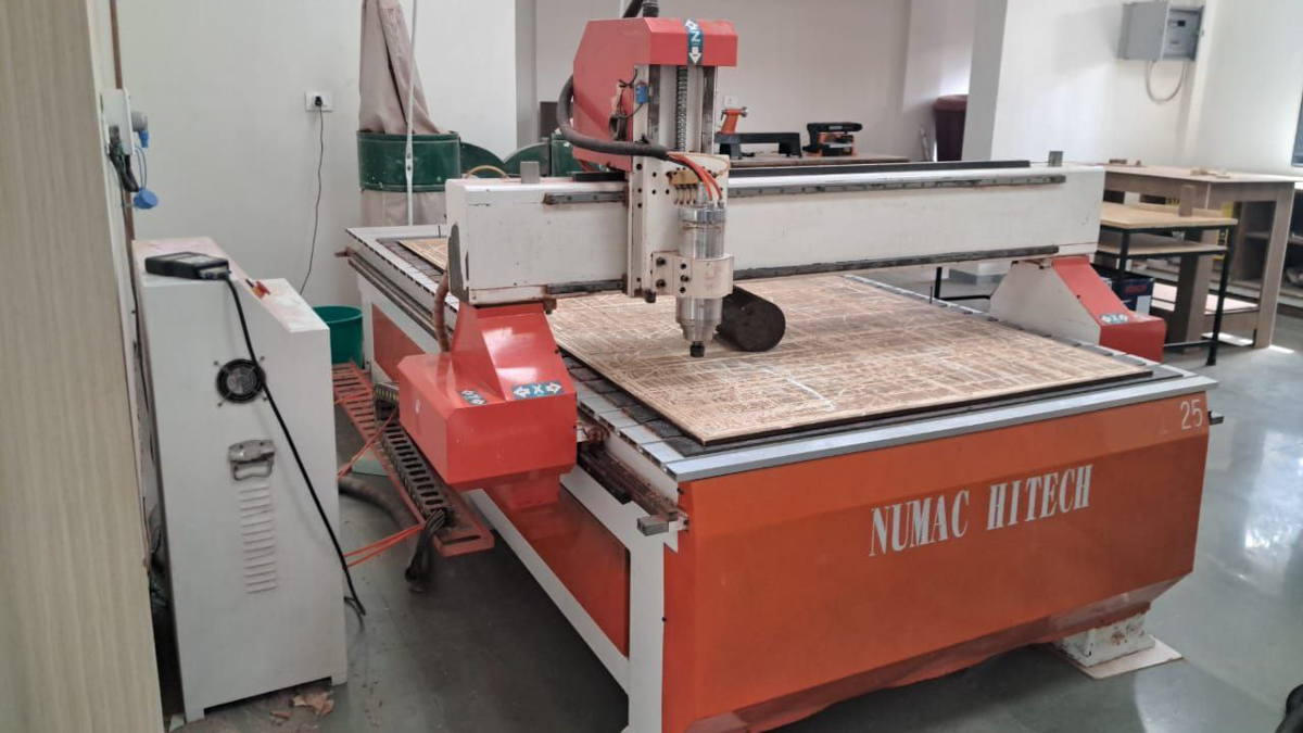
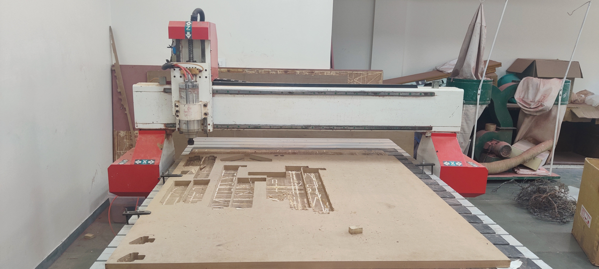
The spindle and the controller
The Exercise
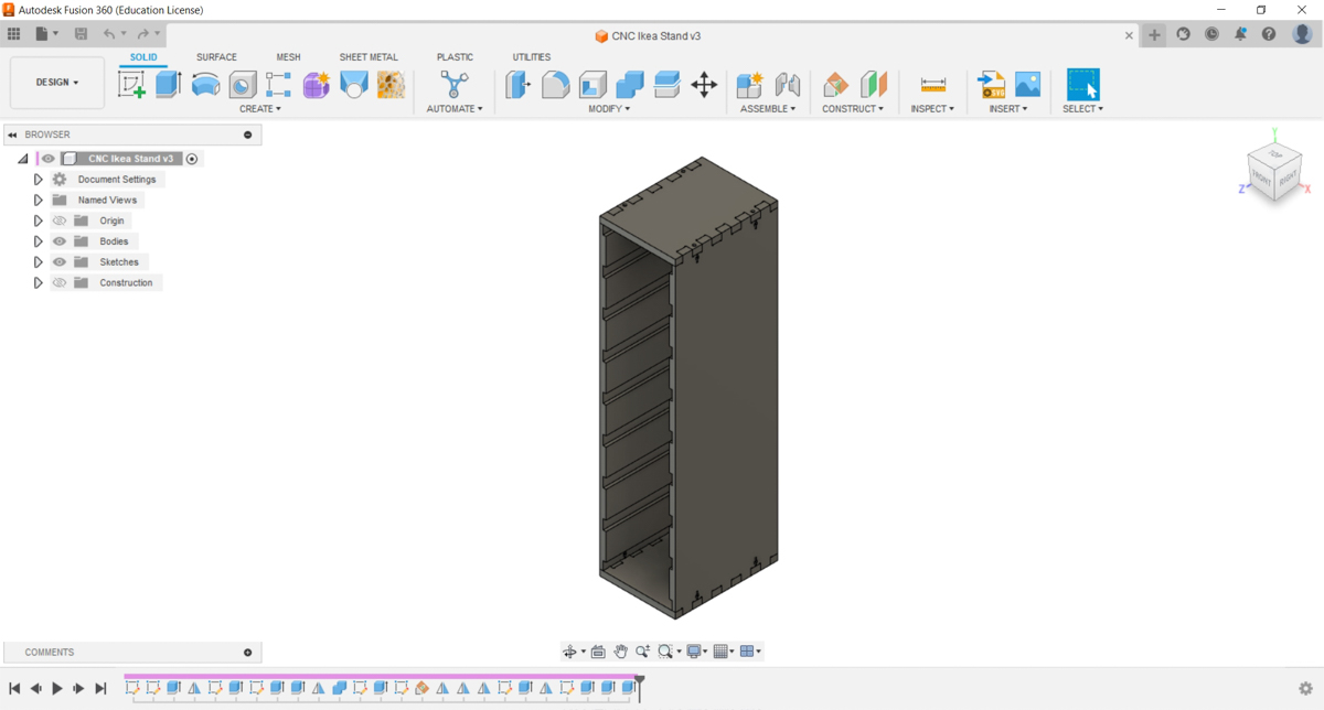
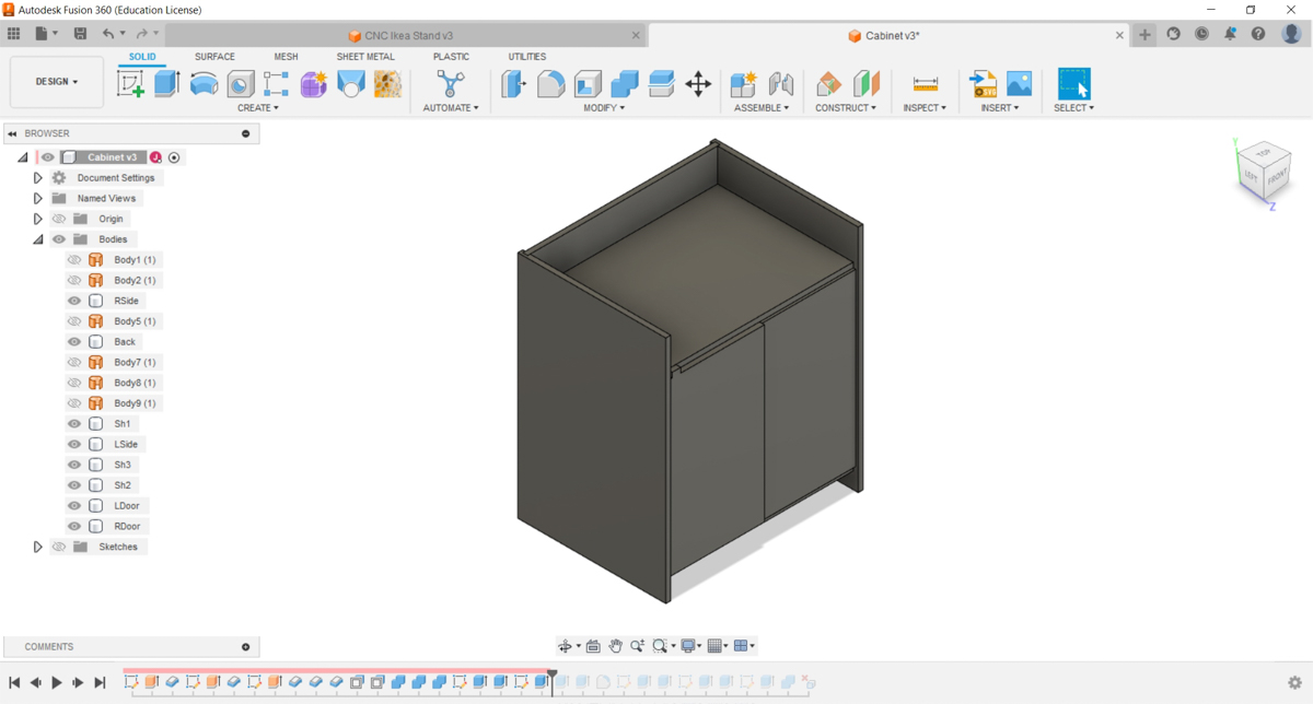
I had planned on building several large storage objects - a set of slotted-fit shelves, a small cabinet with inbuilt hinges, a table, and more. We desperately need the storage in the labs - for books, equipment, boxes of stuff - so I had decided to utilise this assignment to attend to that. While I will eventually get those done, currently, in the interests of time, both mine and the machine's, I am limiting myself to 1 object.
The Oloid
The machine we have at the lab has been under a lot of maintenance and we still haven't been able to connect the dust collector because the converter part is no longer available, apparently. We're working on a 3D printed version of that, but I don't want to run the machine without the dust-collector being operational, since, apart from all the other hazards and issues, it simply trashes up the entire room. So I ran air-trials on the machine in the lab, but I did the actual cutting at a nearby facility that I had access to. Unfortunately, this was limited access so I did a few quick cuts instead of the elaborate cabinetry I had planned.
I am fascinated with rolling objects. (See my CAD and 3D Printing pages for Sphericons and the Anti-Oloid). So, along similar lines, I decided to make a large rolling Oloid, from 18 mm MDF. It would be an interesting object, rolling it's wobbly path around the room or along a long corridor. I was also wondering if I could turn it into a oversize cat-toy, or would my cats simply freak out and avoid it.
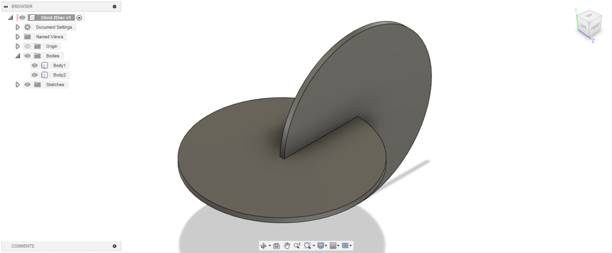
While an Oloid is a 3D shape, it can be approximated very well by two circular discs slotted into each other at right angles. So I drew out the parts in Fusion, including reliefs for the 6 mm bit that would be used at the internal corners.
The DXF was exported from Fusion, and into ArtCAM (yes, Autodesk no longer supports it, but there's a copy floating about on one machine) and from there to the machine.
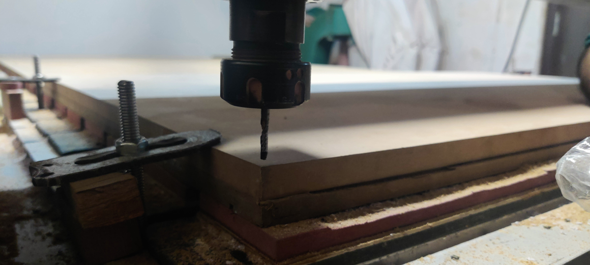
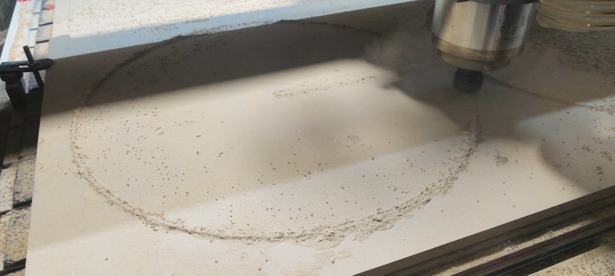
I had designed for 18 mm material, so a 1200mm x 600mm sheet of 18 mm MDF was clamped down onto the bed. We used a 6 mm endmill bit to do the cutting.
After an air-cut to make sure of everything, the Z height was readjusted and we went for the final cut. The cut was simple and quick (and comparing to the lasercutter again, equally fast actually, but at 3x the material thickness!) and I got my pieces out. It took about 3 passes.
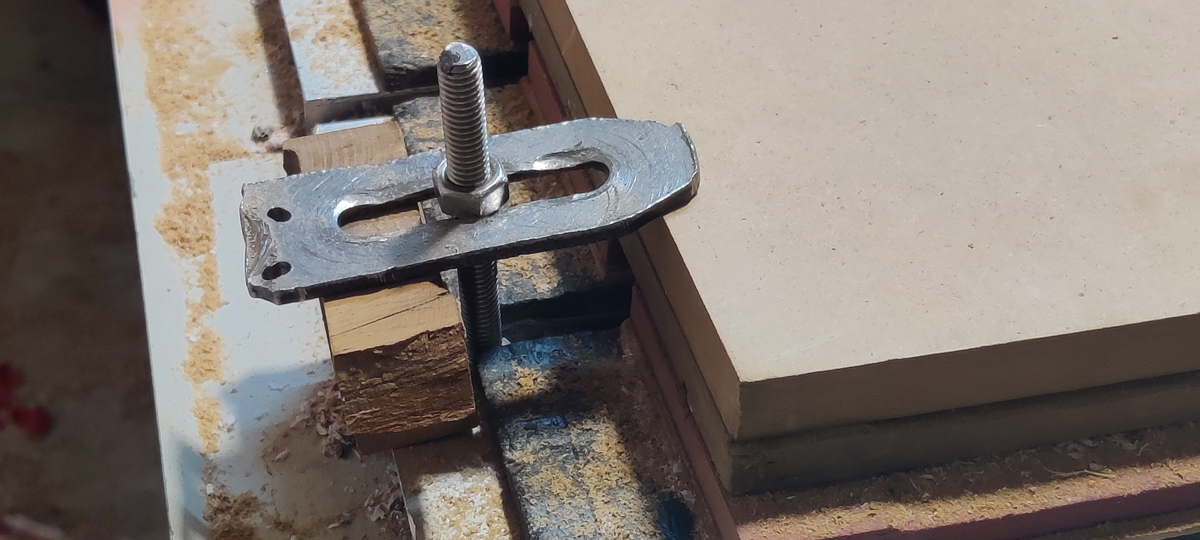
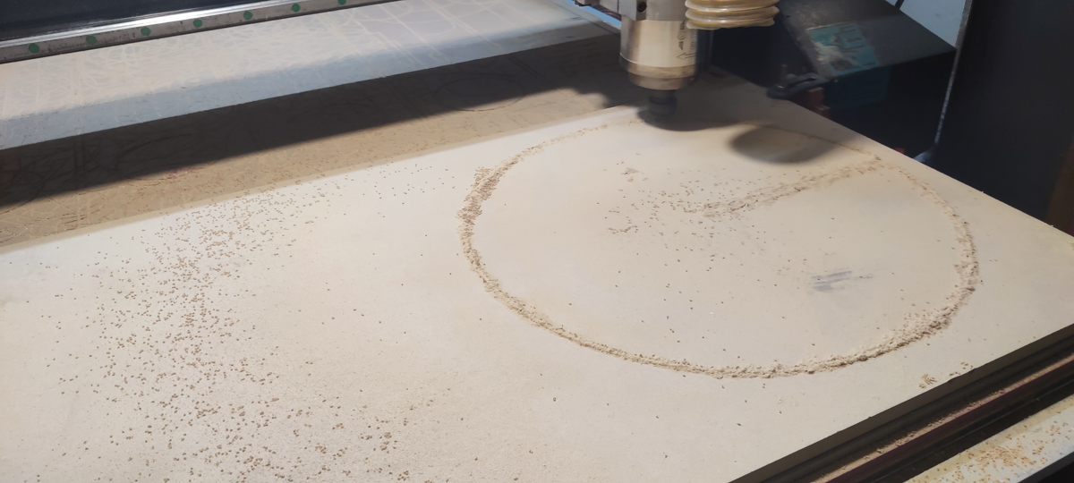
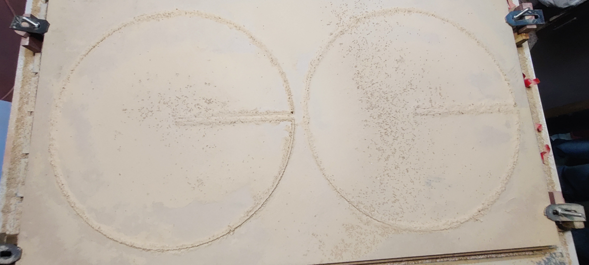
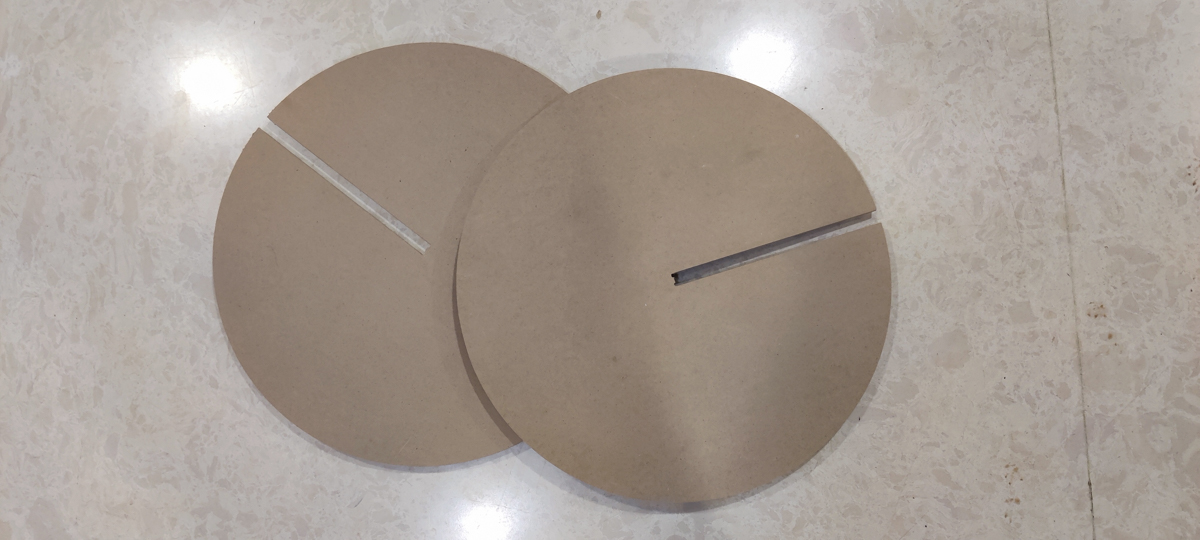 Once the material was unclamped, I ran a quick sandpaper round on the edges to clean them up, and checked the slot-fitting of the pieces together. A perfect fit.
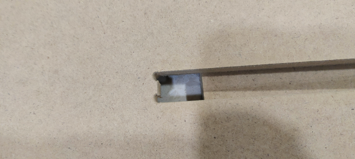 I had left clearance for the 6 mm diameter of the endmill since I needed a perfect centre-to-centre flush fit.
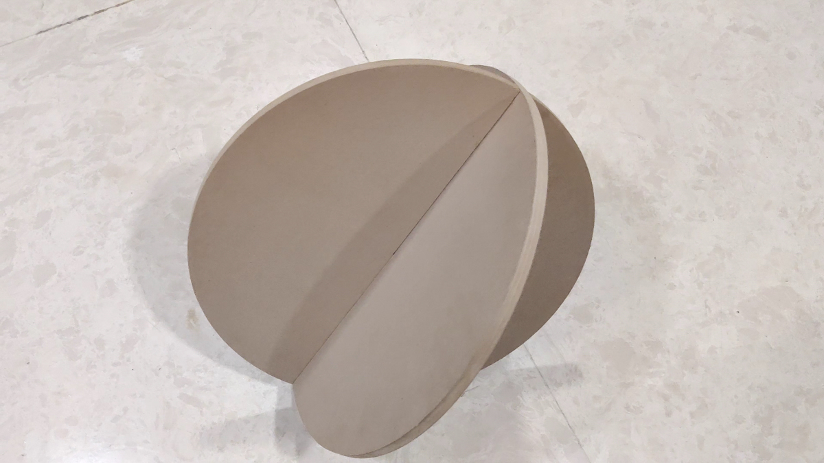 This spherical assembly is not what was intended but is also interesting
Unfortunately, I realised much later that I had gotten the geometry slightly incorrect, so I just cut a small lasercut spacer to right it; the issue was easily correctable. But it did bring home the point that one should make scale models and trials of things before the final version. I had scale models of the other plans, but this one was a quick job and I decided to skip it, and made the mistake I did. Anyway, as I said, correctable.
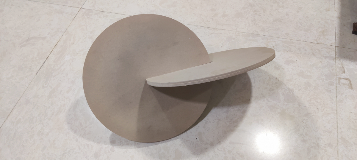 The corrected final assembly

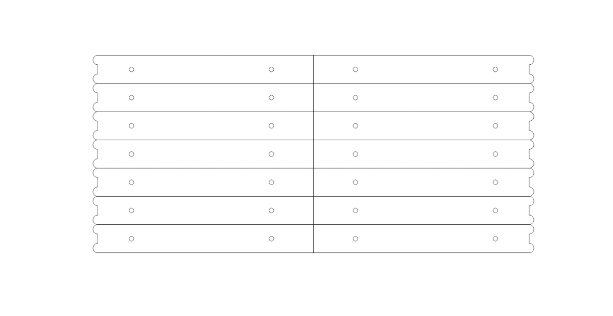
Line drawings of the main pieces as well as the spacers