8. Electronics Design
Hero shot
Group assignment
We were asked to observe the operation of a microcontroller circuit board.
For that, we used our Quentorres + our "blink" Arduino code + an Arduino "fade" code and we checked the measurements with our RIGOL DS1054 oscilloscope.
RIGOL DS1054 oscilloscope
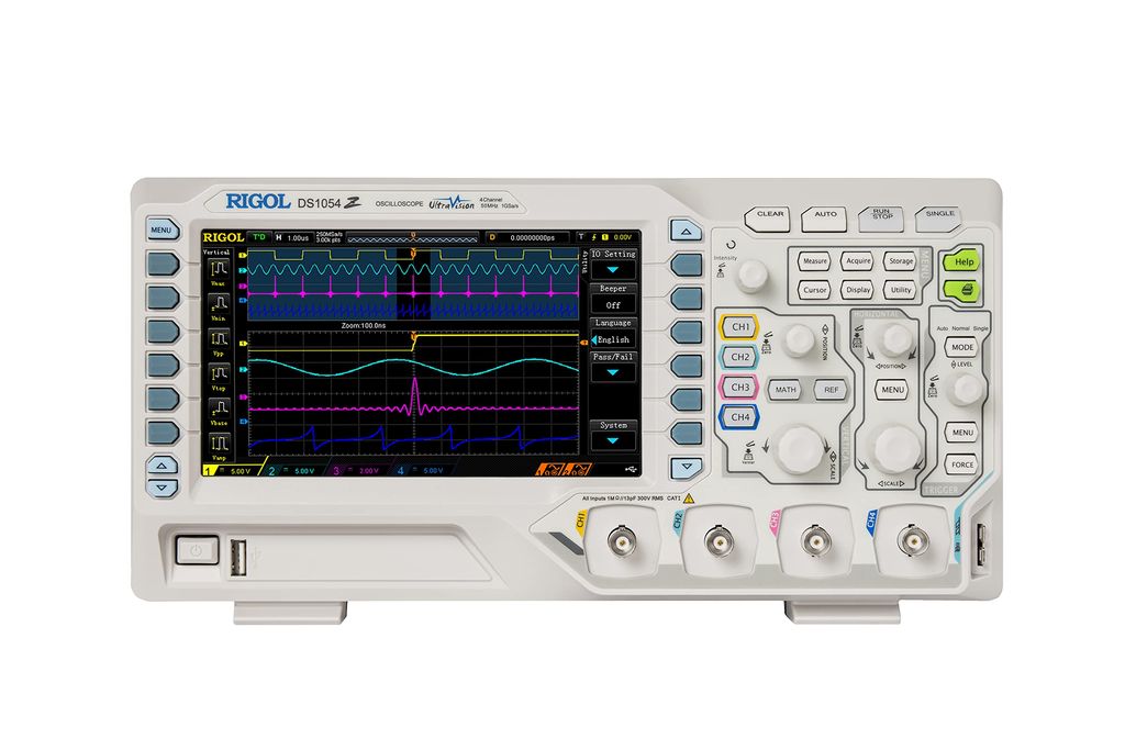
Specifications
| Memory | 24 Mpts (divided by number of channels) |
|---|---|
| Sample rate | 250 MS/s (4 channels active), 500 MS/s (2 channels active), 1 GS/s (1 channel active) |
| Display | 7" TFT, 800x480 pixels 160,000 colors |
| Input impedance | 1 MΩ |
| Number of channels | 4 |
| Horizontal scale (input) | 5 ns/div - 50s/div |
| Vertical Sensitivity (input) | 1 mV/div - 10 V/div |
| A/D converter | 8 bits resolution |
| Maximum voltage | CAT I 300 Vrms, CAT II 100 Vrms, transient overvoltage 100Vpk |
| Rise Time | DS1104Z: 3.5 ns DS1074Z: 5 ns DS1054Z: 7 ns |
| Probe support | 0.1x - 1000x |
| Measured noise value | 1 mVpp (at 100ms,1mV/div, record length: 3Mpts) |
| Connections | USB 2.0 type A, USB 2.0 type B, LAN |
| Weight (without box) | 3.2 Kg |
| Dimensions | 313 x 161 x 122 mm |
Coding the Quentorres
The Arduino Blink Code
                            const int ledPin = 26;
                            // the setup function runs once when you press reset or power the board
                            void setup() {
                              // initialize digital pin LED_BUILTIN as an output.
                              pinMode(ledPin, OUTPUT);
                            }

                            // the loop function runs over and over again forever
                            void loop() {
                              digitalWrite(ledPin, HIGH);  // turn the LED on (HIGH is the voltage level)
                              delay(1000);                      // wait for a second
                              digitalWrite(ledPin, LOW);   // turn the LED off by making the voltage LOW
                              delay(1000);                      // wait for a second
                            }
The Arduino Fade Code
                          int led = 26; // the PWM pin the LED is attached to
                          int brightness = 0;    // how bright the LED is
                          int fadeAmount = 5;    // how many points to fade the LED by

                          // the setup routine runs once when you press reset:
                          void setup() {
                            // declare pin to be an output:
                            pinMode(led, OUTPUT);
                          }

                          // the loop routine runs over and over again forever:
                          void loop() {
                            // set the brightness
                            analogWrite(led, brightness);

                            // change the brightness for next time through the loop:
                            brightness = brightness + fadeAmount;

                            // reverse the direction of the fading at the ends of the fade:
                            if (brightness <= 0 || brightness >= 255) {
                              fadeAmount = -fadeAmount;
                            }
                            // wait for 100 milliseconds to see the dimming effect
                            delay(100);
                          }
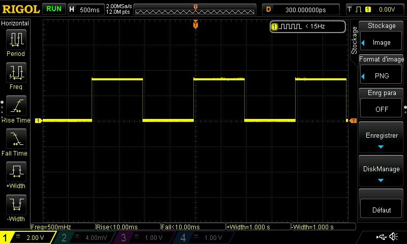
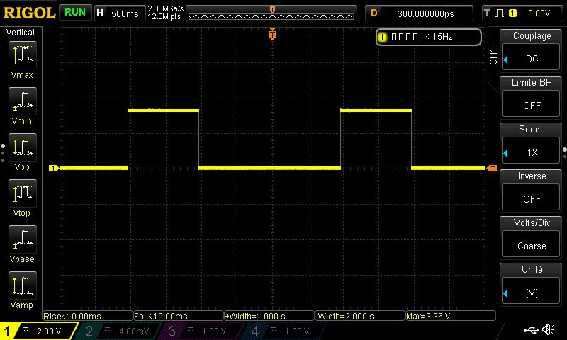
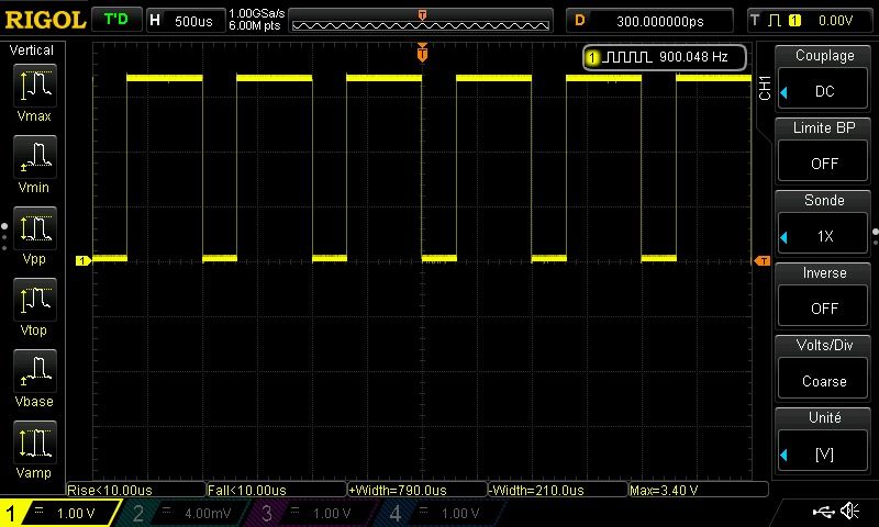
Microcontroller observation
The oscilloscope displayed different variations when we launched the blink program and then the fade program.
Link to our Group week 8 page
Individual assignment
UPDATE - Discovering Kicad
On our previous electronics assignments, we've already had the design files ready to be used (thanks to Quentin and Adrian).
This week it was our turn to do everything and for that we took our firsts steps in the "world of electonics board design" by learning to use the Kicad software.

Installation
After installing the Kicad program, you have to download and install the "Fab" Library (that already contain all the components we will use during the Fab Academy).
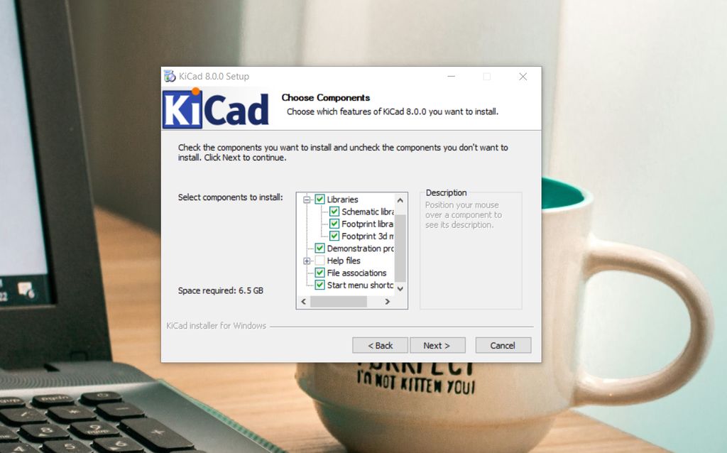
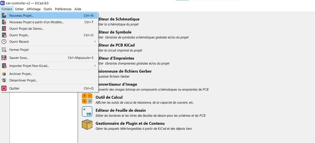
To install it in Kicad, store the library in C:/kicad/libraries (if you use Windows) then run Kicad and open a .pro file.
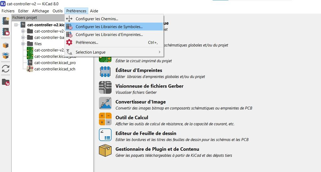
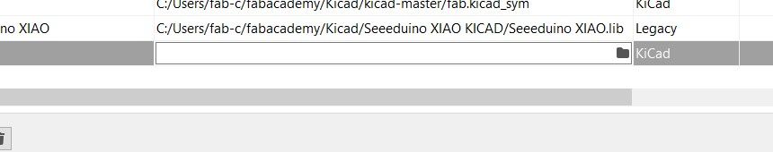
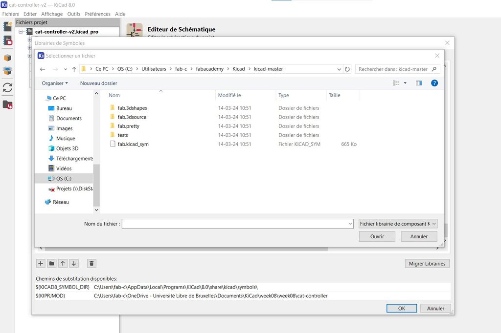
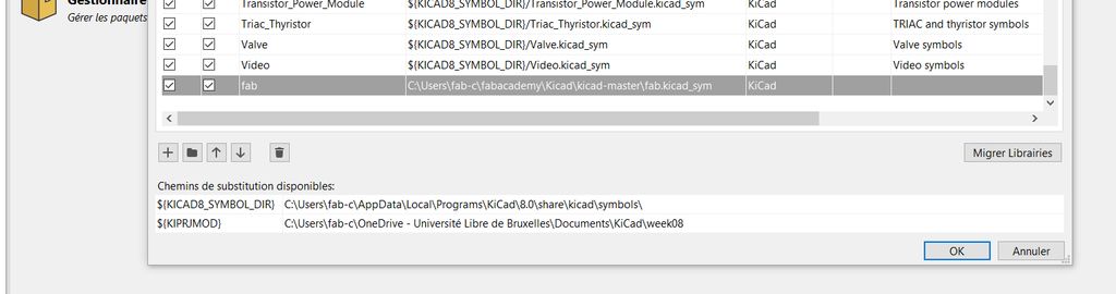
Click in the menu on "Preferences" then "Manage the symbol libraries" and add fab.kicad_sym as symbol library by clicking on the "+" sign (down-left of the chart).
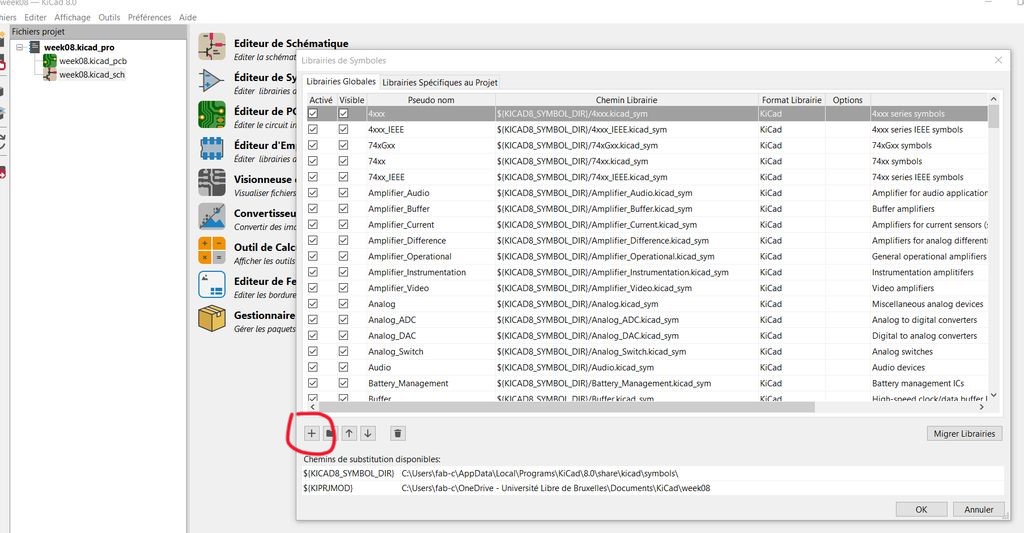
Fill the new empty row with "fab" as name and double-click on the folder sign of the "path" cell to open the "fab.Kicad_symb" file (that you added before in C:/kicad/libraries).
Close the window do the same for the footprint "fab.pretty" folder.
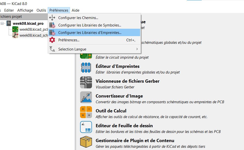
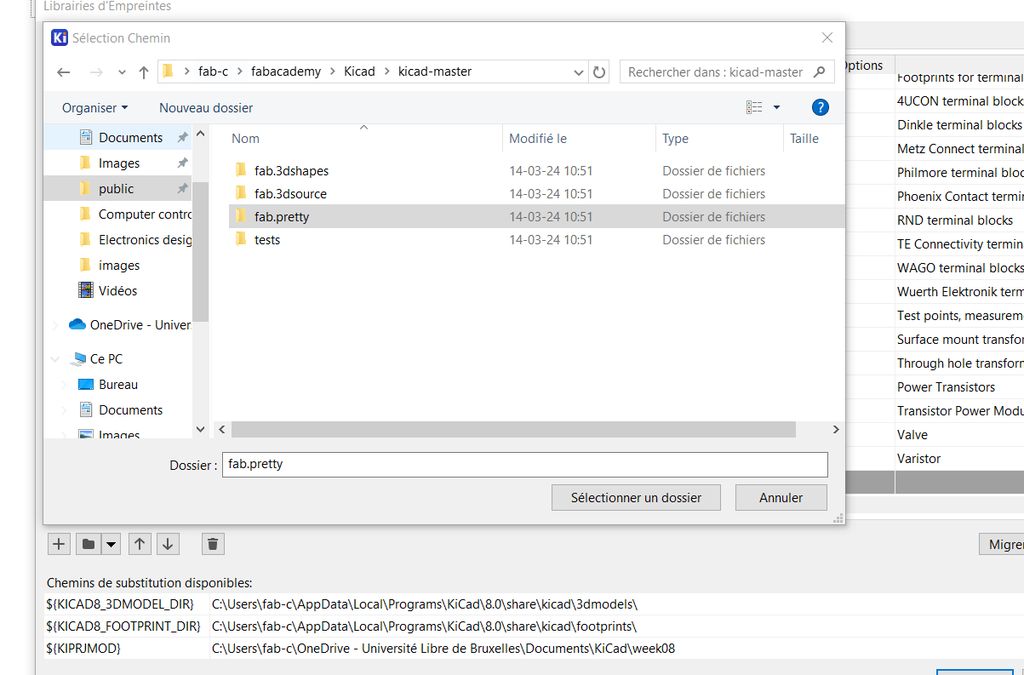
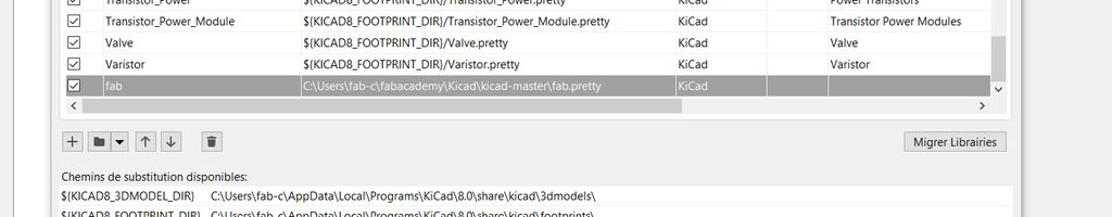
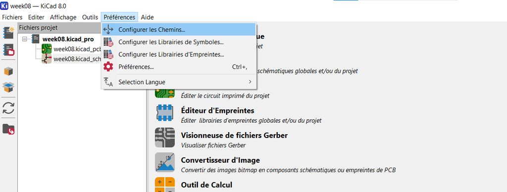
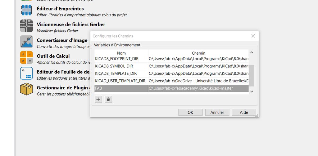
Last but not least, click again in the menu on "Preferences" and now open "Configure paths".
Add a new line and fill "FAB" as name and chose the "Kicad-Master" folder as path.
Project creation
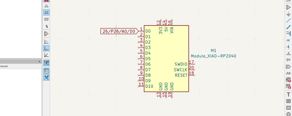
First you will work on the schematic. When you're on the schematic editor page you will have to add the components.
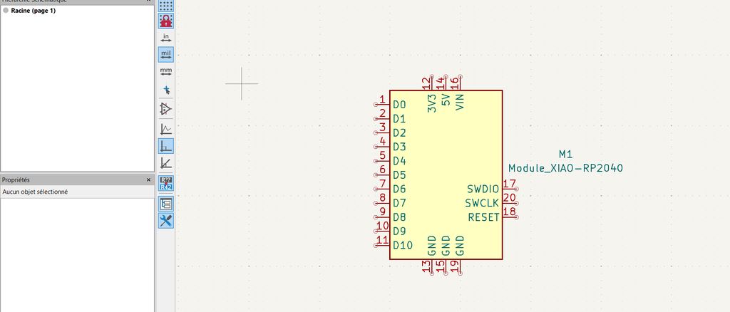
These can be found in the right bar under this symbol :
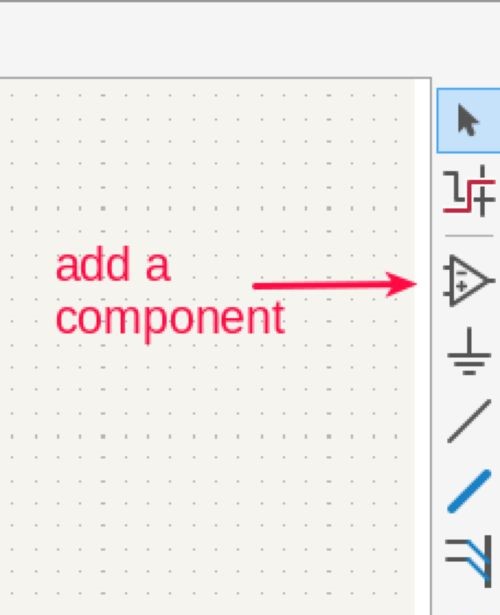
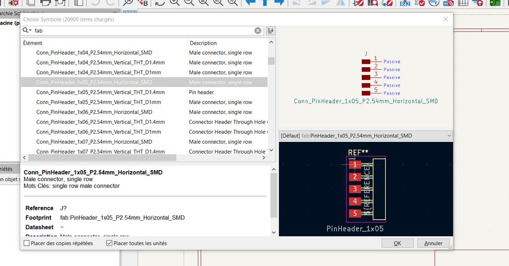
Thanks to the libraries we installed before, you will find all the common components that were/are used during the Fab Academy. Just go on "fab" and choose the one you need.
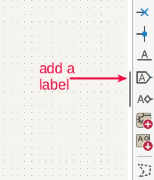
A good advice is to add labels to the pins of your components. Trust me, that will help in all the creation ! ;)
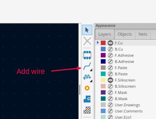
Next step will be to connect all your components together and then click on the icon to switch to the PCB editor.
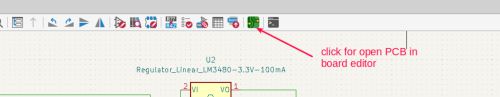
There you'll have to trace the routes, that will connect the components together after soldering, and draw the final shape of your PCB.
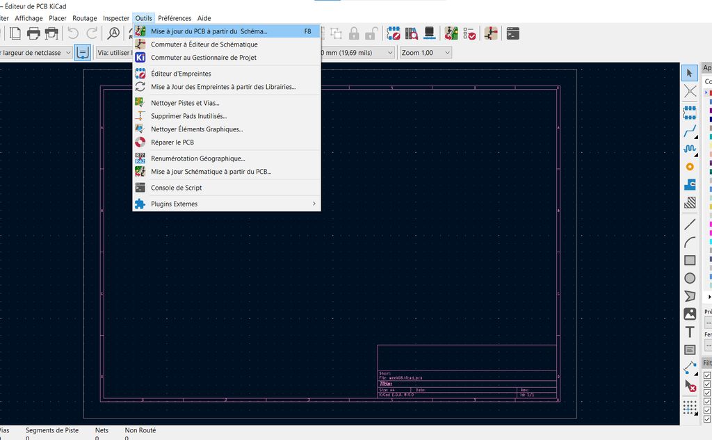
But first you'll have to update the PCB regarding your work in the schematic editor by clicking the button in the menu above.
Note : don't forget to click on this button every time you update your schematic ! ;)
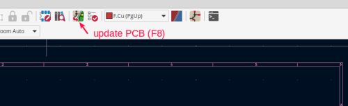
This button can also be found in the upper menu under "Tools"
For the routes you'll use this button :
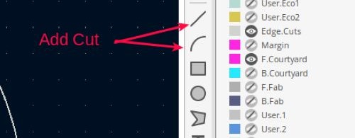
For the shape these ones :
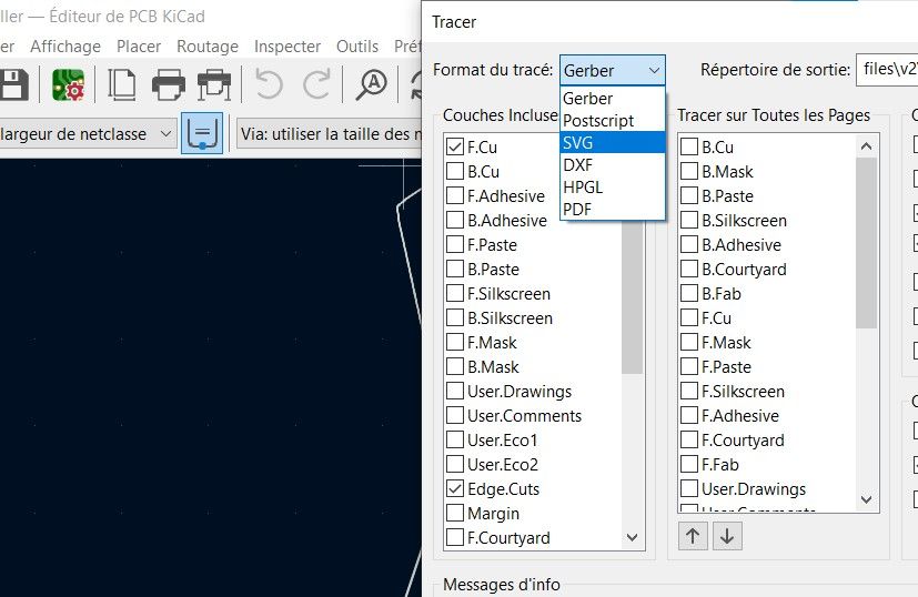
Once your PCB is finished you'll have to export it in SVG by clicking here :
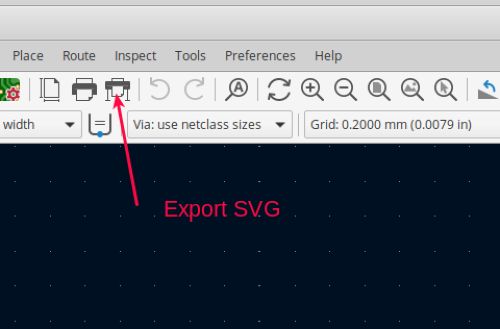
In the option window you'll have to chose SVG or GBR (regarding which program you'll use after to create the Gcode) as file format and check the F.Cu and Edge.Cuts boxes on the left.
Before exporting your file, make a DRC control. This will reveal some possible errors in your design.
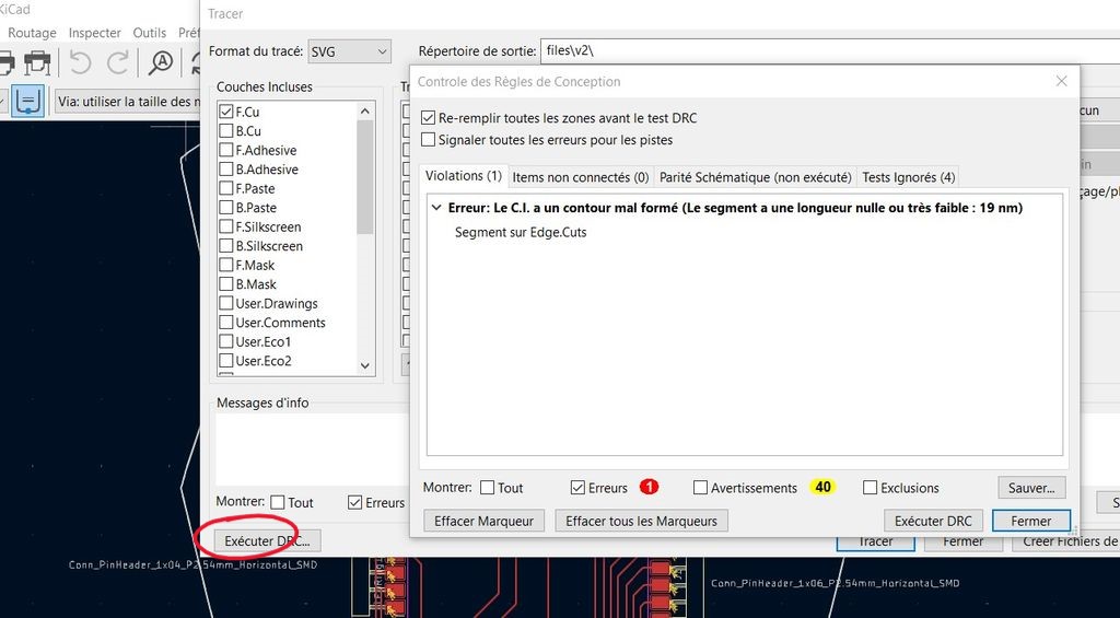
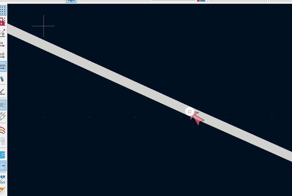
In my case, the error came from one of the edge cut. There were in fact 2 lines. So I deleted one and joint the other to the next one.
Regarding the warnings : they pointed to the text height of the labels but as I wasn't using them in the design I didn't have to take care of them.
To get the Gcode in mods you have 2 solutions :
- out of the .gbr files you can use the great gbr2img program made by Quentin Bolsee which will convert your files in PNG
- if you export your files in SVG you can open them afterwards in Inkscape and save them as PNG
My Micro-Cat-Controller
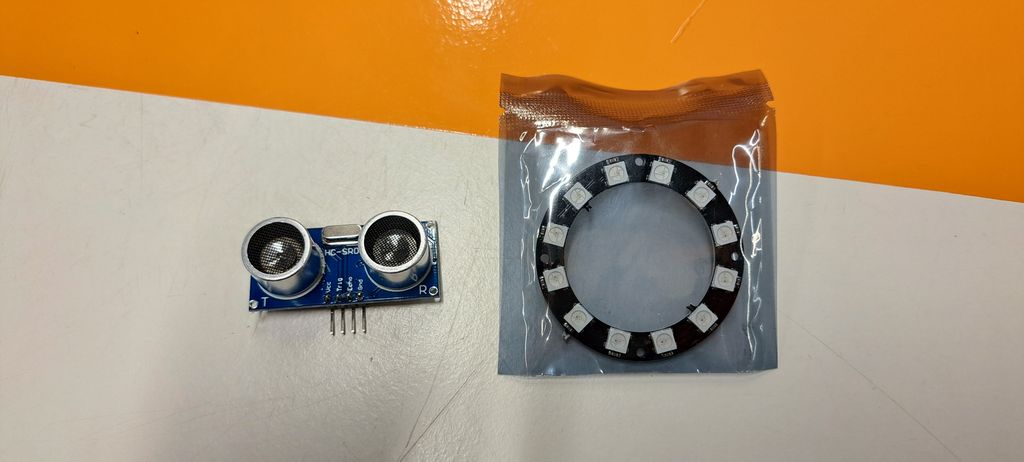
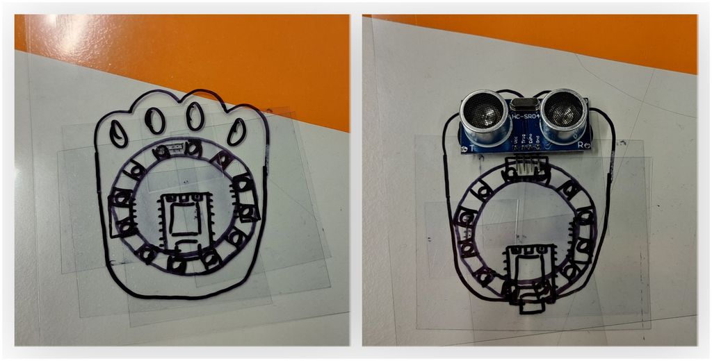
To create my electronics board, we chose some components that would be useful for my final project :
- A distance detector
- A LED ring
- A Seeed Studio
Design
Well, no surprise. I wanted to make a cat ! XD
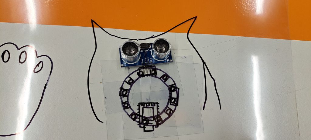
To find out the shape of the board and the components' placement, I first tried to draw everything on paper but then I came with the idea to draw the components on a transparent plastic A4 sheets, cut them out and place all the pieces manually like solving a puzzle.
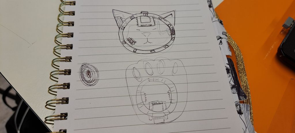
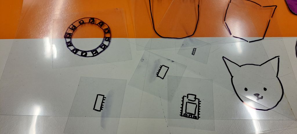
Then I took another transparent plastic sheet and covered the pieces to draw my "cat shape" ideas for the board.
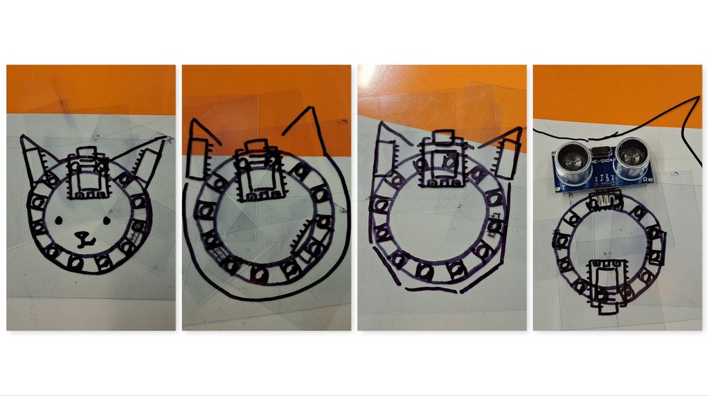
It really helped me to visualize how to place every piece of the complete board and how it would look like at the end.
It will result on a cat with an open luminar mouth requesting food !
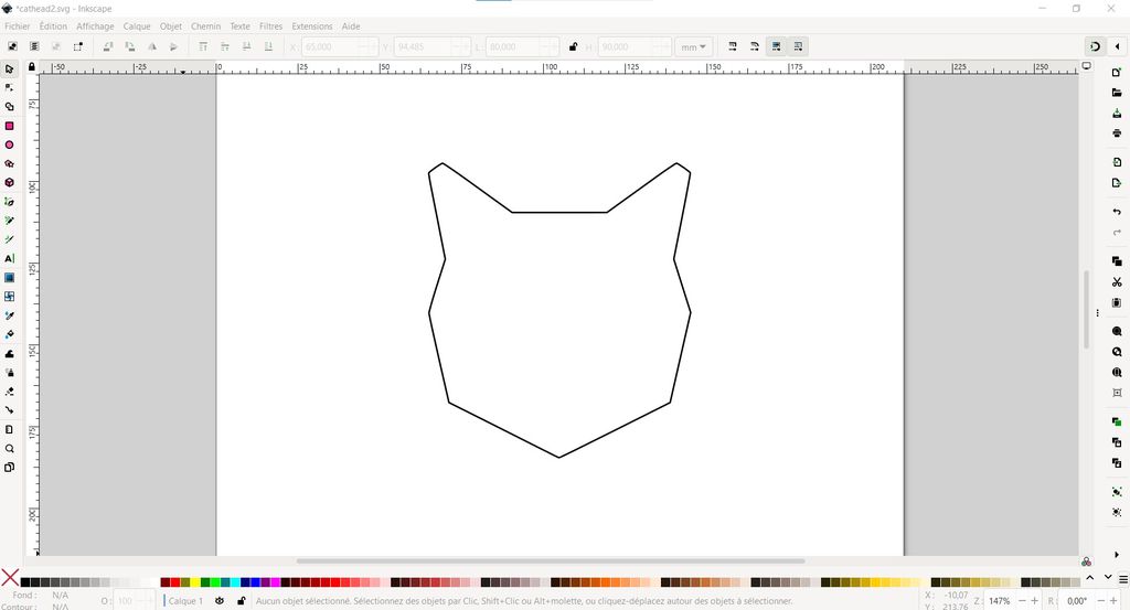
I first drew the cat head myself in Kicad but it didn't work out because the lines weren't closed all together so the GBR edges cut file was empty.
I searched after a solution on internet and found a video tutorial explaining how to import a complexe file made in Inkscape to use it as edge cut in Kicad.

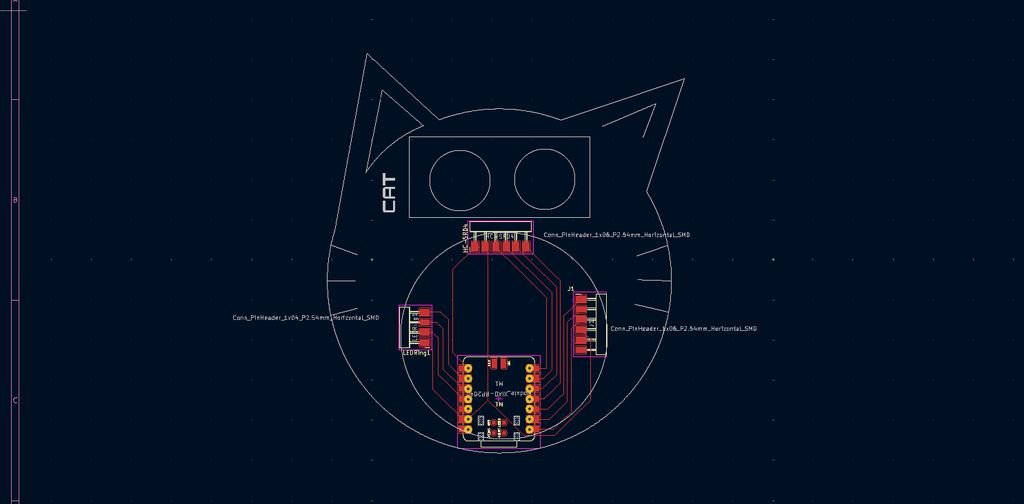
I chose on internet simple cat head silhouettes and vectorized one in Inkscape, following the instruction on the video tutorial.
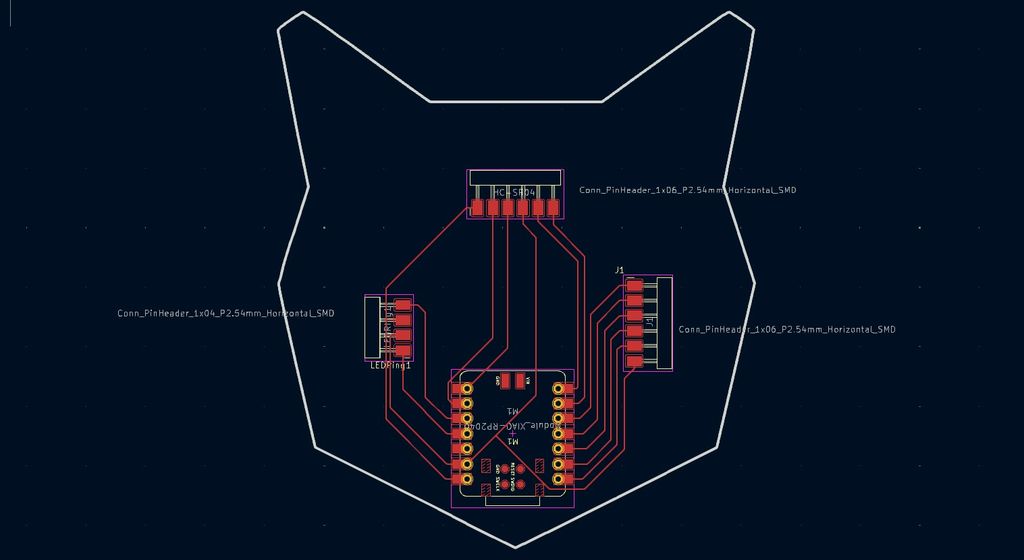
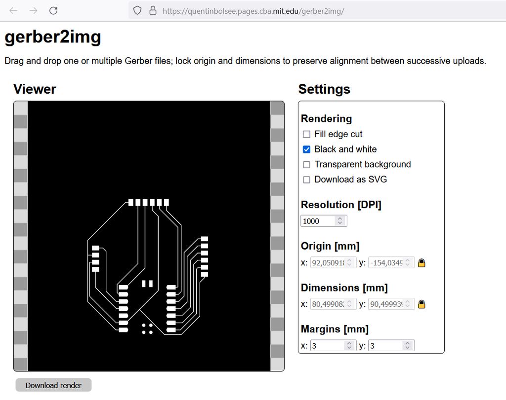
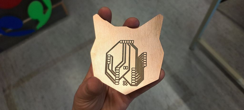
Funny thing is that I unintentionally placed the routes to look like a real cat face, with closed mouth and a nose (created by the Seeed Studio) !
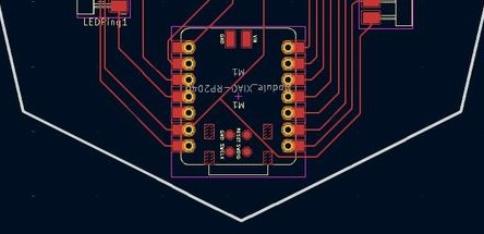
I generated the GBR files by clicking on "trace" in Kicad and then converted them in PNG images using the great gbr2img program made by Quentin Bolsee (thanks a lot ! <3).
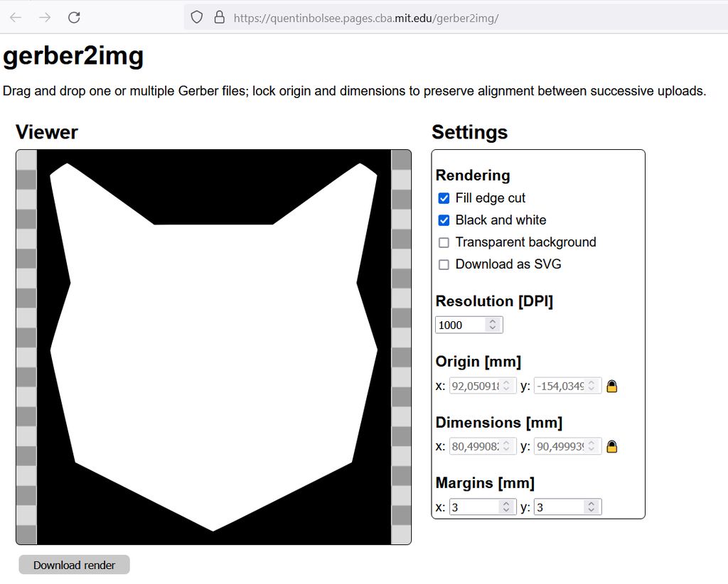
I had to change my cat head shape because the width was too large for the copper plate (100mm x 100mm)... So back in Inkscape I resized it to fit 80mm width, which was perfect without changing the whole board too much.
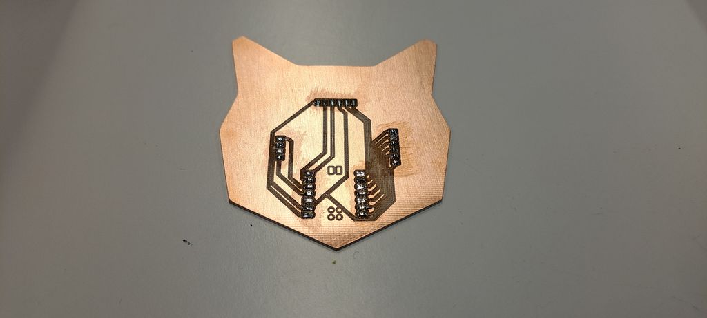
Milling
The milling part was simple.
After generating the G-Code of the interior file and the traces file in Mods with the right CNC parameters, I sent them on the CNC program.
After fixing the plate and the tool, we made the z-zero and launched the auto-leveling to mostly make sure that the shape really fits on the plate.
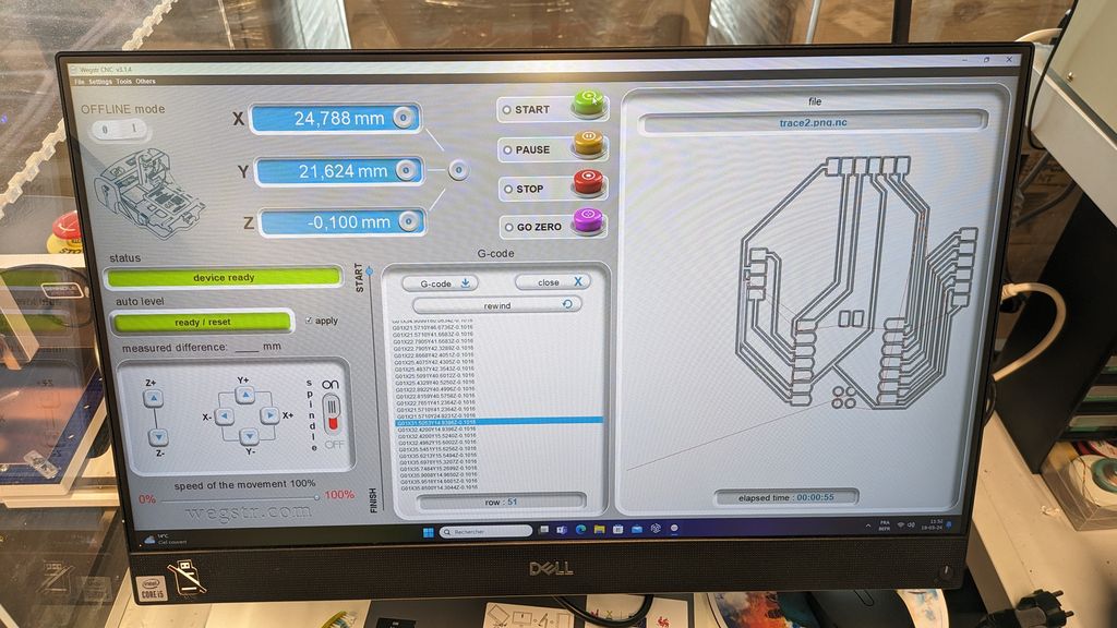
Time to launch the routes tracing. It took approximately 25min.
Next step was to quickly clean the plate with our mini duster, change the tool, check the z-zero again and launch the cutting.
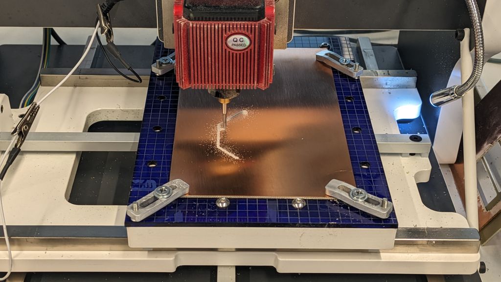
At the end, quick dusting, plate water cleaning (with soap and a toothbrush) + drying... and TADAAAA : a beautiful meow-cat-controller ! YAY :D <3
Soldering
First I prepared the newly cut PCB by adding flux and solder on the right parts.
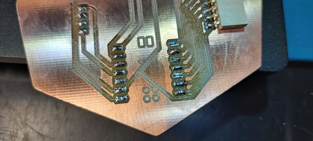
Next, I added the "horizontal" 6-pin connectors and then the Seeed Studio RP2040.
It was easier than my first soldering course but then I had to add another 6-pin connector (for the neopixel) but "vertically".
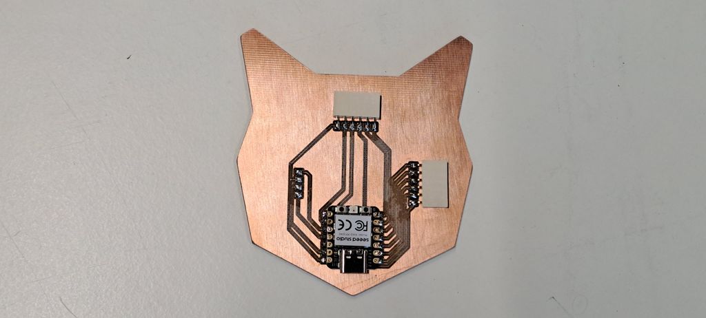
That was more difficult and I even failed so we used the "bending" technique to finally get it on!
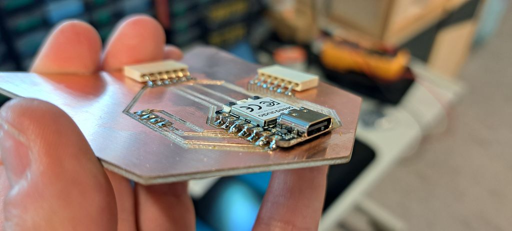
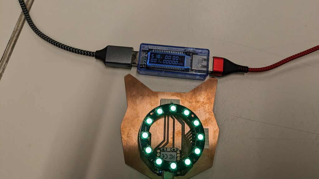
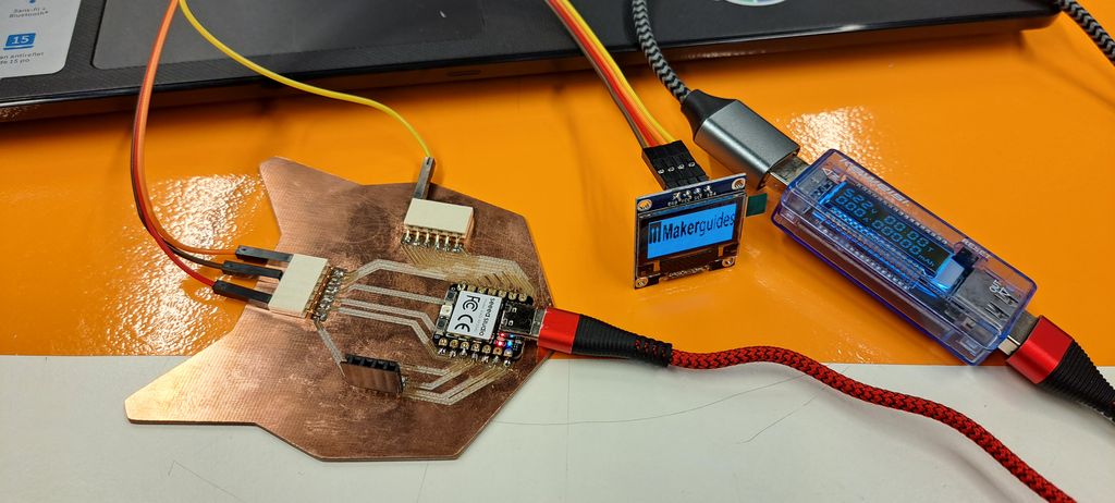
Functioning
Ultimate test : plugging in the cat-controller and...
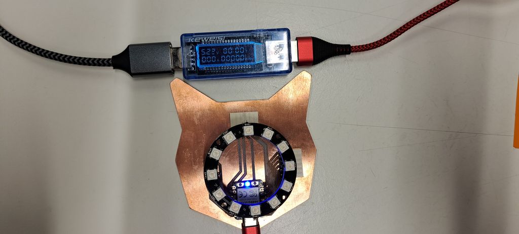
IT'S WORKING !
Here are more pictures from week09 with output devices :
Files and resources
My files
- Cat-Controller Kicad-Pro file
- Cat-Controller Kicad-PCB file
- Cat-Controller v2 Kicad-PCB file
- Cat-Controller Kicad-Schematic file
- Cat-Controller edge-cuts SVG file
- Cat-Controller v2 edge-cuts SVG file
- Cat-Controller edge-cuts DXF file
- Cat-Controller Interior PNG file
- Cat-Controller Interior G-Code file
- Cat-Controller Traces PNG file
- Cat-Controller Traces G-Code file
- Cat-Controller Interior v2 PNG file
- Cat-Controller Interior v2 G-Code file
- Cat-Controller Traces v2 PNG file
- Cat-Controller Traces v2 G-Code file
Resources