3. Computer Controlled Cutting
This week was all about cutting into different materials with the help of computer controlled cutting machines, in this case the laser cutter and the vinyl cutter.
My journey
I was excited to start this week's assignment as I already worked on these kind of machines and really love it.
Although it wasn't really something new to me, I took it seriously and I did well as I still learned new things and also had some fails, mostly by lack of attention.
For example : I forgot to put on the air extractor which resulted by some flames in the laser cutting machine.
Nothing serious but it could have been worse so
1st advice : ALWAYS CHECK EVERYTHING BEFORE STARTING (having a check list nearby can help) AND STAY BESIDE YOUR MACHINE TO WATCH !
I've also downloaded some files ready to be cut and they were in fact messy.
My 2nd advice : ALWAYS CHECK YOUR DOWLOADED FILES BEFORE USING THEM ON THE MACHINES !
Group project : Laser cutting
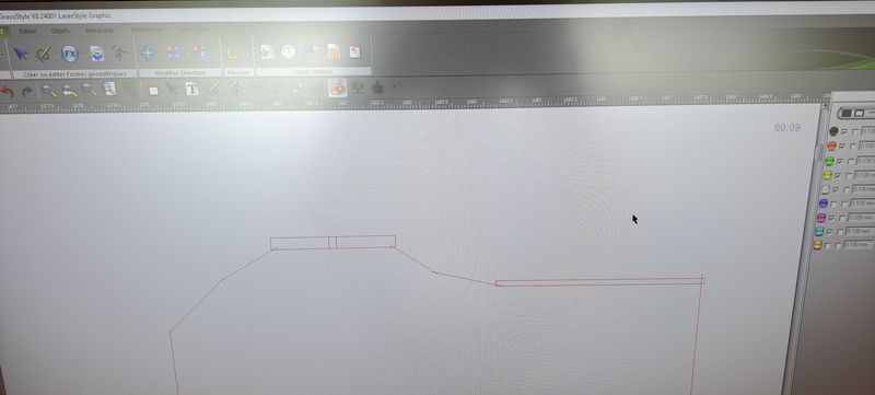
We designed some pieces in Inkscape and Fusion 3D (depending on our affinity with each of these softwares) to try out the laser cutter and understand the paramters that are important to keep in mind.
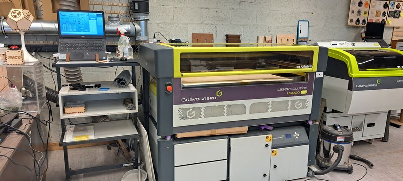
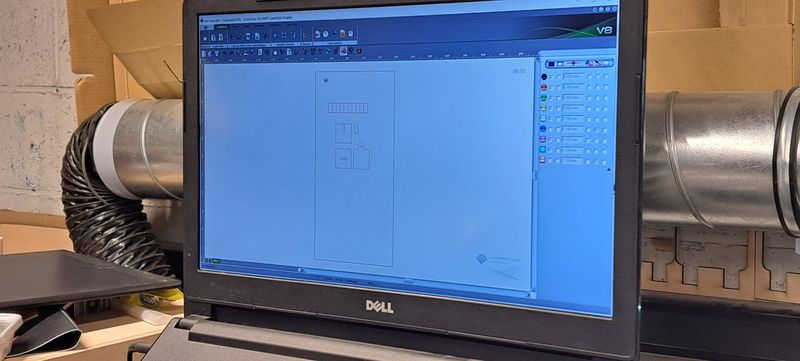
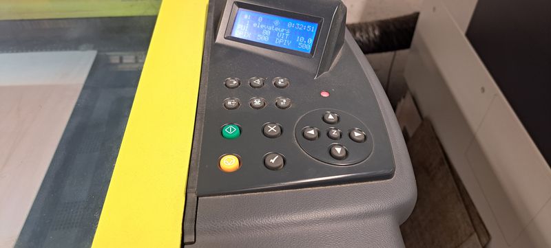
Our laser cutting machine is a Gravograph LS1000 XP.
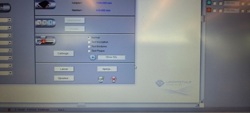
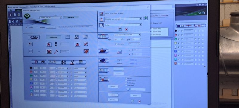
You can only their on program which is Gravostyle but it is pretty simple.
We imported our file in the program, adjusted the cutting parameters for our material.
In this case it was a wood board of 4mm so we put the speed at 10% and the power at 80%. We let the DPI at is default number, 500.
Focus
As the focus setting is really important because it'll determine the right cutting of the material, we've learned how to do it manually.
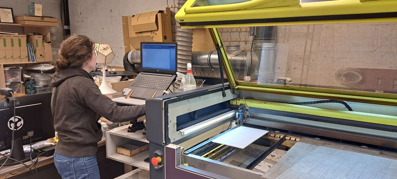
First step, we had to put the material on the laser cutter tray and make sure it is flat everywhere (to avoid a difference in the cutting or engraving at some places) and enter the right cutting parameters.
Then we put a piece on our material that has the right height for the perfect focus.
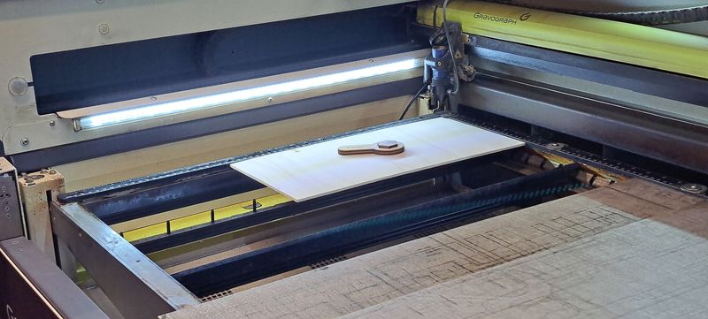
By using the arrow buttons on the right side of the machine, we moved the laser so that it ends right above the "DIY focus measure piece".
We lowered the laser cutter tray and moved it back up until the "DIY focus measure piece" touches lightly the palper of the machine.
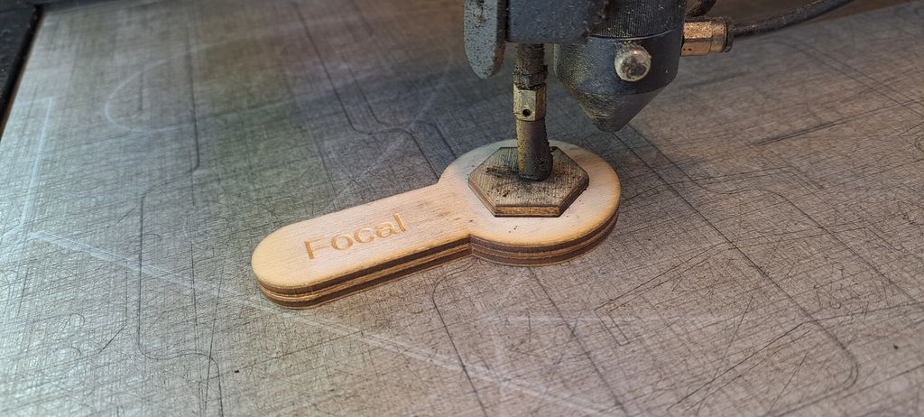
Last step, push the "check" ("V") button, close the machine and press the green start button
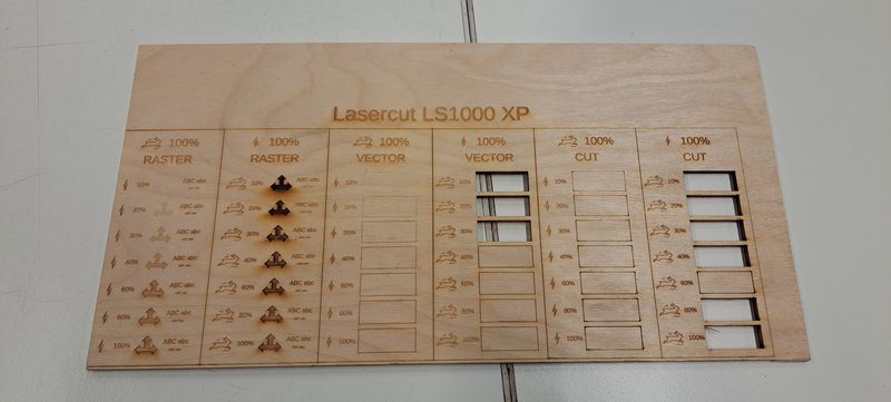
Power and Speed
To determine the power and speed of the laser, there is a test jig that allows you to view different parameters.
But you have to be careful, these parameters are valid only as an indication, it will be necessary to test it before, especially if the material is not the same.
Kerf
The kerf is also called "cutting width" or "laser line thickness". It is a key parameter to consider when creating files for laser cutting (or any machine that cuts digitally or not) :
- To make perfect interlocking joints which is important for the fit.
For example, for a notched box, you can create a model that assembles by force and does not require nails or screws.
For other volumes, this allows sufficient support while the glue sets. - To better anticipate the final result.
- To determine how much material you can leave when cutting.
When you want to remove a lot of material to leave very fine lines, knowing this information is essential.
Generally, it is said that it is better to leave as much width as thickness of material.
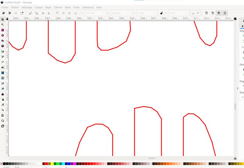
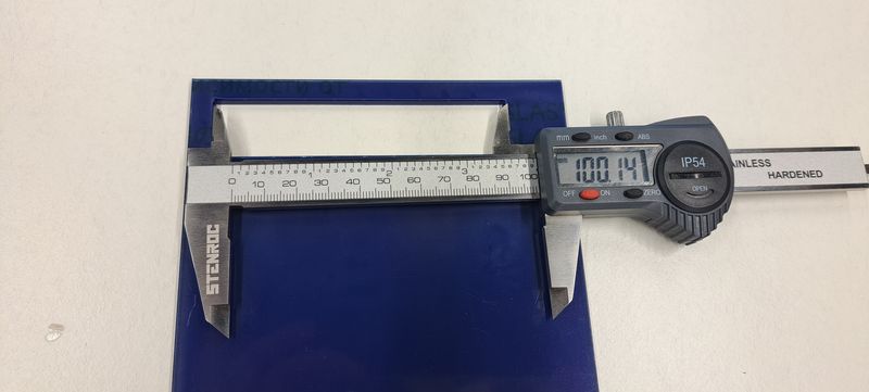
To get the right kerf measure for our laser cutter machine, we designed 10 rectangles of 10mm length each that we put side by side to get a 100mm length big rectangle.
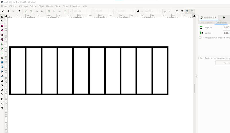
We took care to not design each rectangle completely (we only traced the top, bottom and right sides, and closed the drawing by adding the left side only at the last piece) to avoid a double passage of the laser and by then compromise the result.
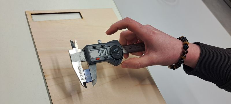
After cutting the pieces in a 4mm wood plate, we measured the length of the big rectangle hole in the plate, then the length of one of the little pieces and a the end the length of all the little pieces together to really realize the difference because of the kerf.
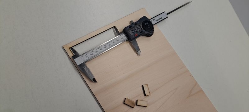
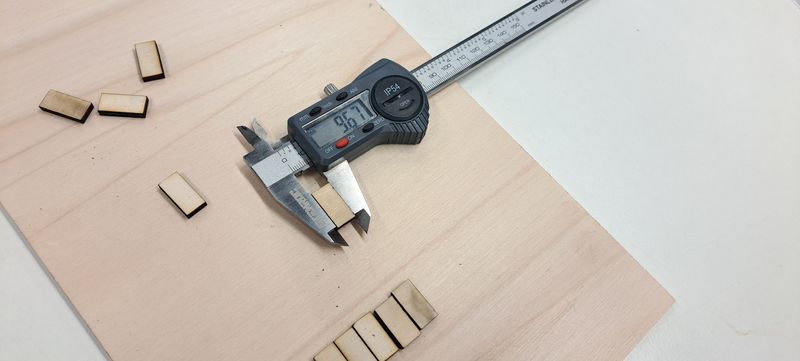
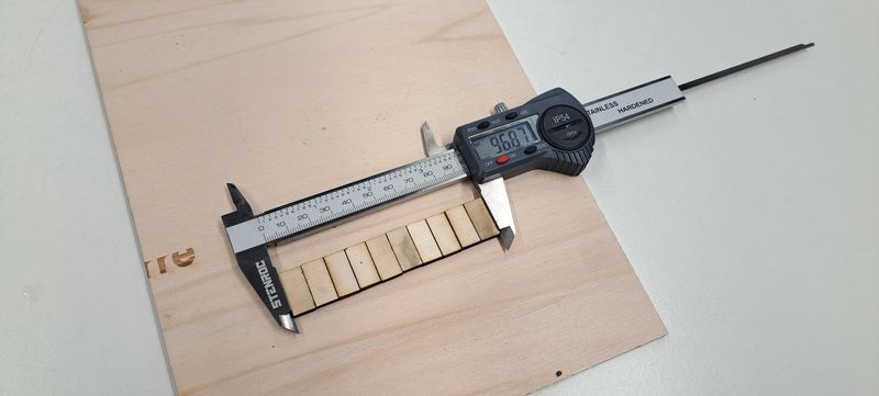
After a small calculation to determine this kerf we got as result : 100 mm - 96.87 mm = 3.13 mm 3.13 mm / 10 = 0.313 mm
kerf = 0.31 mm so ~0.3 mm
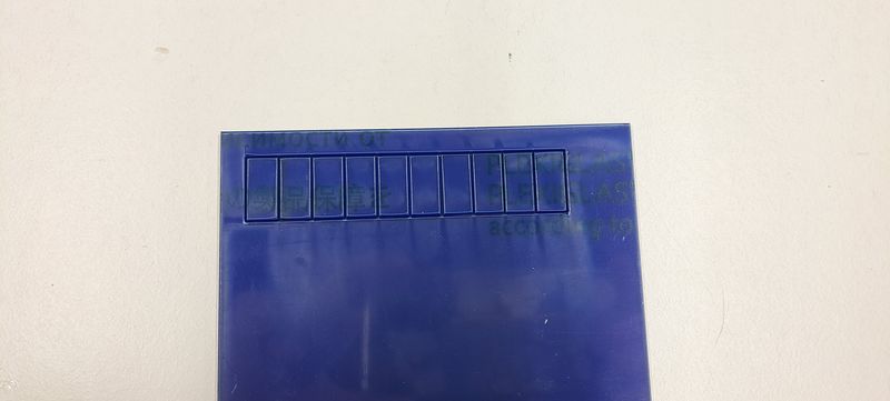
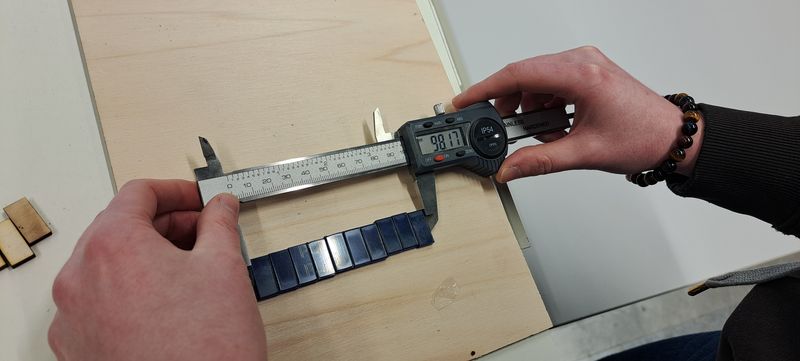
We did the same process with a 3mm plexiglas plate and it gave us this result : 100 mm - 98.17 mm = 1.83 mm 1.83 mm / 10 = 0.183 mm
kerf = 0.18 mm so ~0.2 mm
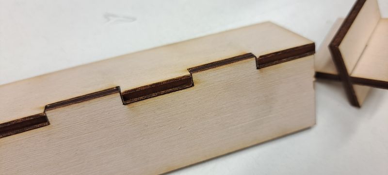
Joint types
We've selected 4 different types of joints and shared the work of creating the designs.
We joined then to prepare the laser cutter machine and cut the pieces.
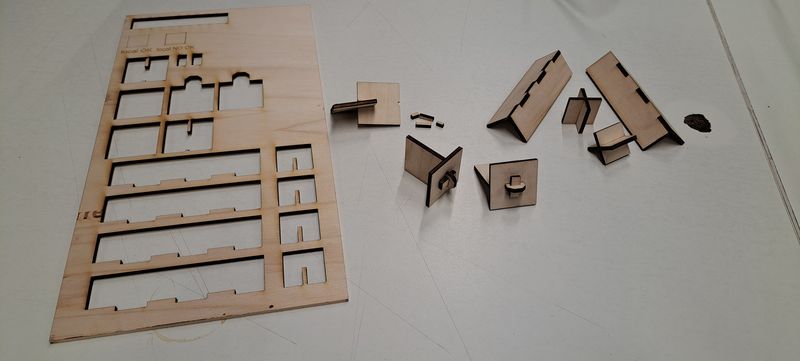
For the easiest pieces, we had no problem. The sizes were right.
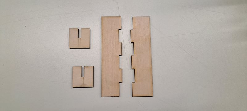
The 2 others were trickier.
We made 2 size tests for the wedge joints and had difficulties to put the pieces together with one of them. It was too tight.
And for the snap-fit joint, it was a fail. This one really isn't so easy to design. We will try it again.
Link to our Group week 3 page
Individual project : parametric construction kit
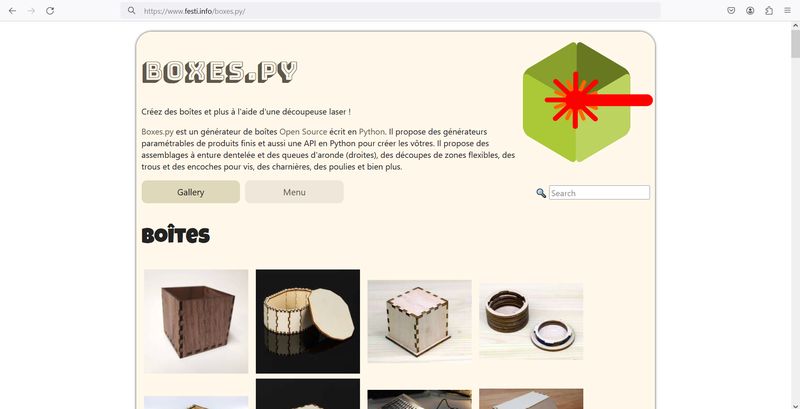
Despite the fact that I previously learned how to calculate the kerf and how to design a 3D object, I chose to use 2 websites to help me create the boxes I wanted to cut on the laser cutter for this assignment.
The reason is simple : saving time and brain energy as this kind of calculation isn't easy for me.
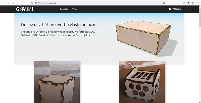
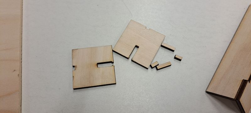
I chose to work on a basic box as it will be the base form for my final project. By already cutting it in a smaller size in this assignment, I can have a first idea of the possibilities of construction.

Even if I entered the right parameters, the pieces didn't stick together so I'll have to try it again.
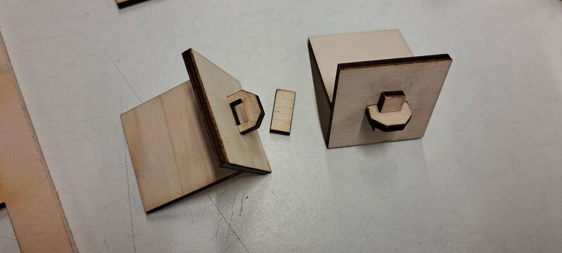
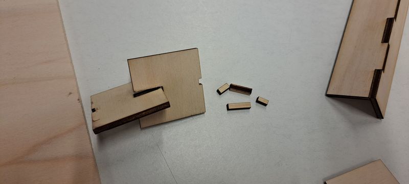
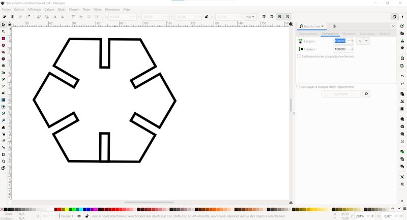
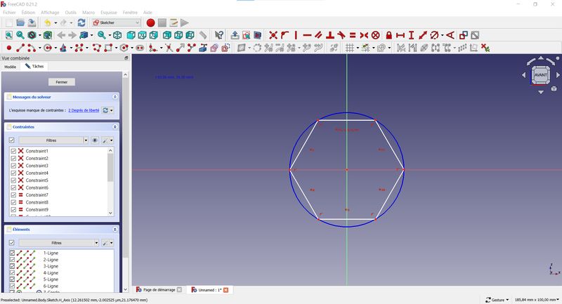
I've also designed a simple little hexagone piece with notches in Inkscape.
I started by cutting 2 of them to verify that they would fit together, which they did (woohoo !).
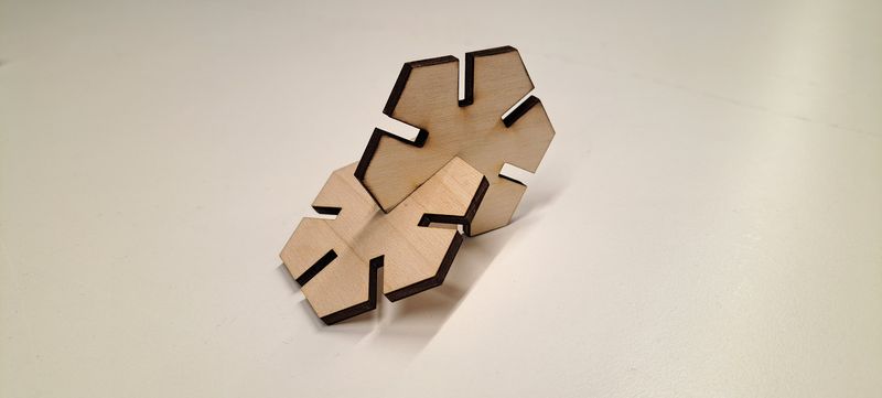
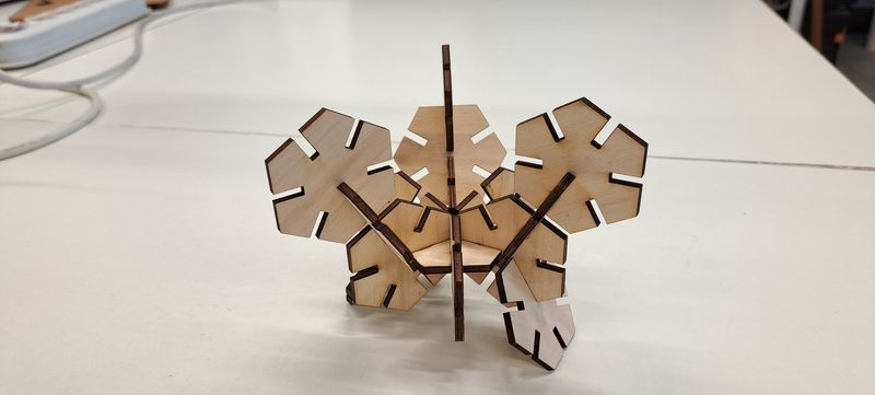
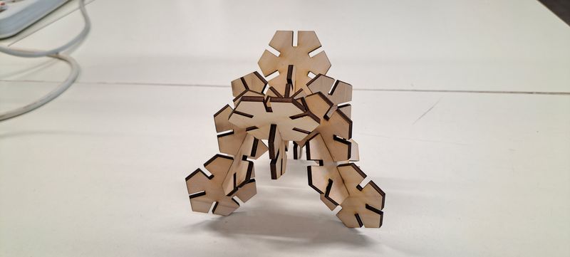
I cut a dozen more to be able to create new bigger 3D pieces.
It was mentioned to me that Inkscape isn't a parametric program and that I forgot the main task of this week's assignment which is "creating a parametric design" so I jumped into Freecad to design this piece again and work with the spreadsheet.
For that, I sketched the hexagone, extruded it with the tools of "Part Design"'s workshop' and clicked on the "spreadsheet" workshop.
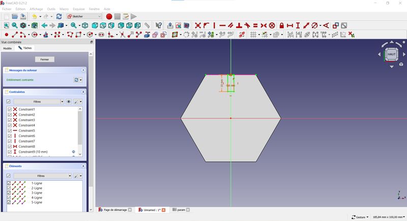
In the table, I named each piece of my object, gave them their "alias" and added the measures.
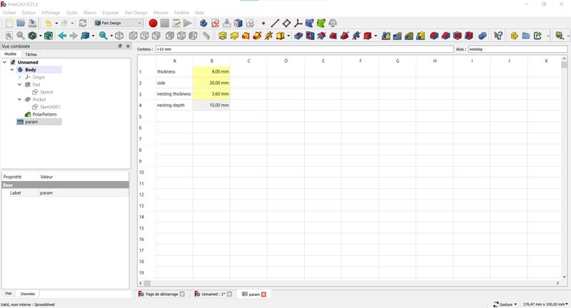
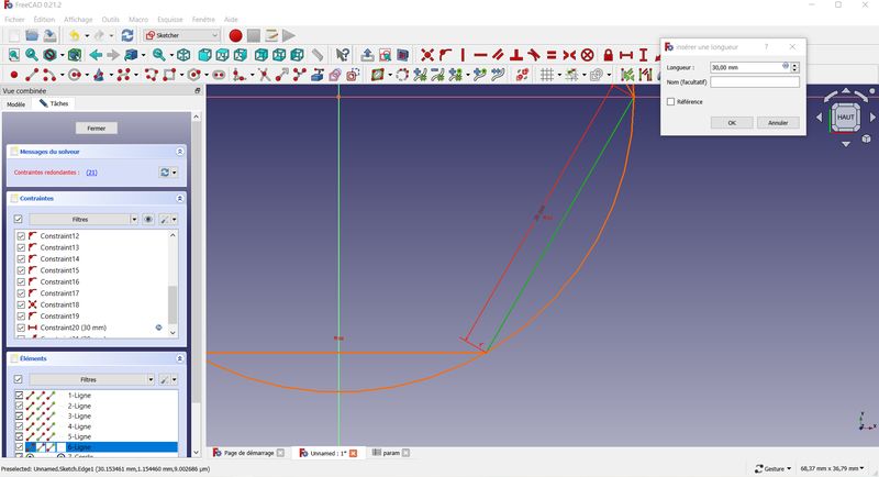
I went back in the sketch, clicked on the side of the object I want to link to the table and entered the path with the "Dimension constraint tool".
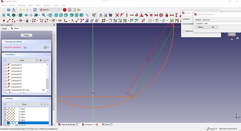
Of course I couldn't finish the assignement without making at least one ... tadaaaaa :
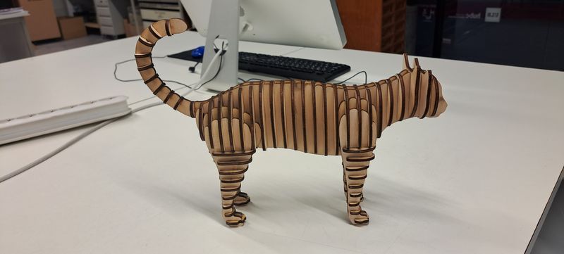
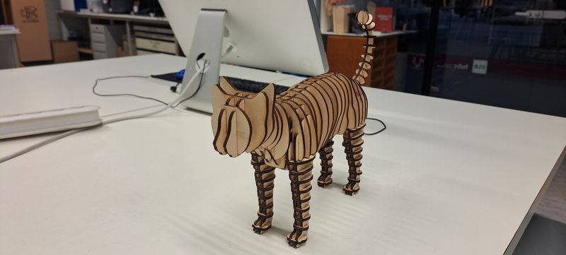
Yes, A CAT ! :D
Individual project : vinyl cutting
The vinyl cutter machine we have in the FabLab de Charleroi is a ".." and is interesting as his blade is a ... one. This machine is really easy to use !
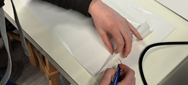
First, I vectorised the Fab Academy logo and measured the place on the notebook. Then I made sure to adjust the vectorised file in Inkscape to fit in.
After saving the file in .pdf format, I opened it in the vinyl cutter program, "Summa GoSign".
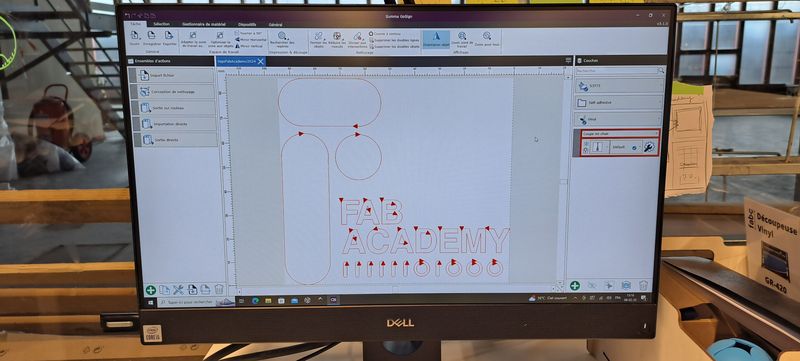
All I had to do then is :
- select vinyl as material
- select "half-material" cut
- roll
- outside boxing
- completely cut the vinyl paper at the end
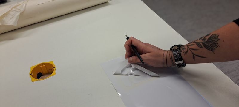
Once the machine is done, I had to remove the excess around my design, which is called weeding.
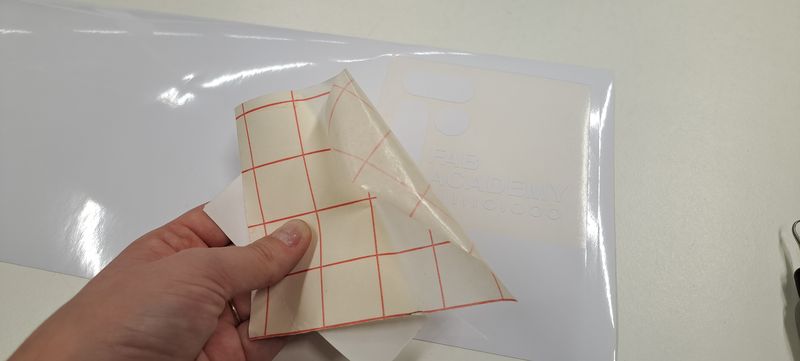
Then I put a transfer paper on it to remove the design from the protection sheet without displacing the different pieces.
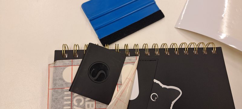
And finally I placed and sticked it on my notebook, taking care of removing the air bubbles with the squeegee and avoid wrinkles.
My Project
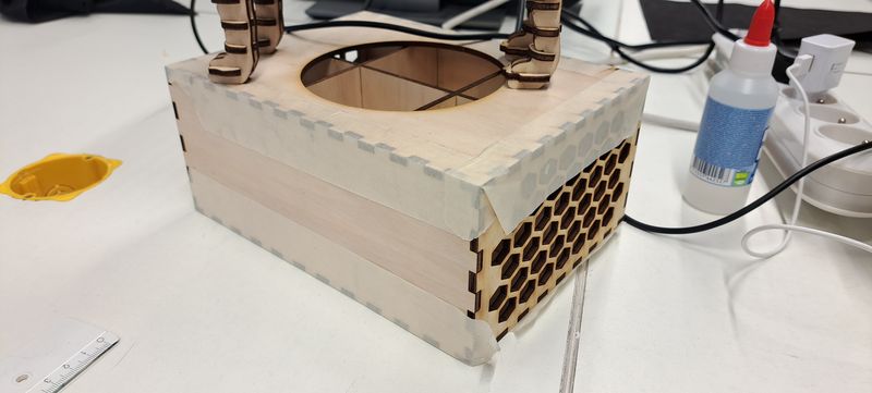
As I said earlier, I took advantage of this week's assignment to cut the basic parts of my "pet house" project.
This helped me see and think about the parameters I have to take in consideration and what difficulties I can meet.
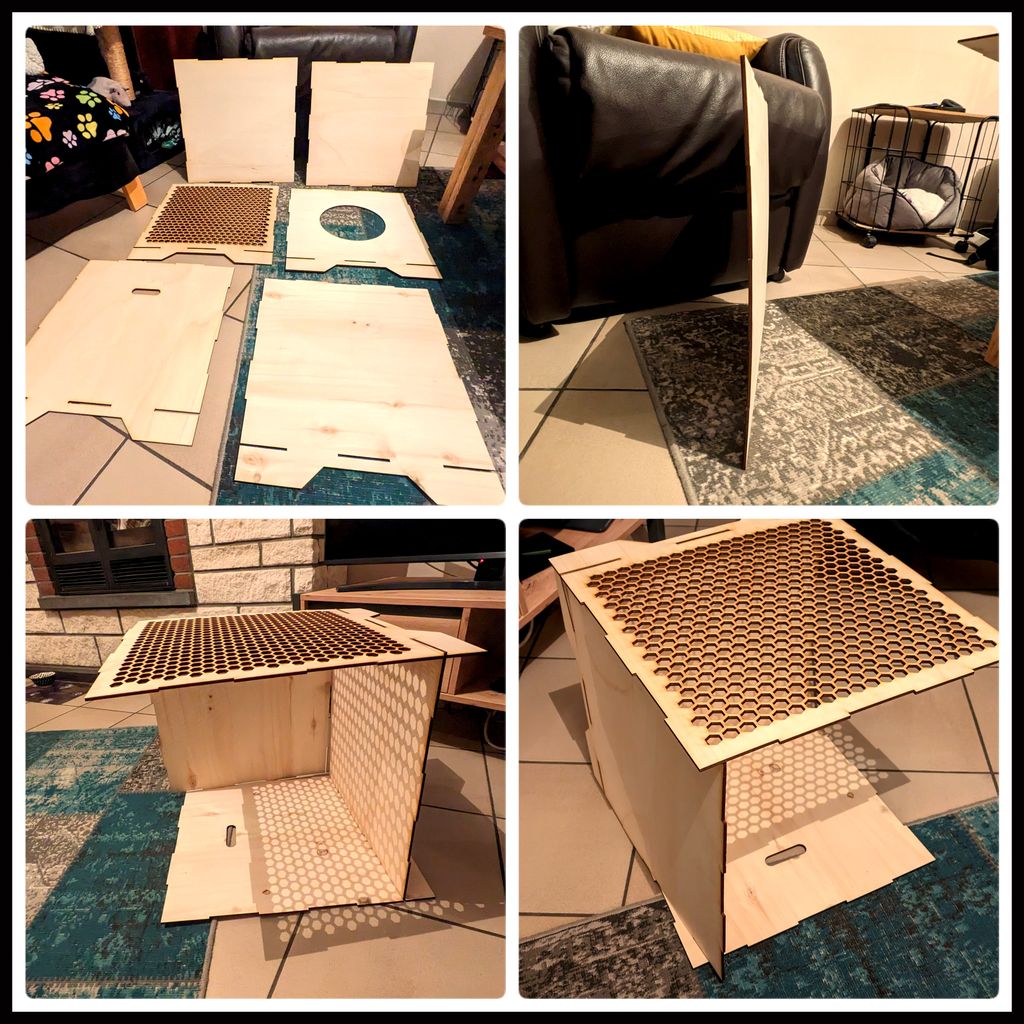
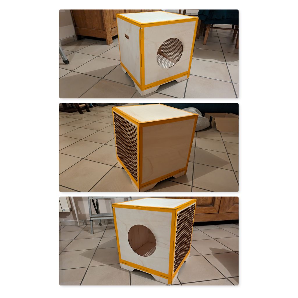
The kerf wasn't quite right on it so the box is falling appart. Good example on how it is important to get the right measures and what difficulties it can bring if you fail at it !
Files and resources
My files
- Power and Speed Test file
- Joint and kerf file
- Simple Box file PDF | SVG
- Box with insert file - Box PDF | SVG
- Box with insert file - Insert PDF | SVG
- Cat file
- Parametric Construction Hexagone file
Resources