13. Networking and Communication
Hero shot
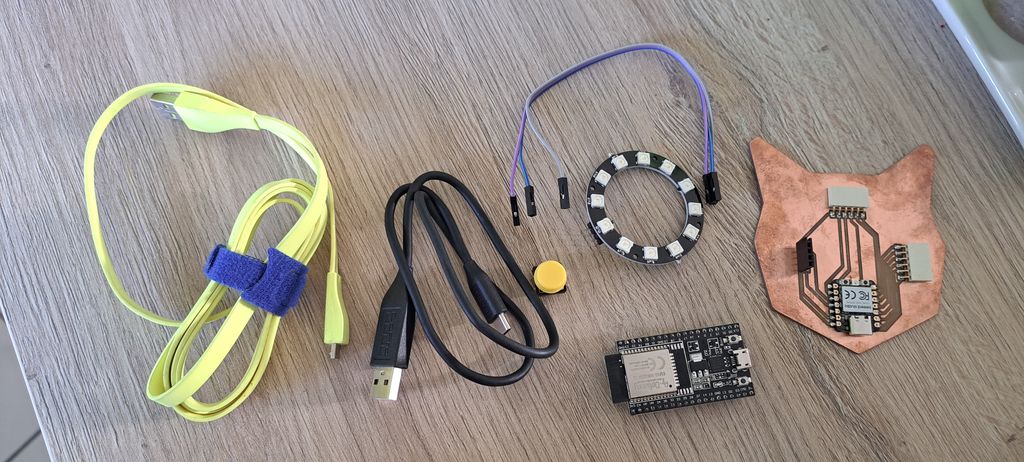
Materials used during the assignment
- ESP32 WROOM
- Button
- My "cat-controller"
- Neo pixel LED ring
- Cables
...And my cat... To supervise my work !
Installing the ESP32 Board
To use the ESP32 in Arduino IDE, you'll have to install it :
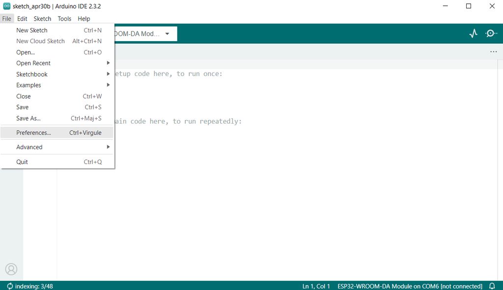
- In Arduino IDE, open the "File" menu and click on "Preferences"
- Go down to the “Additional Board Manager URLs” field and copy/paste the line below in it
https://raw.githubusercontent.com/espressif/arduino-esp32/gh-pages/package_esp32_index.json
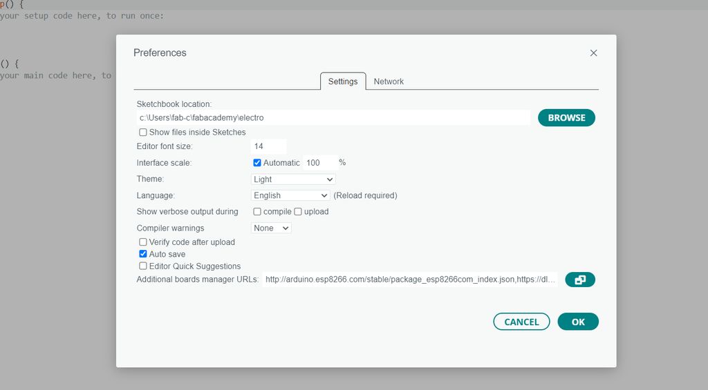
- Press "ok" to close the window
- Open the Boards Manager by going in the "Tools" menu, then on "Board" and finally "Boards Manager…"
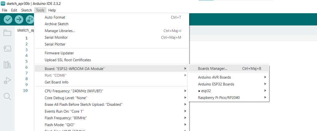
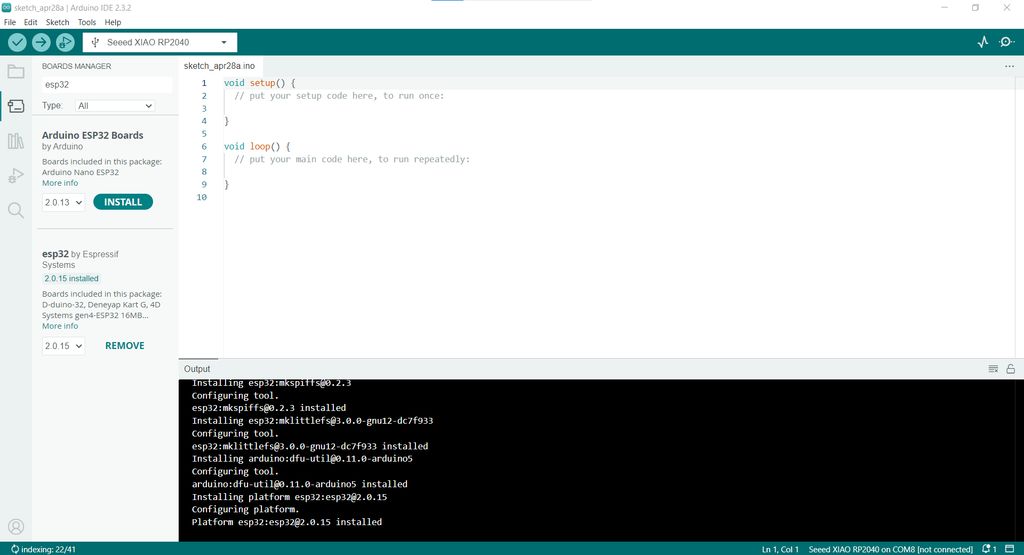
- Search for ESP32 in the search field and install the “ESP32 by Espressif Systems“ board
Testing the ESP32 - Without wifi
First let's check if the ESP32 is correctly working by following this ESP32 + button tutorial found on ESP32 I/O's website.
For that, connect a button on a GND (or VCC) pin and a digital pin of the ESP32.

Plug the ESP32 in your computer, open Arduino IDE and copy/paste this code :
                          #define BUTTON_PIN 21 // GIOP21 pin connected to button

                          void setup() {

                            Serial.begin(9600); // initialize serial communication at 9600 bits per second

                            // initialize the pushbutton pin as an pull-up input
                            // the pull-up input pin will be HIGH when the switch is open and LOW when the switch is closed.
                            pinMode(BUTTON_PIN, INPUT_PULLUP);
                          }

                          void loop() {

                            int buttonState = digitalRead(BUTTON_PIN); // read the state of the switch/button


                            Serial.println(buttonState); // print out the button's state
                          }
Upload the code on the ESP32 and open the serial monitor.
Eerytime you press the button, you'll see the number "1" change in "0".
"1" = High and "0" = Low
Personal issues
- ESP32 not working :
First, I had to change the ESP32 (fortunately I ha d2 of them). I doesn't seem to stay on...
UPDATE : it does work ! I tried it again after making the changes below and here is the result :
- COM port not connected ? :
As I tried to upload the code on the ESP32, it didn't work at first.
The COM Port "wasn't connected".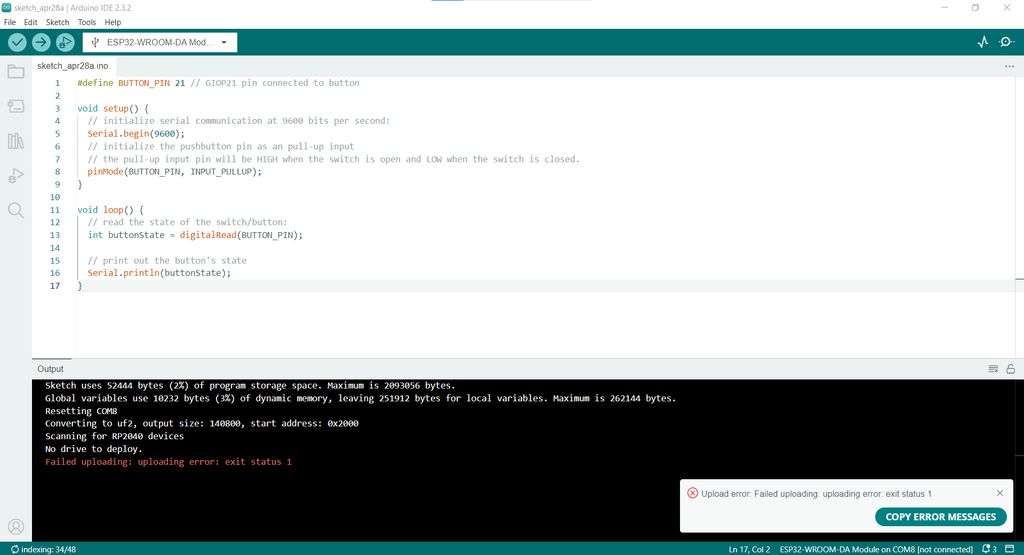
I tried to select another one in the "Tools" menu but I couldn't. The option was blocked.
After several different attempts in Arduino IDE (like selecting all the different ESP32 boards or clicking on "debug". Why not?!), I did some research on internet and found the website Random Nerd Tutorials.
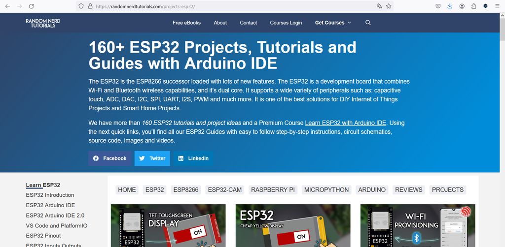
There is the "ESP32 Troubleshooting Guide" which sent me to install missing CP210X drivers that can be downloaded on the Silabs' website.
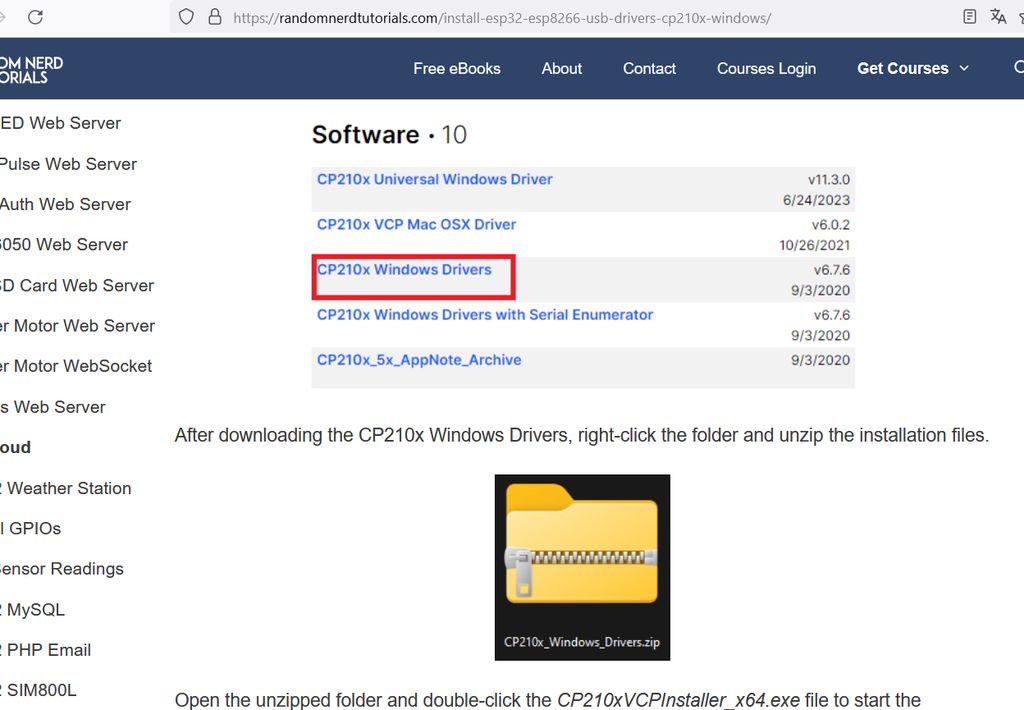
Once done, the ESP32 COM port appeard in Arduino IDE as I plugged it in the computer !
Testing the ESP32 - With wifi
The next step is to check that the ESP32 is connecting to the wifi.
Installing Mosquitto
To test the ESP32 with WiFi we need a broker to use the MQTT protocol.
Eclipse Mosquitto is an open source (EPL/EDL licensed) message broker that implements the MQTT protocol versions 5.0, 3.1.1 and 3.1.
Mosquitto is lightweight and is suitable for use on all devices from low power single board computers to full servers.
The MQTT protocol provides a lightweight method of carrying out messaging using a publish/subscribe model.
This makes it suitable for Internet of Things messaging such as with low power sensors or mobile devices such as phones, embedded computers or microcontrollers.
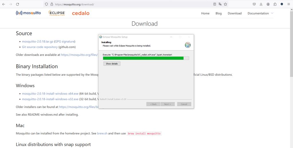
ESP32 working with wifi
To try the ESP32 wifi connection here are 2 different codes.
- ESP32 wifi test 1
                              #include < WiFi.h >
                              #include < PubSubClient.h >

                              #define PIN_BUTTON 21
                              int state_btn = HIGH;

                              const char* wifi_ssid = "xxxx";
                              const char* wifi_password = "xxxx";

                              void setup() {
                                pinMode(PIN_BUTTON,INPUT_PULLUP);
                                Serial.begin(9600); //starts serial monitor
                                WiFi.mode(WIFI_STA);
                                WiFi.begin(wifi_ssid, wifi_password);
                                Serial.print("Connecting to WiFi.."); //writes the text on serial monitor
                                while (WiFi.status() != WL_CONNECTED) {
                                  Serial.print('.');
                                  delay(1000);
                                }
                                Serial.println("");
                                Serial.println(WiFi.localIP());
                              }

                              void loop() {
                                // put your main code here, to run repeatedly:
                              int state_new = digitalRead(PIN_BUTTON);
                              if (state_btn && !state_new) {
                              Serial.println("pressed");
                              }
                              state_btn = state_new;
                              delay(1);
                              }
                              #include < WiFi.h >
                              #include < PubSubClient.h >
                              #define PIN_BUTTON XX
                              int state_btn = HIGH;

                              const char* wifi_ssid = "XXX";
                              const char* wifi_password = "XXX";
                              const char* mqtt_server = "XXX";

                              WiFiClient espClient;
                              PubSubClient client(espClient);

                              int count_sleep = 0;

                              void setup() {
                                pinMode(PIN_BUTTON,INPUT_PULLUP);
                                Serial.begin(115200);
                                WiFi.mode(WIFI_STA);
                                WiFi.begin(wifi_ssid, wifi_password);
                                Serial.print("Connecting to WiFi..");
                                while (WiFi.status() != WL_CONNECTED) {
                                  Serial.print('.');
                                  delay(1000);
                                }
                                Serial.println("");
                                Serial.println(WiFi.localIP());
                                client.setServer(mqtt_server, 1883);
                                client.connect("esp32");
                                //client.setCallback(callback);
                              }

                              void loop() {
                                // put your main code here, to run repeatedly:
                                int state_new = digitalRead(PIN_BUTTON);
                                if (state_btn && !state_new) {
                                  Serial.println("pressed");
                                  client.publish("button_press","Button Pressed");
                                }
                                state_btn = state_new;
                                delay(1);
                                count_sleep++;
                                if (count_sleep == 5000) {
                                  client.publish("esp32", "still connected");
                                  count_sleep = 0;
                                }
                              }
Testing to connect ESP32 and LED ring with 2 separate computers
Preparing 2nd computer
For the last exercice, you will need 2 computers :
- One with the ESP32 connected and a button that will launch the signal to ...
- the 2nd with another controller and a LED ring to get the informations and turn the LED ring on on button pression.
My first computer is the one I'm currently using everyday and, mostly, during the Fab Academy. So it has everything I'll need for this exercice.
Even its Adrian Fan Club sticker ! :D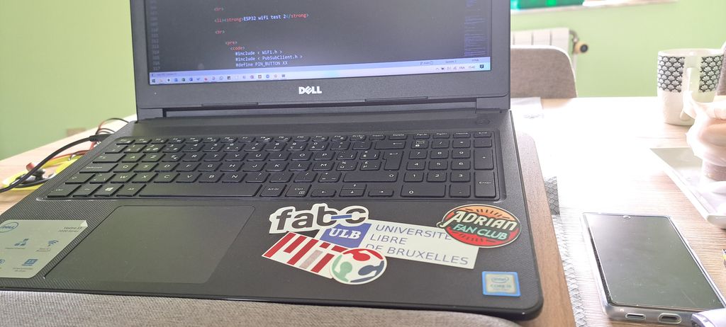
The other one was totally "untouched" by the Fab Academy, so I had to download, upload and install several things to be able to use it :
Neopixel LED ring on 2nd computer
To see if everything is well installed on the 2nd computer, let's run the simple Neopixel code from Arduino (that you can find in the Arduino "File" menu, in the "Examples"):
                          // NeoPixel Ring simple sketch (c) 2013 Shae Erisson
                          // Released under the GPLv3 license to match the rest of the
                          // Adafruit NeoPixel library

                          #include < Adafruit_NeoPixel.h >
                          #ifdef __AVR__
                           #include < avr/power.h > // Required for 16 MHz Adafruit Trinket
                          #endif

                          // Which pin on the Arduino is connected to the NeoPixels?
                          #define PIN        4 // On Trinket or Gemma, suggest changing this to 1

                          // How many NeoPixels are attached to the Arduino?
                          #define NUMPIXELS 16 // Popular NeoPixel ring size

                          // When setting up the NeoPixel library, we tell it how many pixels,
                          // and which pin to use to send signals. Note that for older NeoPixel
                          // strips you might need to change the third parameter -- see the
                          // strandtest example for more information on possible values.
                          Adafruit_NeoPixel pixels(NUMPIXELS, PIN, NEO_GRB + NEO_KHZ800);

                          #define DELAYVAL 1500 // Time (in milliseconds) to pause between pixels

                          void setup() {
                            // These lines are specifically to support the Adafruit Trinket 5V 16 MHz.
                            // Any other board, you can remove this part (but no harm leaving it):
                          #if defined(__AVR_ATtiny85__) && (F_CPU == 16000000)
                            clock_prescale_set(clock_div_1);
                          #endif
                            // END of Trinket-specific code.

                            pixels.begin(); // INITIALIZE NeoPixel strip object (REQUIRED)
                          }

                          void loop() {
                            pixels.clear(); // Set all pixel colors to 'off'

                            // The first NeoPixel in a strand is #0, second is 1, all the way up
                            // to the count of pixels minus one.
                            for(int i=0; i< NUMPIXELS; i++) { // For each pixel...

                              // pixels.Color() takes RGB values, from 0,0,0 up to 255,255,255
                              // Here we're using a moderately bright green color:
                              pixels.setPixelColor(i, pixels.Color(0, 150, 0));

                              pixels.show();   // Send the updated pixel colors to the hardware.

                              delay(DELAYVAL); // Pause before next pass through loop
                            }
                          }
Personal issues
This week I couldn't be at the FabLab to work the assignment with my instructor.
So it was a good challenge for me to try electronics all by myself.
The first exercices with only 1 computer and the ESP32 alone were not so hard to work on and understand.
But starting to work with 2 controllers and 2 computers became harder and I couldn't get the result that was attended.
Right now I'm getting an "access denied" on the 2nd computer that runs the python code.
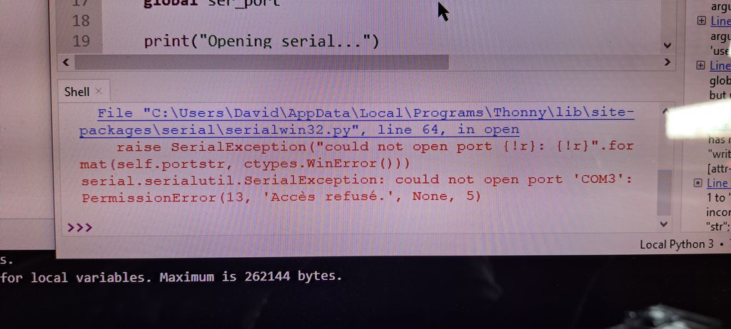
At this moment, this is the only result I have.
This is the work station for this assignment, with both computers (thanks to my husband for sharing its one ! ;) <3 )
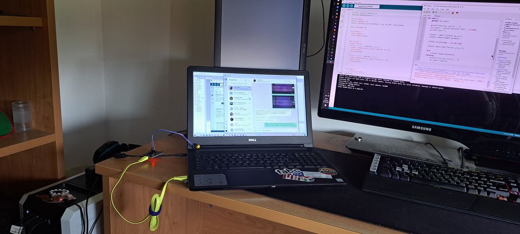
As I'm short (again) in finishing the assignments and documenting before presentation, I will try again tomorrow at the lab with my instructor and document about all this part, fails included, in details afterward.
UPDATE : it was given as advice that it could come frome the "ESP32 chip" and "licence". I will search for that and hopefully be able to use and understand all it correctly as I will need that for my final project !
2ND UPDATE
We've tried the exercice again with my instructor and made it work this time ! Don't ask me why this one's working, I still can't figure it out ! I think it might come from my internet connection at home.
So the goal was to make two ESP32 communicate via WIFI, the first one being the "master" with a button and the second the "slave" with an LED, by switching on the LED of the "slave" using the button of the "master".
I forgot the Neopixel LED Ring so we did it with a single LED.
"Master" ESP32 code
                          #include < WiFi.h >

                          const char* ssid = "XXXXX";
                          const char* password = "XXXXX";
                          const char* host = "XXXXX"; // IP address of the "slave" ESP

                          const int buttonPin = 12;

                          void setup() {
                            Serial.begin(115200);
                            pinMode(buttonPin, INPUT_PULLUP);
                            connectToWiFi();
                          }

                          void loop() {
                            if (digitalRead(buttonPin) == LOW) {
                              sendCommandToSlave("TOGGLE_LED");
                              delay(500); // Delay to avoid button "rebound"
                            }
                          }

                          void connectToWiFi() {
                            Serial.print("Connection to WiFi");
                            WiFi.begin(ssid, password);
                            while (WiFi.status() != WL_CONNECTED) {
                              delay(500);
                              Serial.print(".");
                            }
                            Serial.println("Connected to WiFi!");
                          }

                          void sendCommandToSlave(String command) {
                            WiFiClient client;
                            if (!client.connect(host, 80)) {
                              Serial.println("Fail to connect to server");
                              return;
                            }
                            client.print(command);
                            delay(10);
                            client.stop();
                          }
"Slave" ESP32 code
                          #include < WiFi.h >
                          #include < WiFiClient.h >
                          #include < WiFiAP.h >

                          const char* ssid = "XXXXX";
                          const char* password = "XXXXX";

                          WiFiServer server(80);
                          const int ledPin = 14;
                          bool ledState = LOW;

                          void setup() {
                            Serial.begin(115200);
                            pinMode(ledPin, OUTPUT);
                            connectToWiFi();
                            server.begin();
                          }

                          void loop() {
                            WiFiClient client = server.available();
                            if (!client) {
                              return;
                            }

                            if (client.connected()) {
                              while (client.available() > 0) {
                                String command = client.readStringUntil('\r');
                                if (command == "TOGGLE_LED") {
                                  toggleLED();
                                }
                                delay(10);
                                client.flush();
                              }
                              client.stop();
                            }
                          }

                          void connectToWiFi() {
                            Serial.print("Connection to WiFi");
                            WiFi.begin(ssid, password);
                            while (WiFi.status() != WL_CONNECTED) {
                              delay(500);
                              Serial.print(".");
                            }
                            Serial.println("Connected to WiFi!");

                            Serial.print("Slave ESP IP address : ");
                            Serial.println(WiFi.localIP());
                          }

                          void toggleLED() {
                            ledState = !ledState;
                            digitalWrite(ledPin, ledState);
                          }
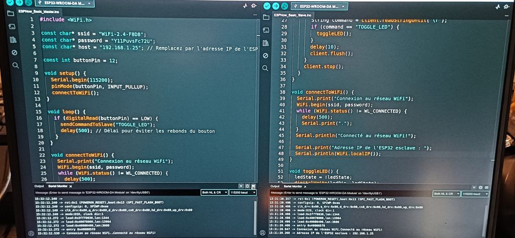
"Master" ESP serial monitor message
Note : I already translated the printed message in the code above so that you just have to copy/paste without thinking about it ! ;) I forgot to do it during the exercice !
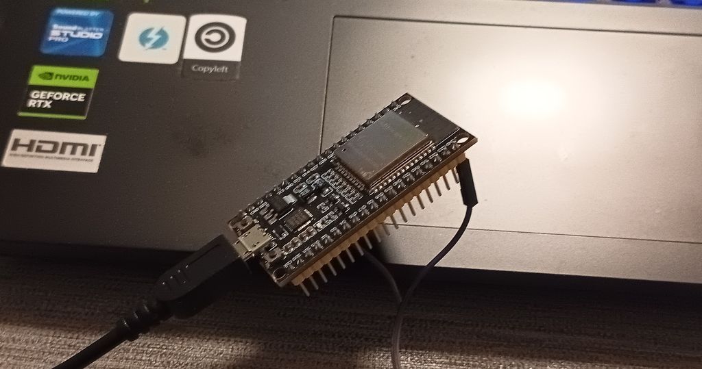

"Slave" ESP serial monitor message
Note : I already translated the printed message in the code above so that you just have to copy/paste without thinking about it ! ;) I forgot to do it during the exercice !
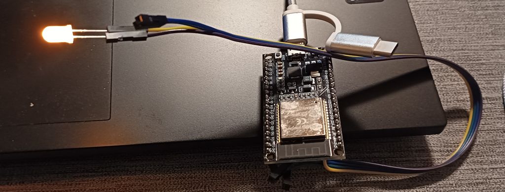

Note : the button component wouldn't work (I'm cursed for this exercice) so we used the wires connection instead. It works the same !
Files and resources
Files
- ESP32 without wifi test code
- ESP32 wifi test 1 code
- ESP32 wifi test 2 code
- 2 ESP32 wifi test slave code
- 2 ESP32 wifi test master code
Resources