4. Electronics Production
This week we learned how to create an electronic board from its cutting on the CNC PCB to soldering the components and finally programming the blinking of a LED light.
Group assignment
Our assignement was to build a microcontroller development "Quentorres" board and make it work by programming the blinking of a LED light
We did several tests to choose the right material and tips.
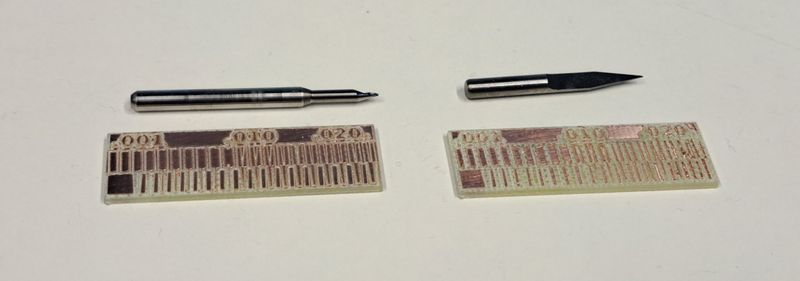
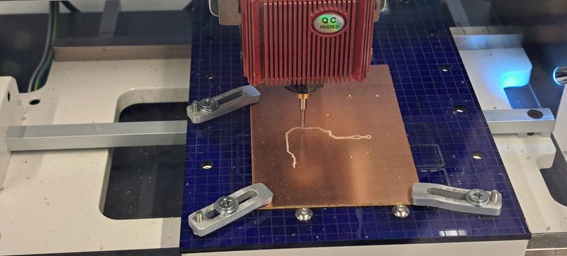
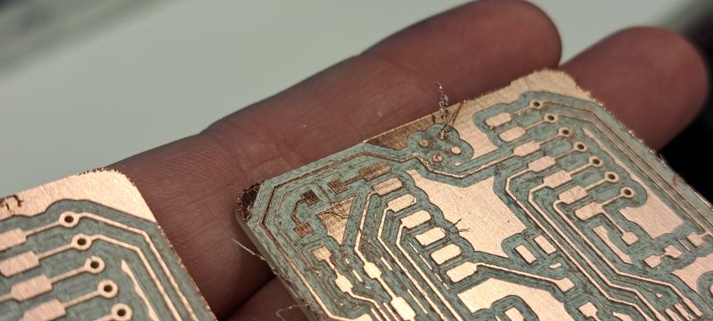
Tip test
We launched a small PCB model on the CNC and used 2 types of tips : a "V" one and an "helocoidal" one.
As you can see below, the helicoidal tip is giving a much better and precise result than the "V" one.
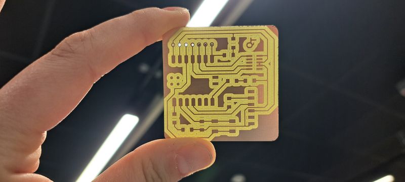
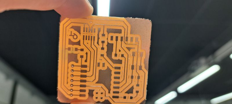
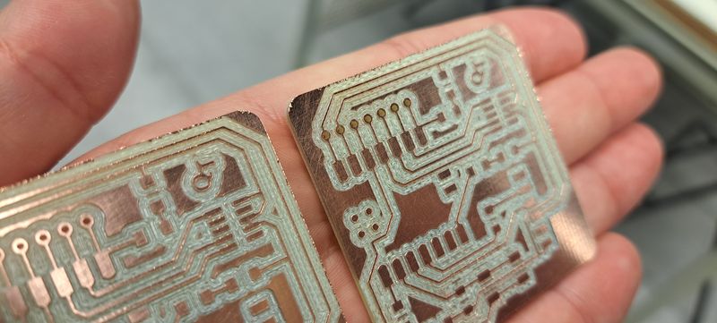
Material test
We also tried out the Quentorres board on 2 different materials : FR1 (phenolic paper) and FR4 (epoxy glass).
The Epoxy Glass (first picture below) gives a much better result, that's why we used it to complete this assignment.
Preparing the G-Code files
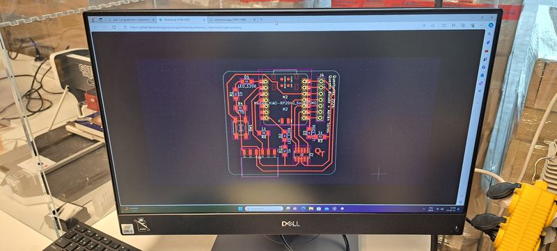
To get the Quentorres board cut and engraved, we had to prepare the G-Code files that will run the CNC to get the physical base of the board (without its components).
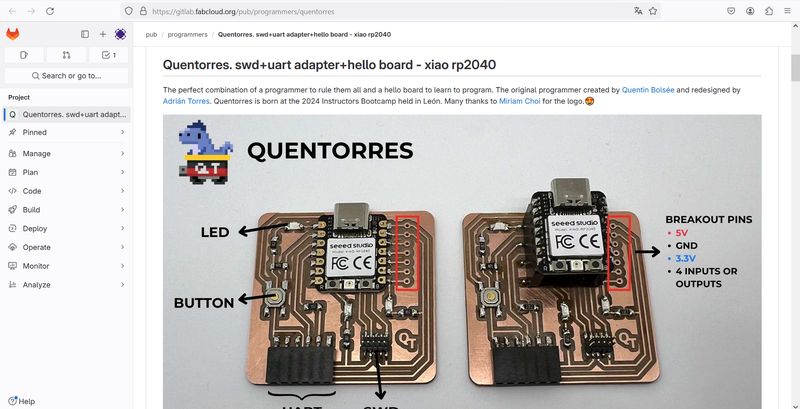
We prepared the G-Code files in Mods.
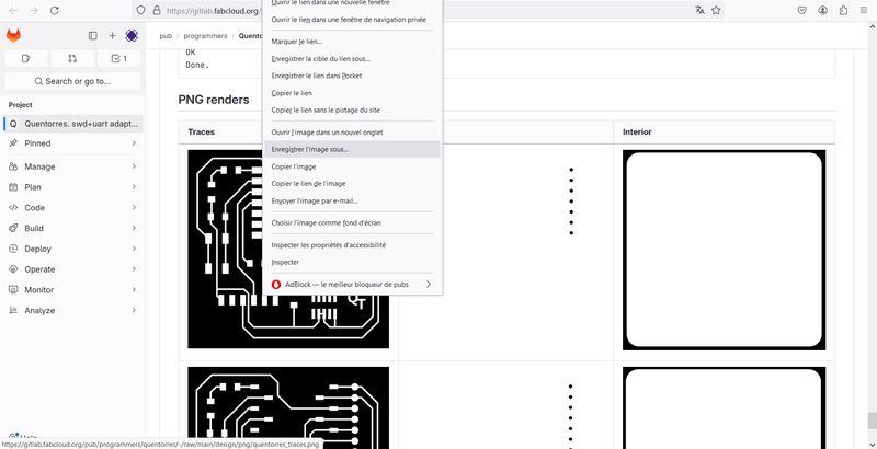
For that, we saved the Quentorres PNG files that are in the Fabcloud (no need to rename the files).
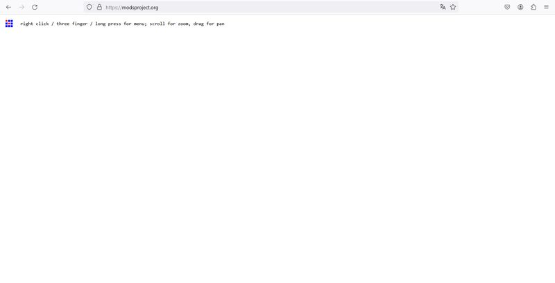
Discovering Mods
The Mods website is simple to use and has a minimalist interface.
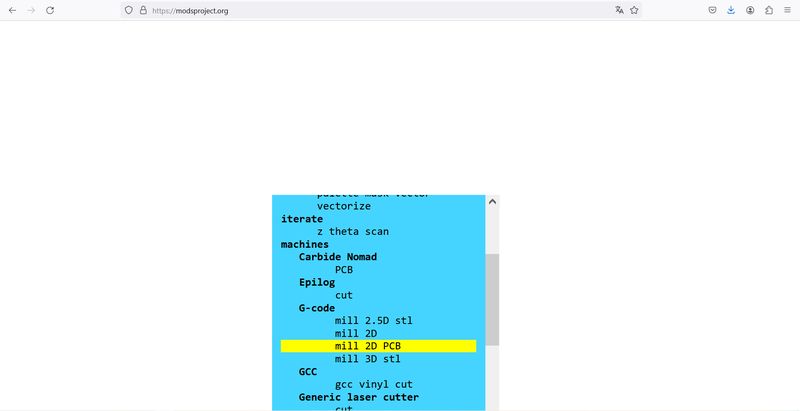
To create the G-Code files, you have to right-click on the interface and choose "G-Code > mill 2D PCB". This will open all the parameters you'll need to configure the Quentorres PCB cutting and engraving.
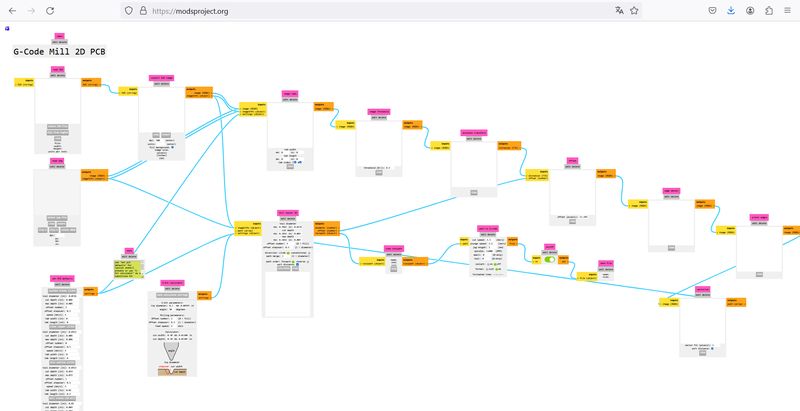
First we worked on the "traces" file by opening it in the "read png" box.
To create the traces, we had to insert the path parameters in the "path to G-code" box.
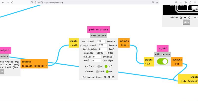
- cut speed : 175
- plunge speed : 175
- jog height : 2
- spindle : 11000
- dwell : 0
- tool : 0
- coolant : off
- format : mm
Then we changed the mill raster parameters in the "mill raster 2D" box.
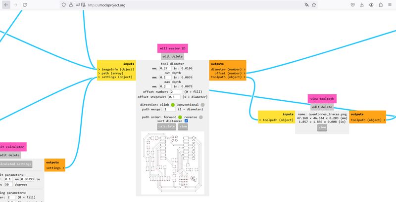
- tool diameter : 0.27mm
- cut depth : 0.1mm
- max depth : 0.2mm
- offset number : 2
- offset stepover : 0.5
- direction : climb
- path merge : 1
- path order : forward
- sort distance : checked
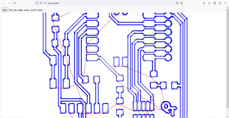
After entering all the parameters, clicking on "Calculate" (in the bottom of the "mill raster 2D" box) will generate the G-Code file and open a view of the result. This shows where the tool will engrave.
After the "traces" file, we did the same for the "drill" file and changed the path parameters by :
- cut speed : 175
- plunge speed : 175
- jog height : 2
- spindle : 11000
- dwell : 0
- tool : 0
- coolant : off
- format : mm
And the mill raster 2D parameters by :
- tool diameter : 0.8mm
- cut depth : 1mm
- max depth : 1.35mm
- offset number : 1
- offset stepover : 0.5
- direction : climb
- path merge : 1
- path order : forward
- sort distance : checked
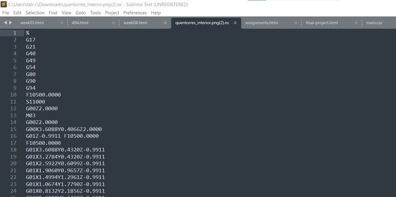
Here's how a G-Code looks like when you open it in a simple text computer program :
Last but not least, we opened the "interior" file and also changed the parameters.
Here are the path parameters :
- cut speed : 175
- plunge speed : 175
- jog height : 2
- spindle : 11000
- dwell : 0
- tool : 0
- coolant : off
- format : mm
And the mill raster 2D parameters :
- tool diameter : 1mm
- cut depth : 1mm
- max depth : 1.35mm
- offset number : 1
- offset stepover : 0.5
- direction : climb
- path merge : 1
- path order : forward
- sort distance : checked
Engraving, drilling and cutting the board with the CNC
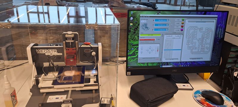
The CNC we have for PCB boards is a Wegstr.
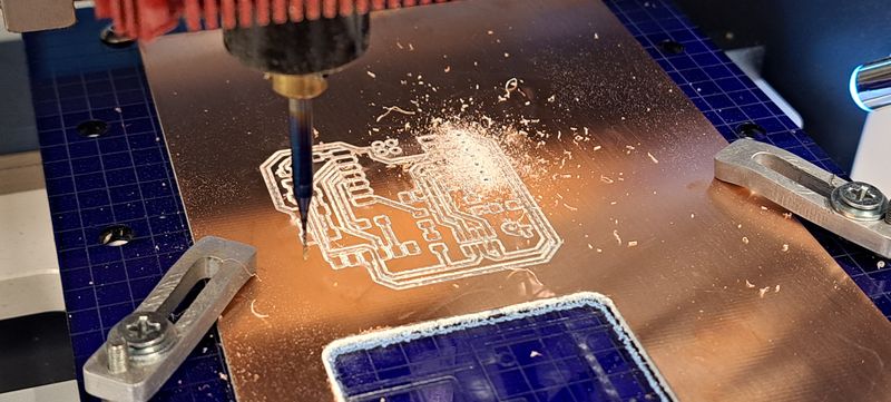
To get the finished Quentorres board, we have to start by the engraving part.
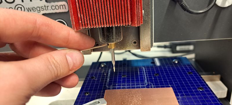
First we had to change the tip and insert a 0.27mm helicoidal one .
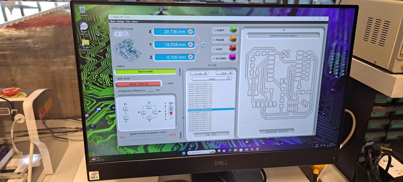
Then to open the G-Code file on the Wegstr computer program.
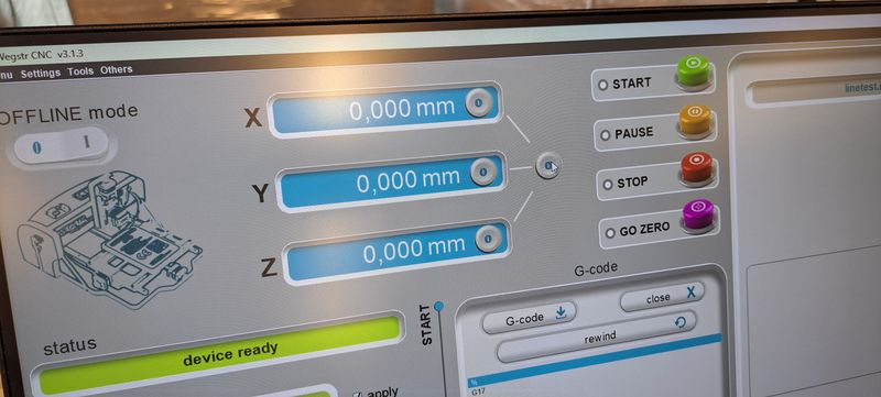
We had to configure the "zero" level on the Z-axis of the machine by connecting a little cable and move the Z-axis until the light goes on.
After that, we checked the level every 5 mm on the plate by using the "auto-level" option so that the machine remembers where the levels change a bit and will adjust by itself during the engraving process.
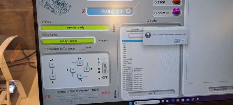
When we were sure that every basic parameter was ok, we launched the machine.
Next step was the drill part of the board. We had to change the tip to a 0.8mm one and calculate again the "zero" level of the Z-axis. We could then launch the machine.
Last step, the cutting of the board with the 1mm helicoidal tip.
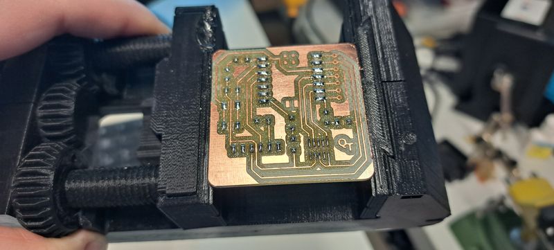
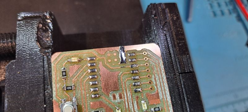
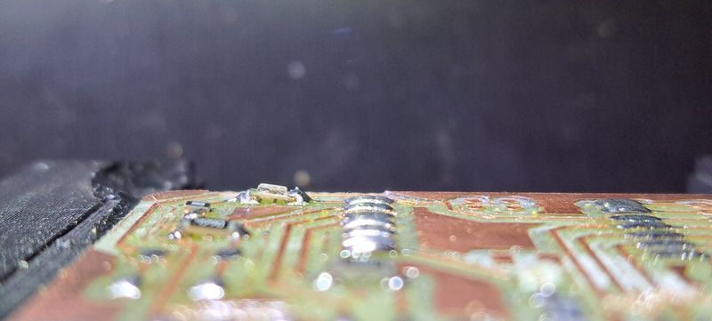
The result looks pretty good but the boards will need to be cleaned to get all the little copper pieces off.
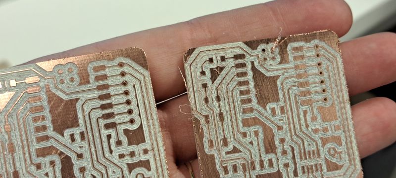
Here's the final result after cleaning.
UPDATE
I've never thought that creating a PCB was so easy ! (let's undertand ourselves, right now I'm talking about the CNC part, when you've already have a design ! Thanks again Adrian and Quentin ^^)
It's astounishing how the CNC can be so precise. At first I was a bit afraid to rub the toothbrush on it while cleaning because I thought the lines would come off but they didn't !
And even though Mods is a real mystery, especially weird when you open it and there's nearly nothing on the screen, it really is effective and not so hard to use when you know it a bit.
But I'd still be amazed of the people who created it ! There must be such a work behind it.
Link to our Group week 4 page
Individual assignment
Soldering the components
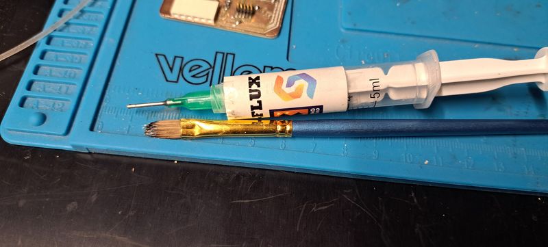
Time to solder the components to the board.
To be sure that the wire won't spread everywhere, we put some flux on it.
Then we put some wire on each piece of the board that will get a component solder on it. For that, we checked the board design file to be sure to put it on the right places.
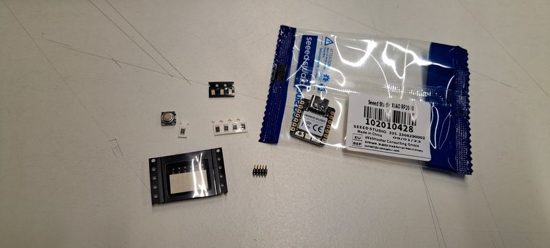
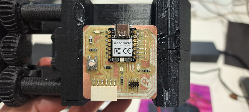
When the board was ready, we started adding the components :
- 1. the resistors
- 2. the leds
- 3. the button
- 4. the 6 Position Receptacle Connector
- 5. the 10 Position Receptacle Connector
- 6. the SEEED STUDIO XIAO RP2040 ARDUINO
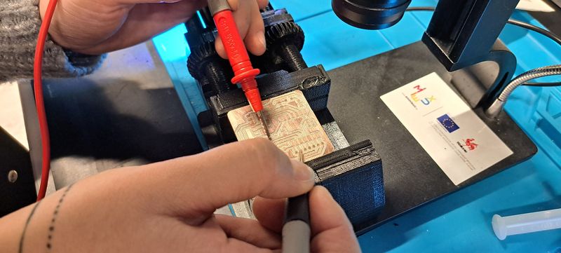
To check the connections before connecting the board to a computer, we used a multimeter.
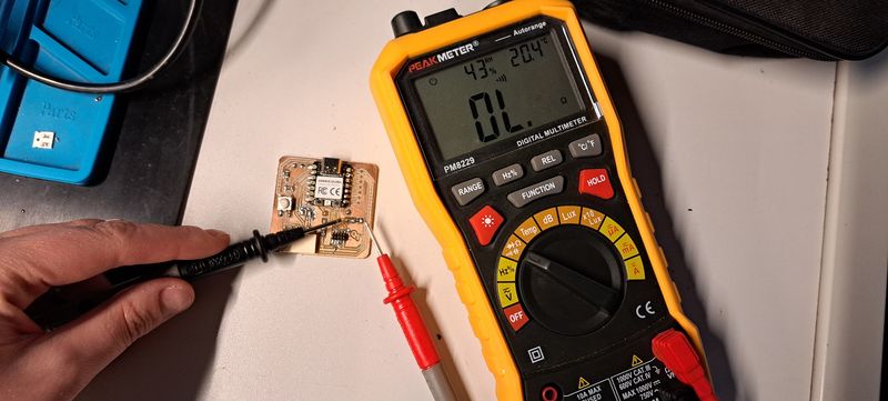
Little failure
Soldering little pieces like these isn't so easy. You have to practice to get the right amount of wire and to place the components correctly.
I learned for example to be more careful at the time a big piece of wire fell right on the board, of course where it didn't belong... Fortunately, the Seeed Studio piece covered it and we took off most of it with braid.
As a perfectionist, I'm also frustrated that the pieces don't lay flat on the board. That's because of a wrong amount of wire beneath them.
Connecting the board and launching the blinking program
The board is ready and the connection was successfull ! YAY !

Time to install Arduino and code the led blinking program.
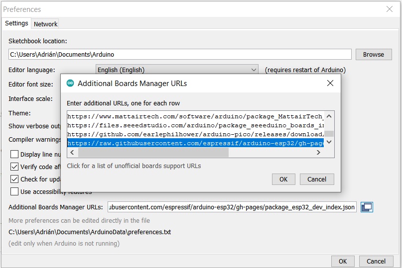
In File->Preferences, we had to add the URL of the additional boards, the Arduino-Pico by Earlephilhower.
The next step was to download Pico in the boards manager by going in Tools->Board->Board manager
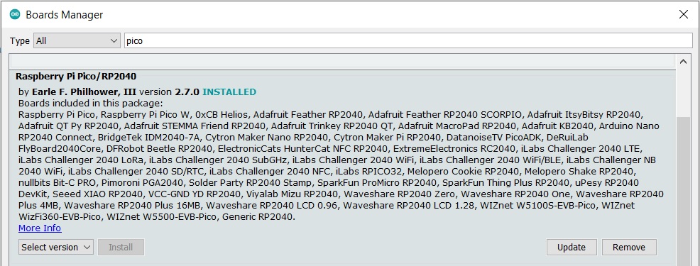
Then we configured the Arduino IDE for the Seeed Studio XIAO RP2040. The Seeed Studio XIAO RP2040 will appear in the COM port.
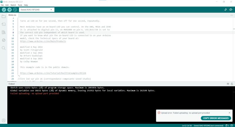
Small issue The first cable we used seemed to malfunction. But after trying with another one, we found out that it was because the COM port wasn't selected...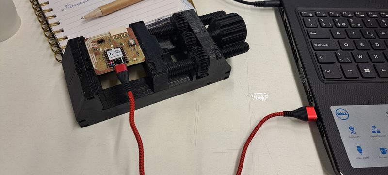
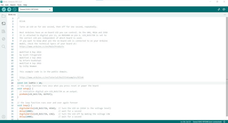
We loaded the Blink program so that the LED on pin 26 blinks every second. It worked well.
                          /*
                            Blink

                            Turns an LED on for one second, then off for one second, repeatedly.

                            Most Arduinos have an on-board LED you can control. On the UNO, MEGA and ZERO
                            it is attached to digital pin 13, on MKR1000 on pin 6. LED_BUILTIN is set to
                            the correct LED pin independent of which board is used.
                            If you want to know what pin the on-board LED is connected to on your Arduino
                            model, check the Technical Specs of your board at:
                            https://www.arduino.cc/en/Main/Products

                            modified 8 May 2014
                            by Scott Fitzgerald
                            modified 2 Sep 2016
                            by Arturo Guadalupi
                            modified 8 Sep 2016
                            by Colby Newman

                            This example code is in the public domain.

                            https://www.arduino.cc/en/Tutorial/BuiltInExamples/Blink
                          */
                          //lire led sur pin 26 (correspondance composante seeed studio)
                          const int ledPin = 26;
                          // the setup function runs once when you press reset or power the board
                          void setup() {
                            // initialize digital pin LED_BUILTIN as an output.
                            pinMode(ledPin, OUTPUT);
                          }

                          // the loop function runs over and over again forever
                          void loop() {
                            digitalWrite(ledPin, HIGH);  // turn the LED on (HIGH is the voltage level)
                            delay(1000);                      // wait for a second
                            digitalWrite(ledPin, LOW);   // turn the LED off by making the voltage LOW
                            delay(1000);                      // wait for a second
                          }
Some extra
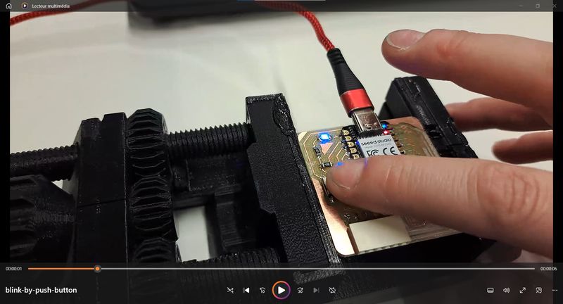
We tried out another program to also use the button on the board.
For that, we asked Gemini from Google to help us create the program and it worked.

By pushing the button, the LED goes on. When we release the pression on the button, it goes off.
                          // Définition des broches
                        const int boutonPin = 27;
                        const int ledPin = 26;

                        void setup() {
                          // Configuration du bouton en entrée
                          pinMode(boutonPin, INPUT);

                          // Configuration de la LED en sortie
                          pinMode(ledPin, OUTPUT);

                          // Démarrage de la LED éteinte
                          digitalWrite(ledPin, LOW);
                        }

                        void loop() {
                          // Lecture de l'état du bouton
                          int etatBouton = digitalRead(boutonPin);

                          // Si le bouton est appuyé
                          if (etatBouton == HIGH) {
                            // Allumer la LED
                            digitalWrite(ledPin, HIGH);
                          } else {
                            // Eteindre la LED
                            digitalWrite(ledPin, LOW);
                          }
                        }
Here is the prompt we used in french :
code arduino seeed rp2040 bouton pin 27, led pin 26. Quand on appuie sur le bouton, la led s'allume
Translation in english :
code arduino seeed rp2040 button pin 27, led pin 26. When the button is pressed, the led lights up.
My journey
This was a new skill to learn and I enjoyed it !
I mostly enjoyed the soldering of the components, even though it wasn't so easy.
The pieces are so small that I've lost one by pinching it to hard with the pliers... (and I fortunately found it a bit later !)
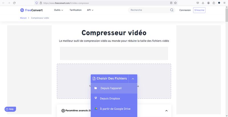
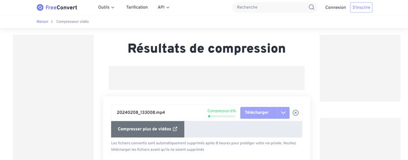
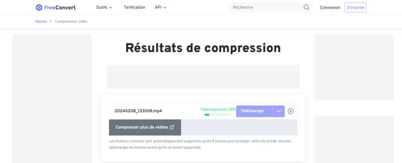
To add the success of the assignment by video, I tried out a video converter I found by searching on the internet.
The website is called Freeconvert
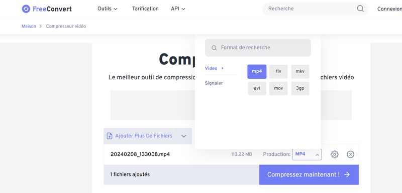
Simple to use, you can choose the format you want, if you want to compress by rate or to a fixed size (what I did) and to add or remove subtitles.
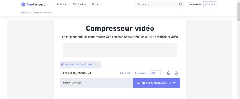
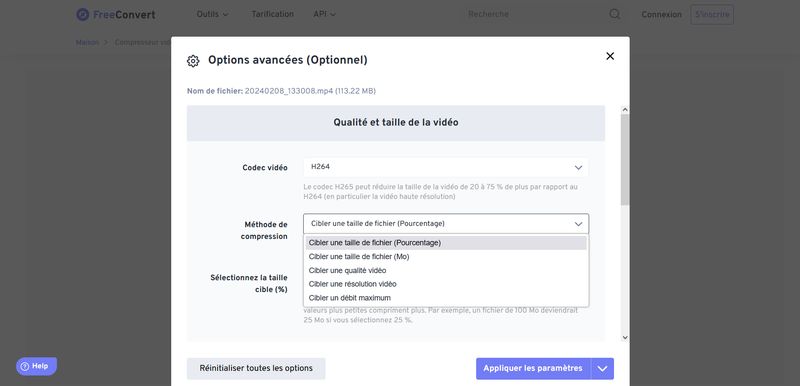
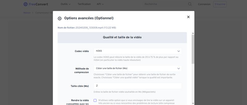
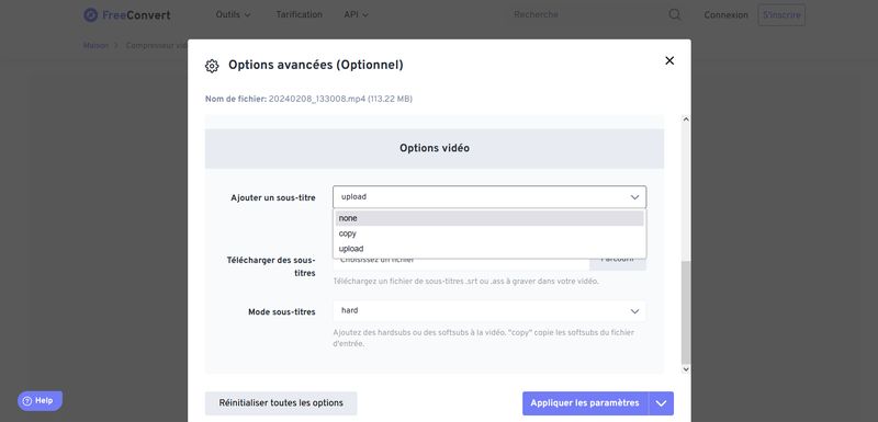
I had to try out several options or sizes to find the best quality and for some videos I finally decided to cut them with the simple "photos view" program that's already on Windows.
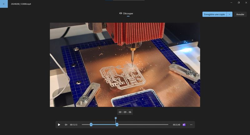
Here's is a picture of a bad quality.
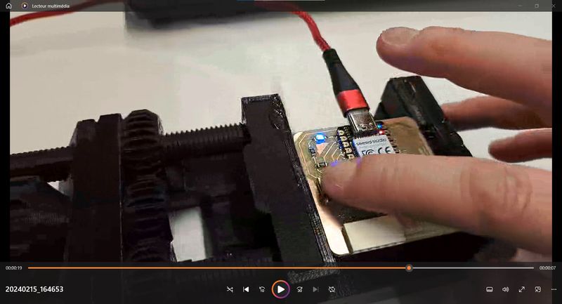
Here's is a picture of the same video with a better quality.
My Final Project
I'm still searching for inspiration for the base, structure, size and accessories of the modular pet house.
I've found some more picture of existing models that I keep in a folder.
Files and resources
My files
- Traces PNG
- Drill PNG
- Interior PNG
- Traces G-Code
- Drill G-Code
- Interior G-Code
- Arduino LED blinking
- Arduino LED light by pushing button
Resources