6. Embedded Programming
This week we programmed the Quentorres, tried another programming language and browsed through a data sheet.
Group assignment
Browsing through a data sheet and comparing the performance and development workflows for other architectures were on our to-do list.
Seeed Studio XIAO RP2040
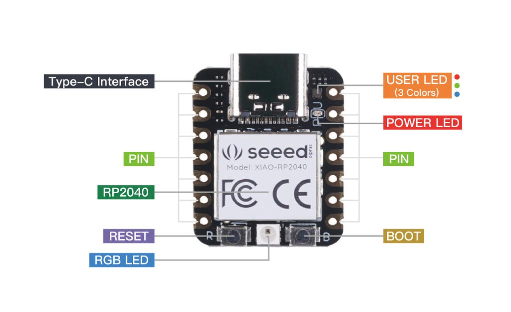
Features
- Powerful MCU: Dual-core ARM Cortex M0+ processor, flexible clock running up to 133 MHz
- Rich on-chip resources: 264KB of SRAM, and 2MB of on-board Flash memory
- Flexible compatibility: Support Micropython/Arduino/CircuitPython
- Easy project operation: Breadboard-friendly & SMD design, no components on the back
- Small size: As small as a thumb(20x17.5mm) for wearable devices and small projects.
- Multiple interfaces: 11 digital pins, 4 analog pins, 11 PWM Pins,1 I2C interface, 1 UART interface, 1 SPI interface, 1 SWD Bonding pad interface.
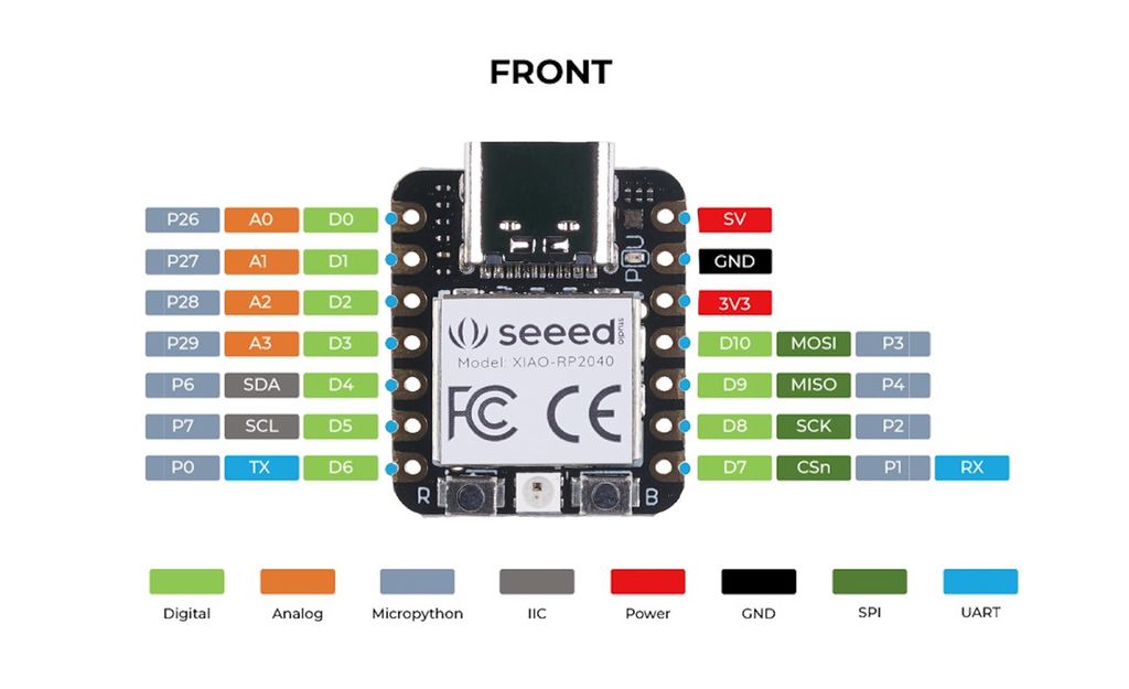
Specifications
| Item | Value |
|---|---|
| CPU | Dual-core ARM Cortex M0+ processor up to 133MHz |
| Flash Memory | 2MB |
| SRAM | 264KB |
| Digital I/O Pins | 11 |
| Analog I/O Pins | 4 |
| PWM Pins | 11 |
| I2C interface | 1 |
| SPI interface | 1 |
| UART interface | 1 |
| Power supply and downloading interface | Type-C |
| Power | 3.3V/5V DC |
| Dimensions | 20×17.5×3.5mm |
In this state, the Seeed Studio has 11 pins free to be used and an in- and/or output.
When we use it in the Quentorres, only 4 pins are left available and the in- and/or output.
UPDATE - ESP32 NODEMCU Module WiFi Development Board with CP2102
This one will be used in week 13 and in my final project
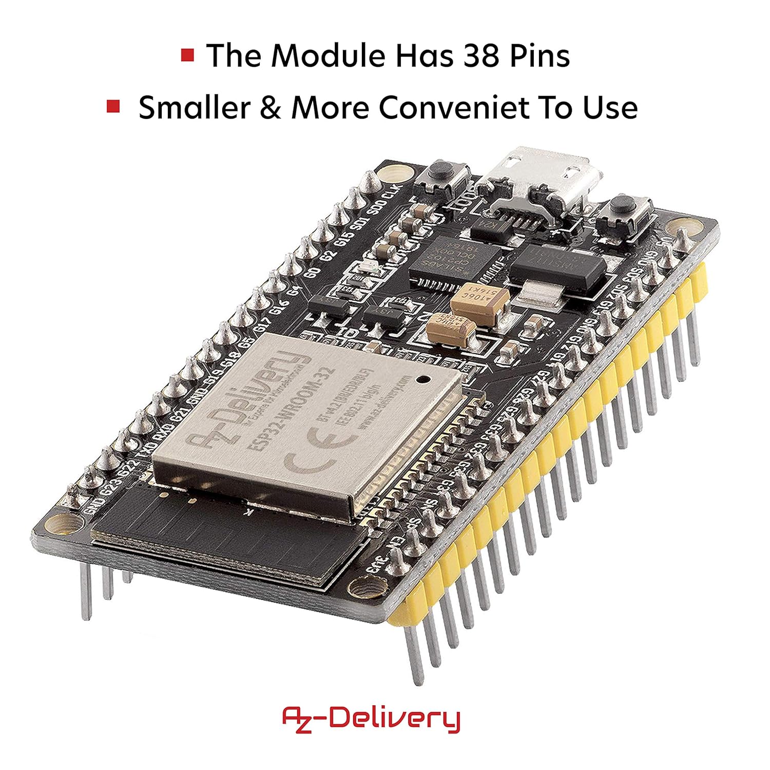
Features
- As with the predecessor model ESP8266, the WLAN functionality is implemented directly in the SoC, but with additional Bluetooth function (incl. BLE).
- The ESP32 processor used combines a CPU with 2 Tensilica LX6 cores, clocked at up to 240 MHz, and 512 kiloBytes of SRAM in a single microcontroller chip.
- It also integrates a radio unit for WLAN (according to 802.11bgn) and Bluetooth (Classic and LE).
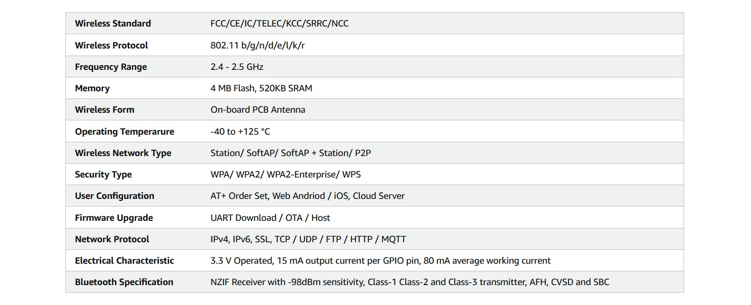
Specifications
| Item | Value |
|---|---|
| Power supply voltage (USB) | 5V |
| Input/output voltage | 3.3V |
| Required operating current | Min. 500mA |
| Soc | ESP32-Wroom 32 |
| Clock frequency range | 80MHz / 240MHz |
| RAM | 512kb |
| External flash memory | 4MB |
| I/o pins | 34 |
| Interfaces | SPI, I2C, I2S, Can, Uart |
| Wi-fi protocols | 802.11 b/g/n (802.11n up to 150 Mbps) |
| Wi-fi frequency | 2.4 GHz - 2.5 GHz |
| Bluetooth | V4.2 - BLE and Classic Bluetooth |
| Wireless antenna | PCB |
| Dimensions | 56x28x13mm |
Link to our Group week 6 page
Individual assignment
Quentorres programming
We've already programmed the led to blink by pushing the button on the Quentorres on week04.
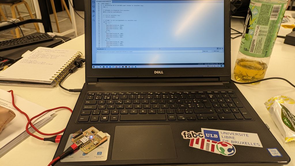
This week we went a little further !
First we programmed the 3 leds to blink all at ones every second with Arduino.
                        //read leds on pin 26, 0 and 1(correspondance seeed studio component)
                        const int ledPin0 = 26;
                        const int ledPin1 = 0;
                        const int ledPin2 = 1;
                        // the setup function runs once when you press reset or power the board
                        void setup() {
                          // initialize digital pins as an output.
                          pinMode(ledPin0, OUTPUT);
                          pinMode(ledPin1, OUTPUT);
                          pinMode(ledPin2, OUTPUT);
                        }

                        // the loop function runs over and over again forever
                        void loop() {
                          digitalWrite(ledPin0, HIGH);  // turn the LEDs on (HIGH is the voltage level)
                          digitalWrite(ledPin1, HIGH);
                          digitalWrite(ledPin2, HIGH);
                          delay(1000);                      // wait for a second
                          digitalWrite(ledPin0, LOW);  // turn the LEDs off (LOW is the voltage level)
                          digitalWrite(ledPin1, LOW);
                          digitalWrite(ledPin2, LOW);
                          delay(1000);                      // wait for a second
                        }
The next step was to use the button again and turn the 3 leds on all at ones by pushing it.
                        // Defining the pins
                        const int boutonPin = 27;
                        const int ledPin0 = 26;
                        const int ledPin1 = 0;
                        const int ledPin2 = 1;

                        void setup() {
                          // Configure the button as INPUT
                          pinMode(boutonPin, INPUT);

                          // Configure the LEDs as OUTPUT
                          pinMode(ledPin0, OUTPUT);
                          pinMode(ledPin1, OUTPUT);
                          pinMode(ledPin2, OUTPUT);

                          // Starting with the LEDs turned off
                          digitalWrite(ledPin0, LOW);
                          digitalWrite(ledPin1, LOW);
                          digitalWrite(ledPin2, LOW);
                        }

                        void loop() {
                          // Reading the button's state
                          int etatBouton = digitalRead(boutonPin);

                          // If the button is pushed
                          if (etatBouton == HIGH) {
                            // Turn on the LEDs
                            digitalWrite(ledPin0, HIGH);
                            digitalWrite(ledPin1, HIGH);
                            digitalWrite(ledPin2, HIGH);
                          } else {
                            // Turn off the LEDs
                            digitalWrite(ledPin0, LOW);
                            digitalWrite(ledPin1, LOW);
                            digitalWrite(ledPin2, LOW);
                          }
                        }
Last step, I used the Arduino Serial Monitor to turn on and off the LEDs separately.
For this program, I asked Gemini (Google's ChatGPT) for some help (because I'm no good at programming!) and it gave me this code :
                        // Defining LEDs pins
                        #define LED_26 26
                        #define LED_1 1
                        #define LED_0 0

                        void setup() {
                          // Initialize LEDs pins as OUTPUT
                          pinMode(LED_26, OUTPUT);
                          pinMode(LED_1, OUTPUT);
                          pinMode(LED_0, OUTPUT);

                          //  Starting Serial Monitor
                          Serial.begin(9600);
                        }

                        void loop() {
                          // Declaring the variable that will stock the received character
                          char c;

                          // Waiting to receive the character
                          while (!Serial.available());

                          // Reading the received character
                          c = Serial.read();

                          // The LED that corresponds to the received character lights up
                          switch (c) {
                            case '1':
                              digitalWrite(LED_26, HIGH);
                              digitalWrite(LED_1, LOW);
                              digitalWrite(LED_0, LOW);
                              break;
                            case '2':
                              digitalWrite(LED_26, LOW);
                              digitalWrite(LED_1, HIGH);
                              digitalWrite(LED_0, LOW);
                              break;
                            case '3':
                              digitalWrite(LED_26, LOW);
                              digitalWrite(LED_1, LOW);
                              digitalWrite(LED_0, HIGH);
                              break;
                            case '0':
                              digitalWrite(LED_26, LOW);
                              digitalWrite(LED_1, LOW);
                              digitalWrite(LED_0, LOW);
                              break;
                          }
                        }
It results on :
- turning on LED 26 by writing "1" in the serial monitor,
- turning on LED 1 by writing "2" in the serial monitor,
- turning on LED 0 by writing "3" in the serial monitor,
- turning all LEDs off by writing "0" in the serial monitor.
Here is the prompt I used in Gemini to get the code :
code arduino serial monitor seeed rp2040 led pin 26, led pin1 and led pin0. When "1" is written in the serial monitor, led pin 26 lights up. When "2" is written in the serial monitor, led pin 1 lights up. When "3" is written in the serial monitor, led pin 0 lights up. When "0" is written in the serial monitor, all 3 leds go out.
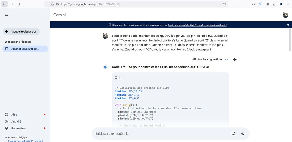
As little extra, I installed and tried out Thonny to code in MicroPython.
For that, I followed all the steps of the Seeed Studio wiki page MicroPython language to get the RGB LED to blink in "Beautiful colors".
So, after installing the Thonny Editor and connecting the Seeed Studio, it is asked to download the ws2812.py library, open it in the Editor and save it on the "Raspberry Pi Pico".
Here is the ws2812.py library content :
                          import array, time
                          from machine import Pin
                          import rp2

                          # Configure the number of WS2812 LEDs.
                          #brightness = 0.2
                          @rp2.asm_pio(sideset_init=rp2.PIO.OUT_LOW, out_shiftdir=rp2.PIO.SHIFT_LEFT, autopull=True,pull_thresh=24)
                          def ws2812():
                              T1 = 2
                              T2 = 5
                              T3 = 3
                              wrap_target()
                              label("bitloop")
                              out(x, 1) .side(0) [T3 - 1]
                              jmp(not_x, "do_zero") .side(1) [T1 - 1]
                              jmp("bitloop") .side(1) [T2 - 1]
                              label("do_zero")
                              nop() .side(0) [T2 - 1]
                              wrap()
                          class WS2812():
                              def __init__(self, pin_num, led_count, brightness = 0.5):
                                  self.Pin = Pin
                                  self.led_count = led_count
                                  self.brightness = brightness
                                  self.sm = rp2.StateMachine(0, ws2812, freq=8_000_000, sideset_base=Pin(pin_num))
                                  self.sm.active(1)
                                  self.ar = array.array("I", [0 for _ in range(led_count)])

                              def pixels_show(self):
                                  dimmer_ar = array.array("I", [0 for _ in range(self.led_count)])
                                  for i,c in enumerate(self.ar):
                                      r = int(((c >> 8) & 0xFF) * self.brightness)
                                      g = int(((c >> 16) & 0xFF) * self.brightness)
                                      b = int((c & 0xFF) * self.brightness)
                                      dimmer_ar[i] = (g<<16) + (r<<8) + b
                                  self.sm.put(dimmer_ar, 8)
                                  time.sleep_ms(10)

                              def pixels_set(self, i, color):
                                  self.ar[i] = (color[1]<<16) + (color[0]<<8) + color[2]

                              def pixels_fill(self, color):
                                  for i in range(len(self.ar)):
                                      self.pixels_set(i, color)

                              def color_chase(self,color, wait):
                                  for i in range(self.led_count):
                                      self.pixels_set(i, color)
                                      time.sleep(wait)
                                      self.pixels_show()
                                  time.sleep(0.2)
                              def wheel(self, pos):
                              # Input a value 0 to 255 to get a color value.
                              # The colours are a transition r - g - b - back to r.
                                  if pos < 0 or pos > 255:
                                      return (0, 0, 0)
                                  if pos < 85:
                                      return (255 - pos * 3, pos * 3, 0)
                                  if pos < 170:
                                      pos -= 85
                                      return (0, 255 - pos * 3, pos * 3)
                                  pos -= 170
                                  return (pos * 3, 0, 255 - pos * 3)


                              def rainbow_cycle(self, wait):
                                  for j in range(255):
                                      for i in range(self.led_count):
                                          rc_index = (i * 256 // self.led_count) + j
                                          self.pixels_set(i, self.wheel(rc_index & 255))
                                      self.pixels_show()
                                      time.sleep(wait)
Then I had to open a new file and paste this code in it :
                          from ws2812 import WS2812
                          import utime
                          import machine
                          power = machine.Pin(11,machine.Pin.OUT)
                          power.value(1)
                          BLACK = (0, 0, 0)
                          RED = (255, 0, 0)
                          YELLOW = (255, 150, 0)
                          GREEN = (0, 255, 0)
                          CYAN = (0, 255, 255)
                          BLUE = (0, 0, 255)
                          PURPLE = (180, 0, 255)
                          WHITE = (255, 255, 255)
                          COLORS = (BLACK, RED, YELLOW, GREEN, CYAN, BLUE, PURPLE, WHITE)

                          led = WS2812(12,1)#WS2812(pin_num,led_count)

                          while True:
                              print("Beautiful color")
                              for color in COLORS:
                                  led.pixels_fill(color)
                                  led.pixels_show()
                                  utime.sleep(0.2)
Finally, this code has to be uploaded by clicking the "Run current script" button. The location where it will be saved is not important. Both locations are fine.
If it works well, you will see the RGB LED light convert and flash the lights. And the output of the text "Beautiful Color" will as well be displayed in the Shell.
Files and resources
My files
- Arduino file 3 leds blinking
- Arduino file 3 leds blinking with button pushed
- Arduino file leds on/off with serial monitor
- ws2812.py library for Thonny Editor
Resources