11. Input Devices
Hero shot
Group Assignment
Measuring HC-SR04 Ultrasonic sensor (infos from Components 101)
This sensor is a very popular sensor used in many applications where measuring distance or sensing objects are required.
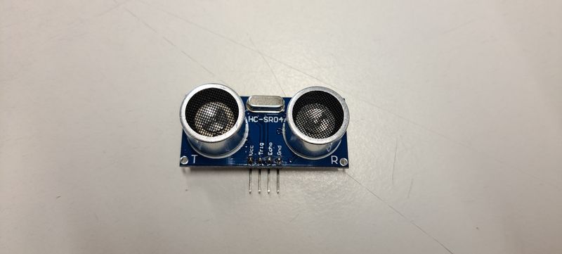
The module has two eyes like projects in the front which forms the Ultrasonic transmitter and Receiver.
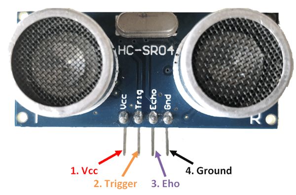
It is a 4 pin module, whose pin names are Vcc, Trigger, Echo and Ground respectively.
Applications
- Used to avoid and detect obstacles with robots like biped robot, obstacle avoider robot, path finding robot etc.
- Used to measure the distance within a wide range of 2cm to 400cm
- Can be used to map the objects surrounding the sensor by rotating it
- Depth of certain places like wells, pits etc can be measured since the waves can penetrate through water
Test with the Ultrasonic Sensor (from Project Hub Arduino)
                          /*
                         * HC-SR04 example sketch
                         *
                         * https://create.arduino.cc/projecthub/Isaac100/getting-started-with-the-hc-sr04-ultrasonic-sensor-036380
                         *
                         * by Isaac100
                         */

                        //define the pins that Trig and Echo are connected to
                        const int trigPin = 2;
                        const int echoPin = 1;

                        //declare 2 floats, duration and distance, which will hold the length of the sound wave and how far away the object is
                        float duration, distance;

                        void setup() {
                          pinMode(trigPin, OUTPUT); //declare the Trig pin as an output
                          pinMode(echoPin, INPUT); //declare the Echo pin as an input
                          Serial.begin(9600); //start Serial communications
                        }

                        void loop() {
                          digitalWrite(trigPin, LOW); //set the trigPin low for 2 microseconds just to make sure
                          delayMicroseconds(2); //that the pin in low first
                          digitalWrite(trigPin, HIGH);
                          delayMicroseconds(10);
                          digitalWrite(trigPin, LOW);

                          duration = pulseIn(echoPin, HIGH);
                          distance = (duration*.0343)/2;
                          Serial.print("Pulse: ");
                          Serial.print(duration);
                          Serial.println("micro seconds");
                          Serial.print("Distance: ");
                          Serial.print(distance);
                          Serial.println("cm");
                          Serial.println(" ");

                          delay(1000);
                        }
Link to our Group page
Individual Assignment
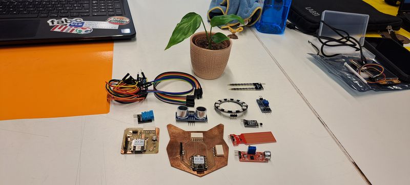
I've tested several input devices with programming codes found on internet to understand how they work and how useful they could be (mostly for my final project).
Humidity and Temperature Sensor (infos from Tuto Duino)
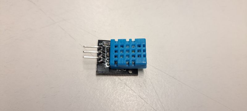
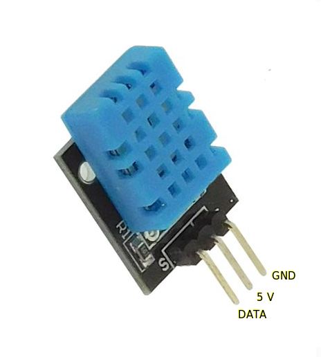
The DHT11 sensor measures temperature and humidity. The use of this type of sensor is interesting for a beginner because it makes it possible to measure a physical quantity accessible to all.
Pinouts
The DHT11 sensor has 4 pins, but is often sold on a carrier board which has 3 pins. It communicates with the Arduino very simply through one of its digital inputs. The other 2 pins are for its 5V supply and ground (GND).
Test with the Humidity and Temperature Sensor
                          #include < DHT.h>
                          #define DHTPIN 9
                          #define DHTTYPE DHT11
                          DHT dht(DHTPIN, DHTTYPE);
                          float temp;
                          float hum;
                          void setup() {
                          Serial.begin(9600);
                          dht.begin();
                          }

                          void loop() {
                            hum = dht.readHumidity();
                            temp = dht.readTemperature();
                            if (isnan(hum) || isnan(temp)) {
                              Serial.println("Error reading from DHT sensor!");
                              return;
                            }
                            Serial.print("Humidity: ");
                            Serial.print(hum);
                            Serial.print("%\t");
                            Serial.print("Temperature: ");
                            Serial.print(temp);
                            Serial.println(" *C");
                            delay(2000);
                          }
Water Level Sensor
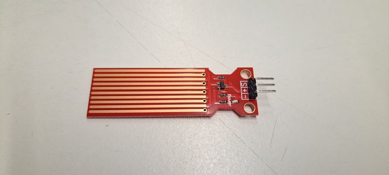
Water Level Sensor Pinout (infos form Arduino Get Started)
The water level sensor has 3 pins:
- S (Signal) pin: is an analog output that will be connected to one of the analog inputs on your Arduino.
- + (VCC) pin: supplies power for the sensor. It is recommended to power the sensor with between 3.3V – 5V.
- - (GND) pin: is a ground connection.
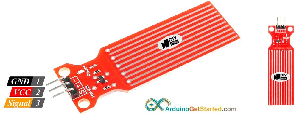
The analog output value on the signal pin varies depending on the voltage supplied to the VCC pin of the sensor.
How Water Level Sensor Works
Simply, The more water the sensor is immersed in, the higher the output voltage in the signal pin is.
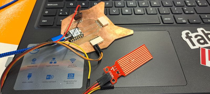
Test with the Water Sensor
                          /*
                         * Created by ArduinoGetStarted.com
                         *
                         * This example code is in the public domain
                         *
                         * Tutorial page: https://arduinogetstarted.com/tutorials/arduino-water-sensor
                         */

                        #define POWER_PIN  14
                        #define SIGNAL_PIN A0

                        int value = 0; // variable to store the sensor value

                        void setup() {
                          Serial.begin(9600);
                          pinMode(POWER_PIN, OUTPUT);   // configure D7 pin as an OUTPUT
                          digitalWrite(POWER_PIN, LOW); // turn the sensor OFF
                        }

                        void loop() {
                          digitalWrite(POWER_PIN, HIGH);  // turn the sensor ON
                          delay(10);                      // wait 10 milliseconds
                          value = analogRead(SIGNAL_PIN); // read the analog value from sensor
                          digitalWrite(POWER_PIN, LOW);   // turn the sensor OFF

                          Serial.print("Sensor value: ");
                          Serial.println(value);

                          delay(1000);
                        }
Soil Moisture Sensor (infos from Maker Pro)
The soil moisture sensor consists of two probes that are used to measure the volumetric content of water. The two probes allow the current to pass through the soil, which gives the resistance value to measure the moisture value.
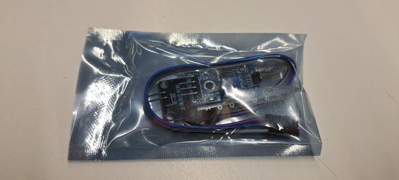
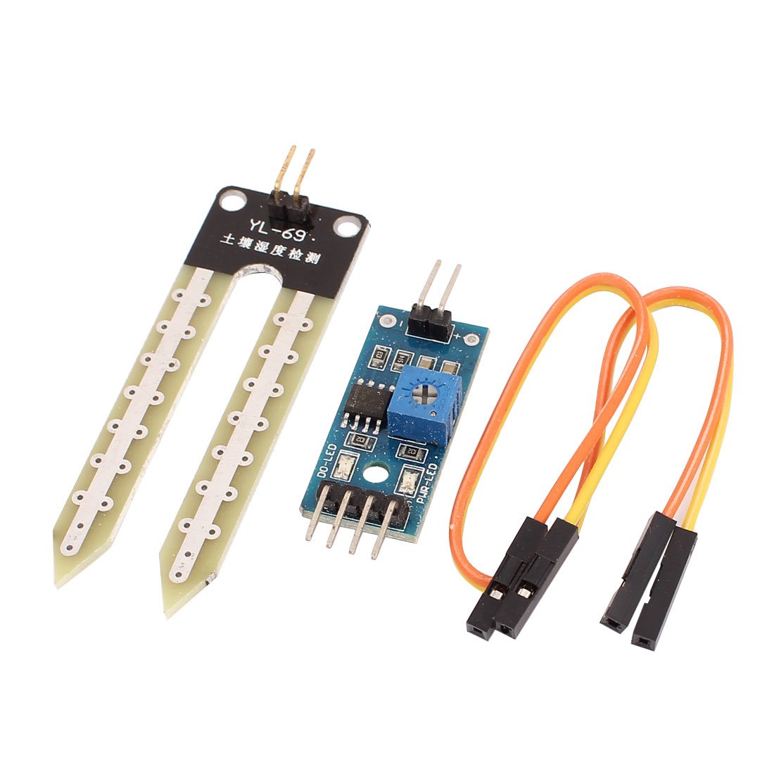
When there is water, the soil will conduct more electricity, which means that there will be less resistance. Dry soil conducts electricity poorly, so when there is less water, then the soil will conduct less electricity, which means that there will be more resistance.
This sensor can be connected in analog and digital modes. First, we will connect it in analog mode, and then digital.
Specifications
The specifications of the FC-28 soil moisture sensor are as follows:
- Input Voltage: 3.3–5V
- Output Voltage: 0–4.2V
- Input Current: 35mA
- Output Signal: both analog and digital
Pin-out
The FC-28 soil moisture sensor has four pins:
- VCC: Power
- A0: Analog Output
- D0: Digital Output
- GND: Ground

The module also contains a potentiometer, which will set the threshold value. This threshold value will be compared by the LM393 comparator. The output LED will light up and down according to this threshold value.
Test with the Soil Moisture Sensor
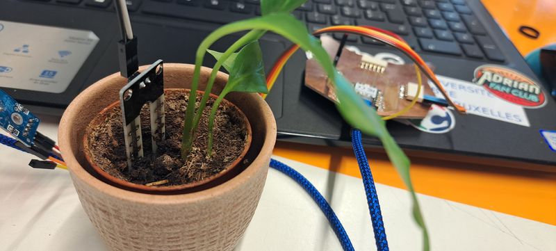
I failed this week in saving the different codes. When I started documenting my work I discovered that I saved all my Arduino files with the wrong name of sensor... So I had to play "puzzle" with the files and some are missing at the end, like this one. I will have to start again on this one to be able to share the code.
Will come soon...
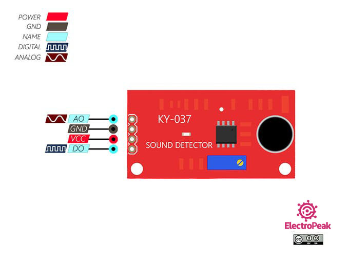
KY-037 Big Sound Sensor (infos from Electro Peak !)
KY-037 module consists of a capacitive microphone and an amplifier circuit. The output of this module is both analog and digital.
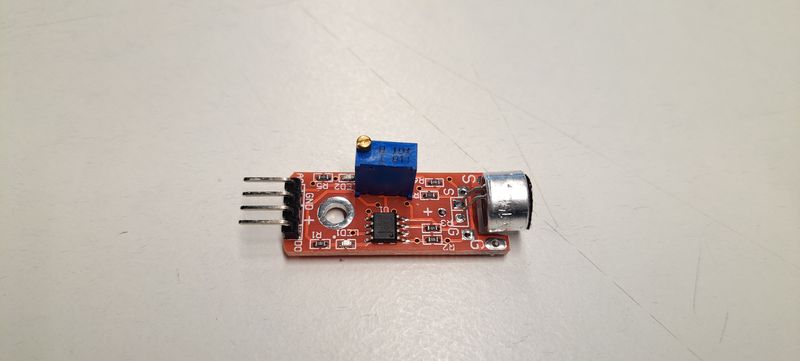
KY-037 Sound Module Pinout
This module has 4 pins, 2 of them are for power supply.
Pin 1: The analog output. It’s value changes according to the intensity of the received sound. It can be connected to the Arduino analog (ADC) pins.
Pin 4: The digital output. It acts as a key, and it activates when sound intensity has reached a certain threshold. The sensitivity threshold can be adjusted using the potentiometer on the sensor.
Test with the Big Sound Sensor
                          /*
                            modified on June 5, 2018
                            by Arduino Examples from arduino.cc/en/Tutorial/ReadAnalogVoltage
                            Home
                            */

                            void setup() {
                              // initialize serial communication at 9600 bits per second:

                              Serial.begin(9600);
                            }

                            // the loop routine runs over and over again forever:

                            void loop() {
                              // read the input on analog pin 0:

                              int sensorValue = analogRead(A0);

                              // print out the value you read:

                              Serial.println(sensorValue);

                              delay(50);
                            }
Hall Magnetic Sensor (infos from Techiescience)
The Hall Effect Sensor Arduino is a device that allows you to measure magnetic fields.
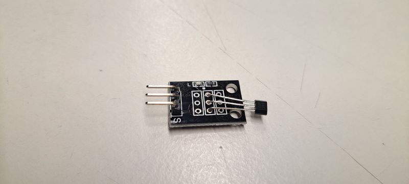
The sensor consists of a thin strip of semiconductor material, typically made of gallium arsenide or indium antimonide. This strip is placed in a magnetic field, and when a current flows through it, the Hall effect occurs.
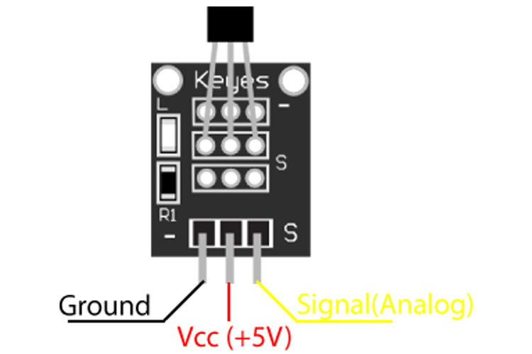
Pinouts
The module has 3 output points; Power, Ground, and Signal.
Applications
- Motor control
- Metal detector
- Position sensing
- Magnetic Code Reading
- Current sensing
Test with the Hall Magnetic Sensor
                          int Led = 26 ; // Led declaration on pin 26
                          int SENSOR = 4 ; // Sensor declaration on pin 4
                          int val ; // Variable number declaration

                          void setup (){

                            pinMode (Led, OUTPUT) ; // Define LED as output
                            pinMode (SENSOR, INPUT) ; // Define Sensor as input
                          }

                          void loop (){

                          val = digitalRead (SENSOR) ; // Reading sensor status

                            if (val == LOW) { // When sensor detects a magnet, LED 26 goes on

                            digitalWrite (Led, HIGH);
                            }

                            {
                            digitalWrite (Led, LOW);
                            }
                          }
Files and resources
My files
- Humidity and Temperature Arduino file
- Water Sensor Arduino file
- Big Sound Arduino file
- Hall Magnetic Arduino file
Resources