16. System Integration
Hero shot
Materials used
- 2x Laser cutted prototype box = ~10€
- 2x 5mm foggy round 4 pin RGB LED Light Emitting Diode - Common cathode = ~0.10€/LED → ~0.20€ total
- 1x HC-SR04 Ultrasonic Sonar Distance Sensor = ~2€
- 1x ESP32 Wroom = ~9€
- 1x AZ-Delivery Micro Servo Motor 9g compatible with SG90 = ~3€
- 1x Thin Flexible Force Sensitive Resistor - 20g to ~2kg = ~4€
- 1x Powerbank = ~20€
- Wires (~8) = ~0 05€/wire → ~1€ total
- 3D printed mounting brackets in PLA
- 3D printed ears in ABS
- Large brown paper tape
My project is a cat feeder with automatic opening/closing lid (triggered by a distance sensor) and LED light emitting diodes changing color regarding the quantity of food left in the bowl (thanks to a force sensitive resistor).
Therefor, several electronic components will be necessary and will require a clean wiring.
RGB LEDs
Two 5mm foggy round 4 pin RGB LED Light Emitting Diode (Common cathode) will be used on top of the feeder.
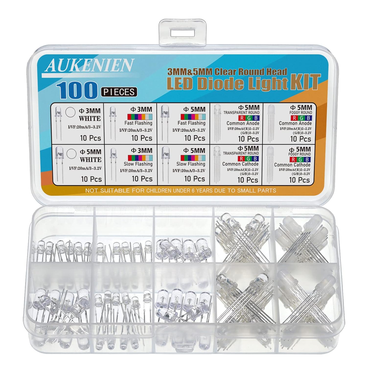
Each of them has 4 pins that will be connected to the ESP32 Wroom.
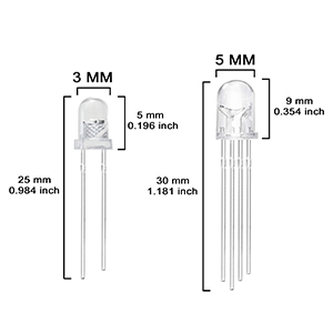
So 8 pins will be used on the ESP32, minus one as I will weld the 2 GND pins together (the ESP32 only has 3 GND pins).
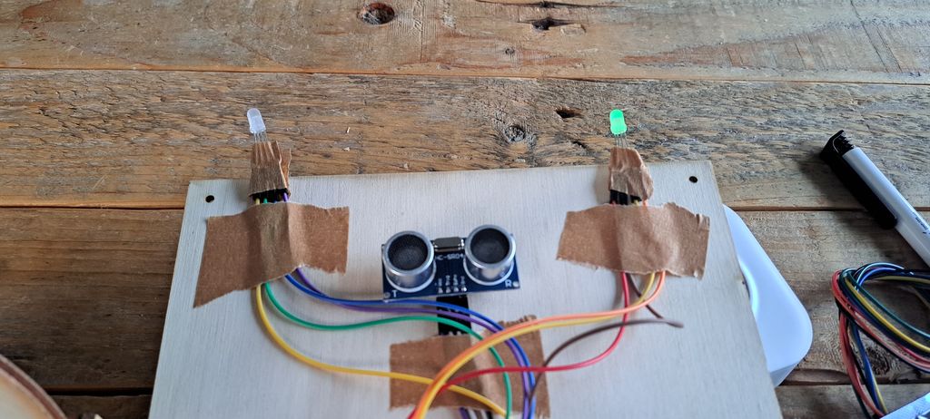
I thought about soldering both LEDs' similar pins together but someone (my lovely husband) reminded me that if one LED gets damaged, both will turn off. Not such a good idea then !
Distance Sensor
To get the bowl lid to automatically open and close, the first step is to detect an object (in this case a cat or it's human slave) at a determined distance of the feeder.
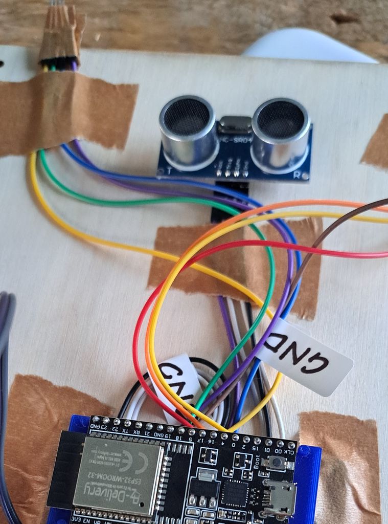
For that I will use an HC-SR04 Ultrasonic Sonar Distance Sensor which has 4 pins to attach to the ESP32.
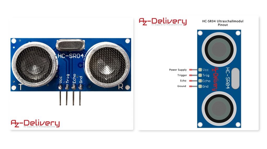
As I only used 1 GND pin for both LEDs, I will use another one for this component (I could weld it to the LEDs' GNDs' but I prefer moving baby steps as this is all new to me).
ESP32 Wroom
The main part in the electronic components is the microcontroller, in my case I will use a ESP32 Wroom.
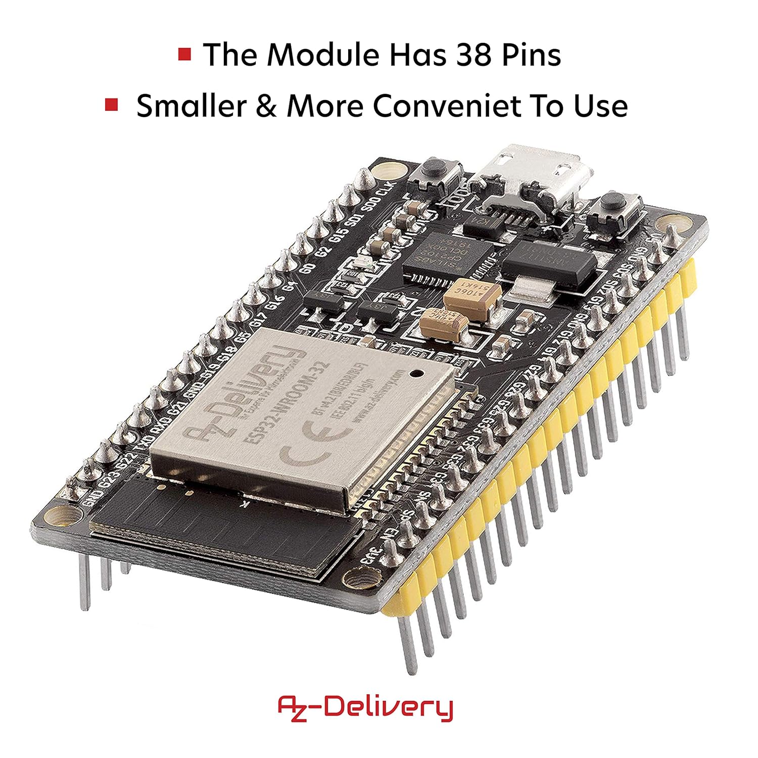
Why ?
Because I'm already thinking ahead and willing to trigger the lid opening/closing with a RFID chip and also allow the huma slave to get information on a smartphone app (in addition to the LED lights).
ESP32 NODEMCU Module WiFi Development Board with CP2102
Features
- As with the predecessor model ESP8266, the WLAN functionality is implemented directly in the SoC, but with additional Bluetooth function (incl. BLE).
- The ESP32 processor used combines a CPU with 2 Tensilica LX6 cores, clocked at up to 240 MHz, and 512 kiloBytes of SRAM in a single microcontroller chip.
- It also integrates a radio unit for WLAN (according to 802.11bgn) and Bluetooth (Classic and LE).
Specifications
| Item | Value |
|---|---|
| Power supply voltage (USB) | 5V |
| Input/output voltage | 3.3V |
| Required operating current | Min. 500mA |
| Soc | ESP32-Wroom 32 |
| Clock frequency range | 80MHz / 240MHz |
| RAM | 512kb |
| External flash memory | 4MB |
| I/o pins | 34 |
| Interfaces | SPI, I2C, I2S, Can, Uart |
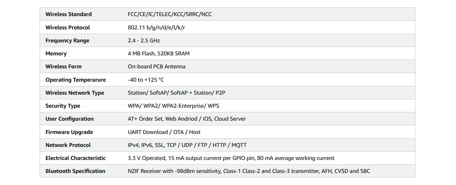
| Wi-fi protocols | 802.11 b/g/n (802.11n up to 150 Mbps) |
| Wi-fi frequency | 2.4 GHz - 2.5 GHz |
| Bluetooth | V4.2 - BLE and Classic Bluetooth |
| Wireless antenna | PCB |
| Dimensions | 56x28x13mm |
To hold the ESP32 in place and get enough space under it for the wires that will be attached to it I added a PLA 3D printed bracket (file was found on Thingiverse, thanks to...).
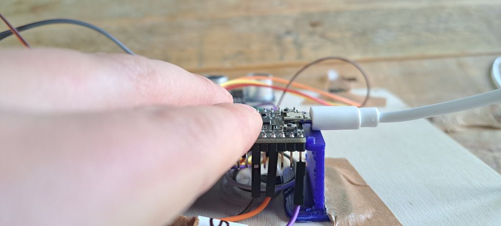
I will add some double-face tape for this prototype and upgrade it on the next one.
Servo motor
In order to lift the lid of the bowl I will use a Micro Servo Motor 9g compatible with SG90.
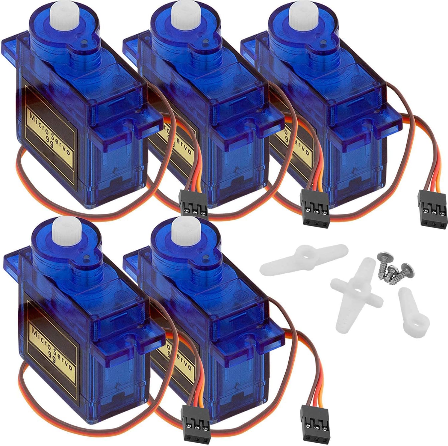
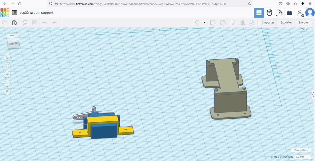
It will be fixed to the inner back part of the bowl compartment with the help of another 3D printed bracket found this time on Tinkercad.
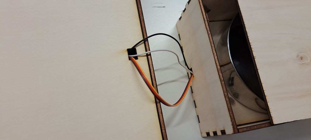
The servo motor has 3 pins to attach to the microcontroller. Therefor I've cut a small hole in both the cat head tower front plate and the back plate of the bowl compartment.
Force resistor
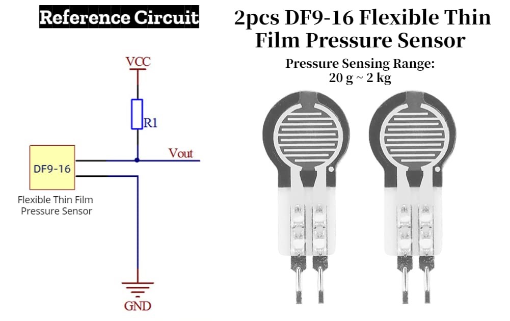
Final component to add to the feeder is the Thin Flexible Force Sensitive Resistor that can measure weights going from 20g to 2kg.
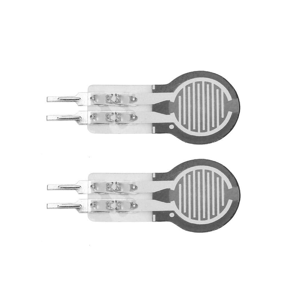
This one has 2 pins but one gets split in 2 : VCC (+ resistor) and Vout.
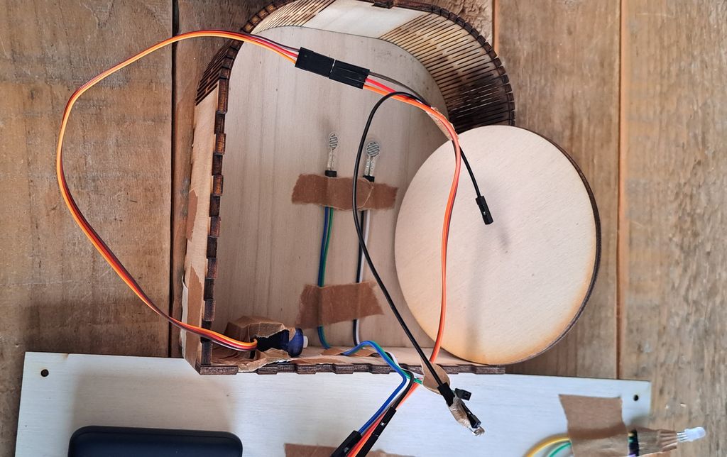
I haven't tried it out yet so I don't know if I will need 1 or 2 and how to fix them to get the right measurements.
I first thought I should use both so I placed them and calculated all the wires together.
A few days later I've been thinking about how to hide it under the bowl and only used one when I cut the wood piece.
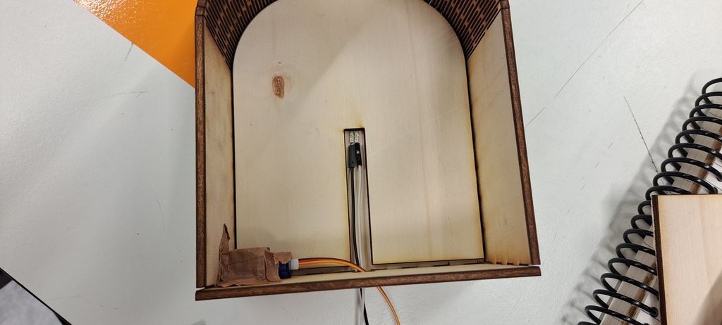
We'll see at the end what will work the best and if this wood piece will be enough.
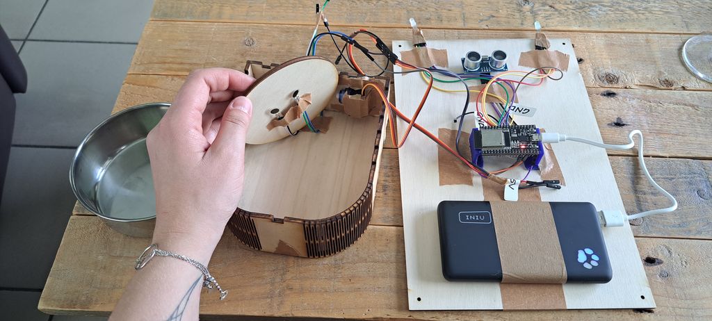
Current state
This is how the integration looks like for the moment. :)

Files and resources
Files
Resources