Electronics Production
group assignment:
-[X]characterize the design rules for your in-house PCB production process -[]send a PCB out to a board house
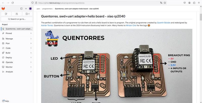
Our assignement was to build a microcontroller development “Quentorres” board and make it work by programming the blinking of a LED light
We did several tests to choose the right material and tips.
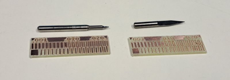
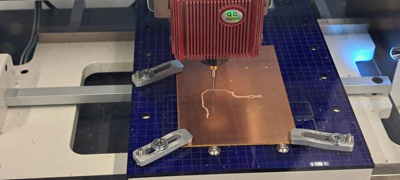
Tip test
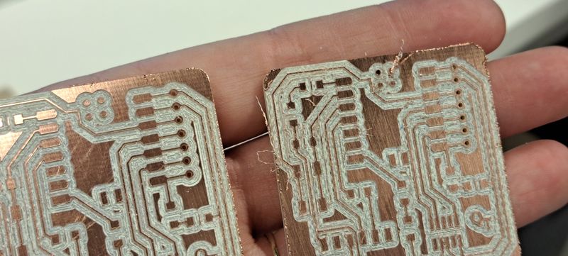
We launched a small PCB model on the CNC and used 2 types of tips : a “V” one and an “helocoidal” one.
As you can see below, the helicoidal tip is giving a much better and precise result than the “V” one.
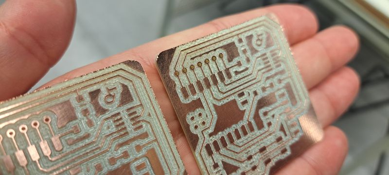
Material test
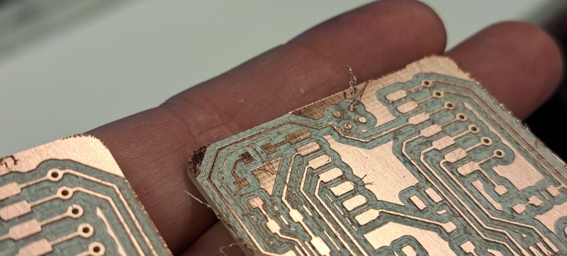
We also tried out the Quentorres board on 2 different materials : FR1 (phenolic paper) and FR4 (epoxy glass).
The Epoxy Glass (first picture below) gives a much better result, that’s why we used it to complete this assignment.
Preparing the G-Code files
To get the Quentorres board cut and engraved, we had to prepare the G-Code files that will run the CNC to get the physical base of the board (without its components).
We prepared the G-Code files in Mods .
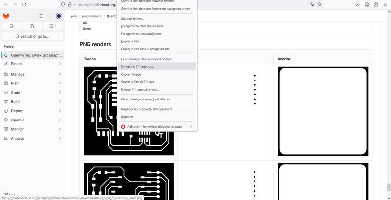
For that, we saved the Quentorres PNG files that are in the Fabcloud (no need to rename the files).
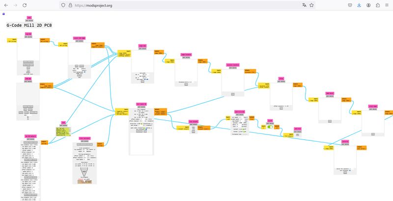
Discovering Mods
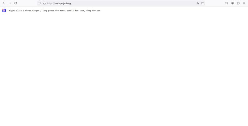
The Mods website is simple to use and has a minimalist interface.
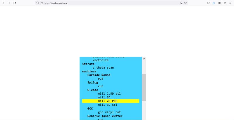
To create the G-Code files, you have to right-click on the interface and choose “G-Code > mill 2D PCB”. This will open all the parameters you’ll need to configure the Quentorres PCB cutting and engraving.
First we worked on the “traces” file by opening it in the “read png” box.
To create the traces, we had to insert the path parameters in the “path to G-code” box.
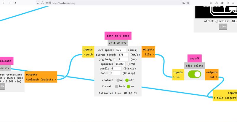
- cut speed : 175
- plunge speed : 175
- jog height : 2
- spindle : 11000
- dwell : 0
- tool : 0
- coolant : off
- format : mm
Then we changed the mill raster parameters in the “mill raster 2D” box.
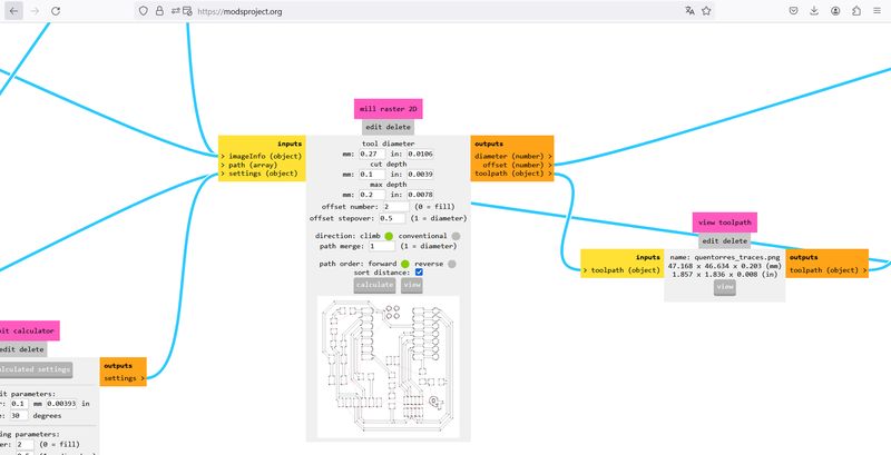
- tool diameter : 0.27mm
- cut depth : 0.1mm
- max depth : 0.2mm
- offset number : 2
- offset stepover : 0.5
- direction : climb
- path merge : 1
- path order : forward
- sort distance : checked
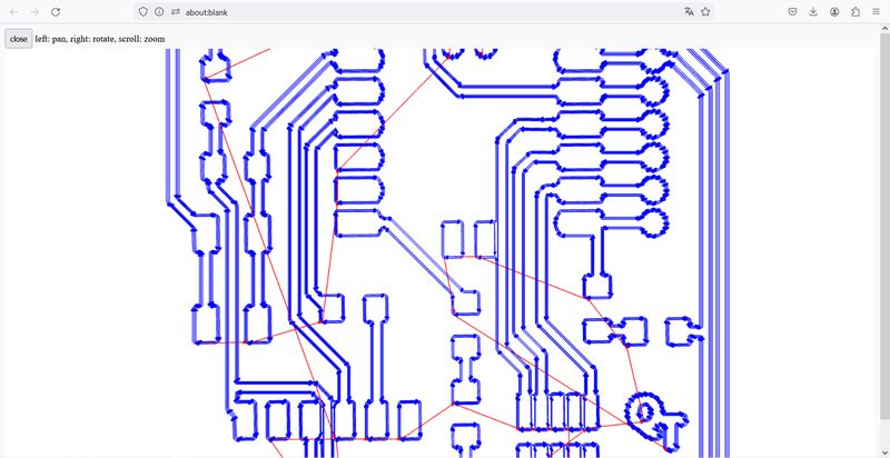
After entering all the parameters, clicking on “Calculate” (in the bottom of the “mill raster 2D” box) will generate the G-Code file and open a view of the result. This shows where the tool will engrave.
After the “traces” file, we did the same for the “drill” file and changed the path parameters by :
- cut speed : 175
- plunge speed : 175
- jog height : 2
- spindle : 11000
- dwell : 0
- tool : 0
- coolant : off
- format : mm
And the mill raster 2D parameters by :
- tool diameter : 0.8mm
- cut depth : 1mm
- max depth : 1.35mm
- offset number : 1
- offset stepover : 0.5
- direction : climb
- path merge : 1
- path order : forward
- sort distance : checked
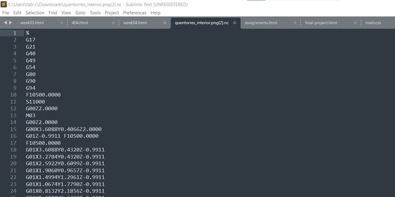
Here’s how a G-Code looks like when you open it in a simple text computer program :
Last but not least, we opened the “interior” file and also changed the parameters.
Here are the path parameters :
- cut speed : 175
- plunge speed : 175
- jog height : 2
- spindle : 11000
- dwell : 0
- tool : 0
- coolant : off
- format : mm
And the mill raster 2D parameters :
- tool diameter : 1mm
- cut depth : 1mm
- max depth : 1.35mm
- offset number : 1
- offset stepover : 0.5
- direction : climb
- path merge : 1
- path order : forward
- sort distance : checked
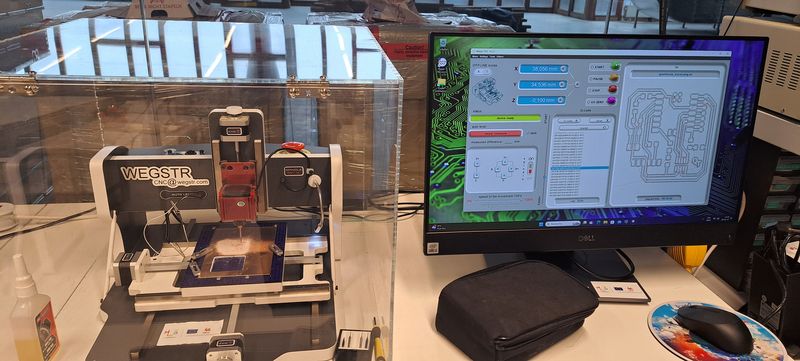
Engraving, drilling and cutting the board with the CNC
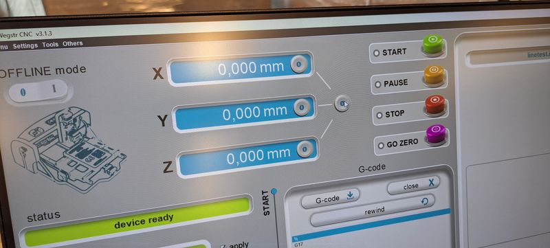
The CNC we have for PCB boards is a Wegstr.
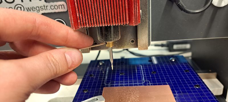
To get the finished Quentorres board, we have to start by the engraving part.
First we had to change the tip and insert a 0.27mm helicoidal one .
Then to open the G-Code file on the Wegstr computer program.
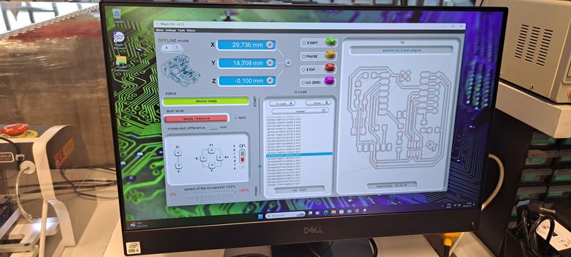
We had to configure the “zero” level on the Z-axis of the machine by connecting a little cable and move the Z-axis until the light goes on.
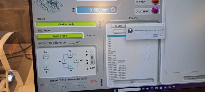
After that, we checked the level every 5 mm on the plate by using the “auto-level” option so that the machine remembers where the levels change a bit and will adjust by itself during the engraving process.
When we were sure that every basic parameter was ok, we launched the machine.
Next step was the drill part of the board. We had to change the tip to a 0.8mm one and calculate again the “zero” level of the Z-axis. We could then launch the machine.
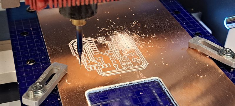
Last step, the cutting of the board with the 1mm helicoidal tip.
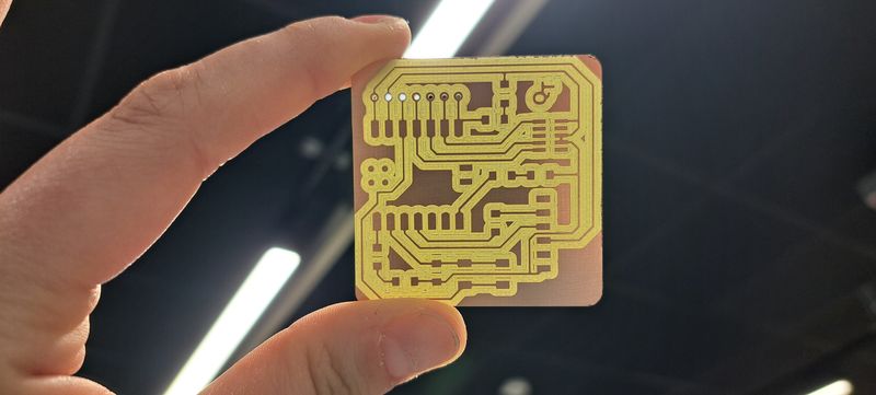
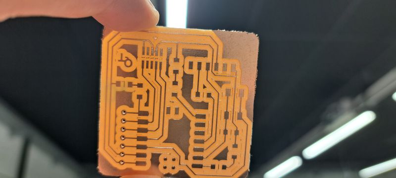
The result looks pretty good but the boards will need to be cleaned to get all the little copper pieces off.
Here’s the final result after cleaning.