Weekly assignments
- week 1. Project Management
- week 2. Computer Aided Design
- week 3. Computer Controlled Cutting
- week 4. Electronics Production
- week 5. 3D Scanning and Printing
- week 6. Embeded Programming
- week 7. Computer Controlled Machining
- week 8. Electronics Design
- week 9. Output Devices
- week 10. Mechanical design & Machine Design
- week 11. Break & Midterm Review
- week 12. Input devices
- week 13. Moulding and Casting
- week 14. Networking and communications
- week 15. Interface and application programming
- week 16. Wildcard week
- week 17. Applications And implications
- week 18. Project Development
- week 19. Invention, Intellectual Property and Income
Week5. 3D Scanning and printing
Group assignment:
Test the design rules for your 3D printer(s)
Individual assignment:
1. 3D Design Introduction
3D printing is a rapid prototyping technology. It is based on digital model files and uses bondable materials such as powdered metals or plastics to construct objects layer by layer.
3D printing technology has been widely applied in many fields like manufacturing, healthcare, aerospace, art design, etc. It enables the production of complex shapes, reduces material waste, shortens the product development cycle, and provides possibilities for personalized customization.
Common 3D Design Softwares:
- Fusion360:
Fusion 360 is a highly versatile 3D printing software that offers a seamless integration of design, simulation, and manufacturing capabilities. It provides advanced tools for parametric modeling, allowing users to make precise and customizable designs. The software also supports collaborative work, enabling teams to work together on projects efficiently.
- SolidWorks:
SolidWorks is renowned for its robust and accurate modeling features, especially in mechanical engineering. It offers a wide range of tools for creating complex mechanical parts and assemblies. SolidWorks has extensive libraries of standard components, which saves time in the design process.
- Blender:
Blender not only excels in 3D modeling but also stands out in animation and rendering. It provides a flexible and intuitive interface for both beginners and experienced users. With its powerful modifiers and simulation capabilities, Blender allows for the creation of dynamic and visually stunning 3D scenes.
- Autodesk Maya:
Autodesk Maya is a professional-grade software widely used in the entertainment industry. It offers sophisticated tools for character modeling, animation, and visual effects. Maya's node-based workflow gives artists a high degree of control over the creative process, resulting in highly detailed and realistic 3D models and animations.
2. 3D Design Using Fusion360
I will mainly introduce the process of how I designed the 3D part of my Final Project, the sword handler parts.
Step1 Decide the Components
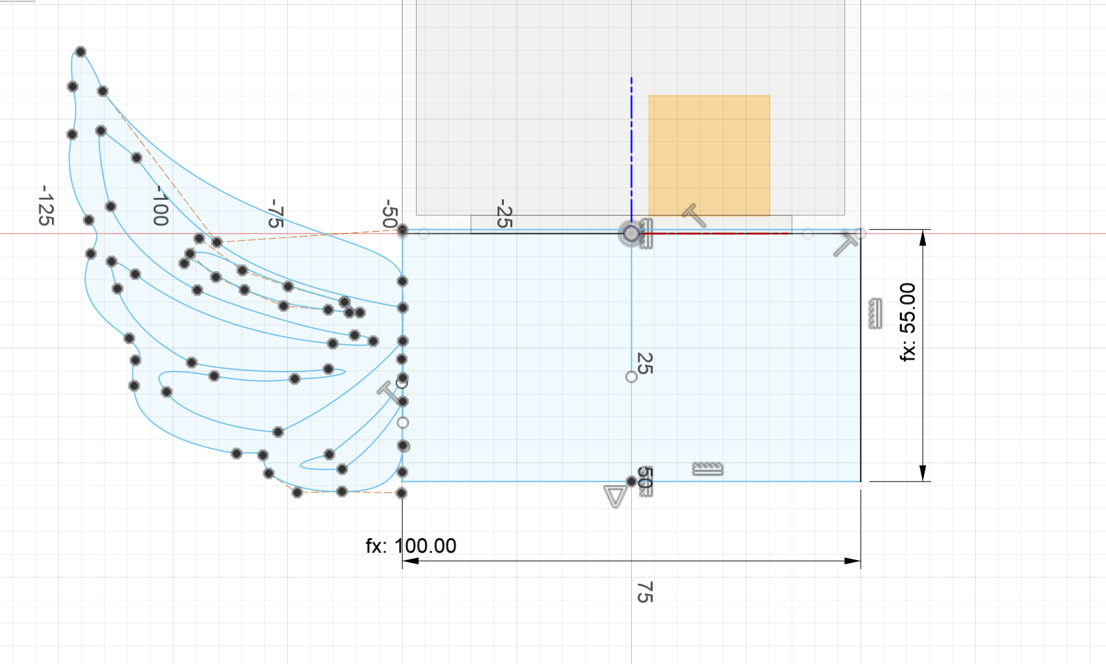
It is always very important to decide your components design first.My sword box part will be divided to two components, one is the outer shell of the box and the other are the wing aside the box.
Step2 Design the Box Part
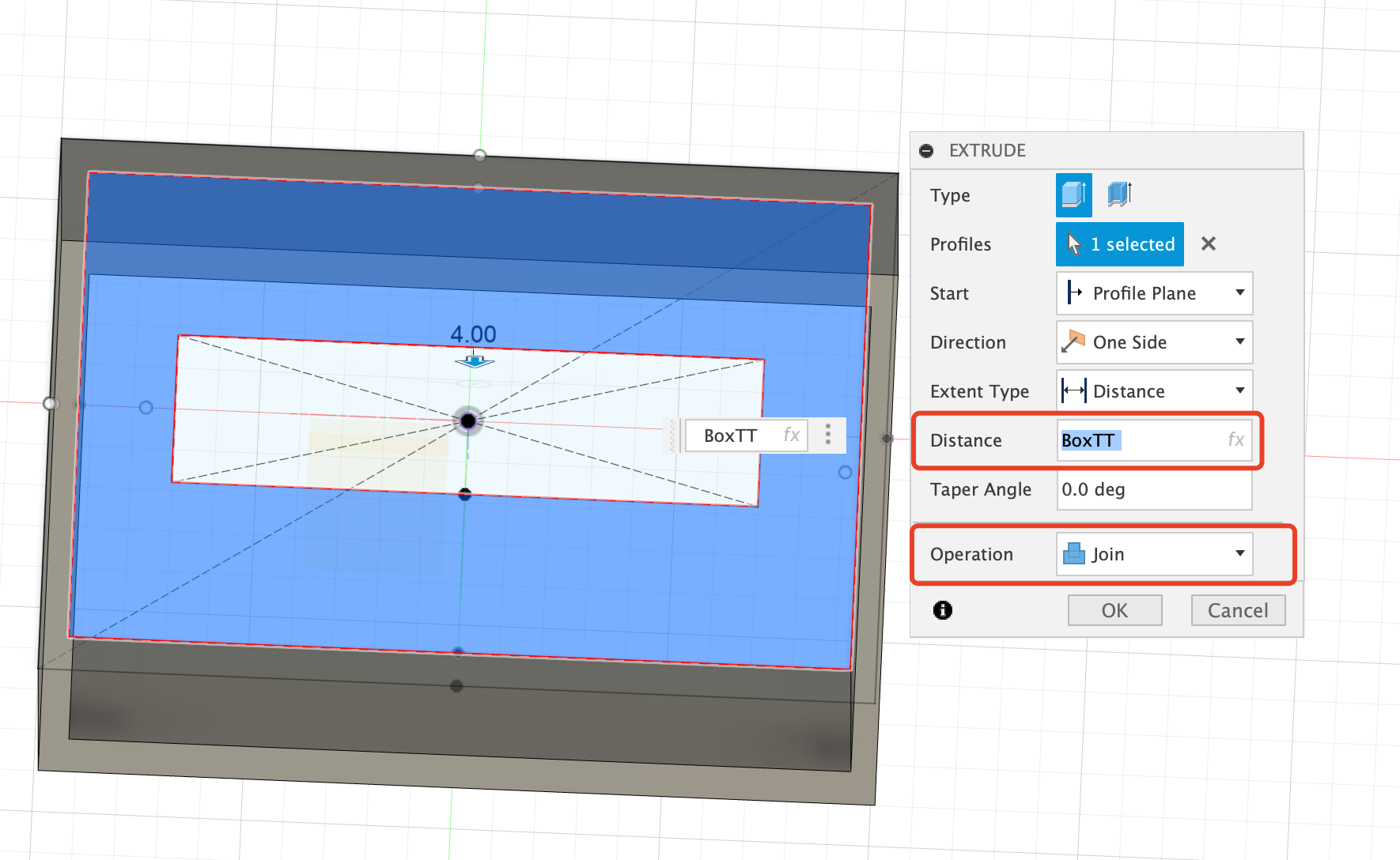
The box part is relatively easy, the main points are:
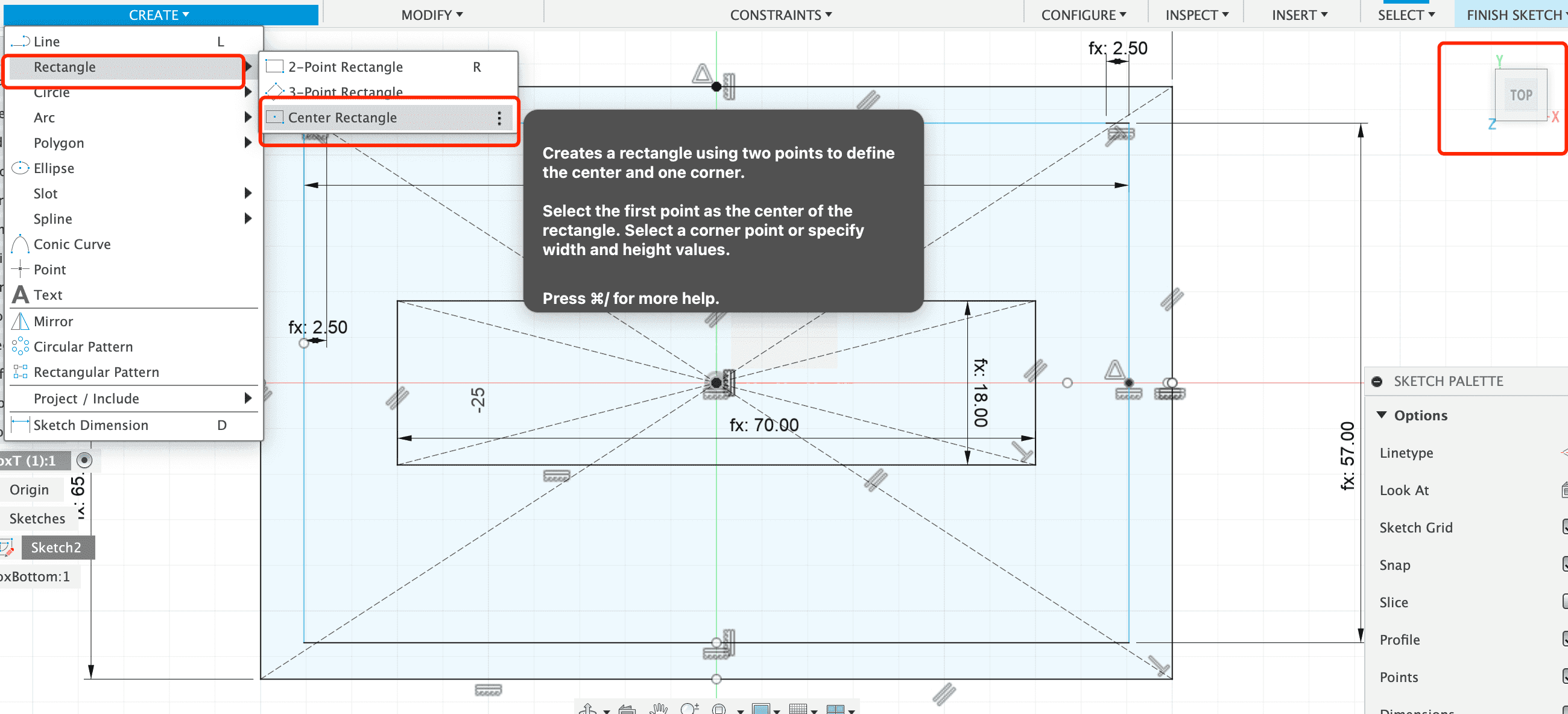
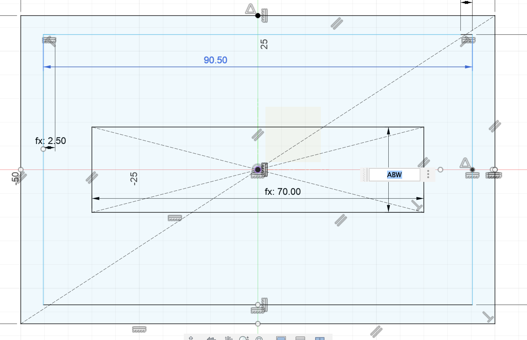
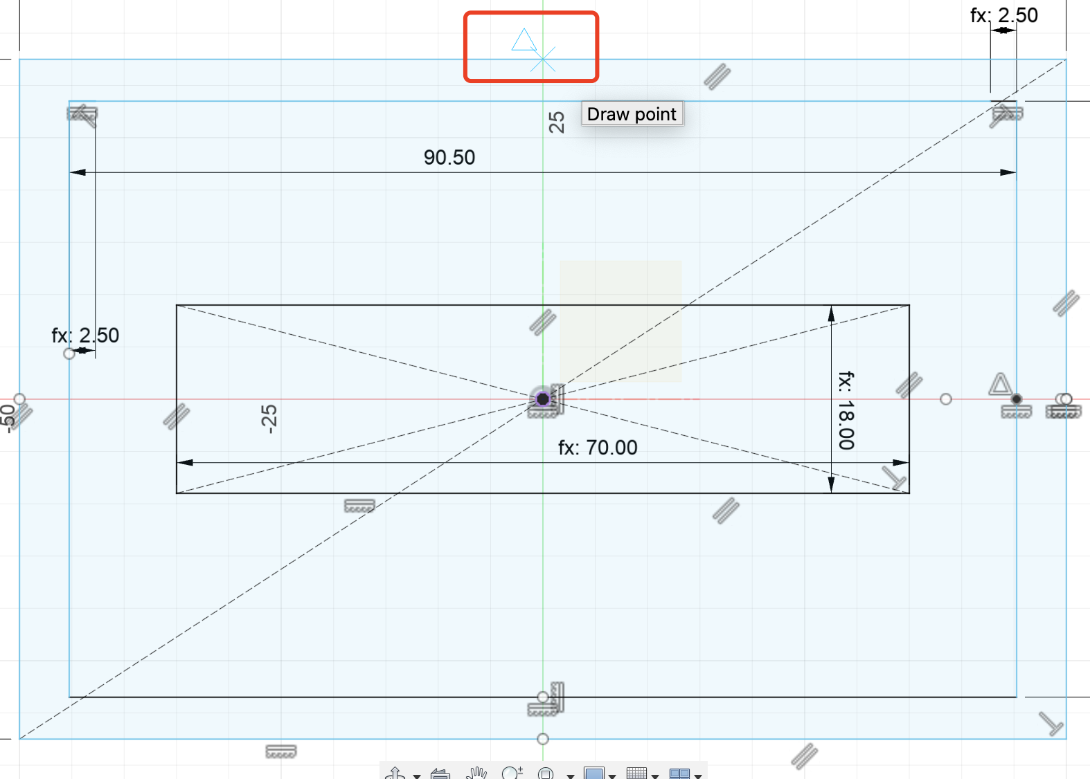
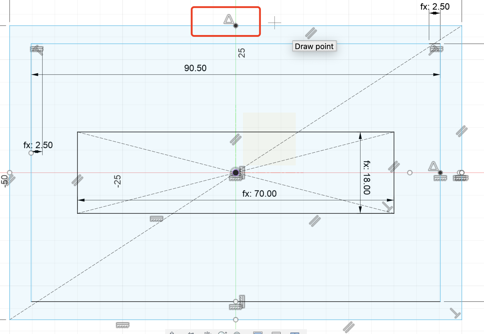
- Create the sketch on the top plane.
- Use the origin in the coordinate system as the center point of the subsequent rectangular box.
- Align all the middle point of the line of the rectangular to the origin point to make it more reliable.
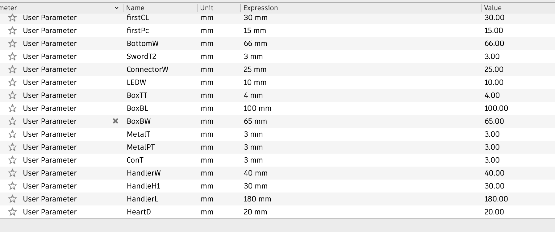
- All the height or length should use parameter settings in case of changing the box size later.
- Extrude different part based on their real value needed, like the box top only need to extrude to the thickness of the whole box.
 < p> 2. Set the length and width data all based on parameters
 < p> 3. Find the middle point of each line and align it with the origin point.
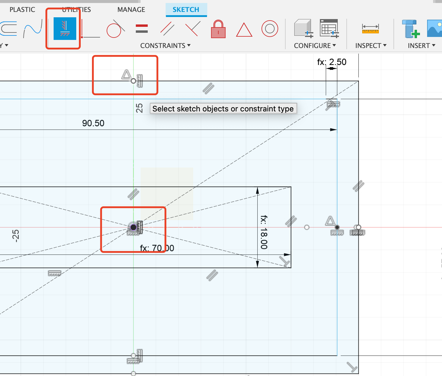
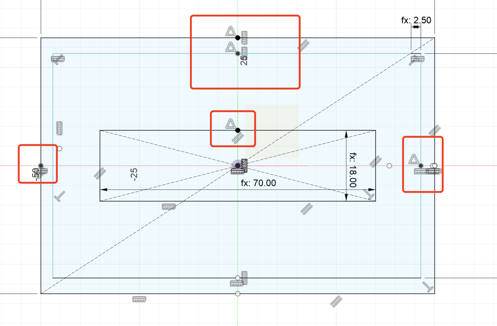
4. Extrude based on diffrent parameter.
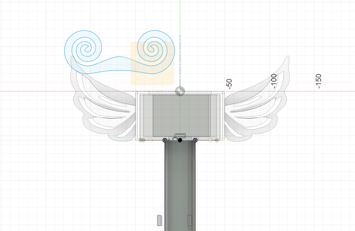
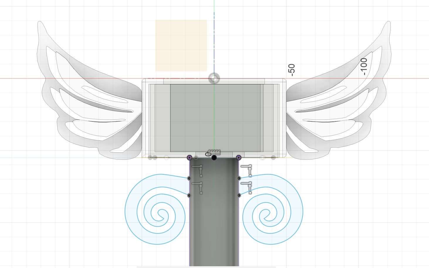
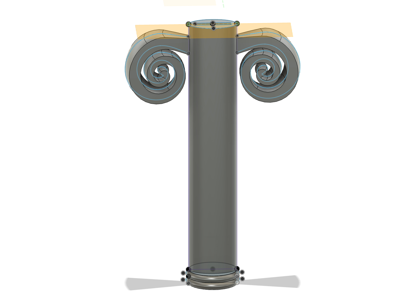
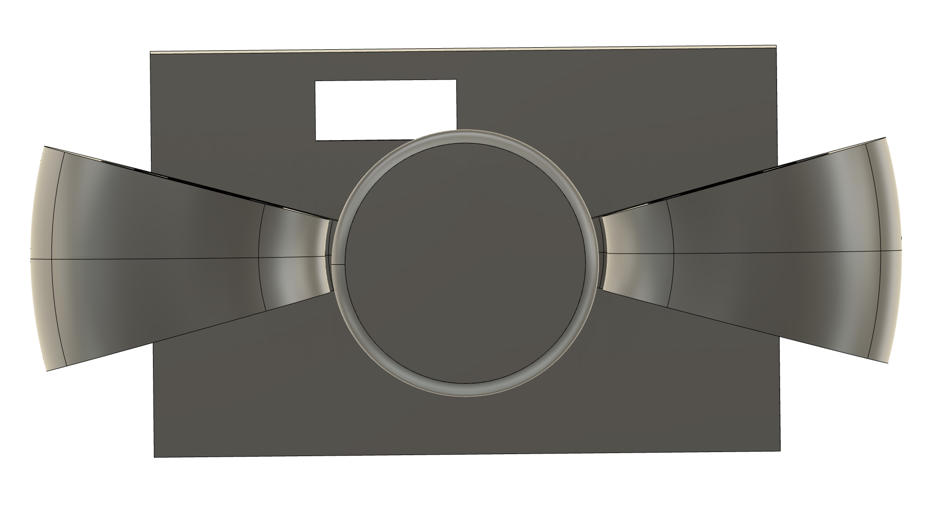
Step3 Design the Wing Part
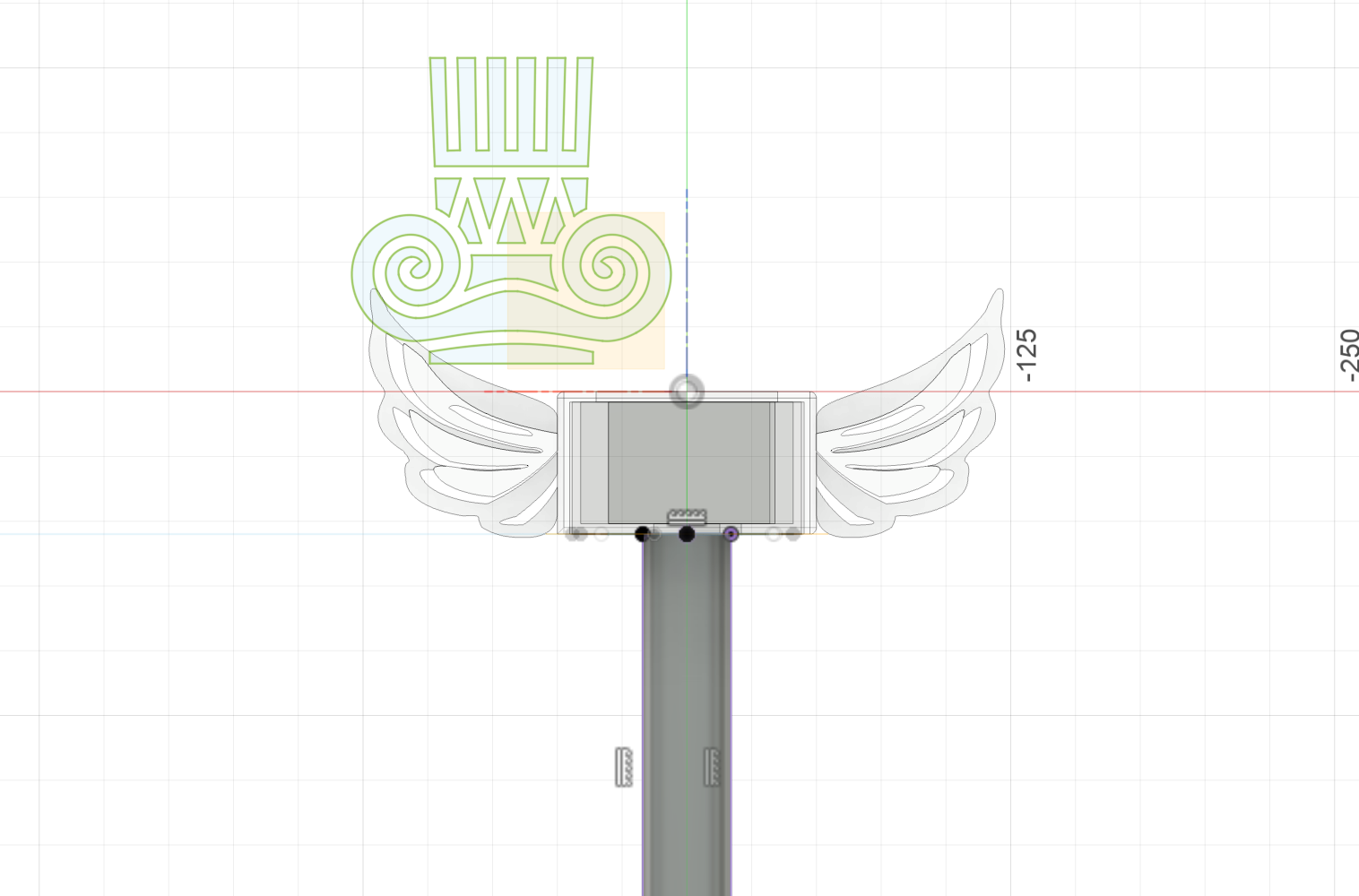
- First I designed the wing to be on the plane that is half of the box.
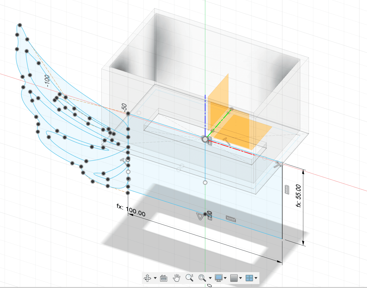
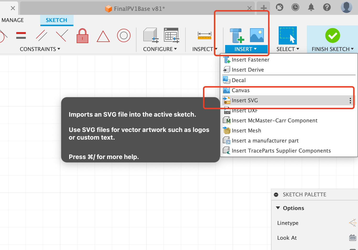
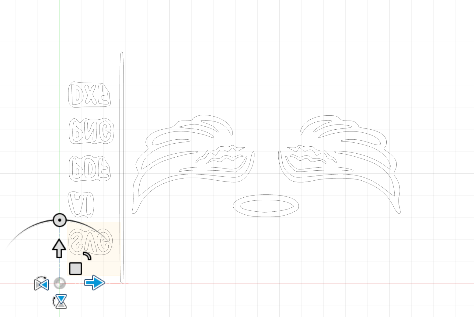
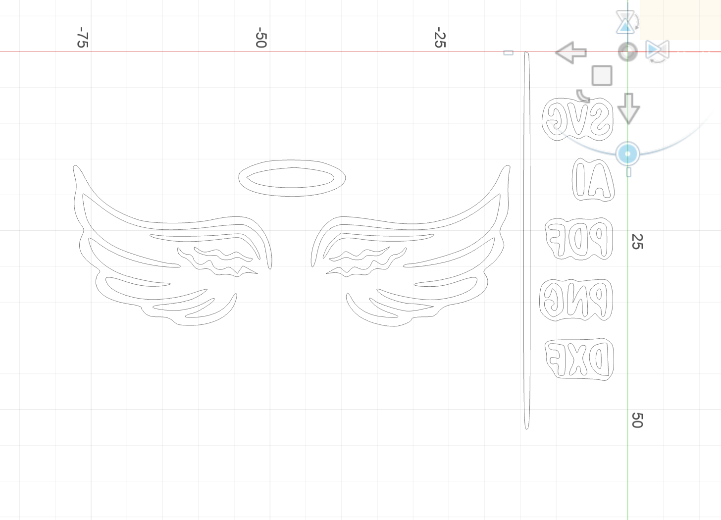
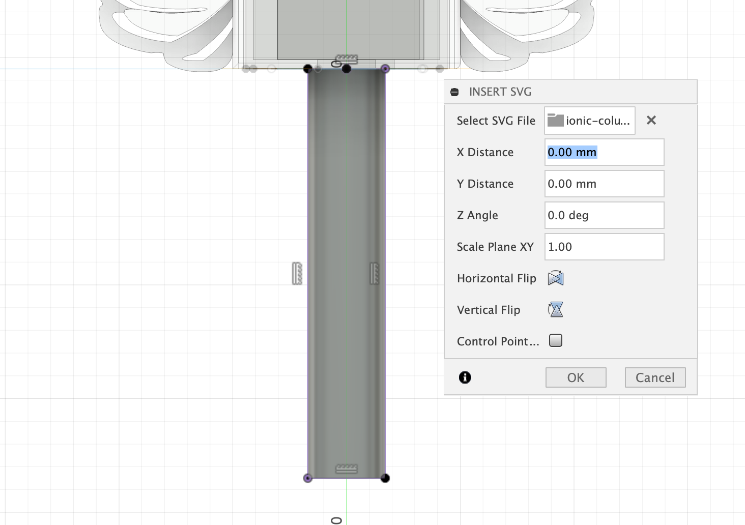
- For the wing part, I used the fusion's function that you can create a sketch from a svg file.

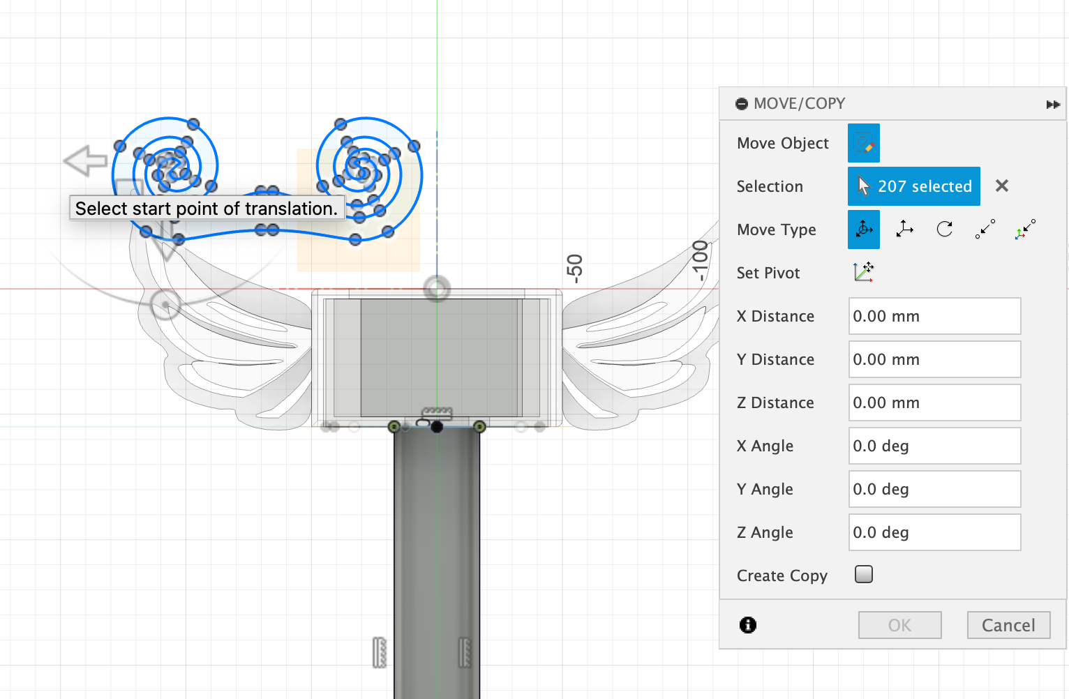
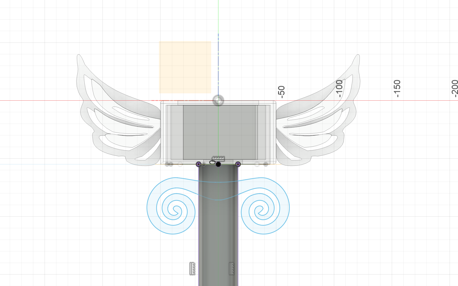
- Rotate it 180 degrees
- Remove the part unwanted
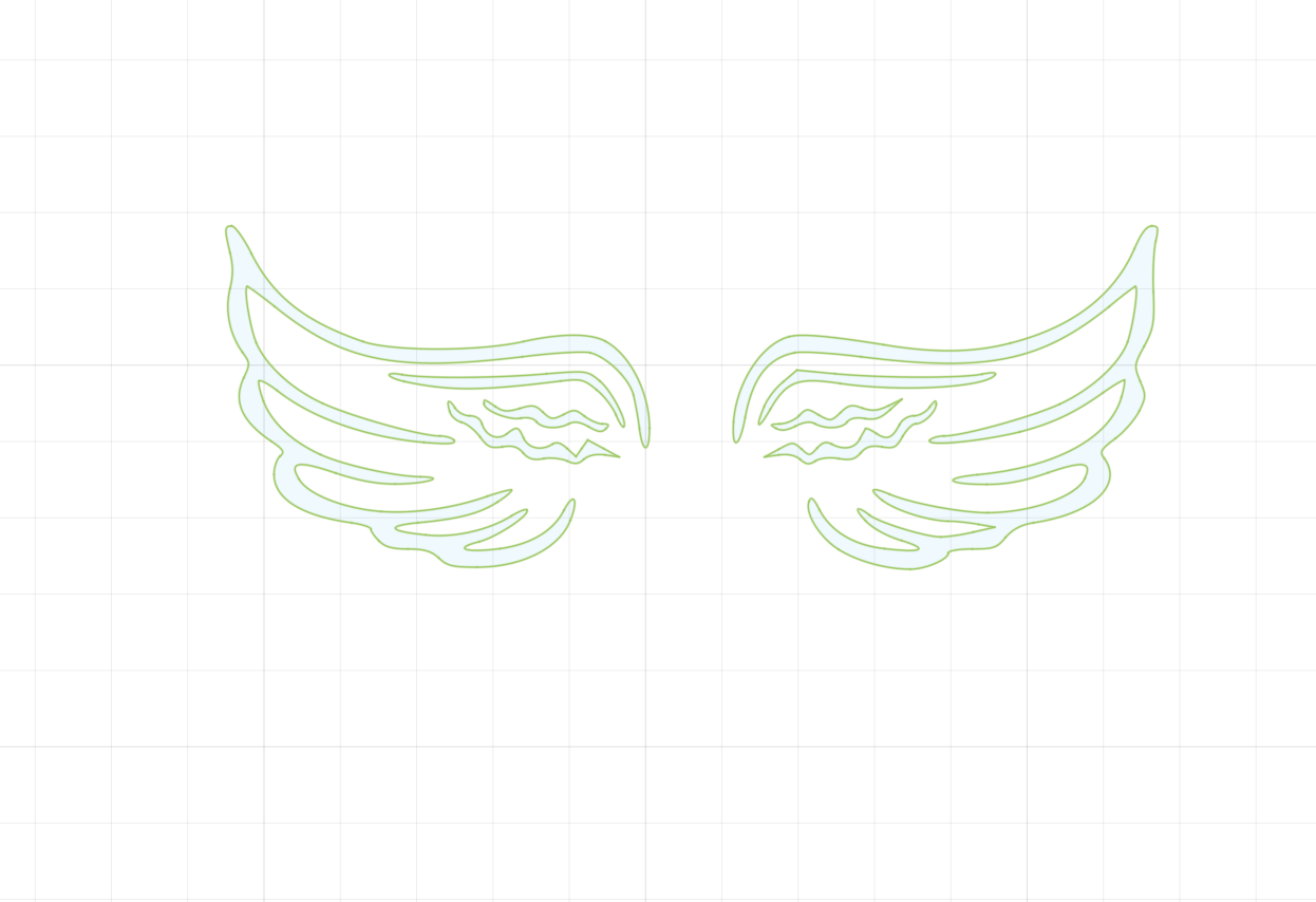
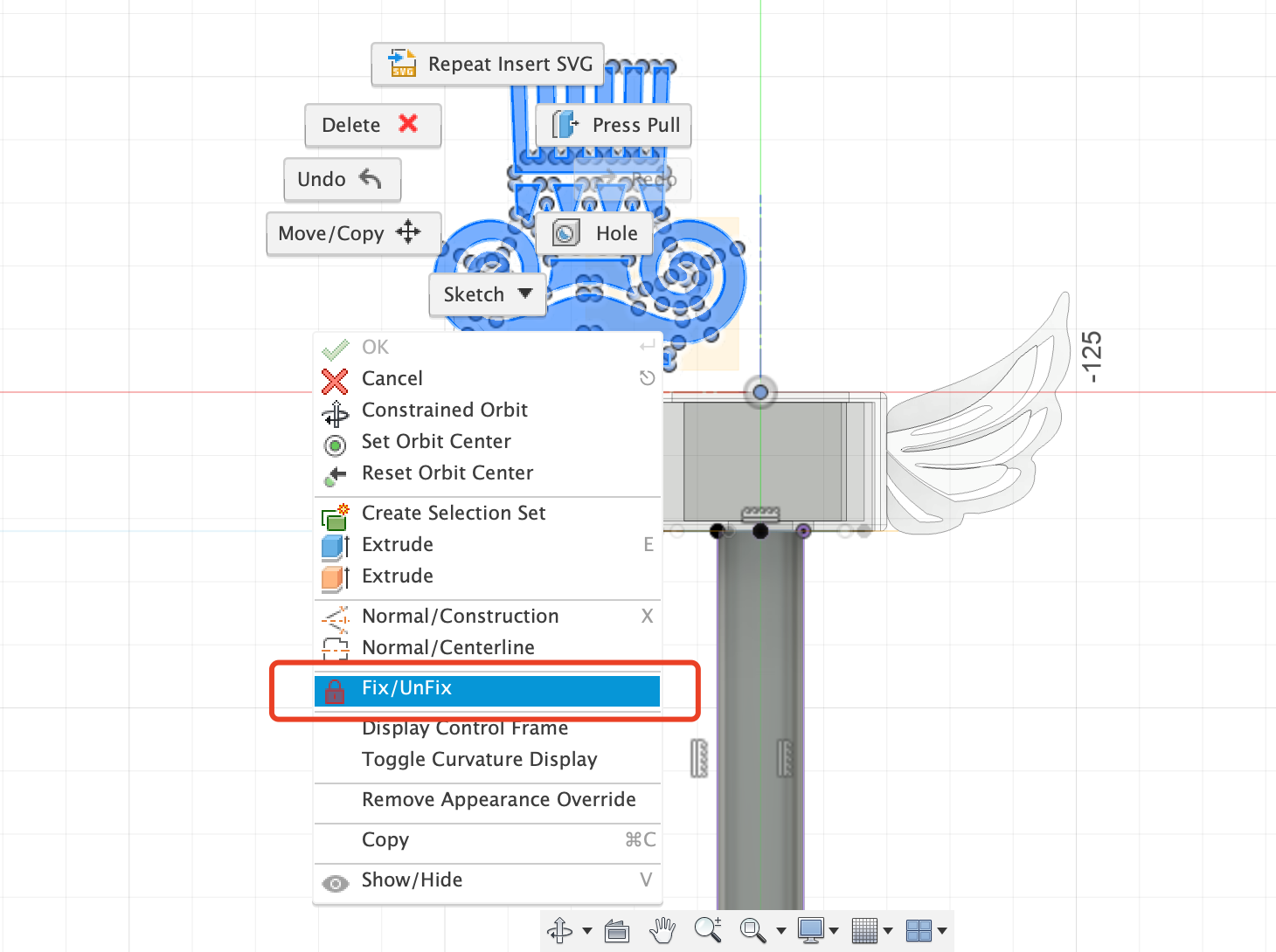
- Important! Unfix operation is needed to have access to edit the sketch.
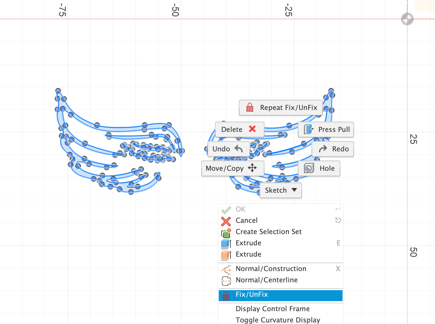
- Then I created a rectangle, retained half of the wing and removed unrelevant lines.
- When I wanted to extrude this wing, I found that it was actually divided into two parts. Then I could locally scale these two parts and extrude them respectively to form a hollow effect.
- Extrude the inner part to be the same thickness as the box, and the outter part to be half of the thickness of the box
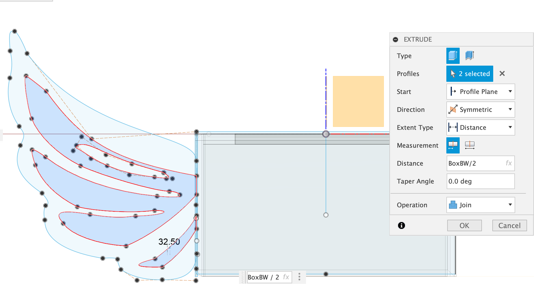
- Scale the inner part to be smaller,go to Modify->Scale
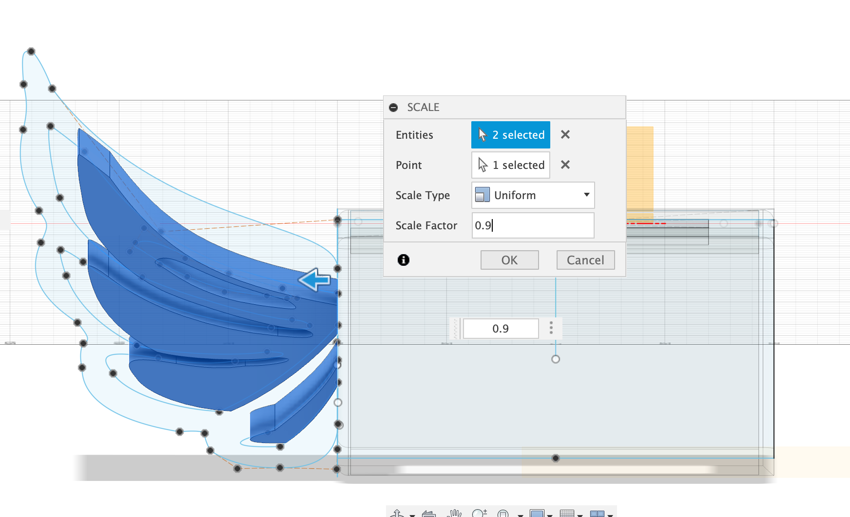
- Extrude the outter part to be half of the thickness of the box
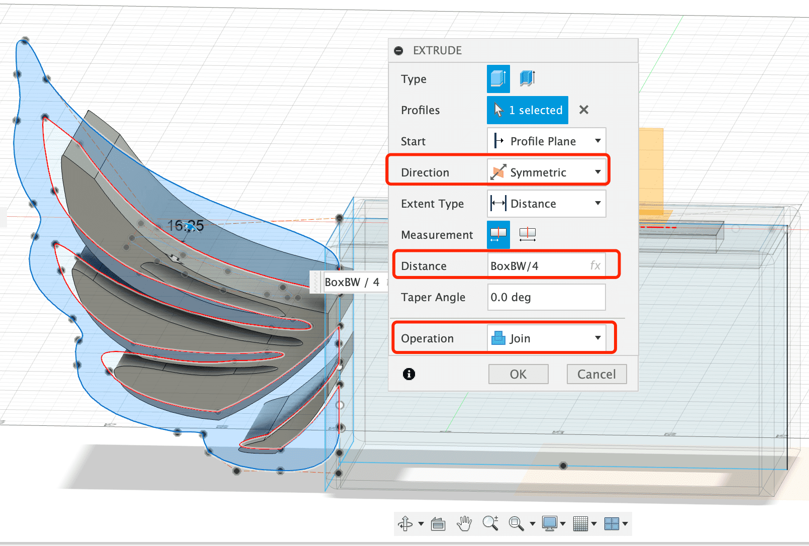
- Hollow effect is done!
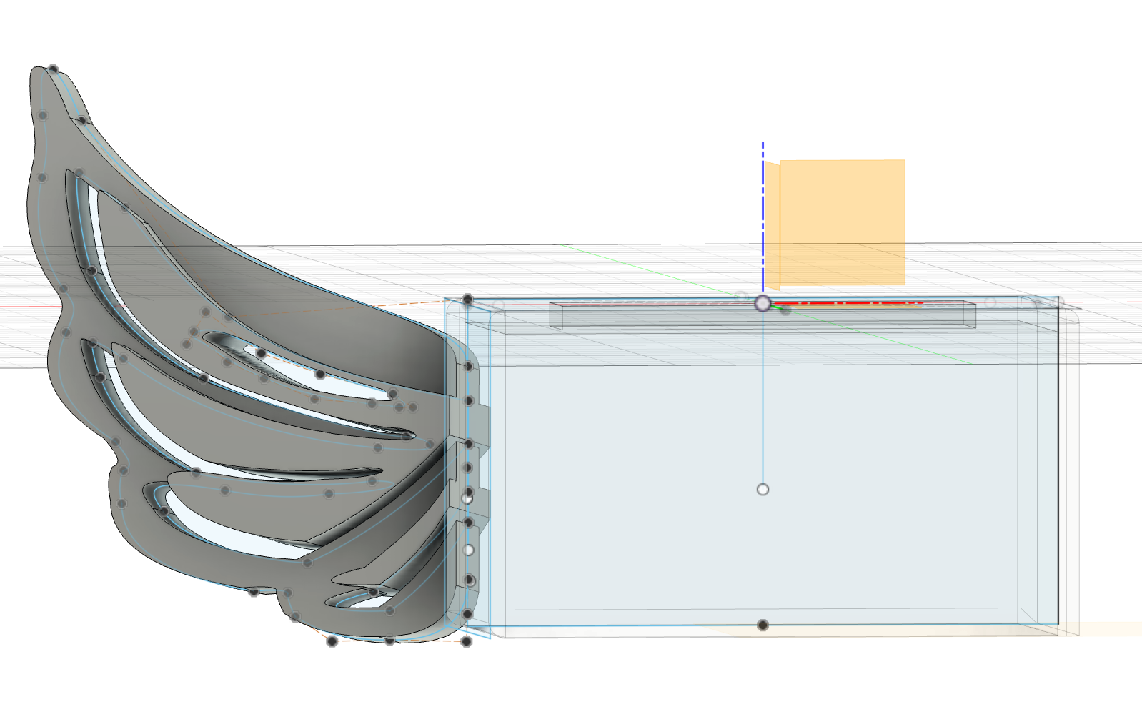
- Mirror the wing based on the middle plane
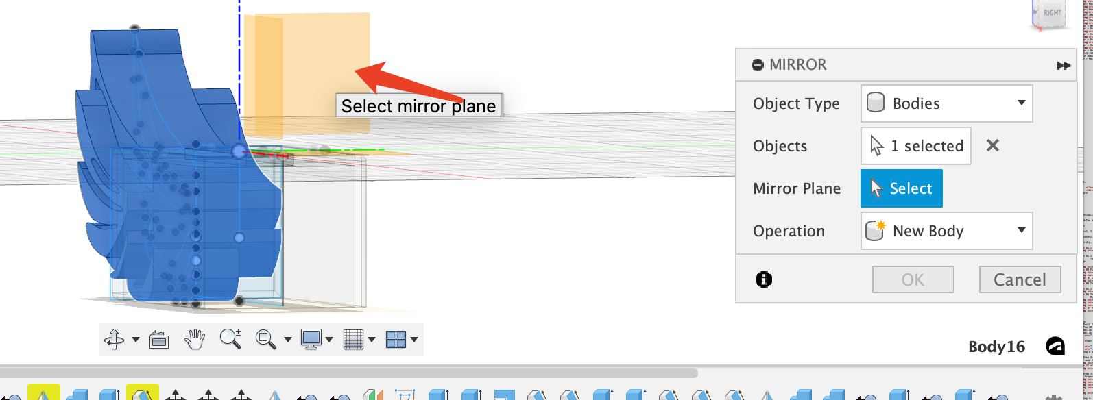
- Mirrored Wings with Box is done!
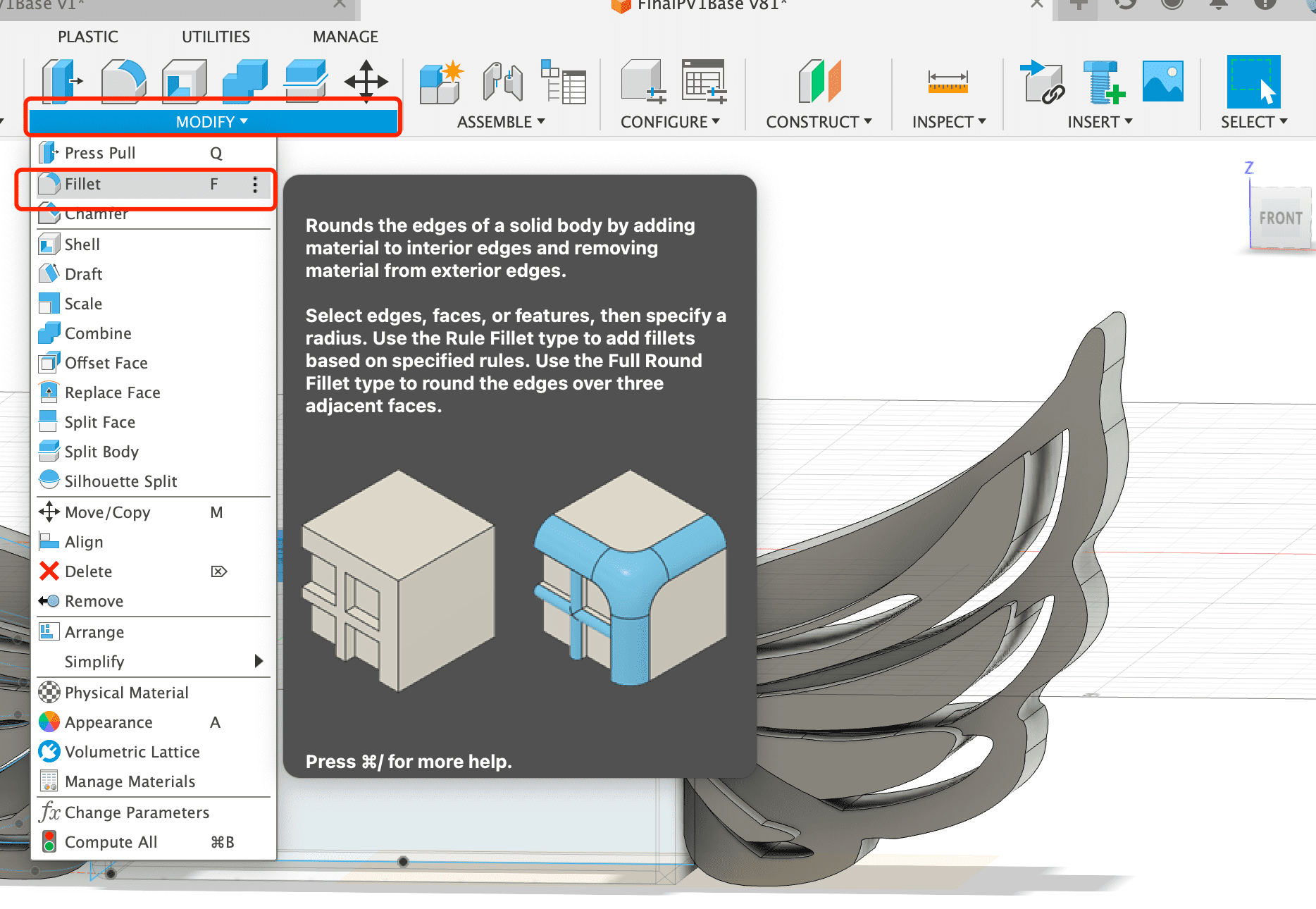
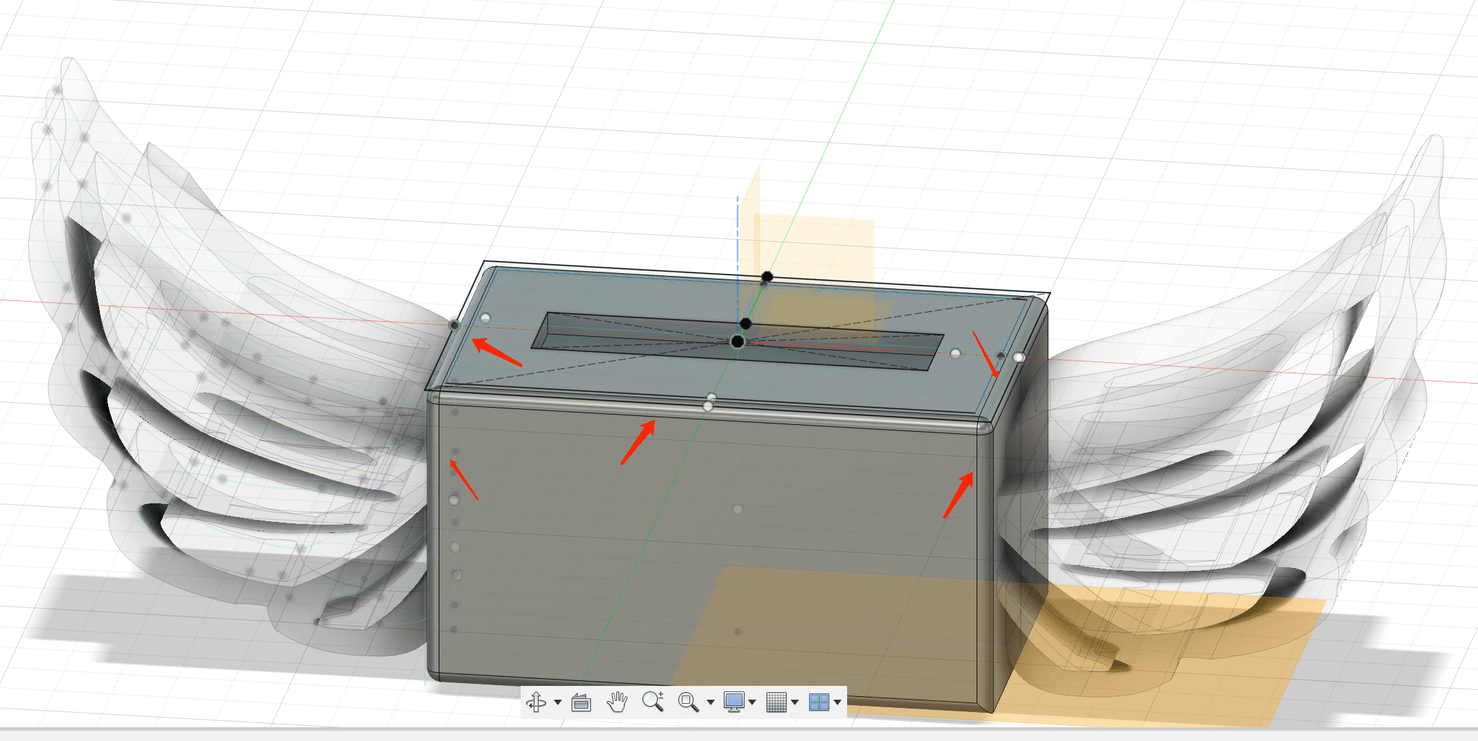
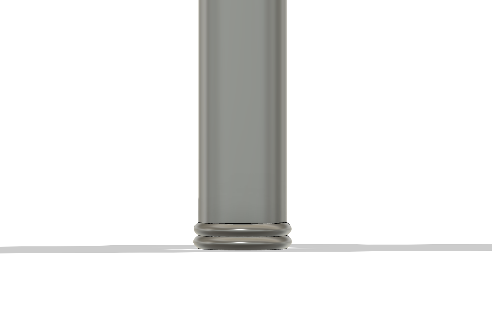
Step4 Fillet the Box
Fiilet the box so it can be more smooth,choose multiple edges to fillet, untill all boarders are smooth

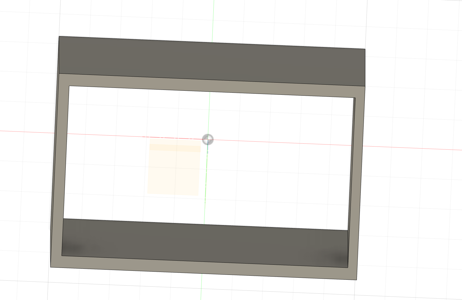
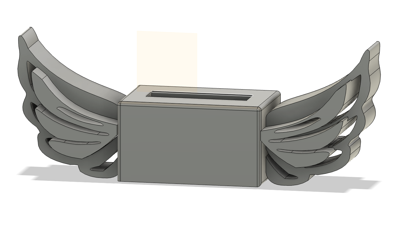
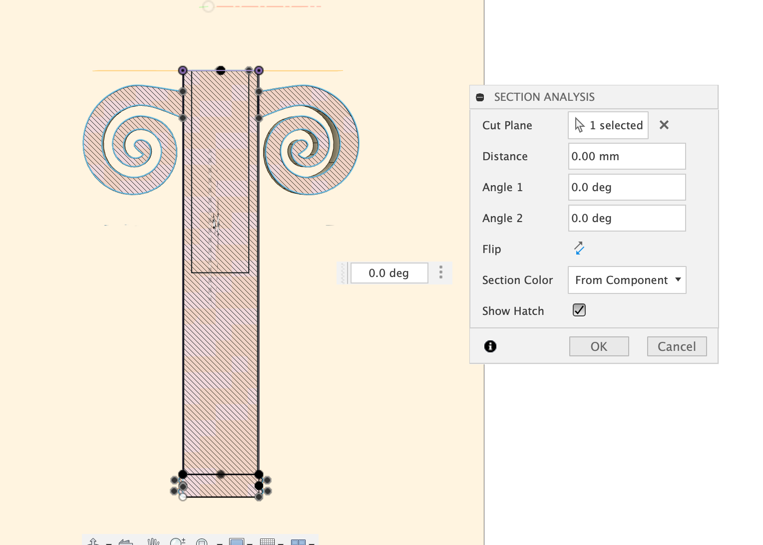
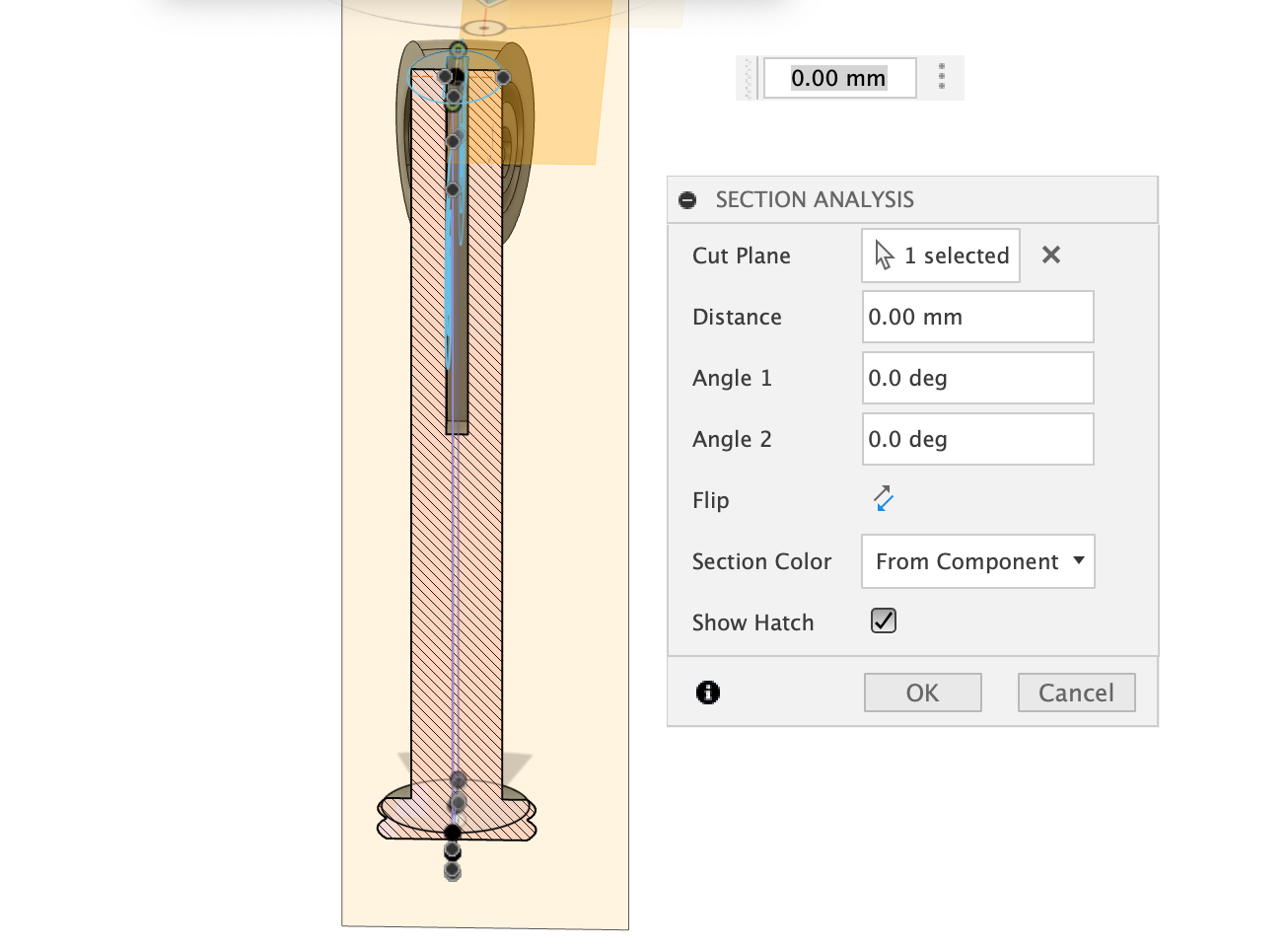
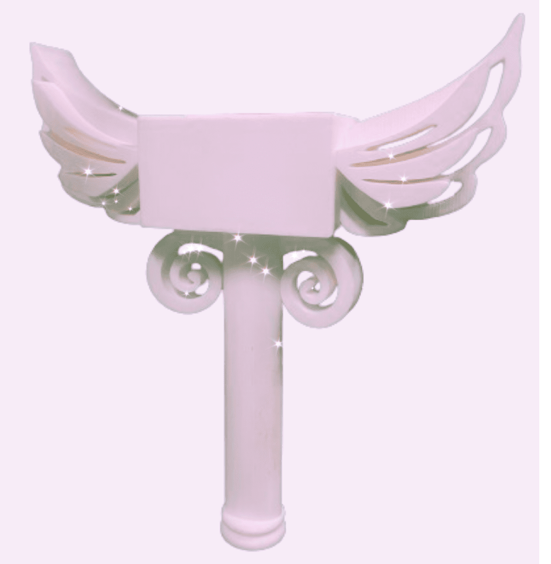
Final View of the box with Wings
Step5 Generate the STL file
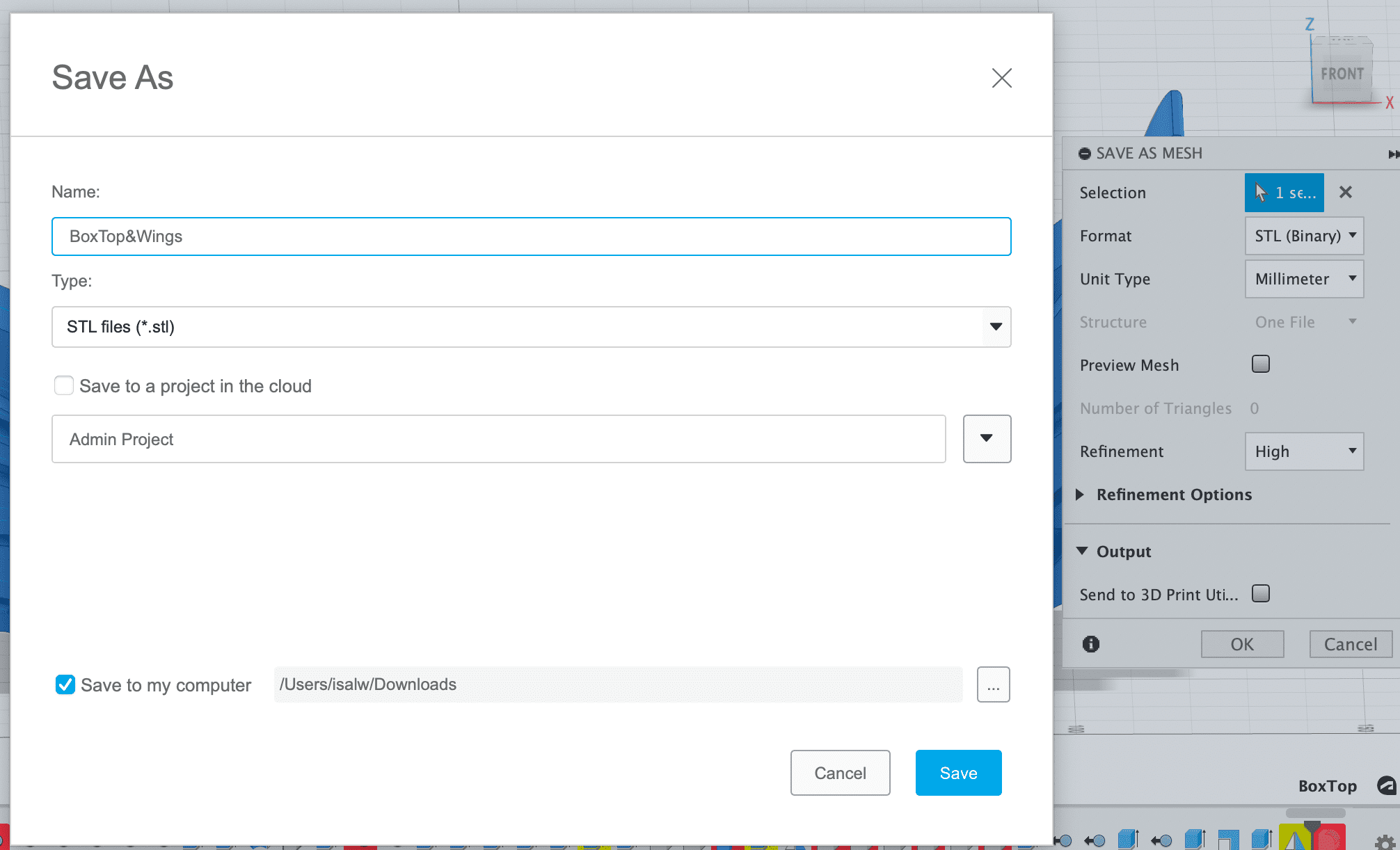
3. 3D Print
Importan Tips
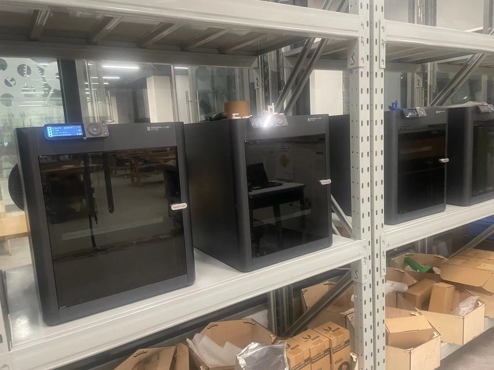
- A good 3D printer is really important, it will save you hours of work fixing the machine.Finally our lab has the new 3D machine Banboo Studio, which is perfect
- It is really import to choose the oritation of the object before printing and proper support type, because it will save you a lot of time to remove support.
Introduction of Bambu Machine
- The Bambu P1s module is a significant component in the realm of 3D printing. It is engineered with precision and incorporates advanced technologies to ensure superior printing results. The design of the P1s focuses on functionality and durability, enabling it to withstand the demands of frequent and complex printing tasks.
- One of the key features of the Bambu P1s is its compatibility and integration with various 3D printing systems. It offers seamless connectivity and control, allowing for smooth operation and fine-tuning of printing parameters. The module's performance is marked by consistent output quality and efficiency, making it a valuable asset for both hobbyists and professionals in the 3D printing field.
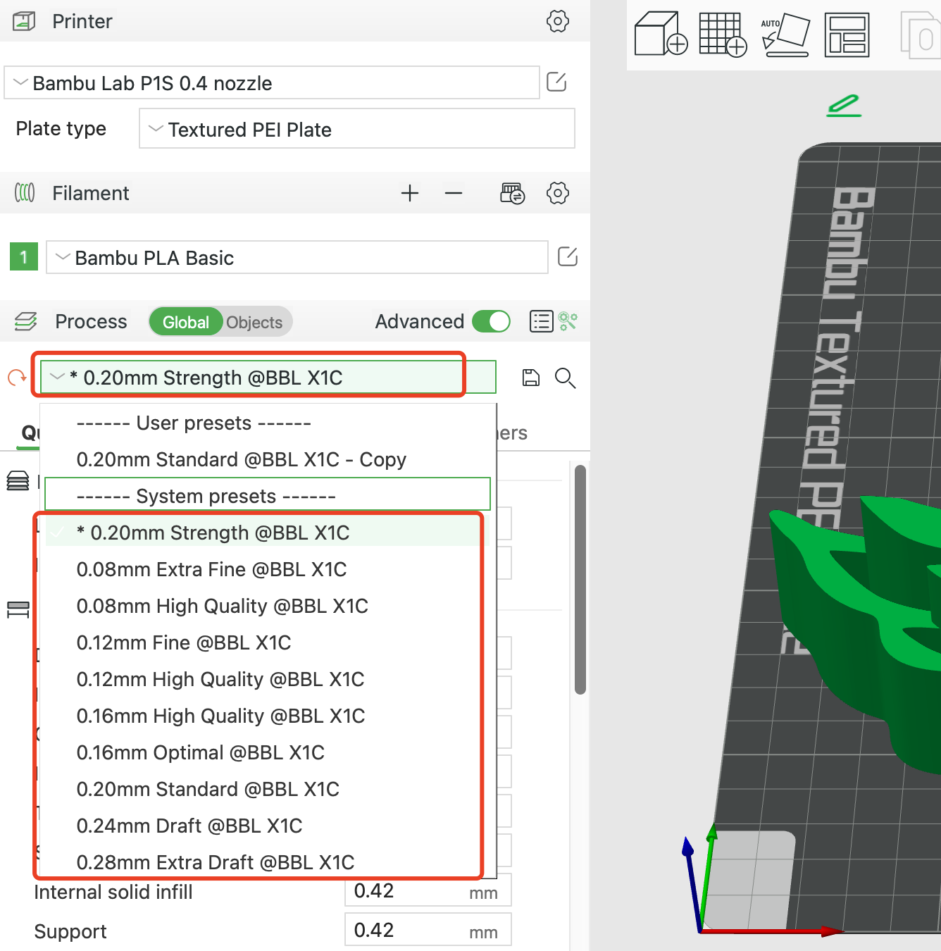
Generate G-Code
Install the bambu software then you can slice your stl file to g-code for 3D printing.
- Step 1 Load the stl file
- Step 2 Choose the Quality of Printing
The default quality is already good enough.
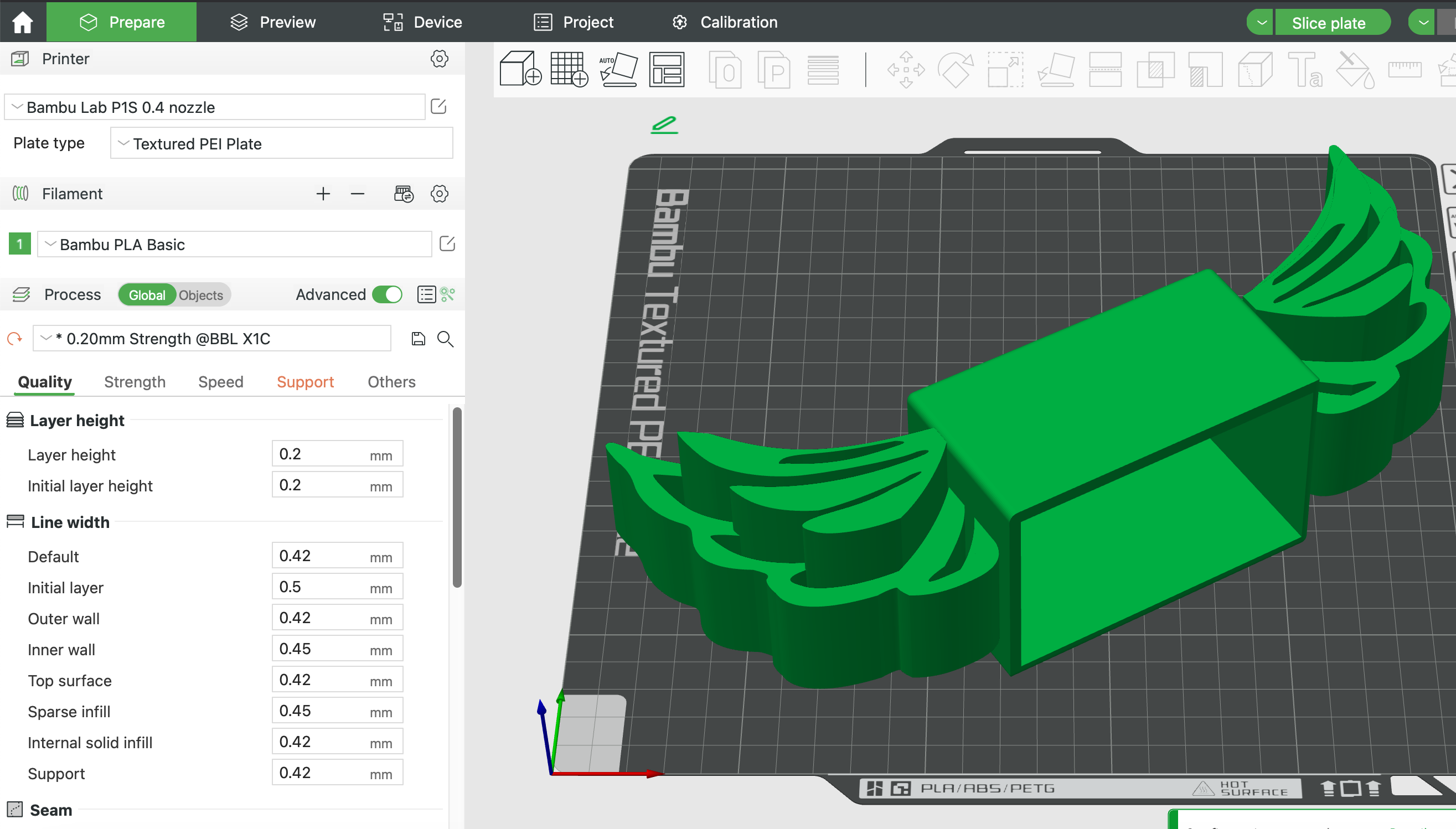
- Step 3 IMPORTANT! Choose the Correct Oritation and Support
The printing placement direction and the type of support directly determine how painful it is to remove the supports later
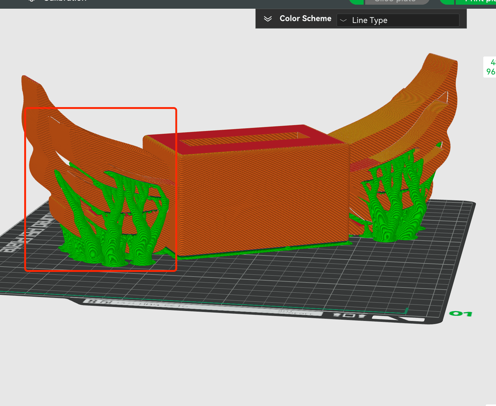
For a hollowed-out structure like mine, if normal supports and the normal placement direction are used, there will be a lot of supports in the gaps that are extremely difficult to remove.
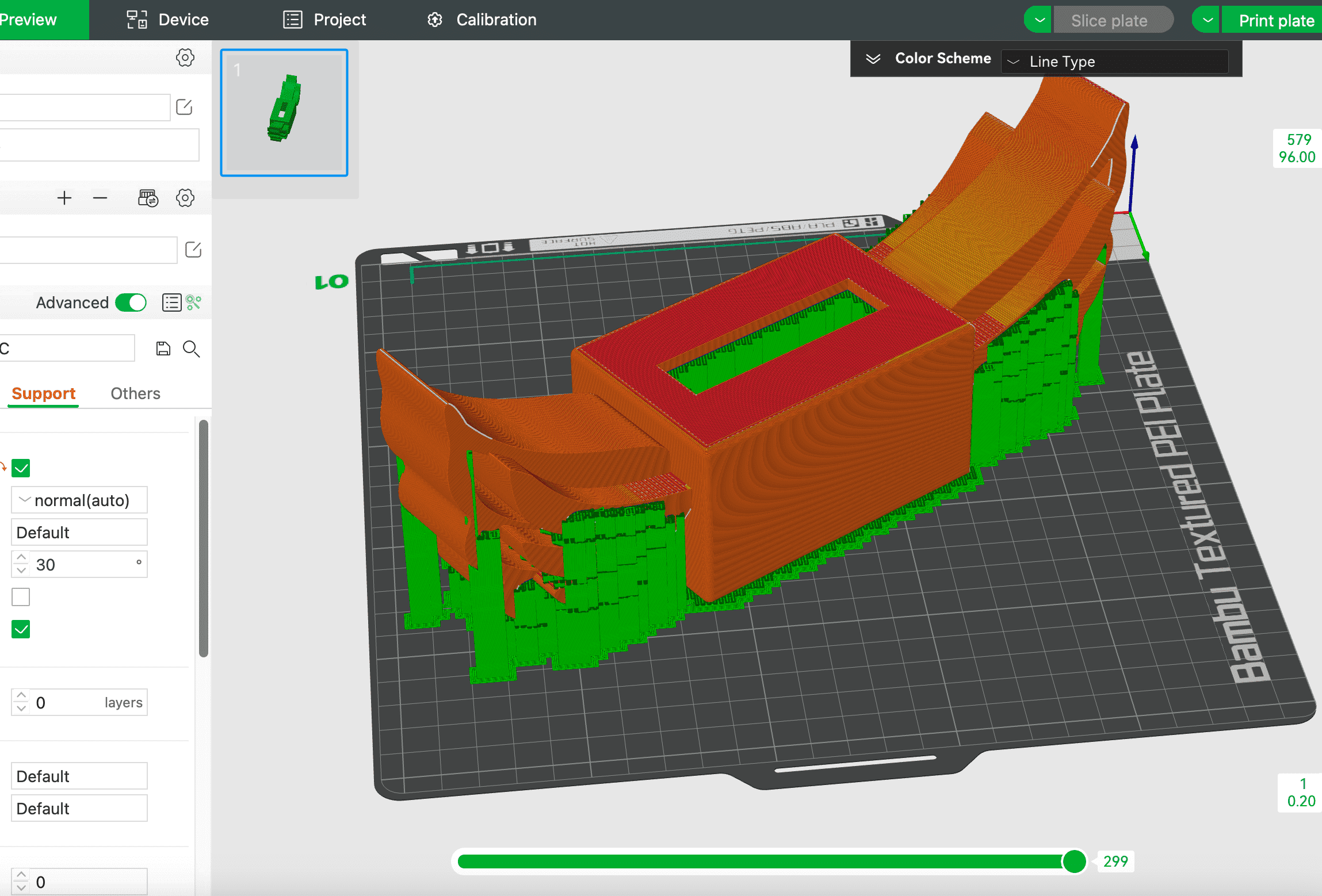
Tree support may looks better, but actually still a lot of supports in the gaps.
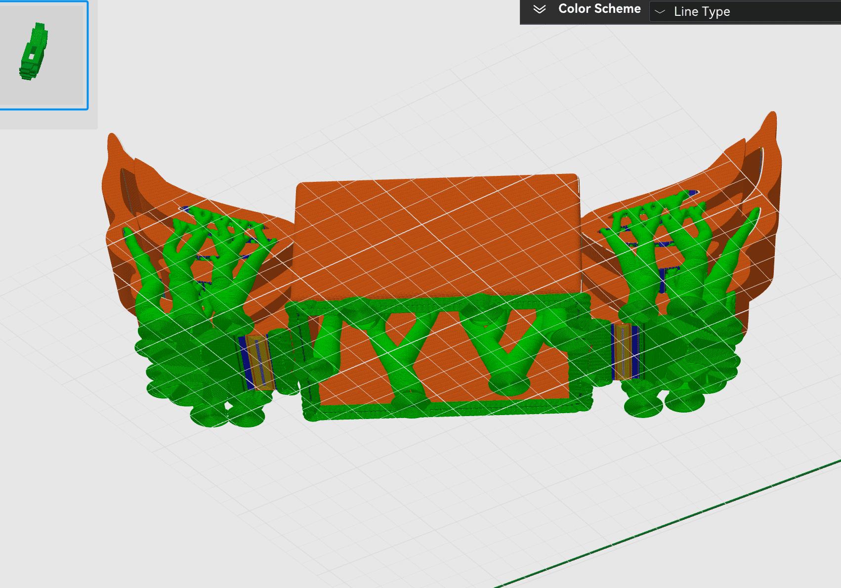
So it is very important to try lay the object using different oritation, such as below:
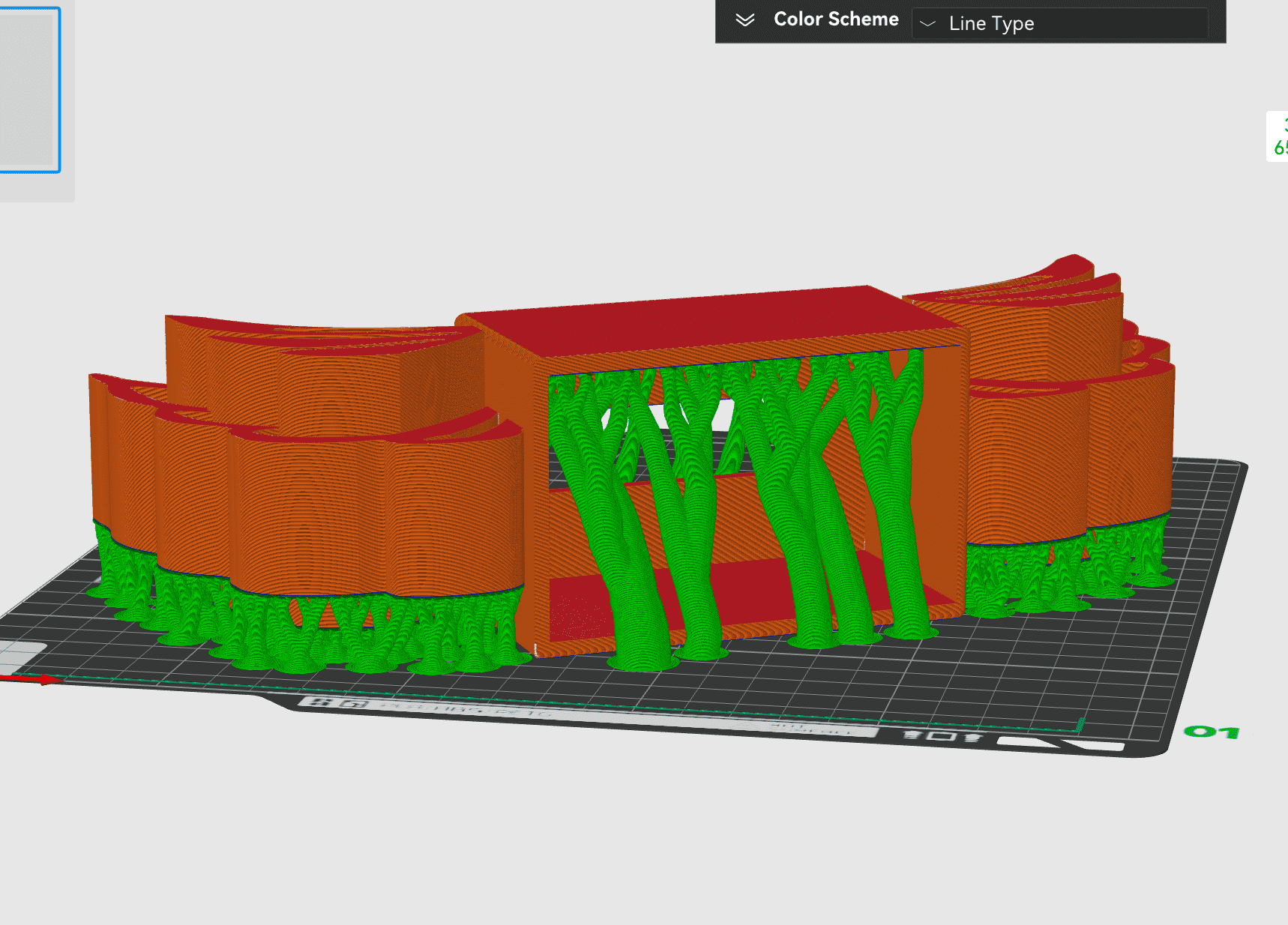
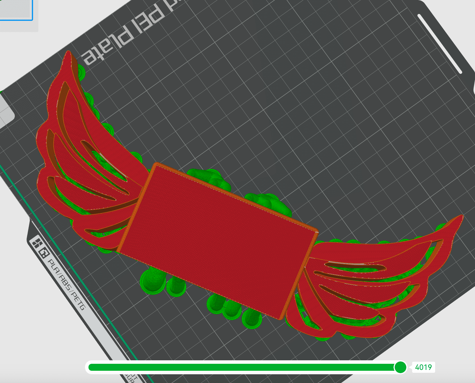
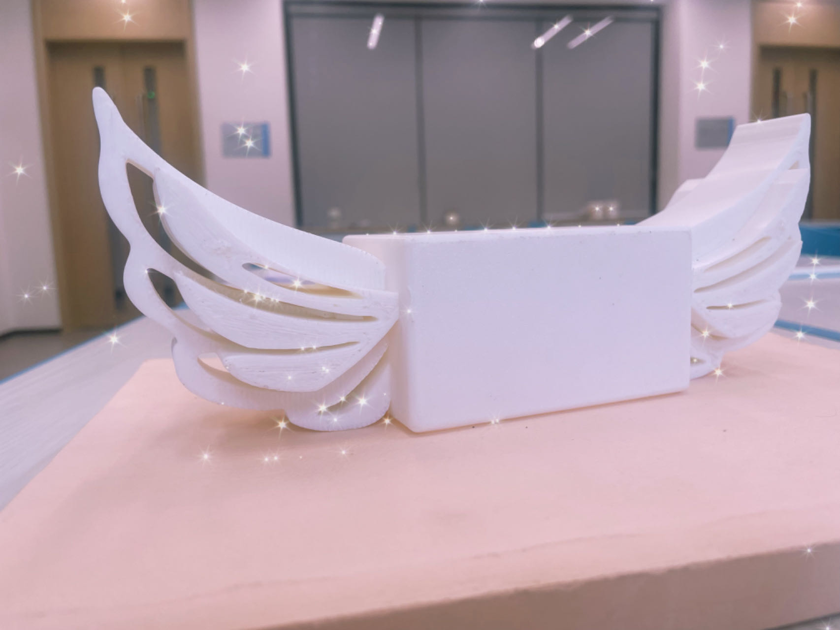
You can see that there is not too much support to remove and the gaps are mostly clear.
Step 4 My Final Beautiful box with wings
Part 2. 3D Design of The Handle part of my Sword
The 3D design and printing part is mainly divided into two sections:
- One is the downward-buckled sword case and wings, where a gap for the upper sword blade needs to be reserved.
- The other is the lower part of the upward-merged sword case along with the hilt.
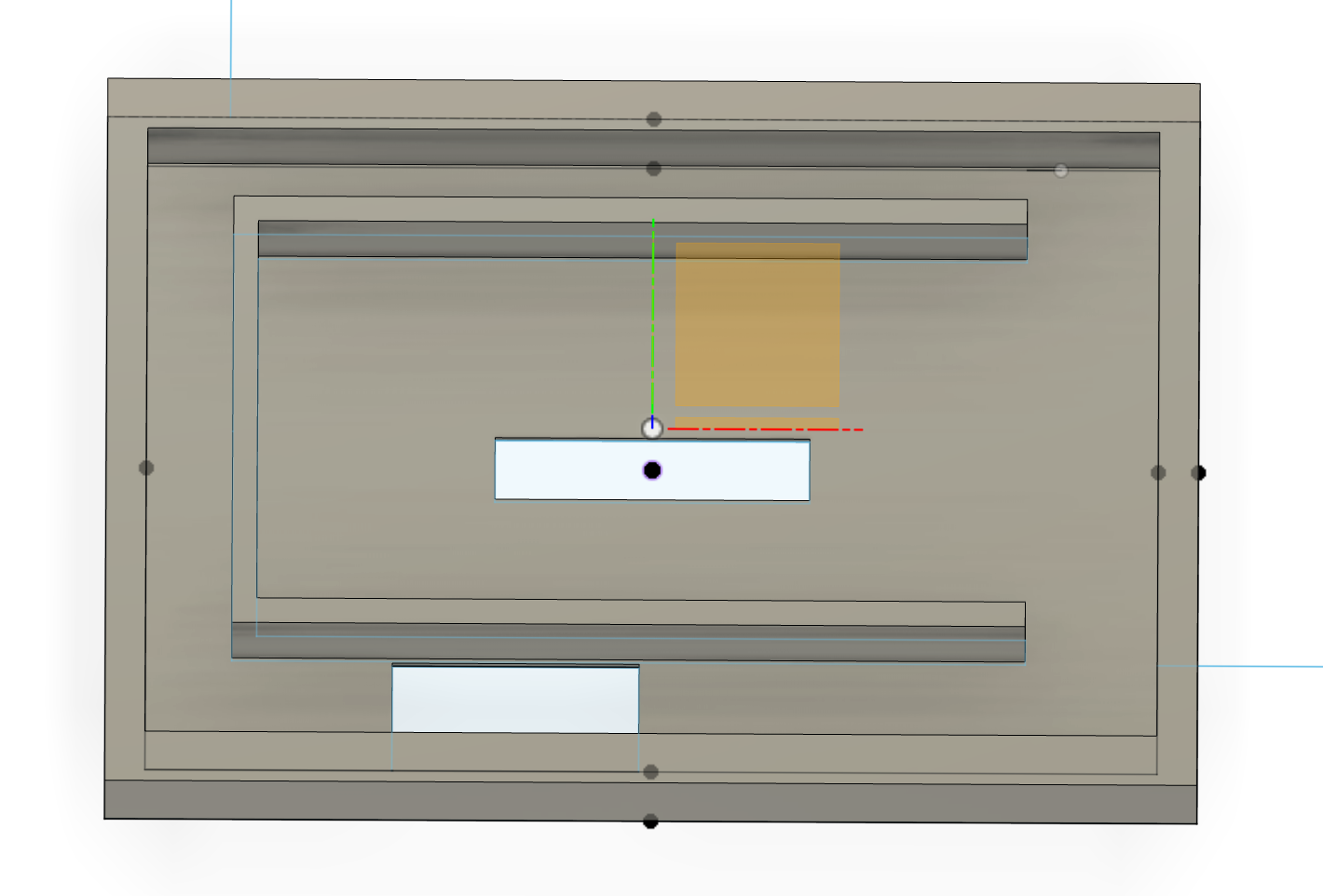
Design of Lower Sword Case
The design process of lower part of the upward-merged sword case along with the hilt will be as below :
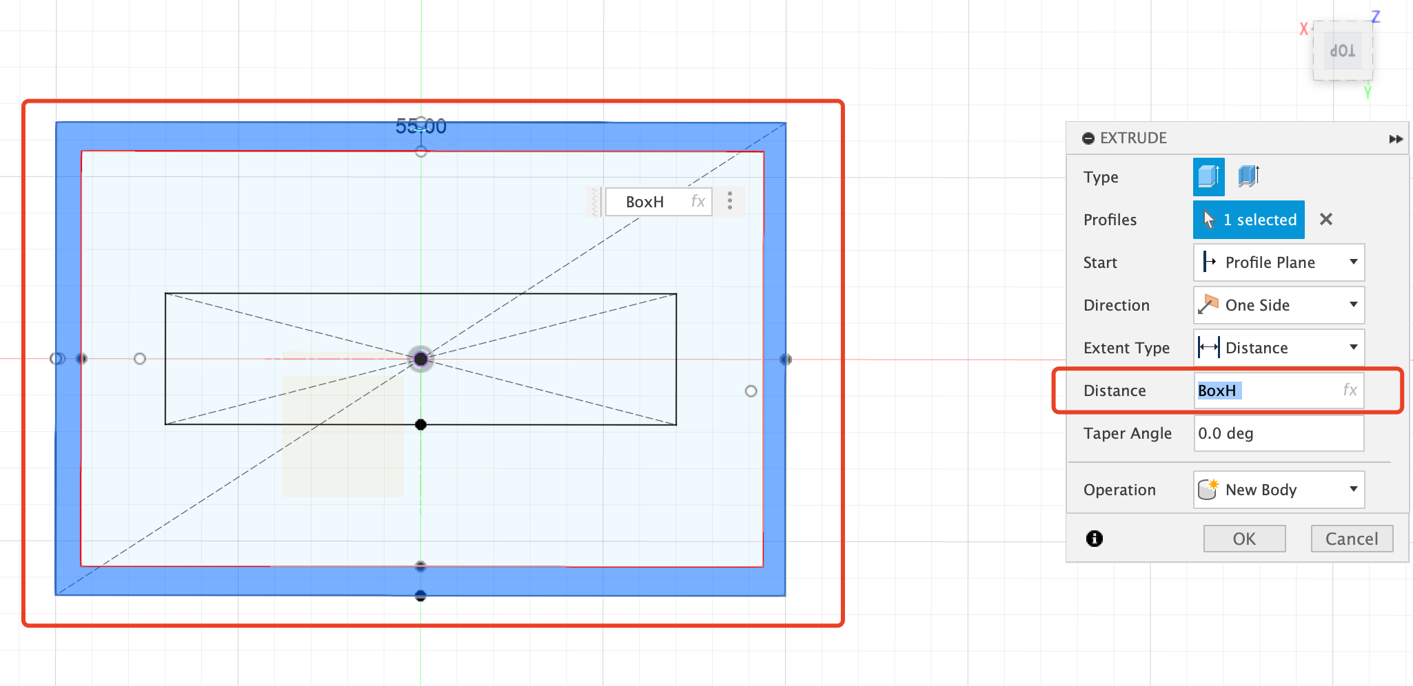
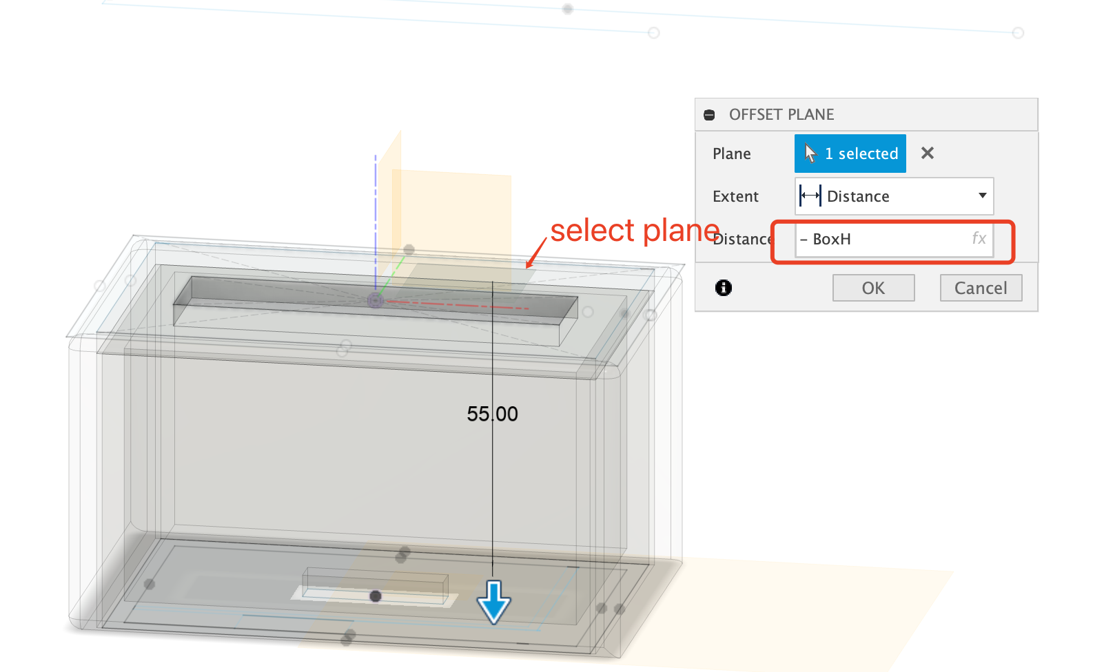
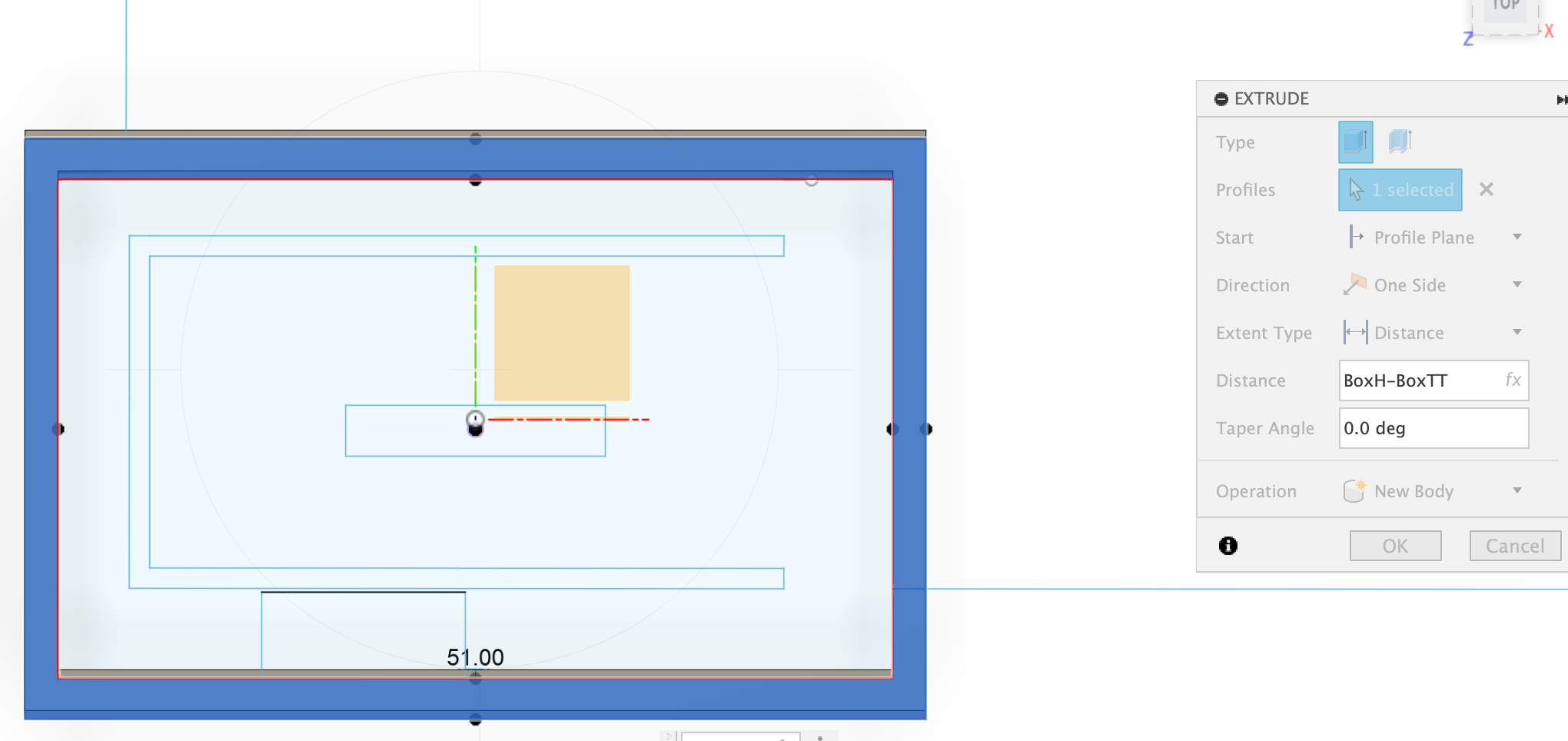
1. Set up the plane First
The plane of the lower sword case should be at the bottom of the top case :
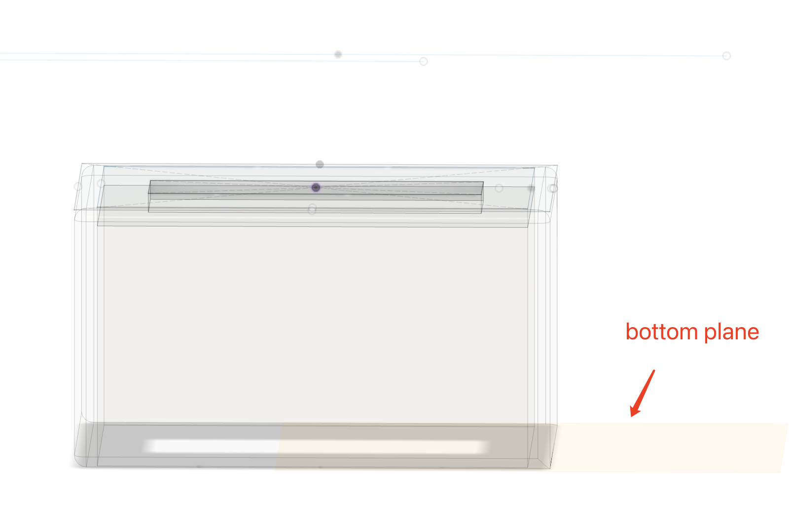
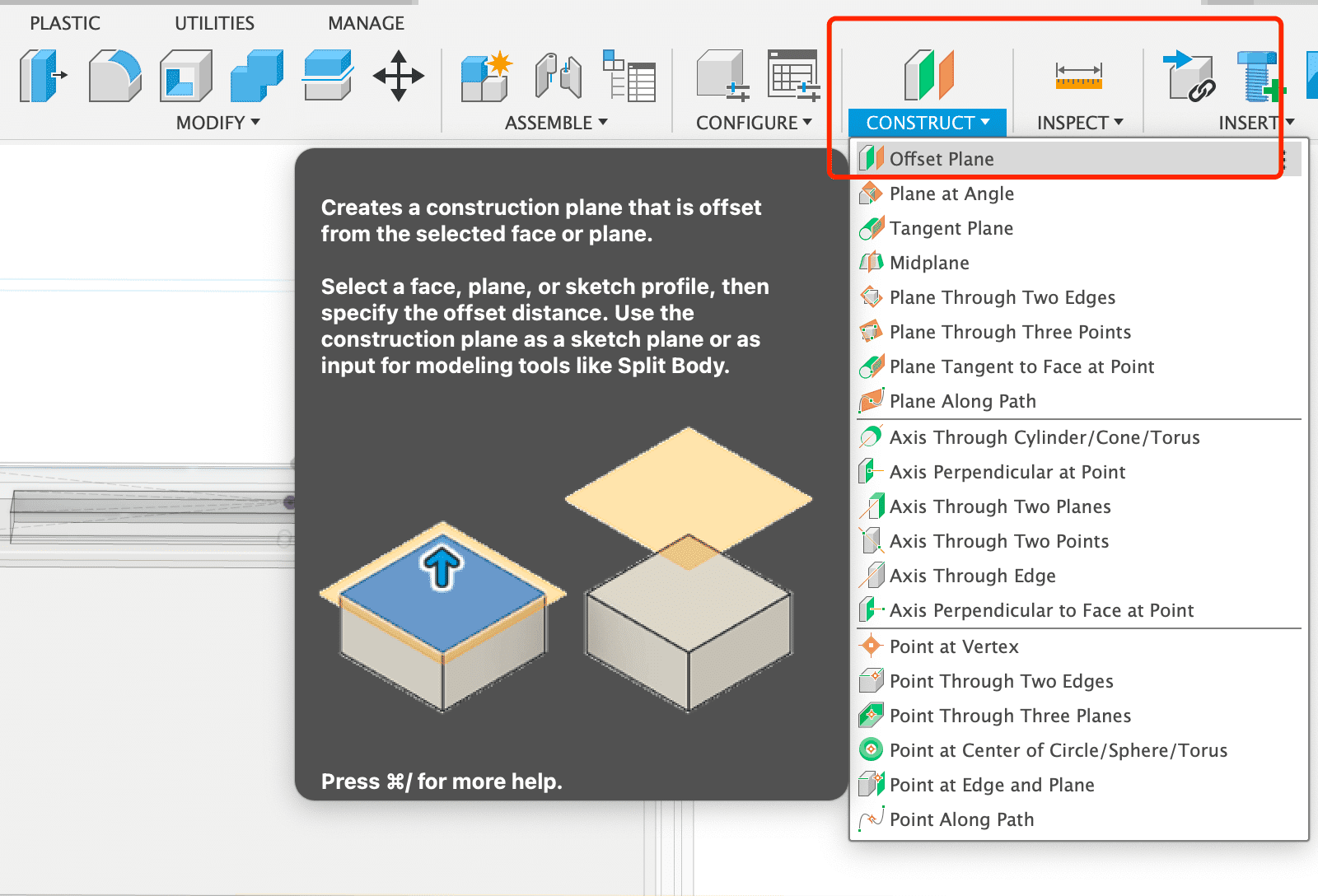
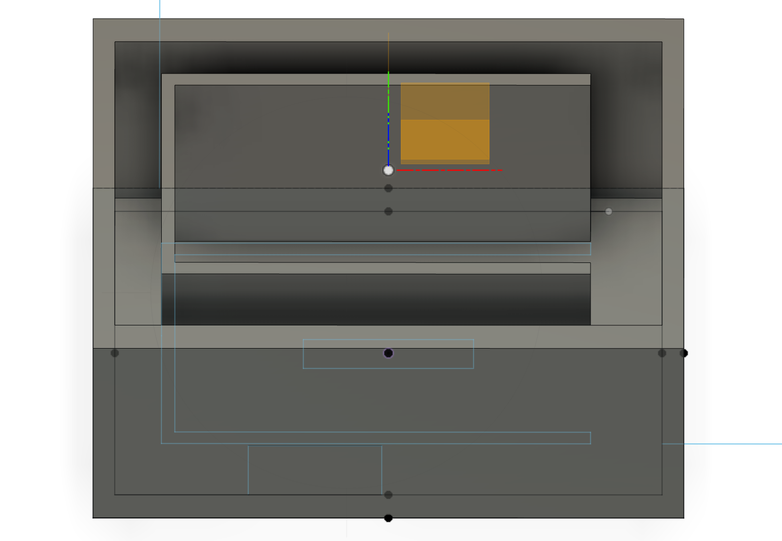
2. The offset value should be the height of box case
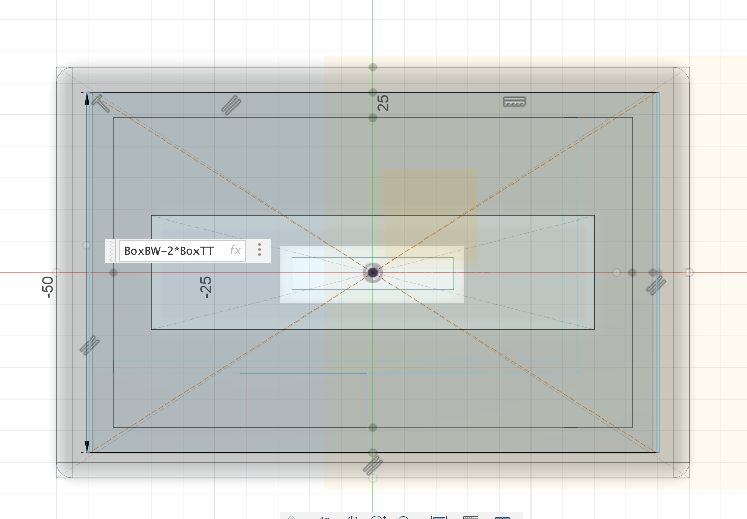
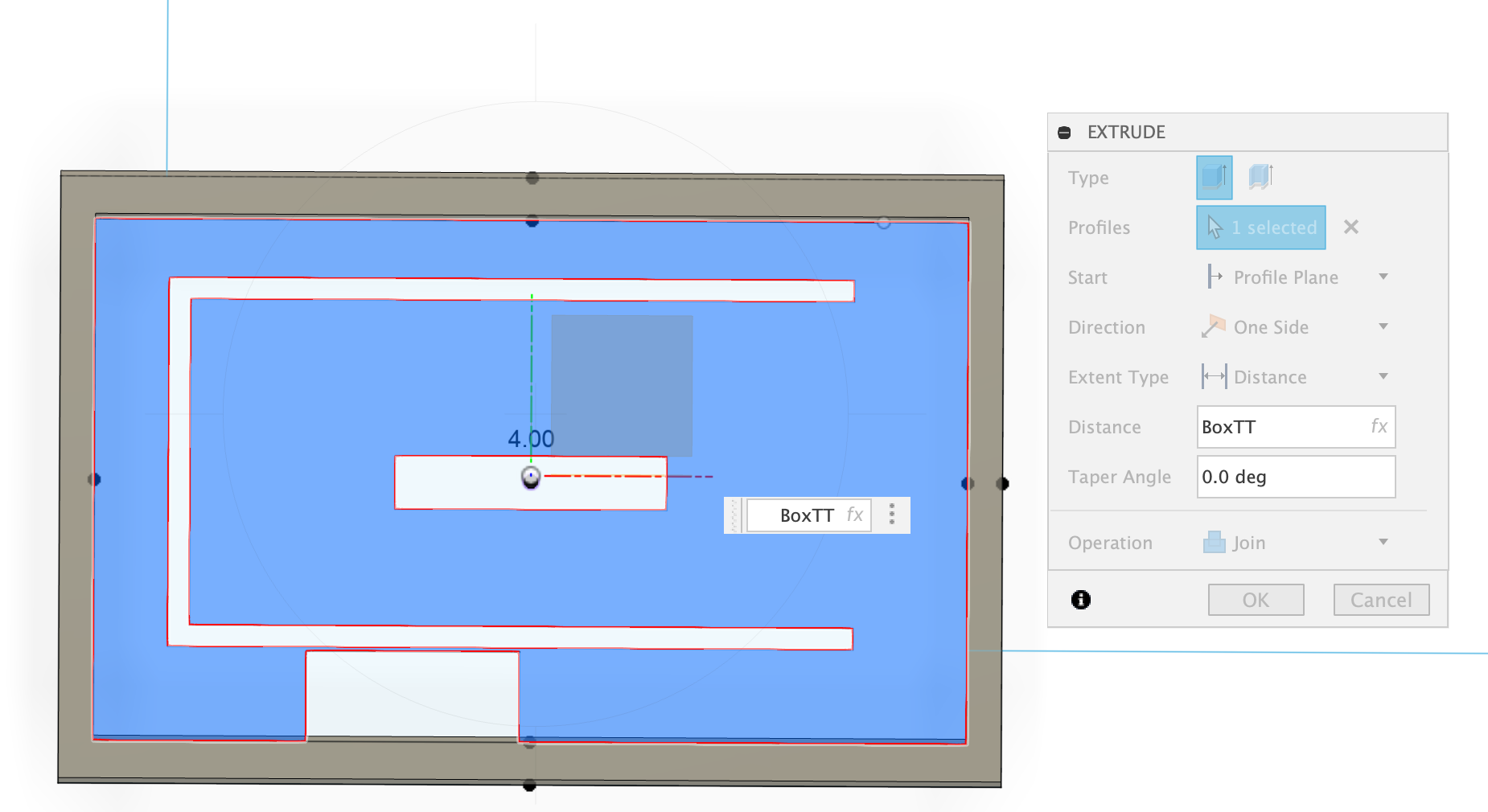
3. Create the sketch on the offset plane
first draw a centered rectangle, calculating the parameter and set the width of the box to be BoxW minus 2* thickness.
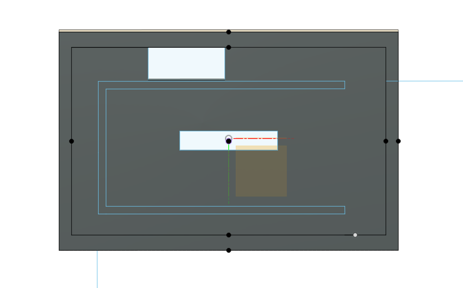
4. I will illustate all the important calculation of the case as below:
4.1 The outter part of lower case needs to be inserted into the upper case, so the length is calculated based on the upper case box length and minus 2* thickness of box, and minus 3.5mm considering the kerf of 3D printer
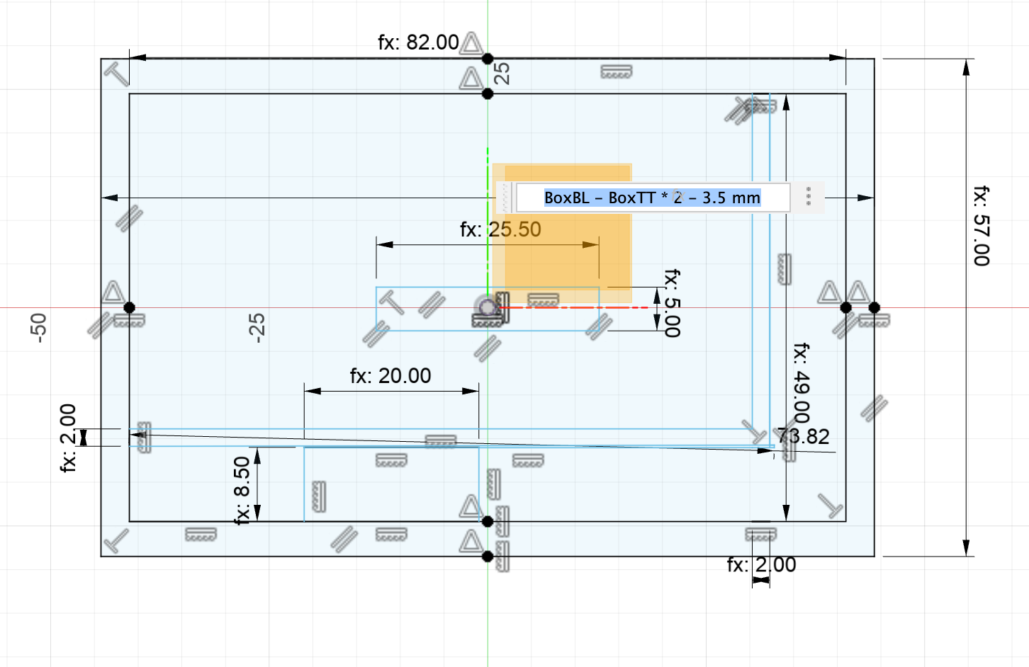
4.2 The inner part of lower case length needs to be upper box length minus 4 * thickness of box -2mm for kerf
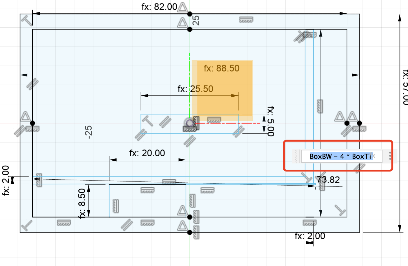
4.3 The inner part of lower case width needs to be upper box width minus 4 * thickness
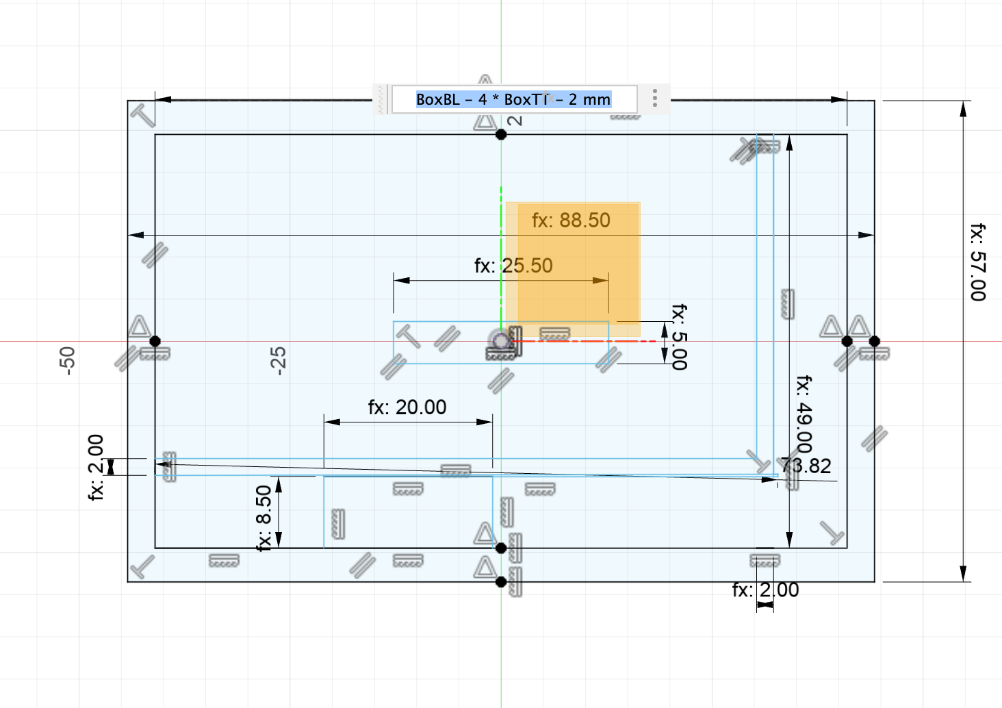
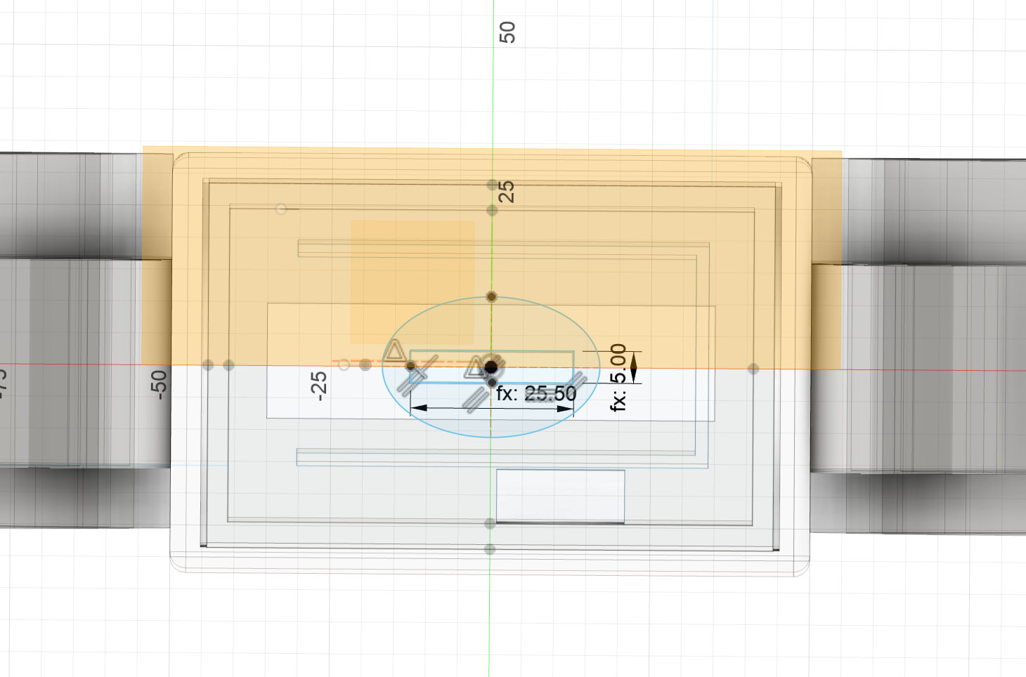
4.4 Align all the center point of the rectangles
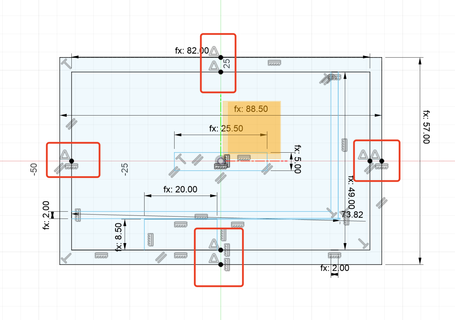
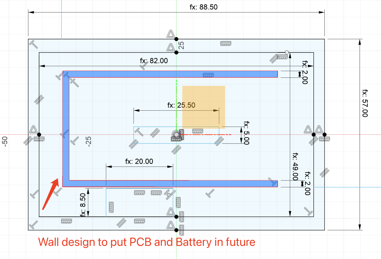
4.5 Build up the wall to put the PCB and battery in the future design inside the gap of the box to make it more stable.
4.6 Make the connector hole to put the connecor,increase the length 0.5mm considering the kerf of 3D print and easier to put the connector inside
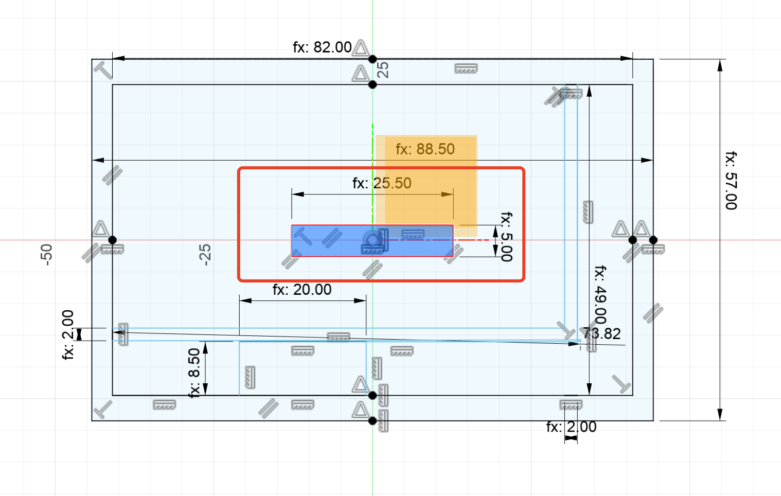
4.8 I also made a hole here to connect the typeC line inside for the PCB
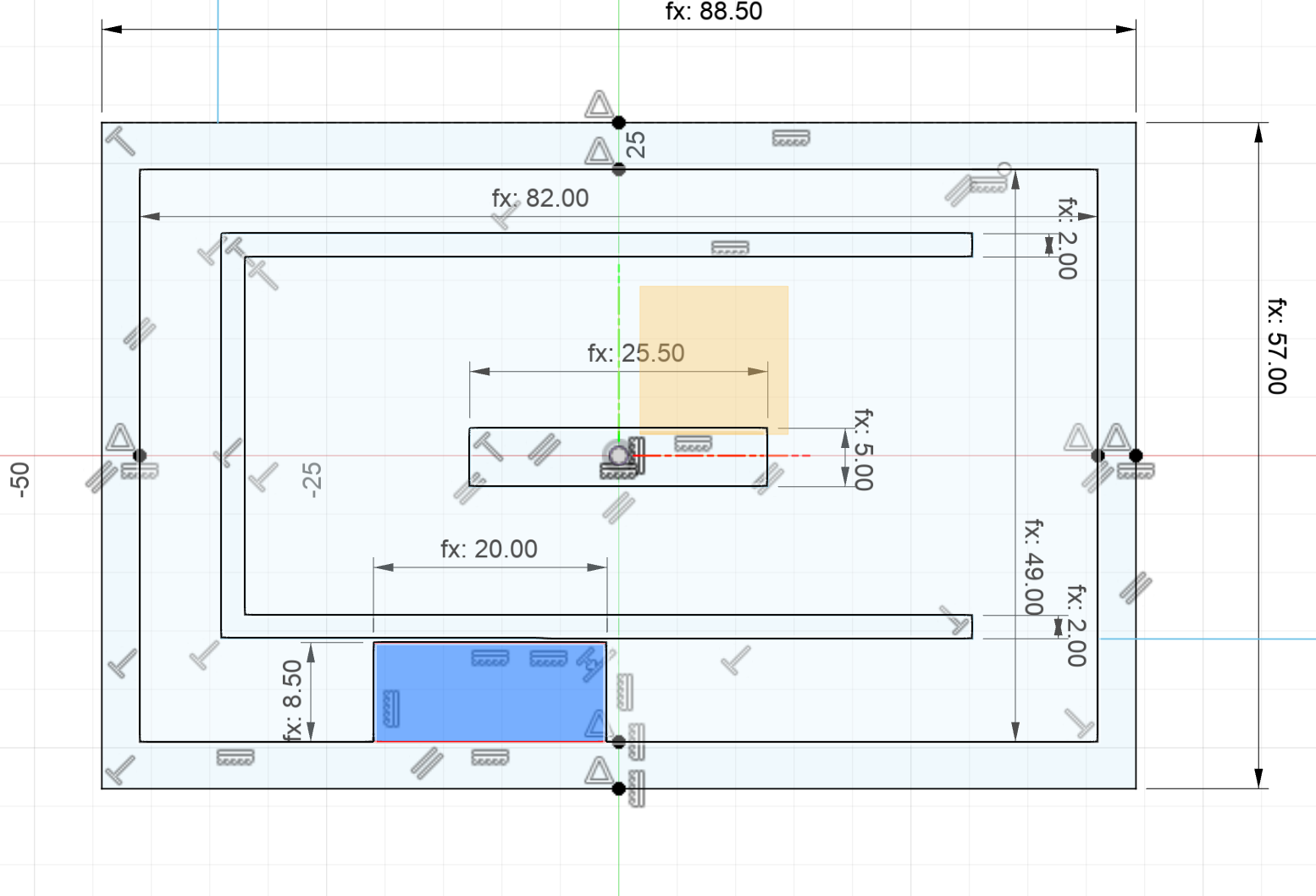
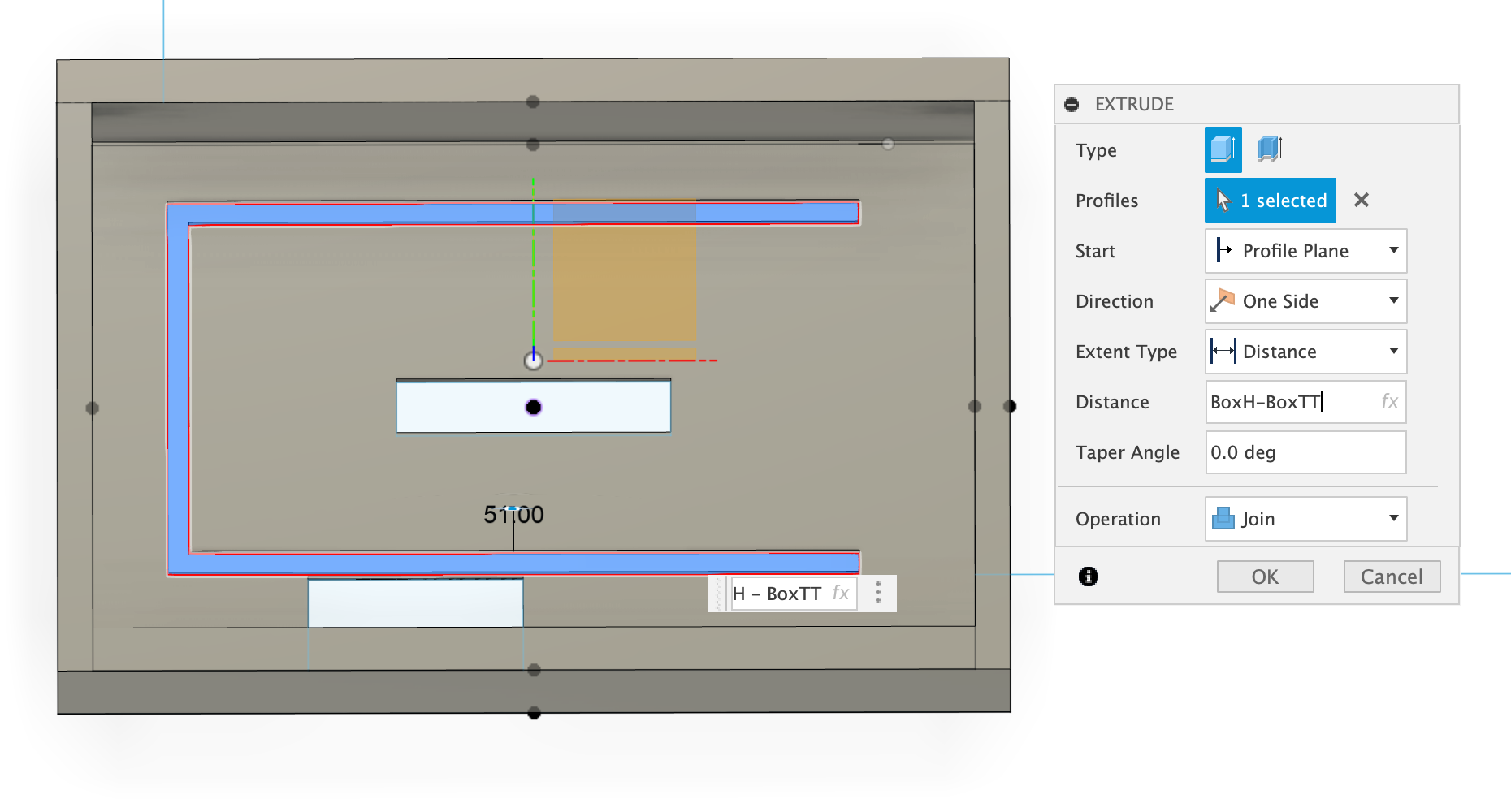
4.8 Extrude the box, then extude the wall inside
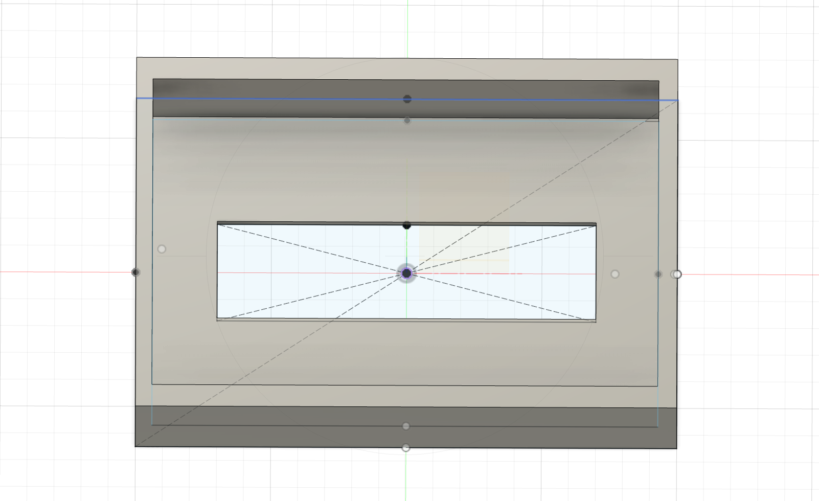
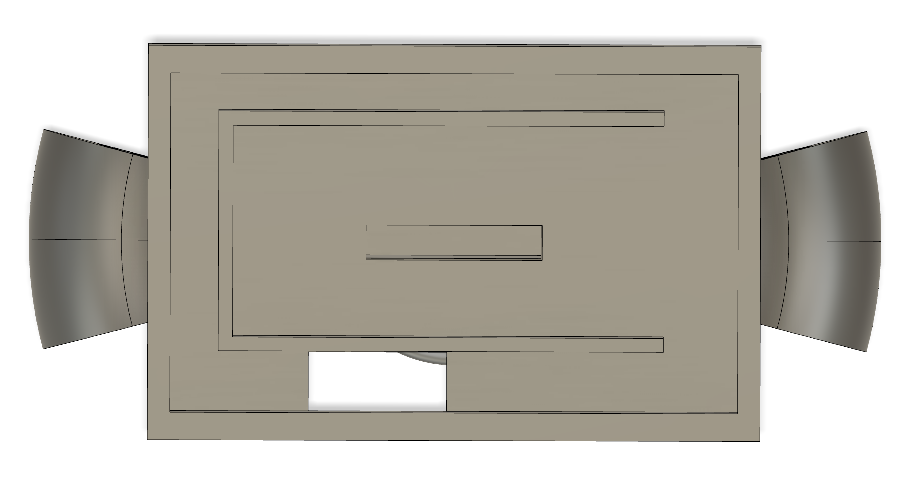
4.9 The final side view of the case
4.10 The final bottom view of the case
5. Design of lower Sword Handle
5.1 Create ellipse on the bottom plane
5.2 Extrude the ellipse
5.3 Project the body of the elliptical
5.4 Create a sketch on front panel and draw a rectangle based on the projection line, then import the svg file for the handle design.

5.5 Unfix the svg imported
5.6 Remove the unwanted lines
5.7 Move the ear part to the right position
5.8 Cut the unwanted lines on the ear
5.9 Extrude the ear on the handle
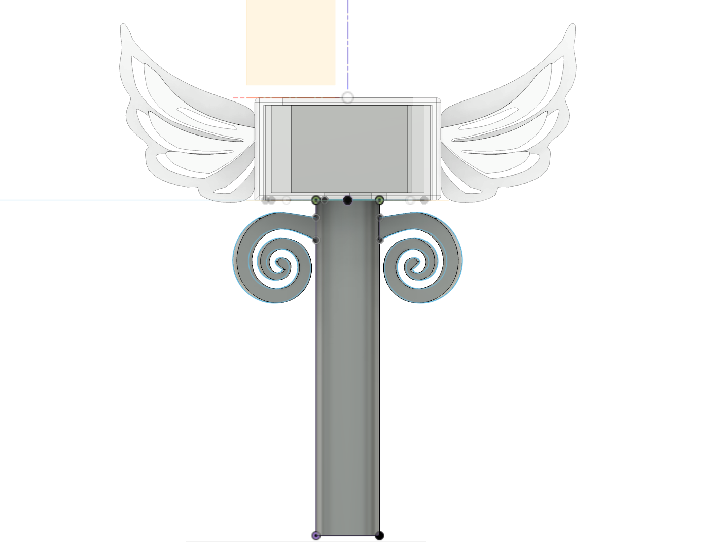
5.10 Mirror the ear object to make it Symmetric
5.11 Make the bottom part's sketch. First choose offset plane
5.12 Create a circle. Set the diameter of the circle as the longer diameter of the ellipse, and align the center of the circle with the center of the ellipse.
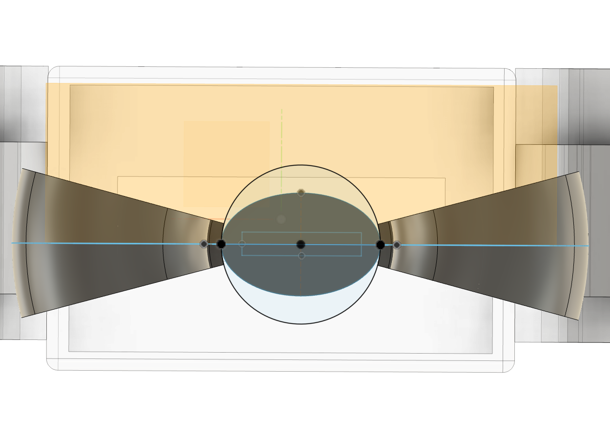
5.13 Extrude the circle
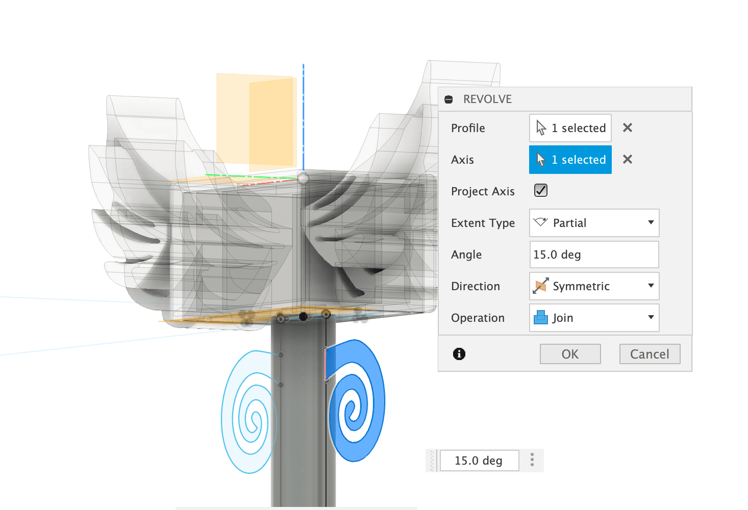
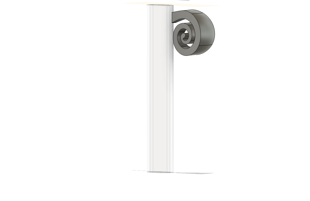
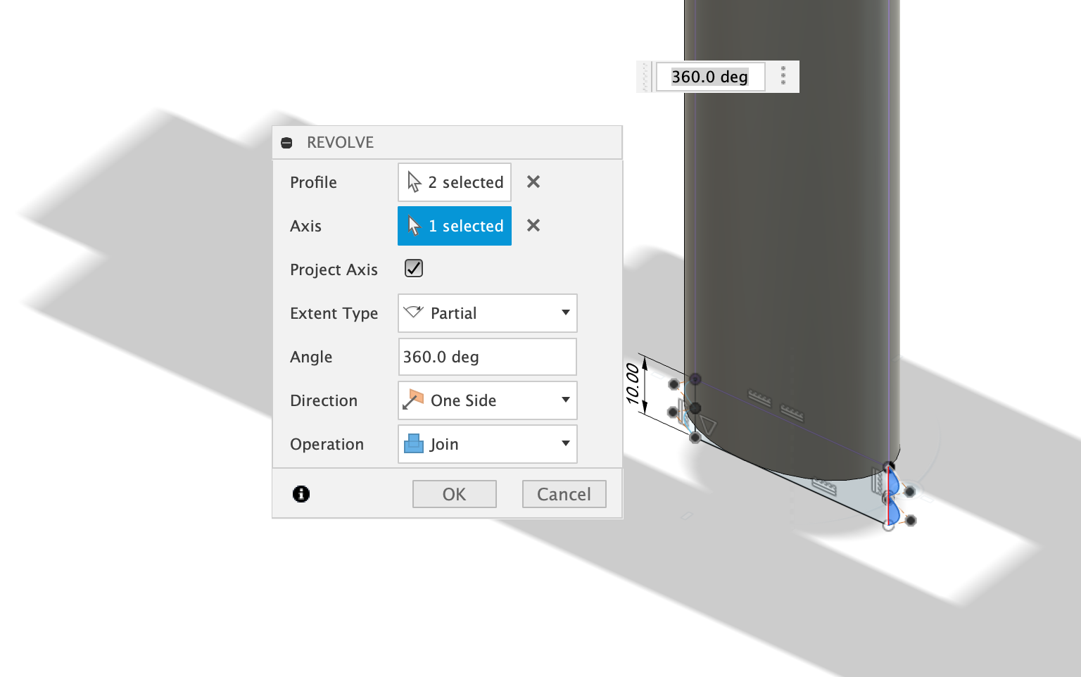
5.14 Go back to the projected handle sketch and draw the protruding edge curve for the lower cylinder of the handle.
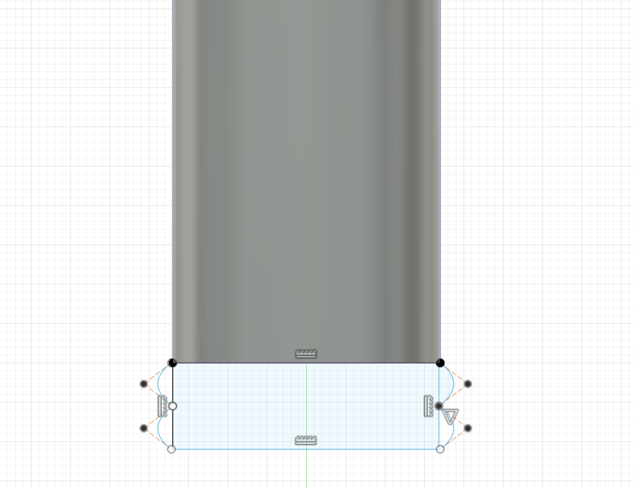
5.15 Use revolve to extrude the protruding edge curve
5.16 The handle part is done!
5.17 You can also inspect to check if the inner part of the handle is right or not.

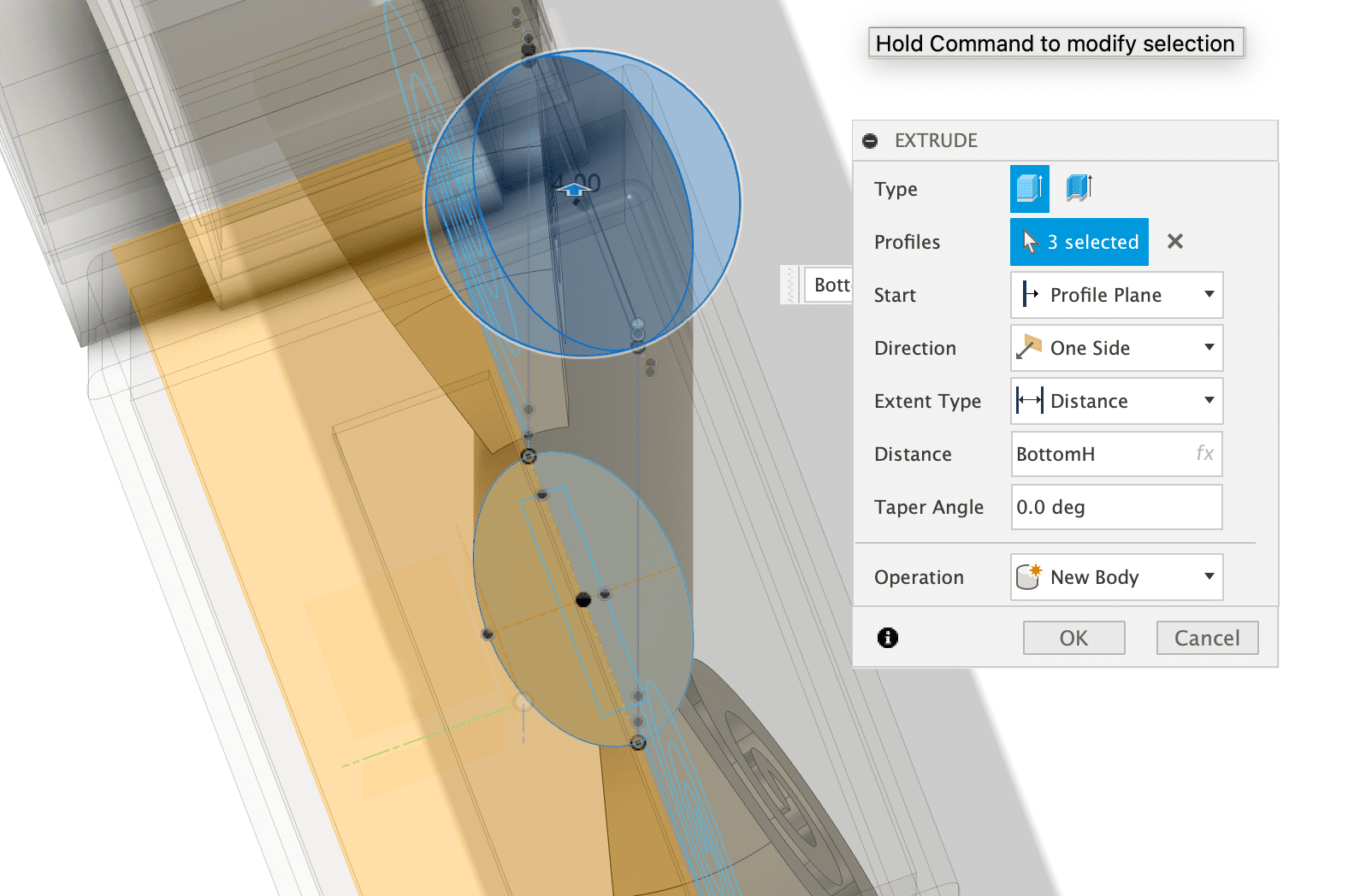
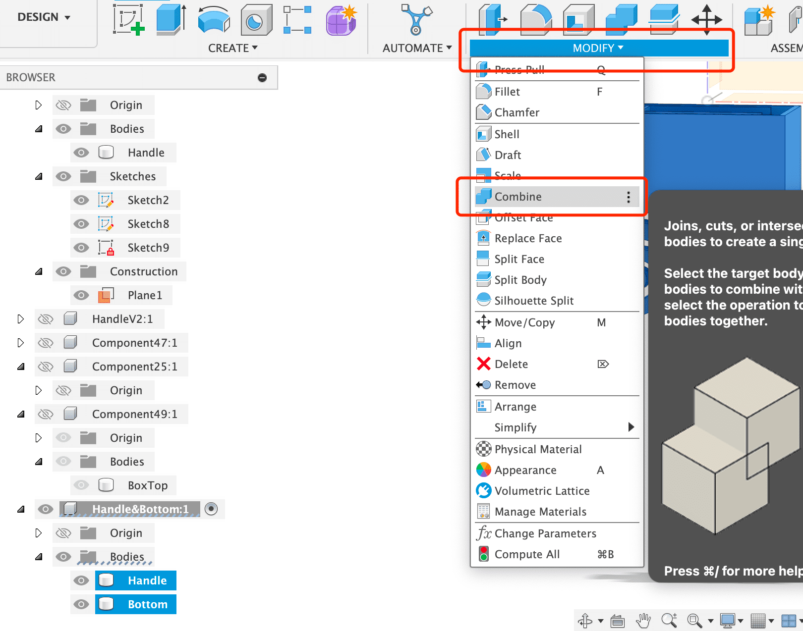
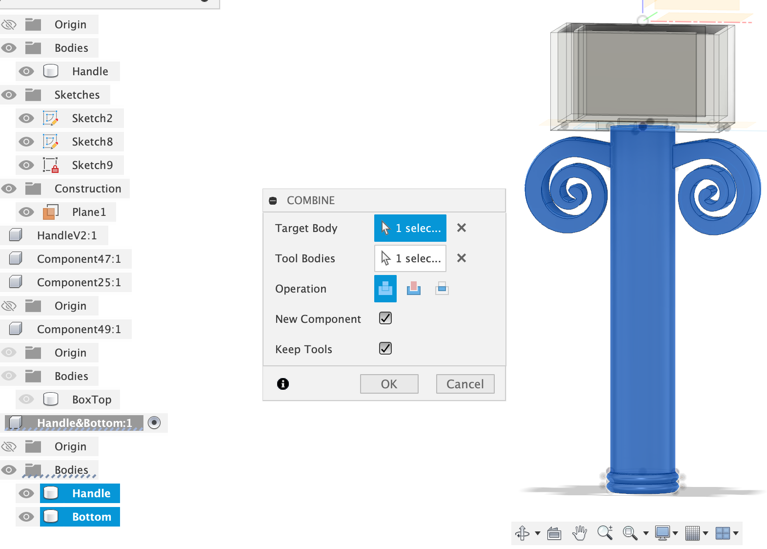
6. Combine the lower sword case with the handle.
6.1 Create a new component
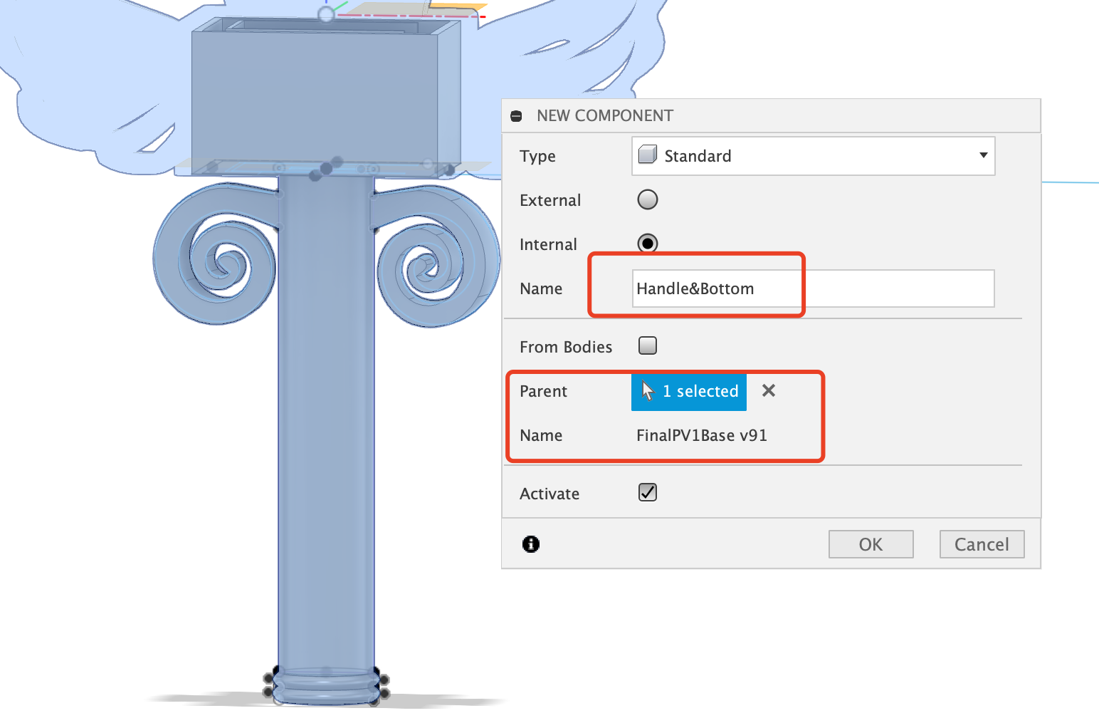
6.2 Copy both the lower case body and the handle body into the new component
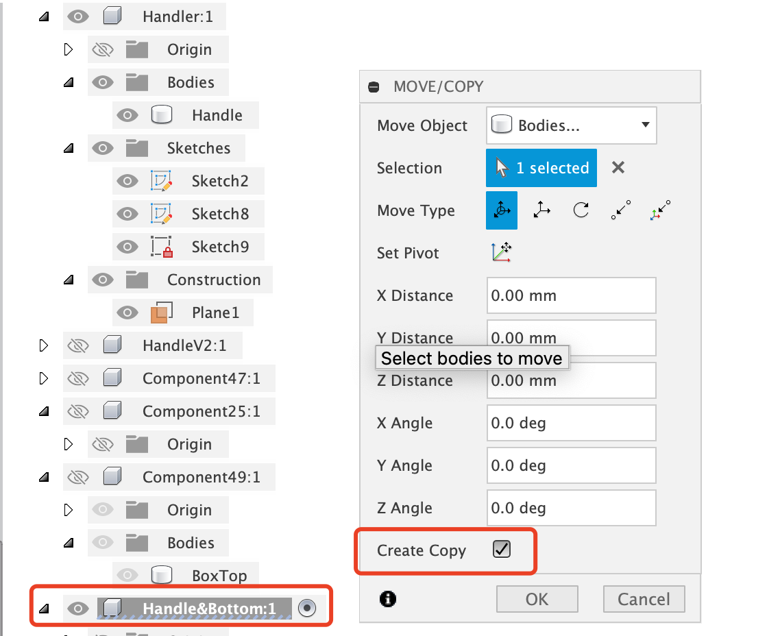
6.3 Finally combine the two bodies to a new body
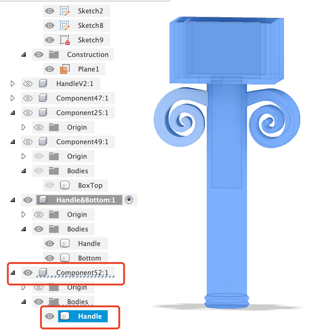
6.4 Final View of the sword handle with lower Case!
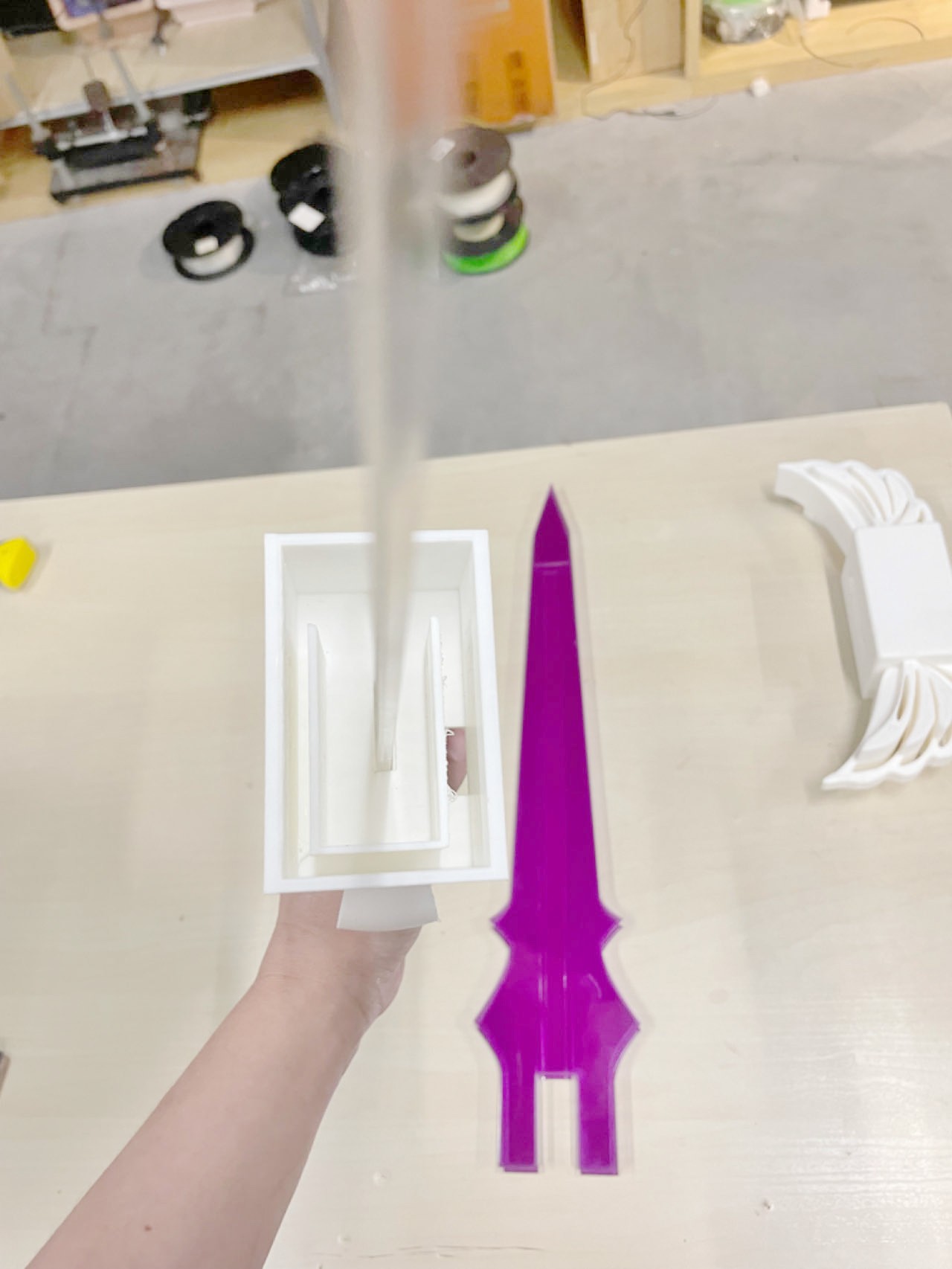
7. Export the stl file and then slice it in bambu software
Still I used the tree support and put handle down to print.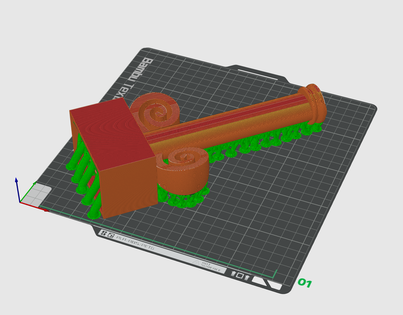
8. Finally 3D Printed
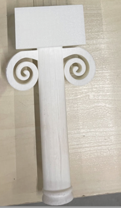
9. Top and Handle Together!
Part3 3D Scan
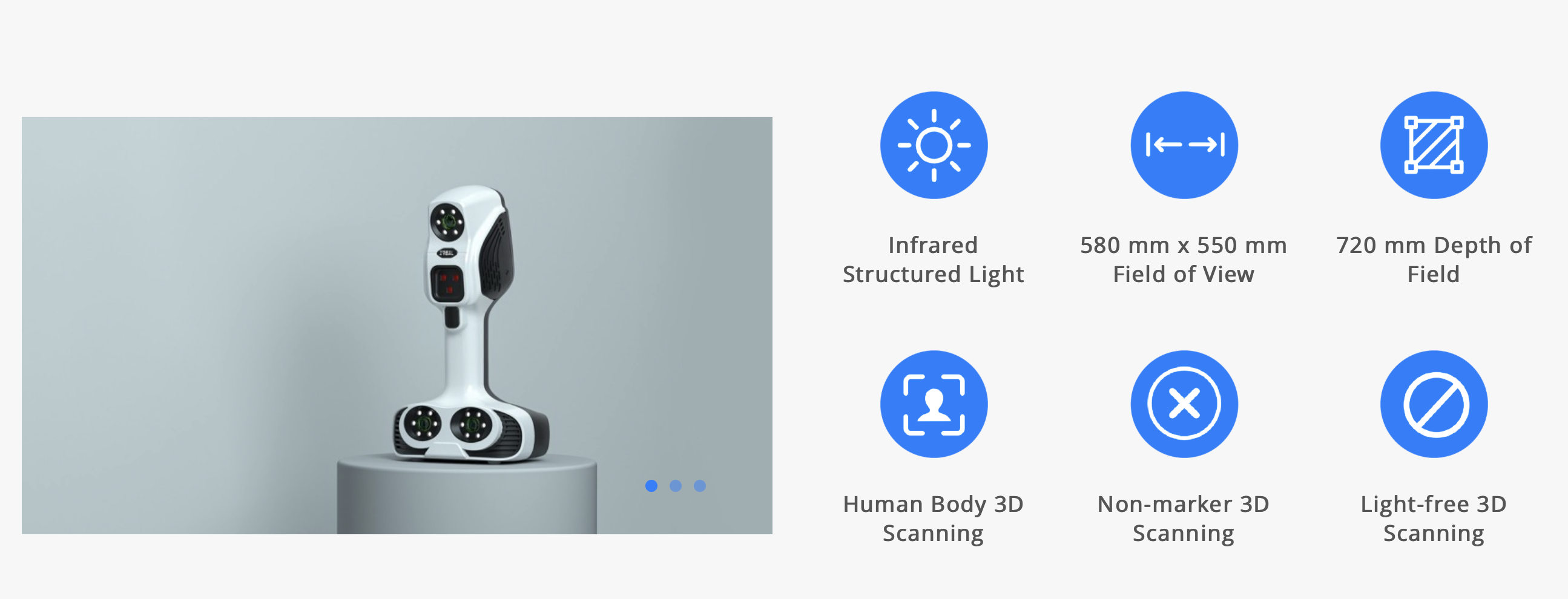
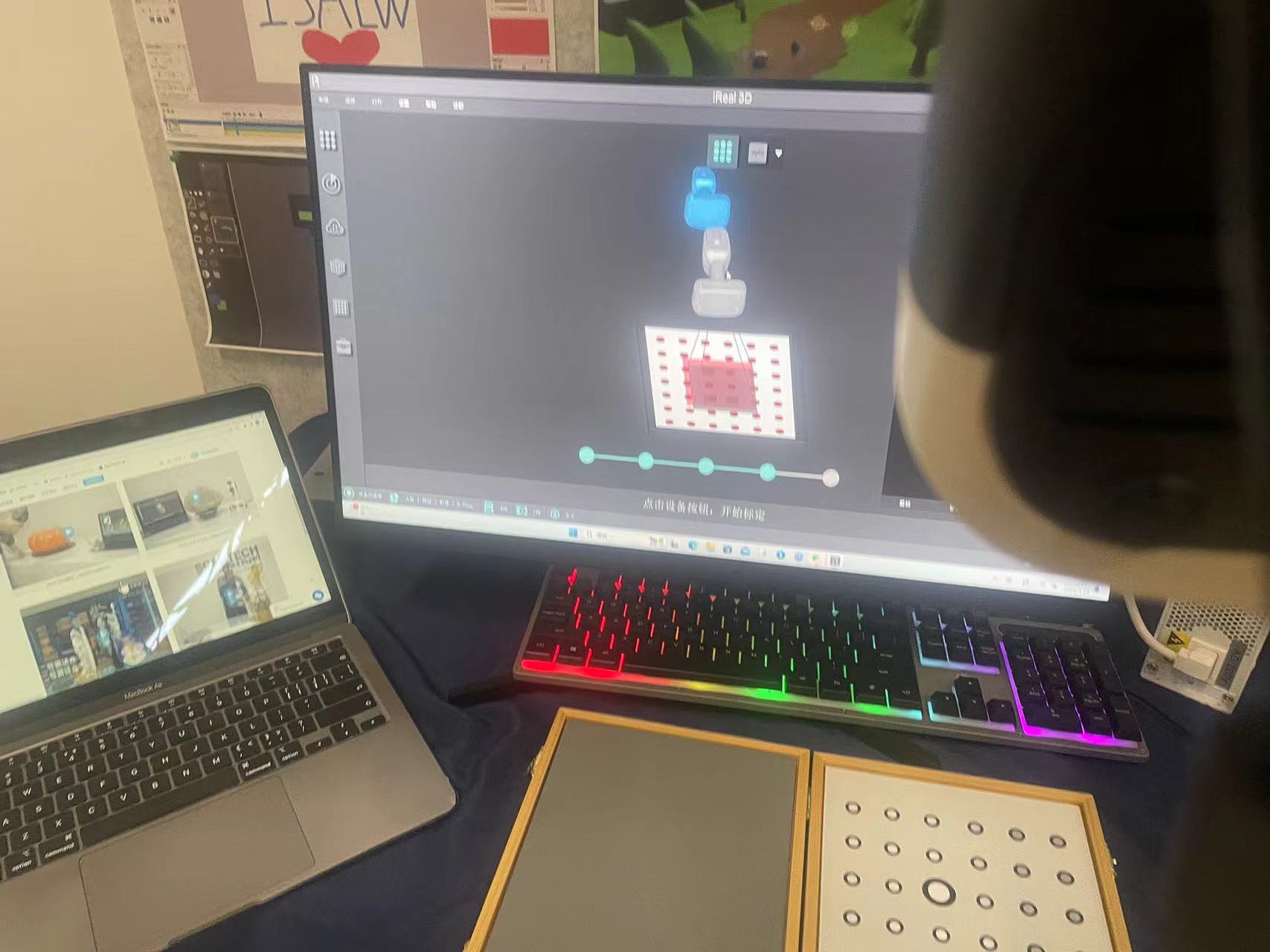
The 3D scan machine I used is IREAL 2E 3D BODY Scanner
iReal 2E 3D body scanner maximizes the performance in depth of field, scanning area, algorithm, texture reproduction and detail capturing, specially designed for medium to large-sized objects and human body 3D scanning.
iReal 2E 3D body scanner adopts the infrared VCSEL structured light technology to bring you the safest and most comfortable 3D scanning experience. Without attaching markers, a quick texture capturing and geometry acquisition can be achieved. Mixed alignment modes meet various scanning situations.
Step1 Get the hardware and Software Ready
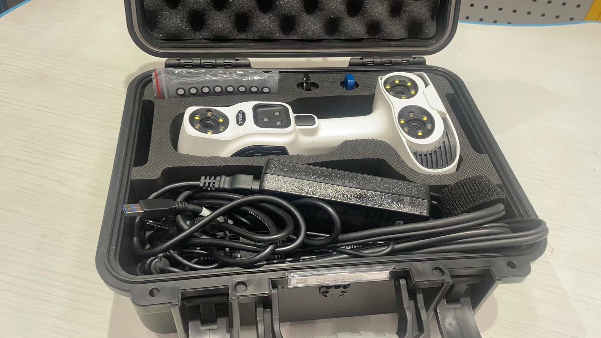
 Missing a pic for 3D software
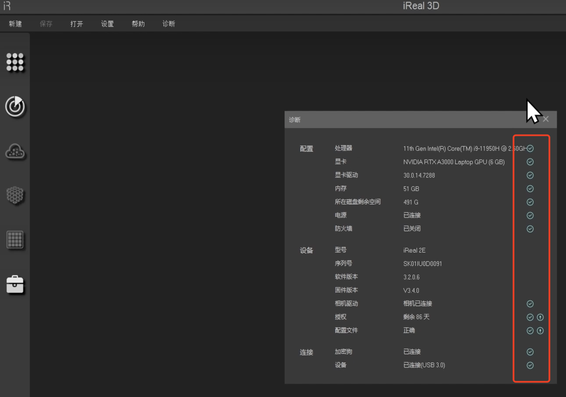
Step 2: Install the software and get the settings ready
Load the settings into the software from the folder provided by manufacture

If all settings have the green ticks, it means the software and the machine are ready to use
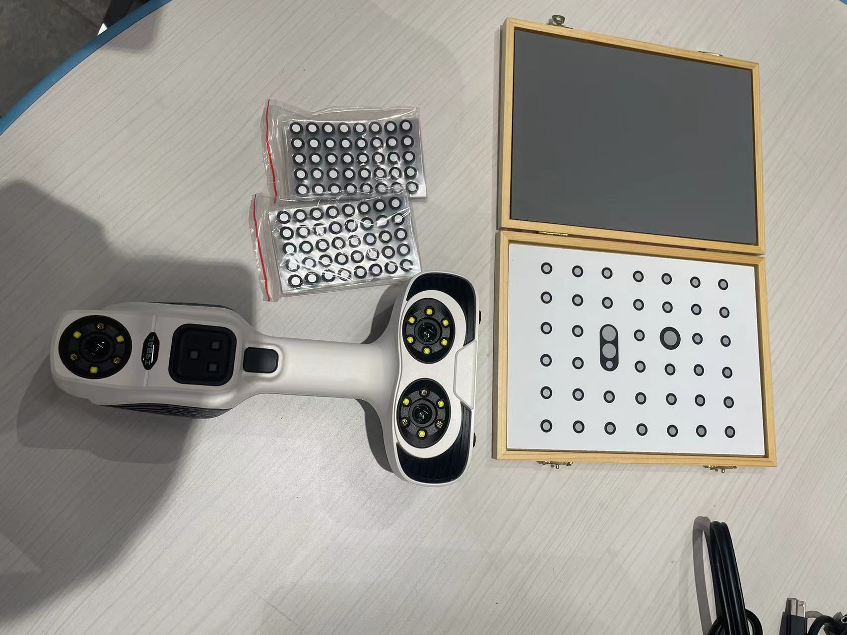
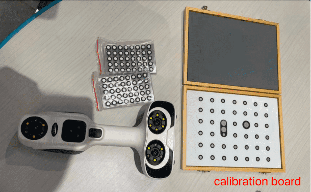
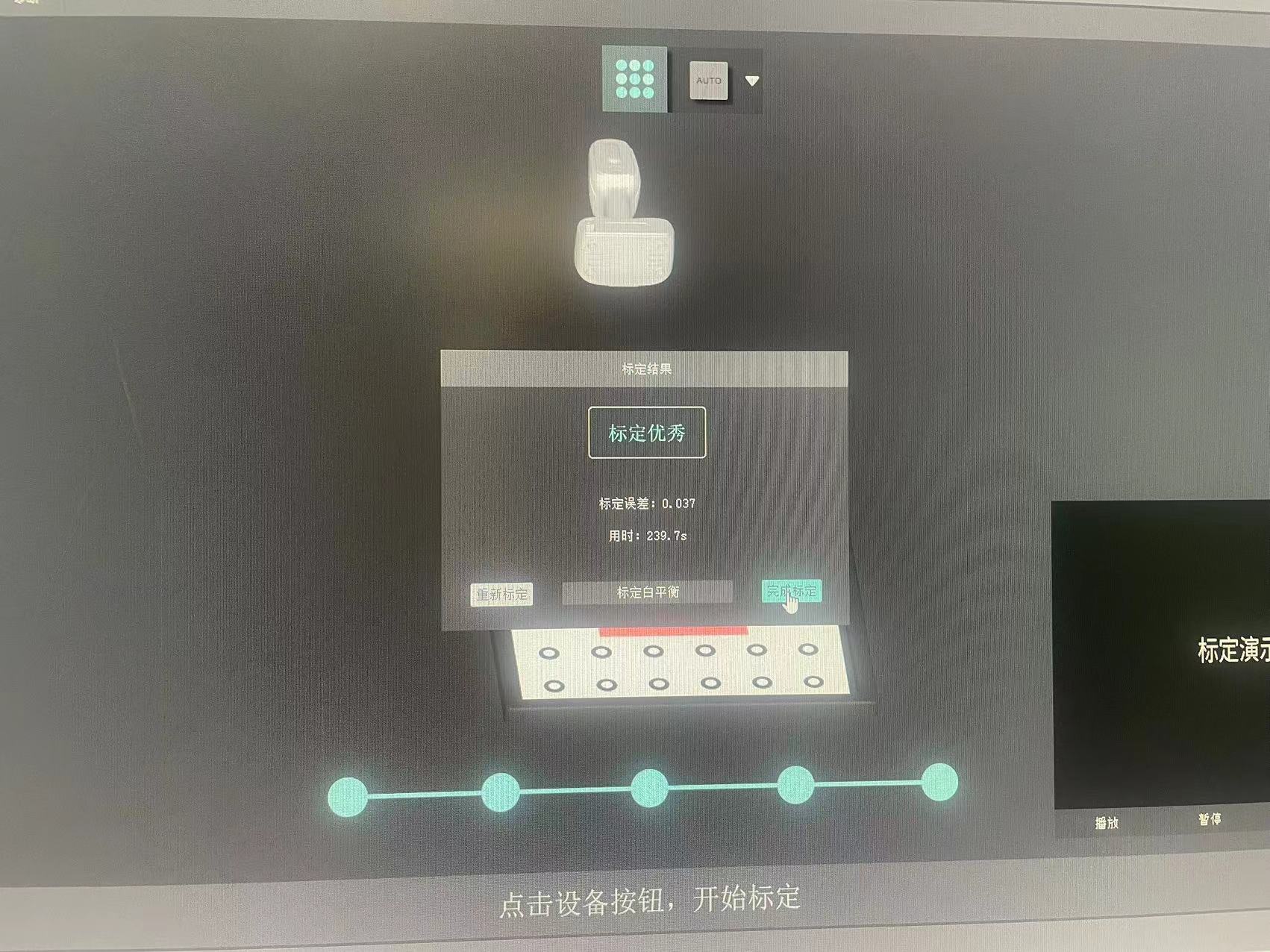
Step 3: Perform Calibration with iReal E2
Prepare the calibration board and the iReal E2 and follow the gesture demonstrated in the software to do the clibaration for all angles
Adjust different angles and distances with the object and start scanning. If the software shows blue, it means the scan area is good
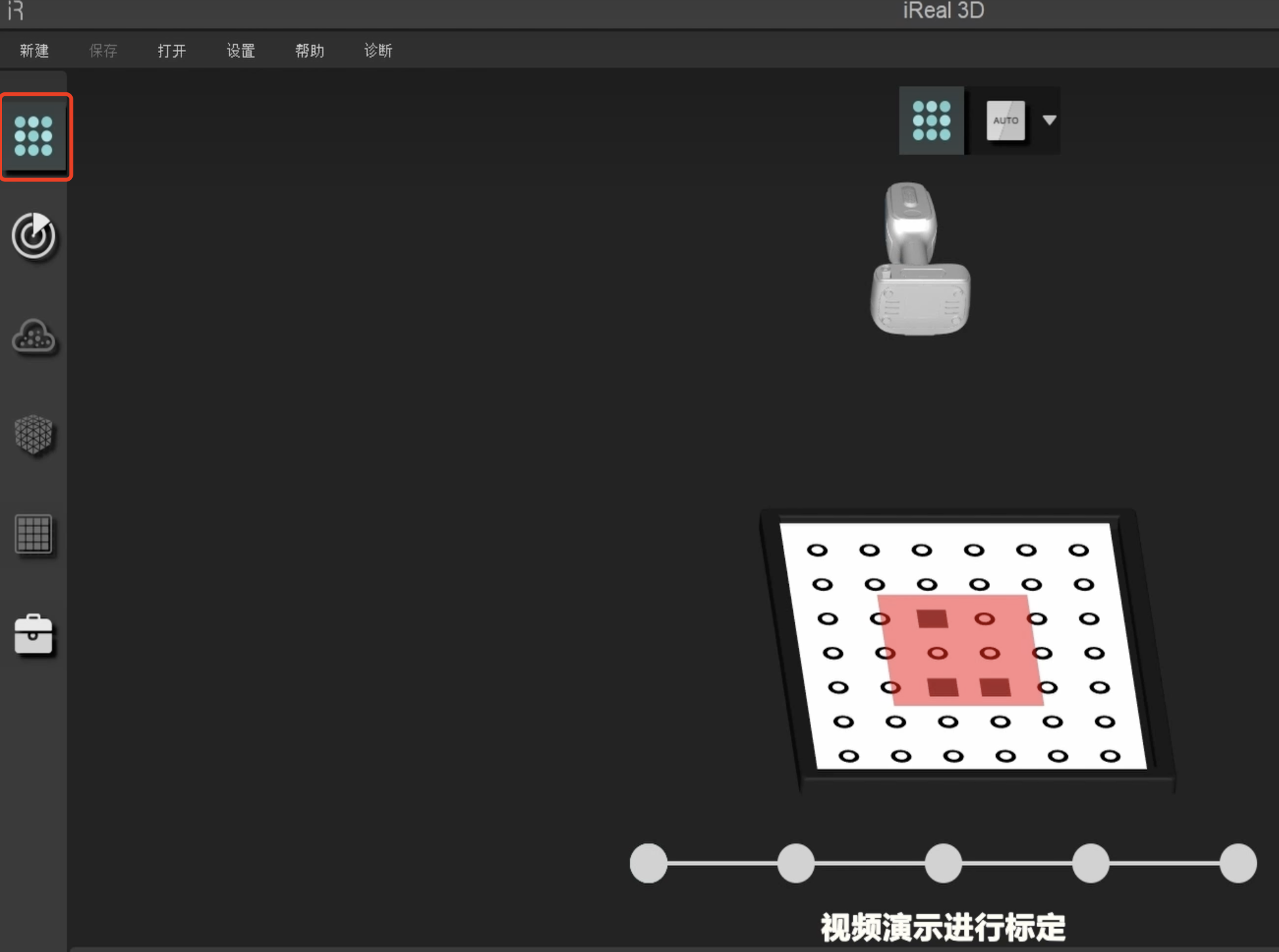
You can perform the calibration for different angles multiple times until you achieve following output
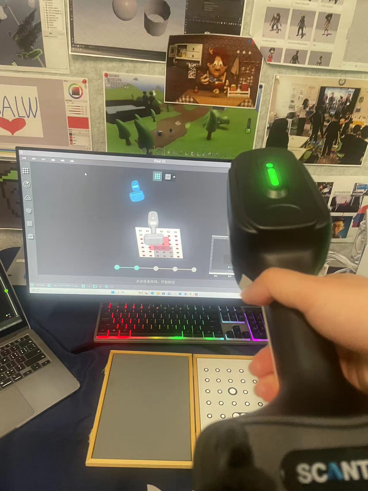
Step 4: Start scanning with iReal E2
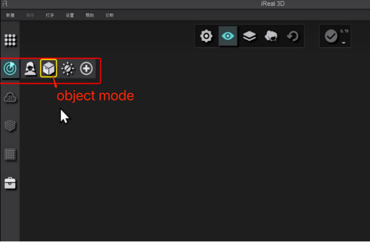
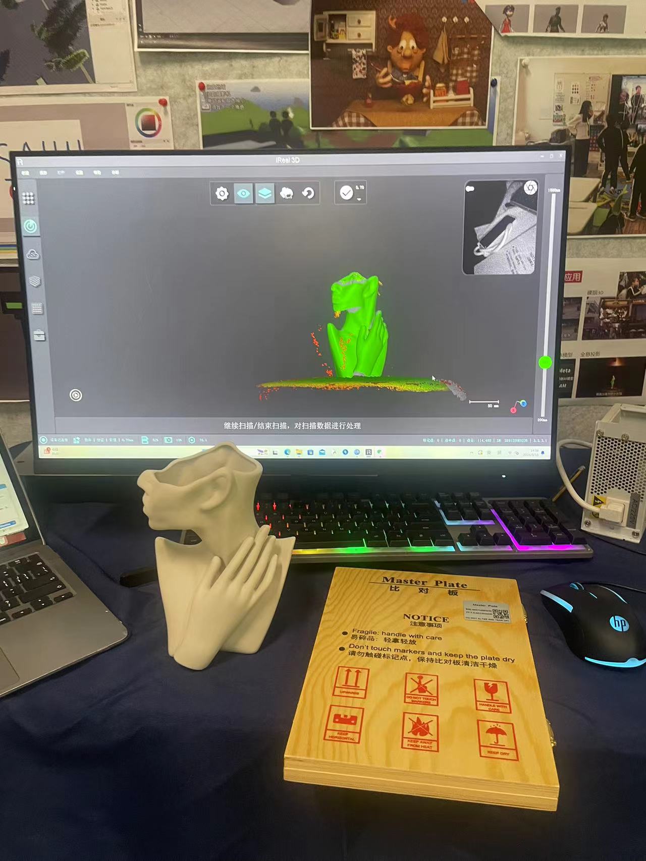
First choose the object mode, since I choose to scan a vase
My partner Dion is performing the scanning
I am performing the scanning
You can see in the video that if you have some parts scanned without right distance or angle, it will mark the area red,
but all you need to do is to scan the same area again with right angle and distance.
Finally, the resulting image captures most of the details, but there are still some minor details missing and some extra parts could be removed later.
Step 5: Fix the missing details
The iReal system can automatically fill in any missing details or gaps that were not fully captured during the scanning process following steps as below:
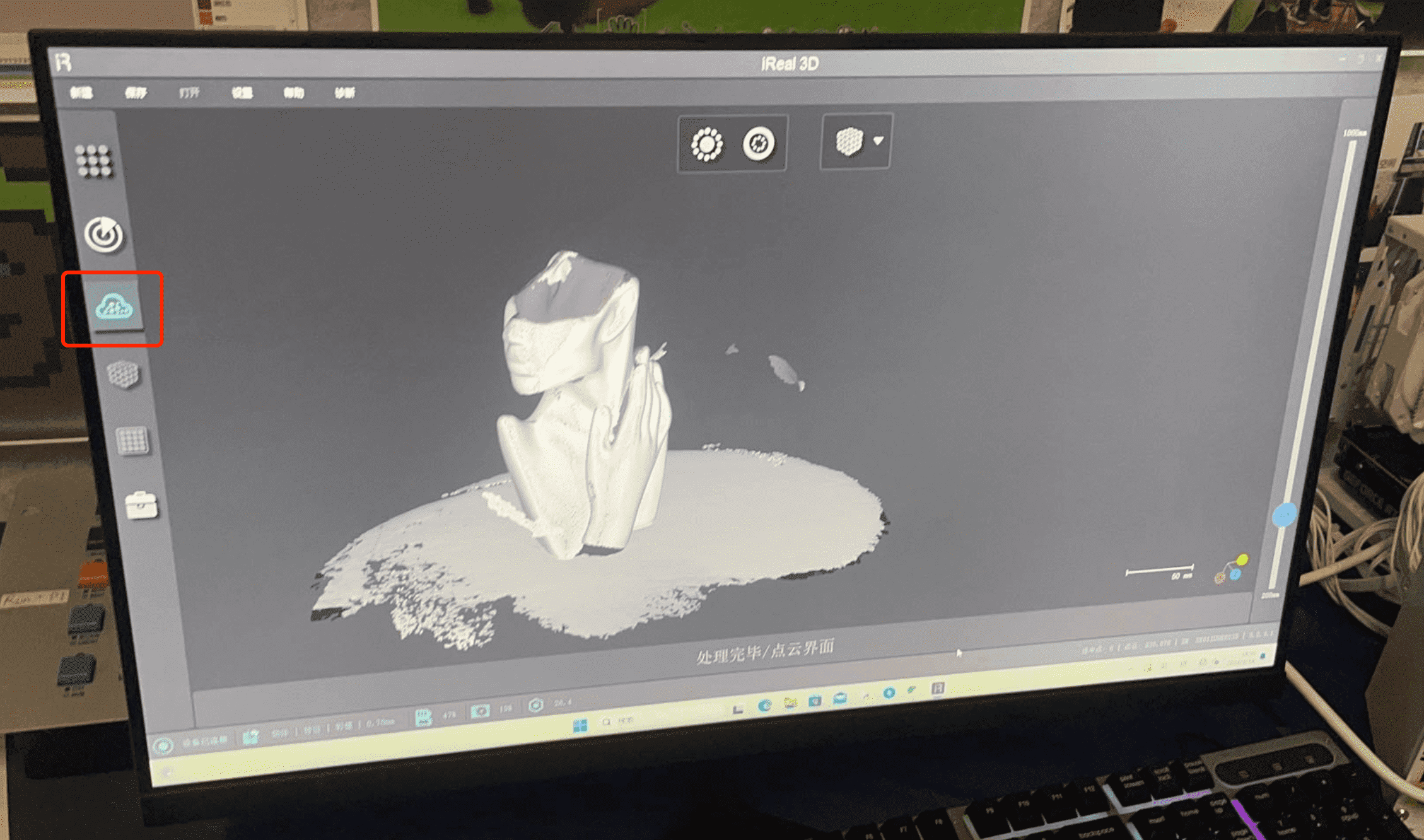
First, you need to upload all the scanned data to the cloud storage of iReal by clicking on the button on the left side.
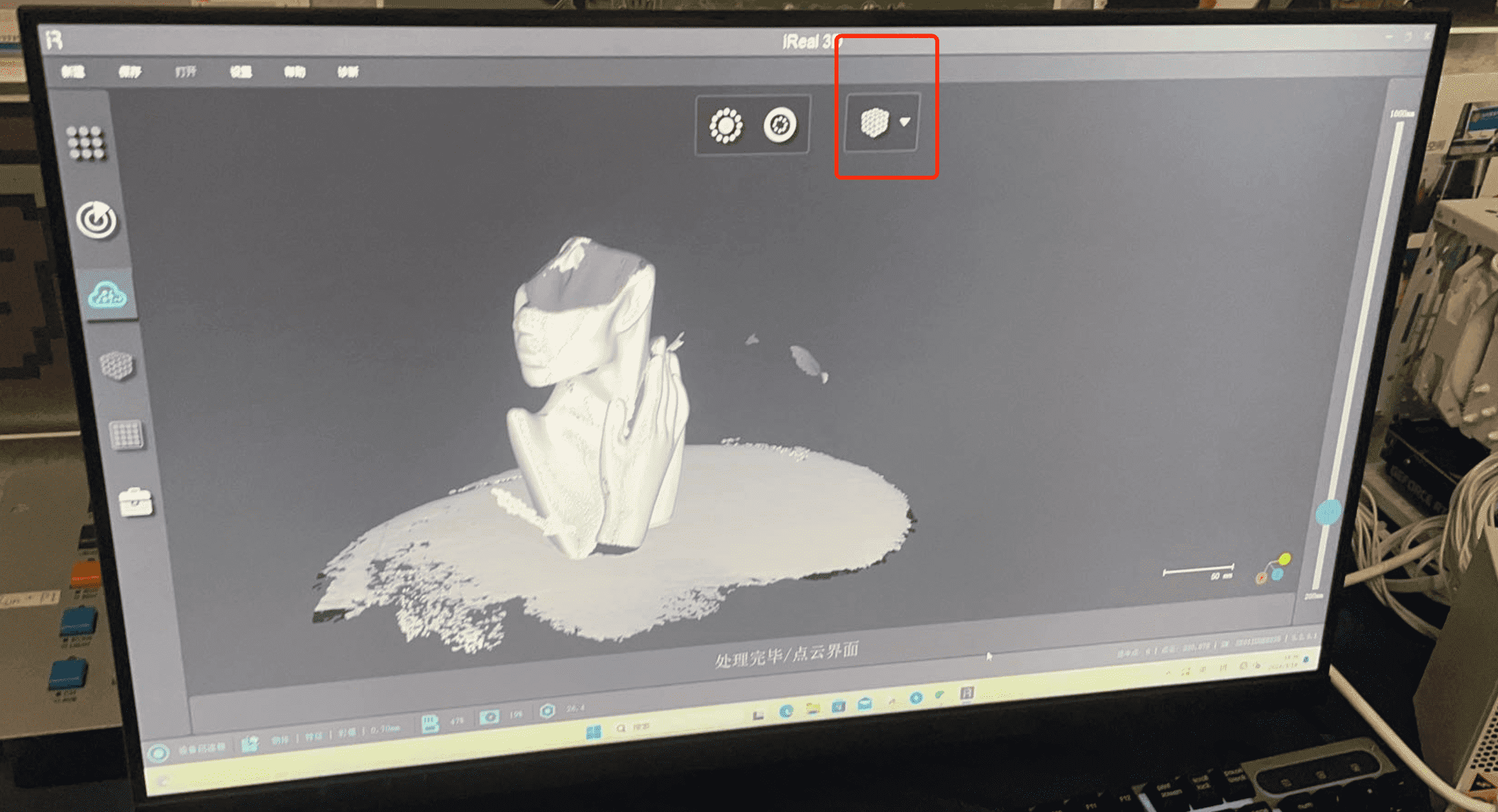
Then click the “mesh optimization” button on the bottom
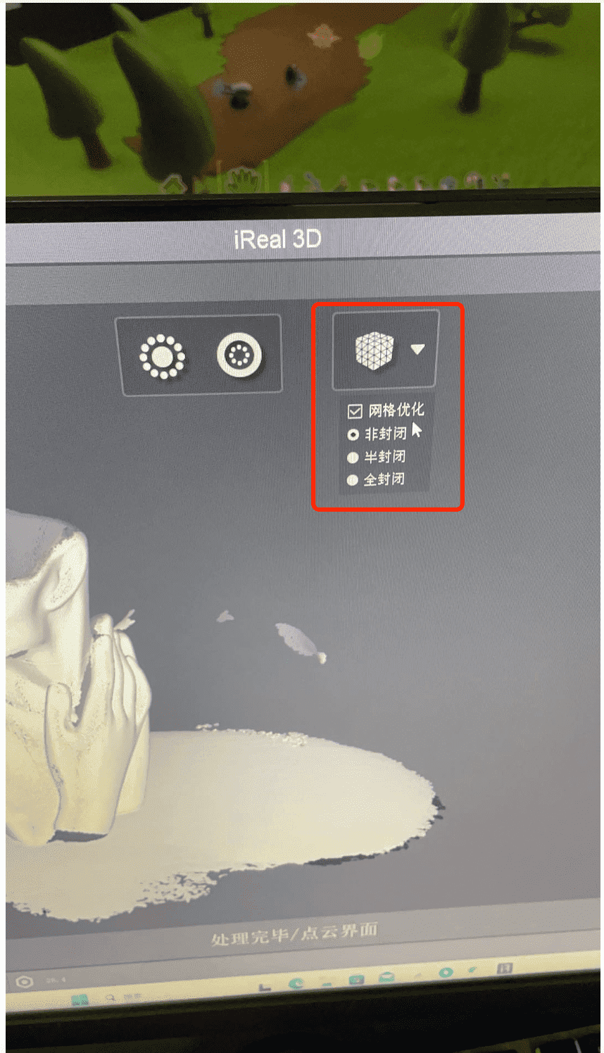
Finally, the iReal will automatically fixed all the missing details or gaps.