Weekly assignments
- week 1. Project Management
- week 2. Computer Aided Design
- week 3. Computer Controlled Cutting
- week 4. Electronics Production
- week 5. 3D Scanning and Printing
- week 6. Embeded Programming
- week 7. Computer Controlled Machining
- week 8. Electronics Design
- week 9. Output Devices
- week 10. Mechanical design & Machine Design
- week 11. Break & Midterm Review
- week 12. Input devices
- week 13. Moulding and Casting
- week 14. Networking and communications
- week 15. Interface and application programming
- week 16. Wildcard Week
- week 17. Applications And implications
- week 18. Project Development
- week 19. Invention, Intellectual Property and Income
Week16. Wildcard Week
Individual assignment:
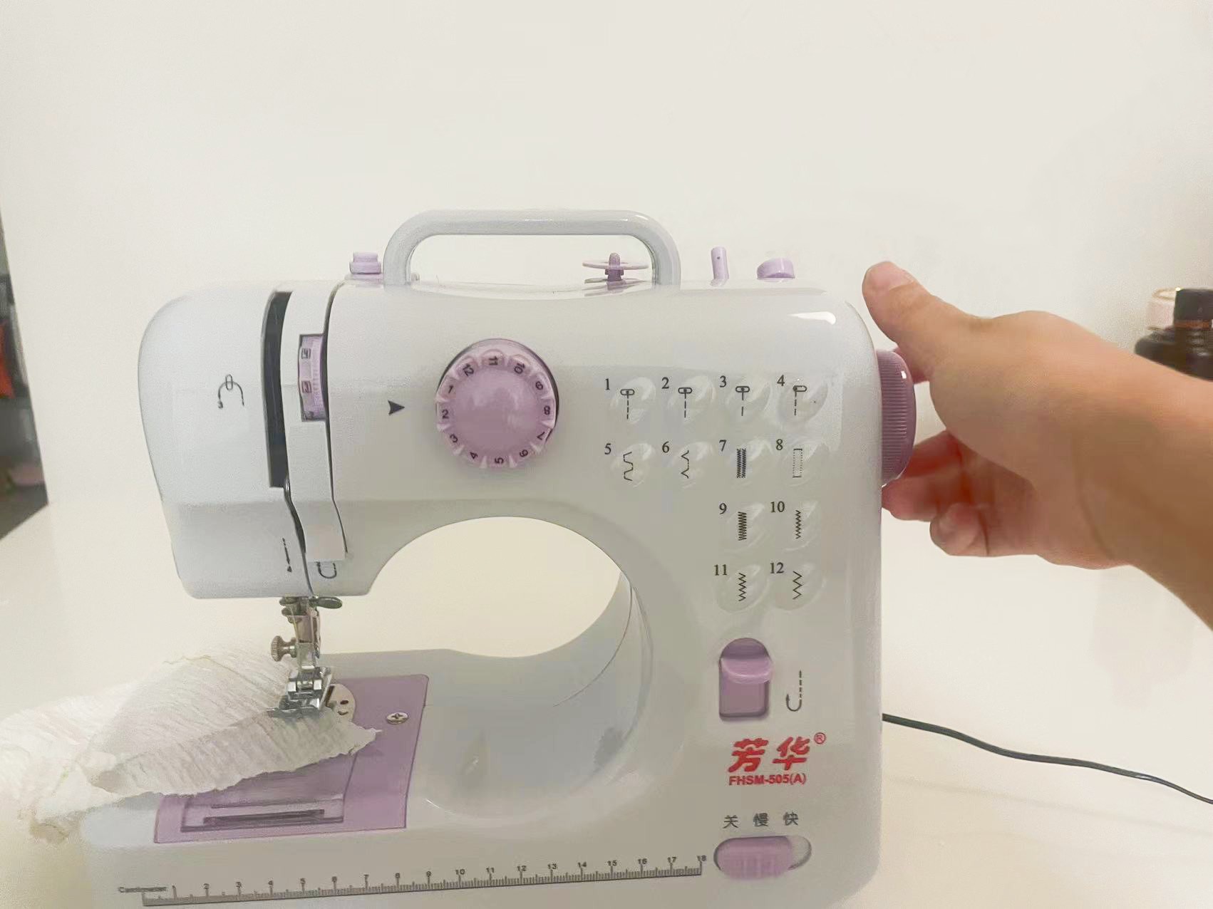
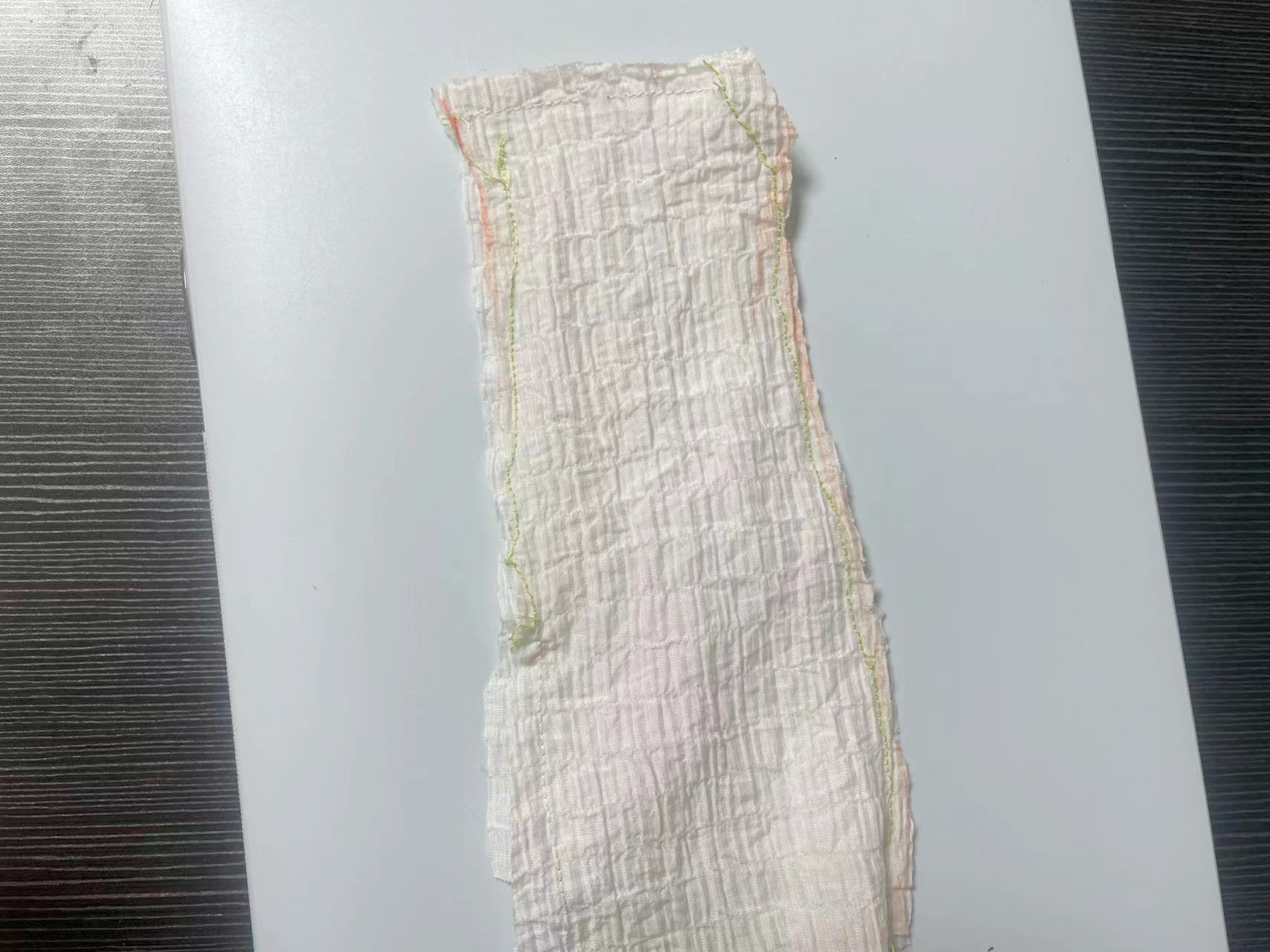
Assigment1 Sewing
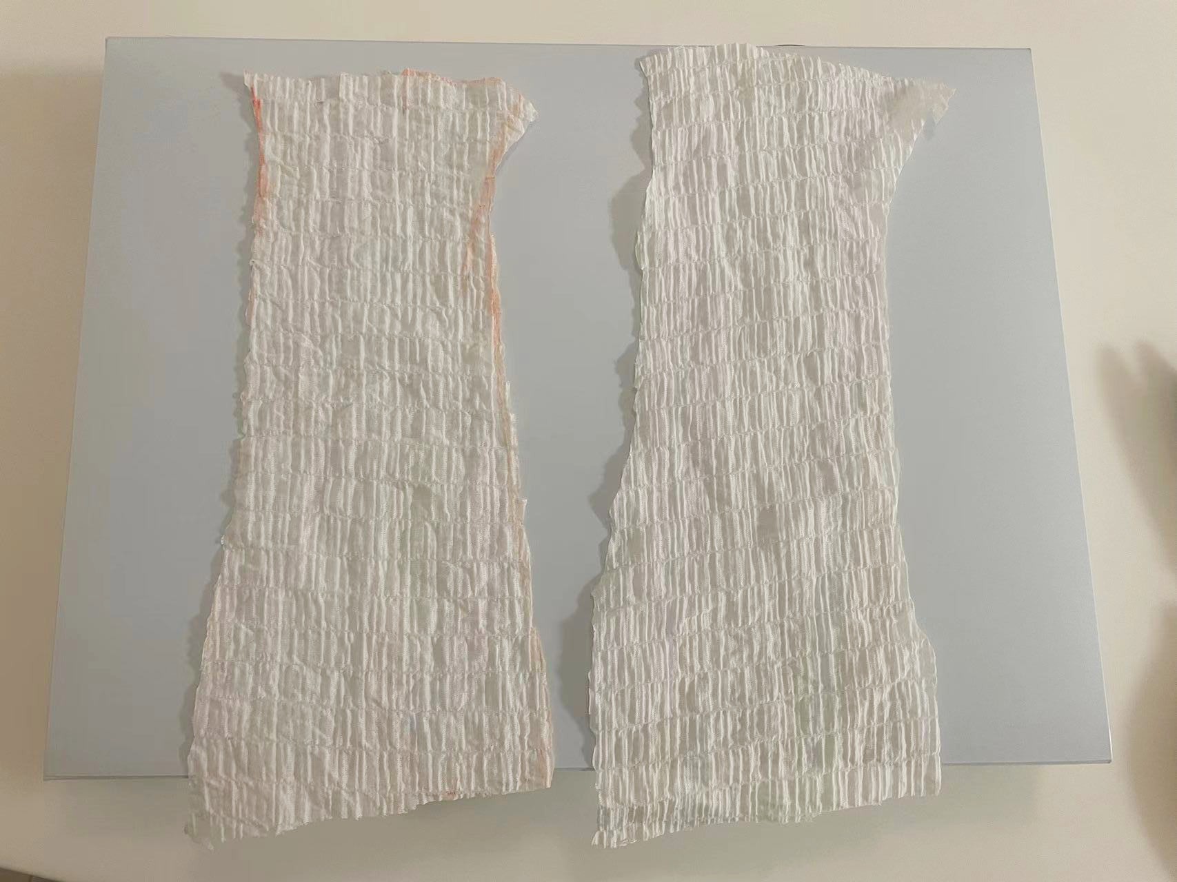
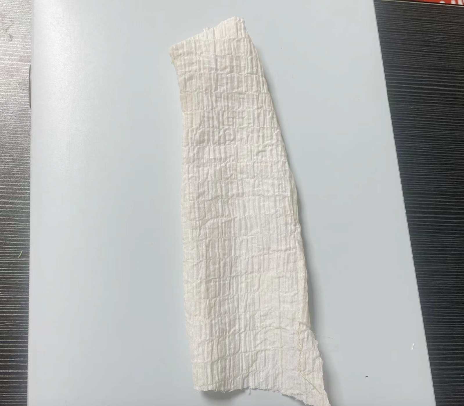
Step1. Cutting the fabric


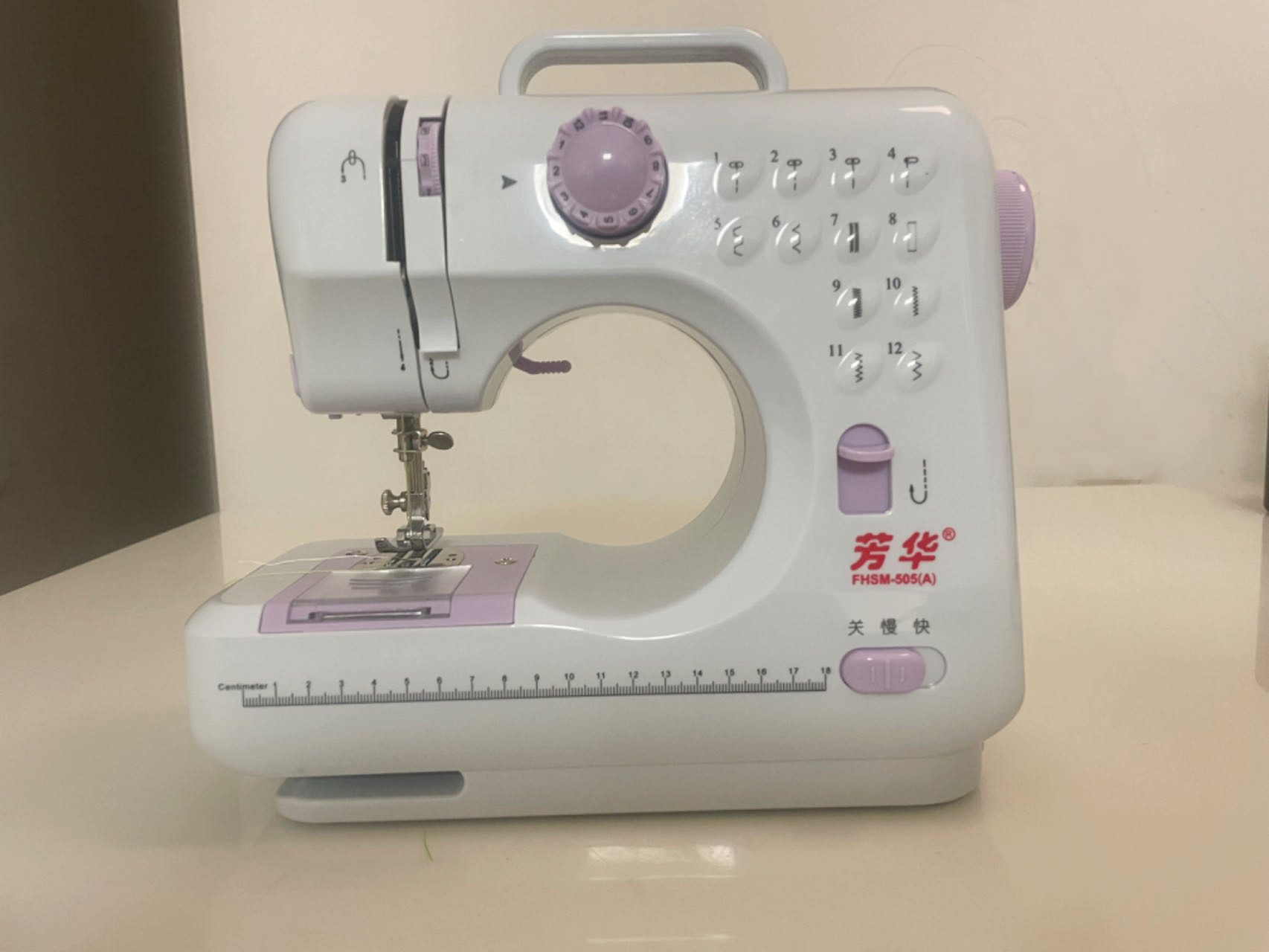
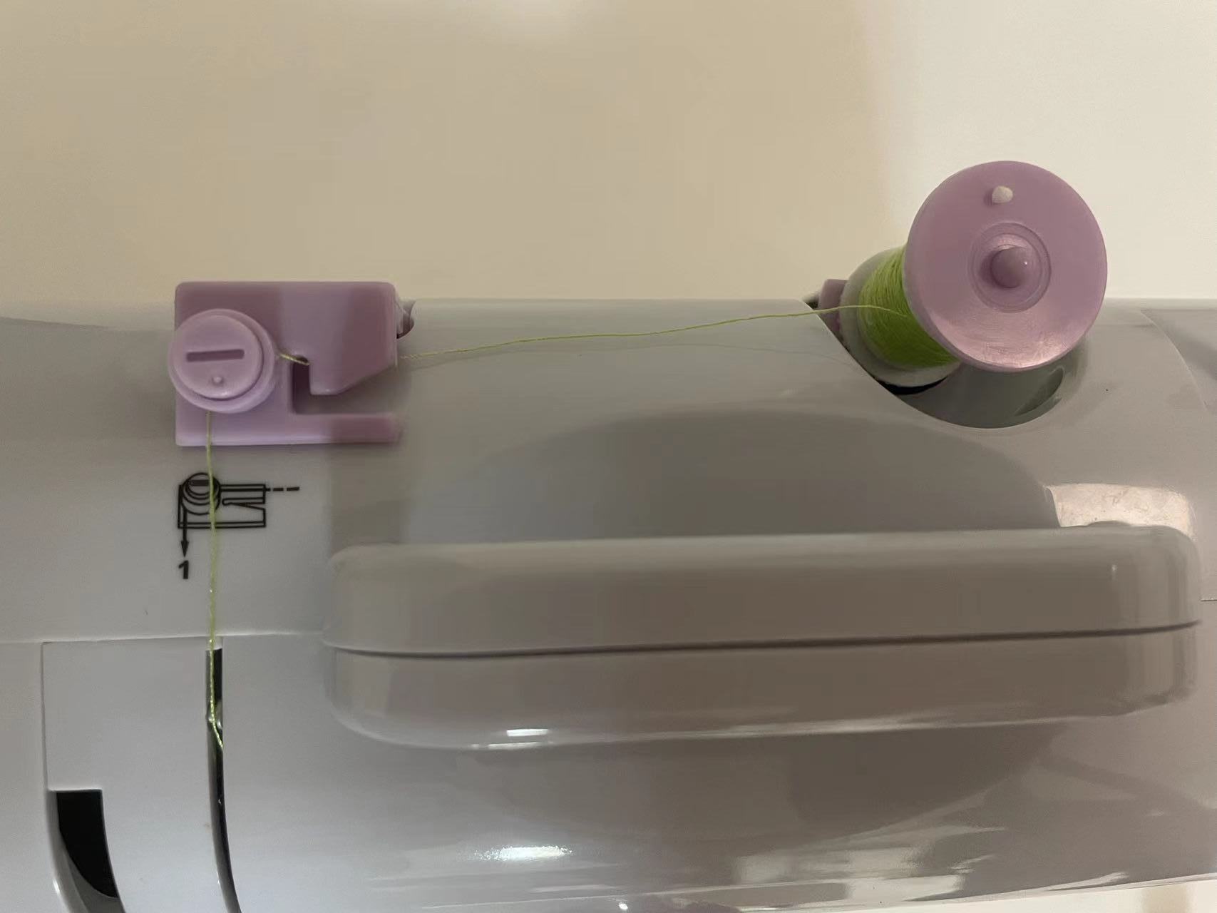
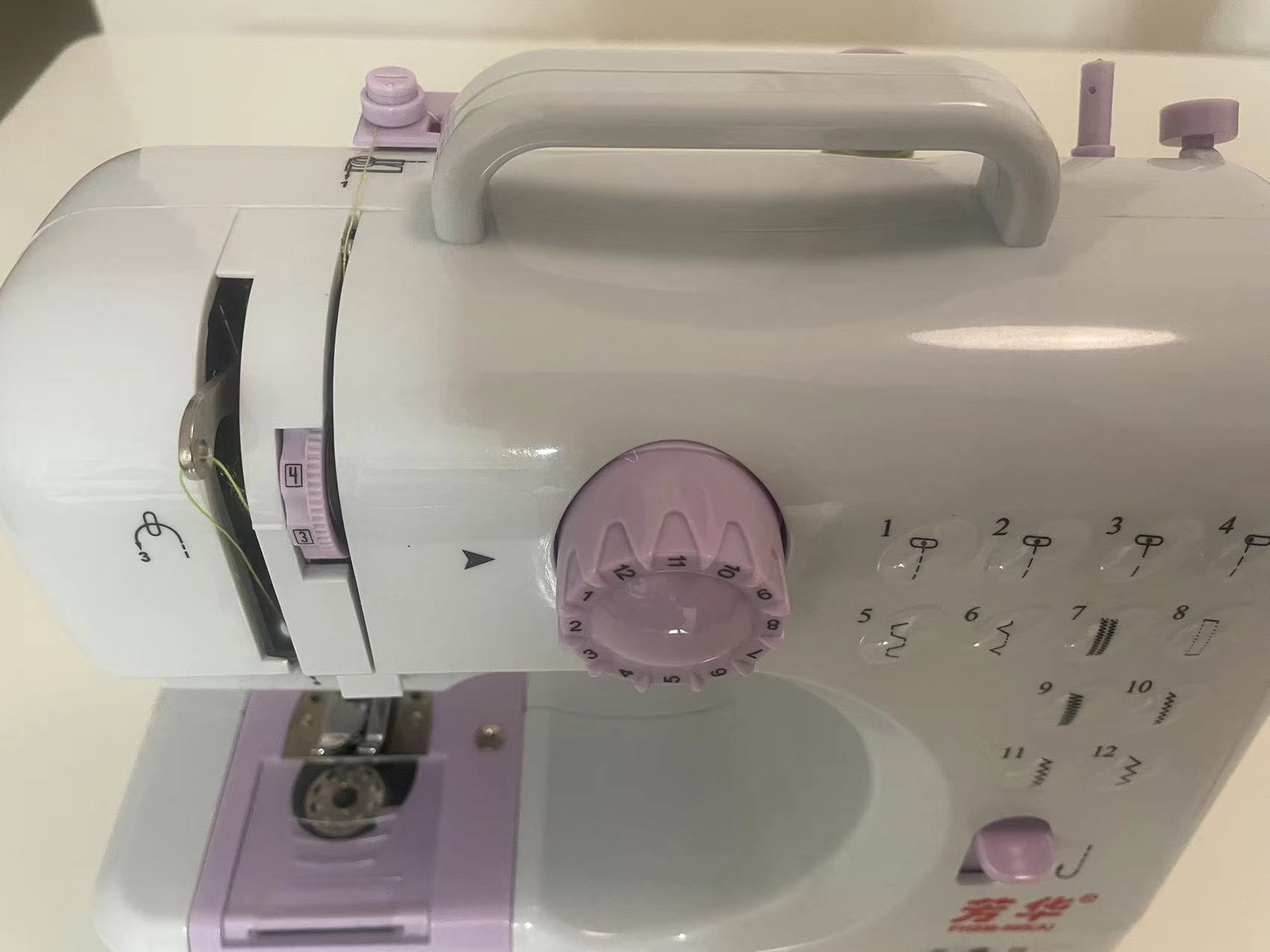
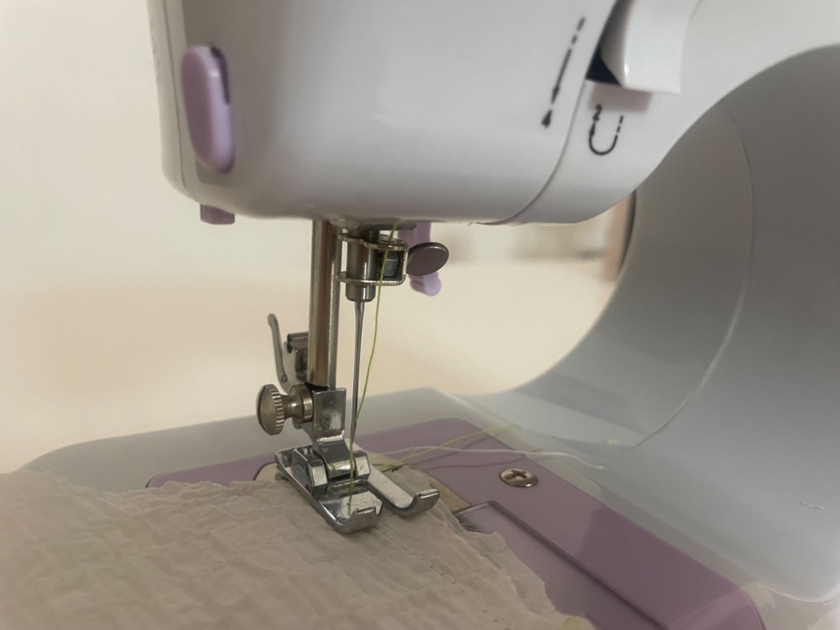
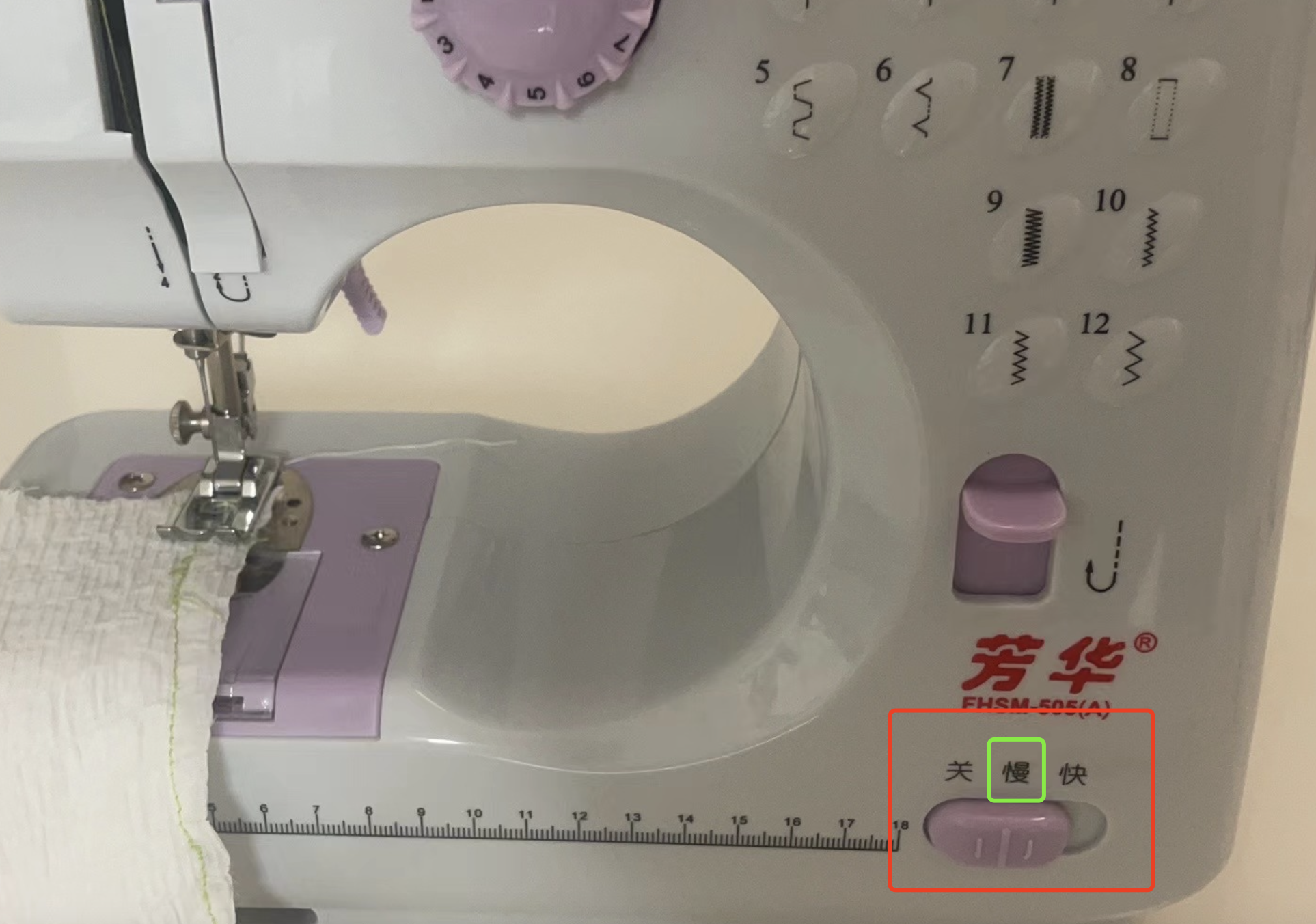
Step2. Prepare the sewing machine
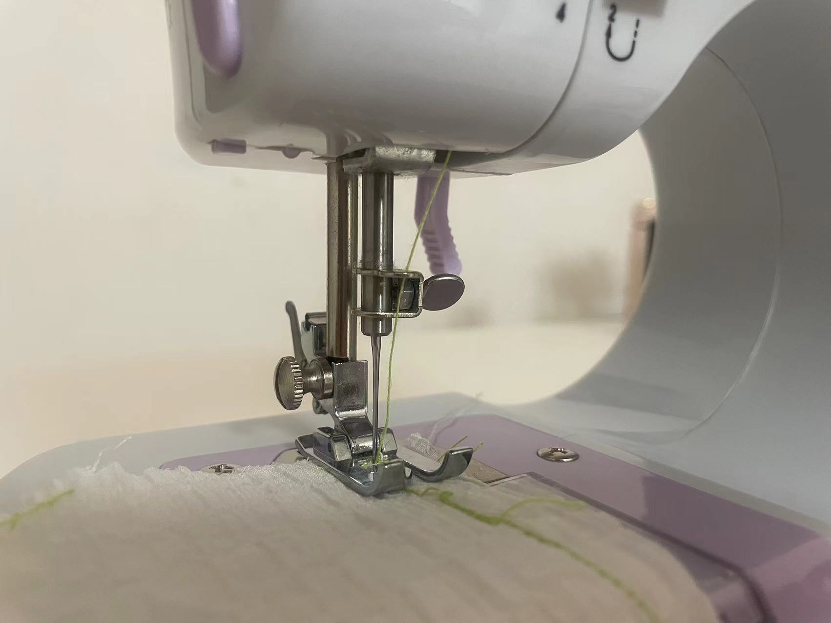
2.1 Thread the machine.
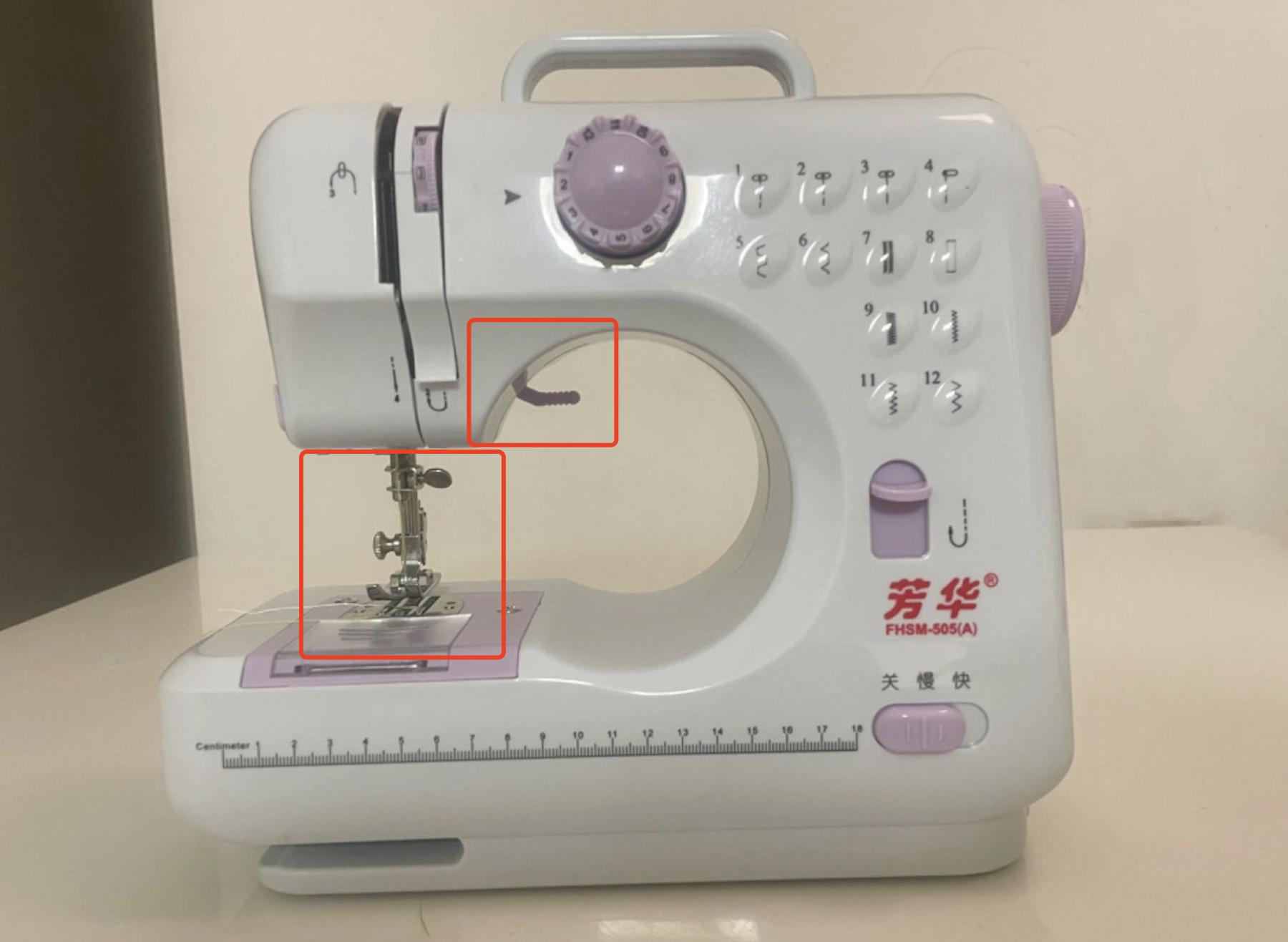
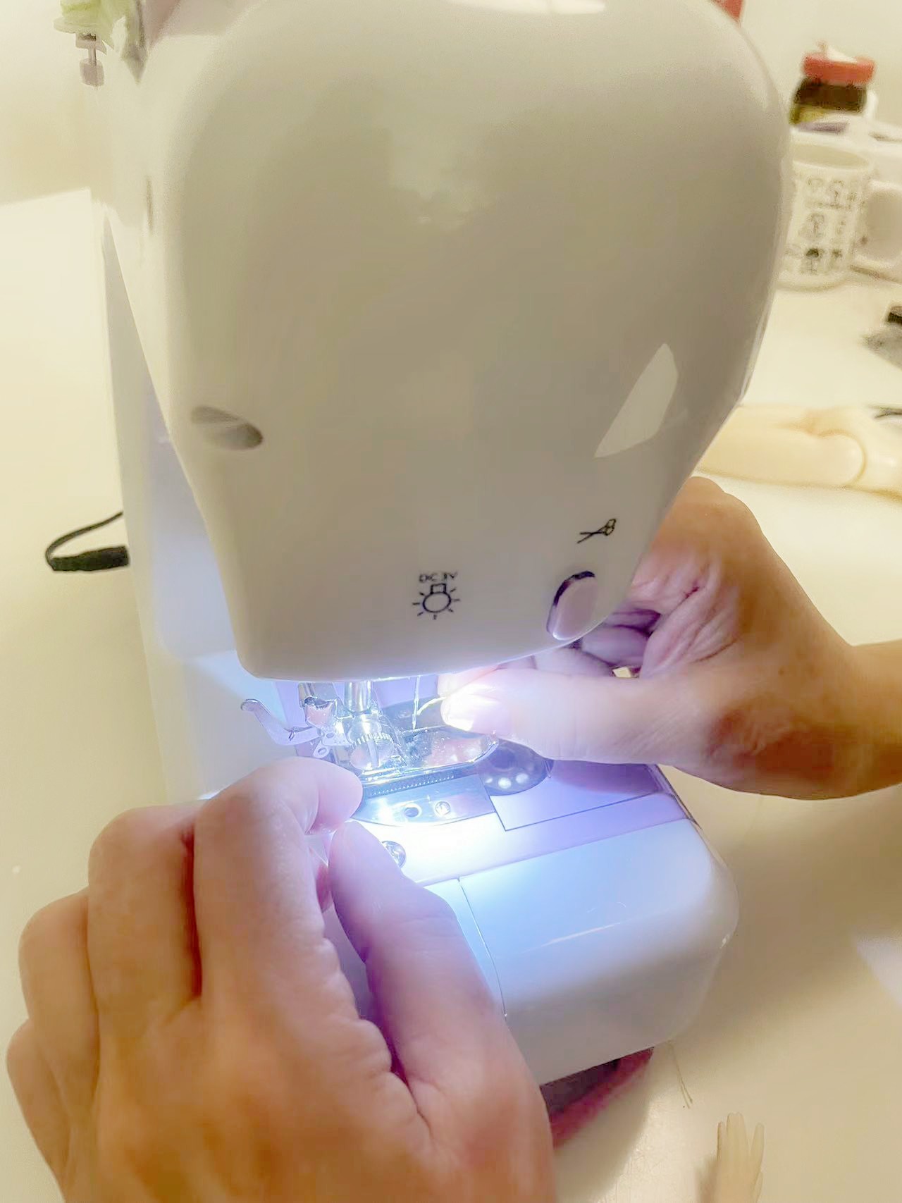
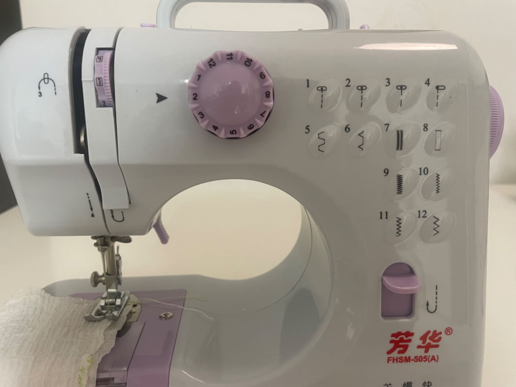
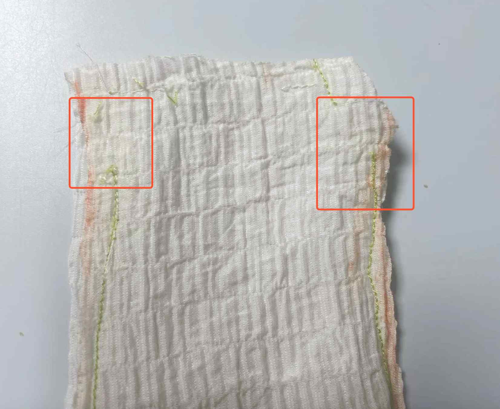
2.2 Start to sew.
2.3 Post-sewing processing

Assigment2 Research TINY Machine Learning
Part1. Machine Learning and TinyML
Focus on TinyML
Advantages of TinyML
Applications of TinyML
Benefits of TinyML
Conclusion
Part2. Introduction about Edge Impulse
Part3. Introduction about seeed Xiao nRF52840 sense
Features :
- Powerful wireless capabilities: Bluetooth 5.0 with onboard antenna
- Powerful CPU: Nordic nRF52840, ARM® Cortex®-M4 32-bit processor with FPU, 64 MHz
- Ultra-Low Power: Standby power consumption is less than 5μA
- Battery charging chip: Supports lithium battery charge and discharge management
- Onboard 2 MB flash
- Onboard PDM microphone (only in Seeed Studio XIAO nRF52840 Sense)
- Onboard 6-axis LSM6DS3TR-C IMU (only in Seeed Studio XIAO nRF52840 Sense)
- Ultra Small Size: 20 x 17.5mm, Seeed Studio XIAO series classic form-factor for wearable devices
- Rich interfaces: 1xUART, 1xI2C, 1xSPI, 1xNFC, 1xSWD, 11xGPIO(PWM), 6xADC
- Single-sided components, surface mounting design
Implementation of My Assigment
Part1. Start to learn tiny machine learning
Part2. Use Edge Impulse to do Machine Learning
Step 1.Installation of Edge Impulse
-1. Create an Edge Impulse account.
-2. Install Python 3 on your host computer.
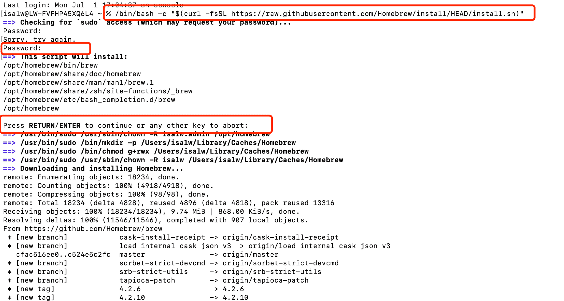
-3. Install Node.js v18 or higher on your host computer. Alternatively, run the following commands(For MAC):
/bin/bash -c "$(curl -fsSL https://raw.githubusercontent.com/Homebrew/install/HEAD/install.sh)"
brew install node
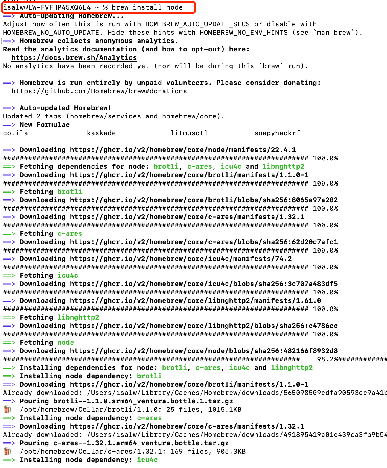
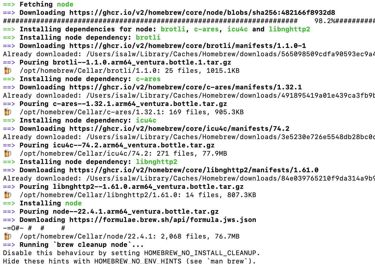
Run "node v-" to check the node version, it should be above v18
brew install node

Now verify the node installation directory: npm config get prefix If it returns /usr/local/, run the following commands to change npm's default directory:
                   mkdir ~/.npm-global
                   npm config set prefix '~/.npm-global'
                   echo 'export PATH=~/.npm-global/bin:$PATH' >> ~/.profile

               mkdir ~/.npm-global
               npm config set prefix '~/.npm-global'
               echo 'export PATH=~/.npm-global/bin:$PATH' >> ~/.zprofile
Install the CLI tools
npm install -g edge-impulse-cli
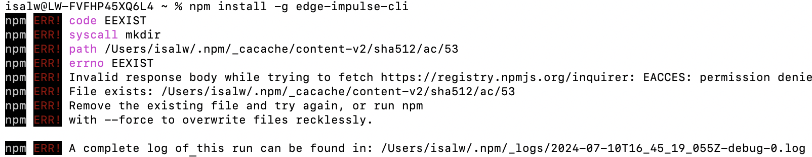
Now the Edge Impulse is successfully set up.
Step 2.Prepare the nRF52840 sense
The installation of nRF52840 sense can refer to my week9 assignment.
First to prepare the nRF52840 to properly obtain all the accelerometers' data.
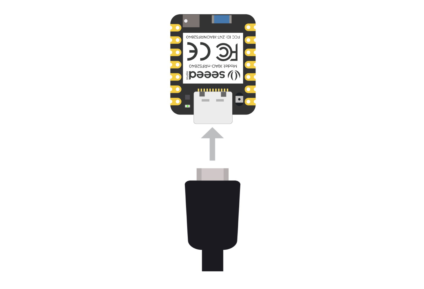
1. Connect the Seeed Studio XIAO nRF52840 Sense to your computer via a USB Type-C cable.
2. Upload ReadXIAOAccelerometer.ino sketch.
      // XIAO BLE Sense LSM6DS3 Data  Forwarder

      #include "LSM6DS3.h"
      #include "Wire.h"

     //Create a instance of class LSM6DS3
     LSM6DS3 myIMU(I2C_MODE, 0x6A);  //I2C device address 0x6A

     #define CONVERT_G_TO_MS2 9.80665f
     #define FREQUENCY_HZ 50
     #define INTERVAL_MS (1000 / (FREQUENCY_HZ + 1))

     static unsigned long last_interval_ms = 0;
     void setup(){
        Serial.begin(115200);
        while (!Serial){

         if (myIMU.begin() != 0) {
            Serial.println("Device error");
         } else {
            Serial.println("Device OK!");
         }
      }
     }
     void loop() {
        if (millis() > last_interval_ms + INTERVAL_MS) {
          last_interval_ms = millis();
          Serial.print(myIMU.readFloatAccelX() * CONVERT_G_TO_MS2, 4);
          Serial.print('\t');
        Serial.print(myIMU.readFloatAccelY() * CONVERT_G_TO_MS2, 4);
        Serial.print('\t');
        Serial.println(myIMU.readFloatAccelZ() * CONVERT_G_TO_MS2, 4);
     }
   }
2. Upload the above code to your XIAO Sense and open the serial monitor or serial ploter to see the accelerometer data.
Just move the nRF52840 microprocessor randomly after open the Serial monitor or Serial plotter.
Step 3. Connect to Edge impulse and Forward Accelerometer data
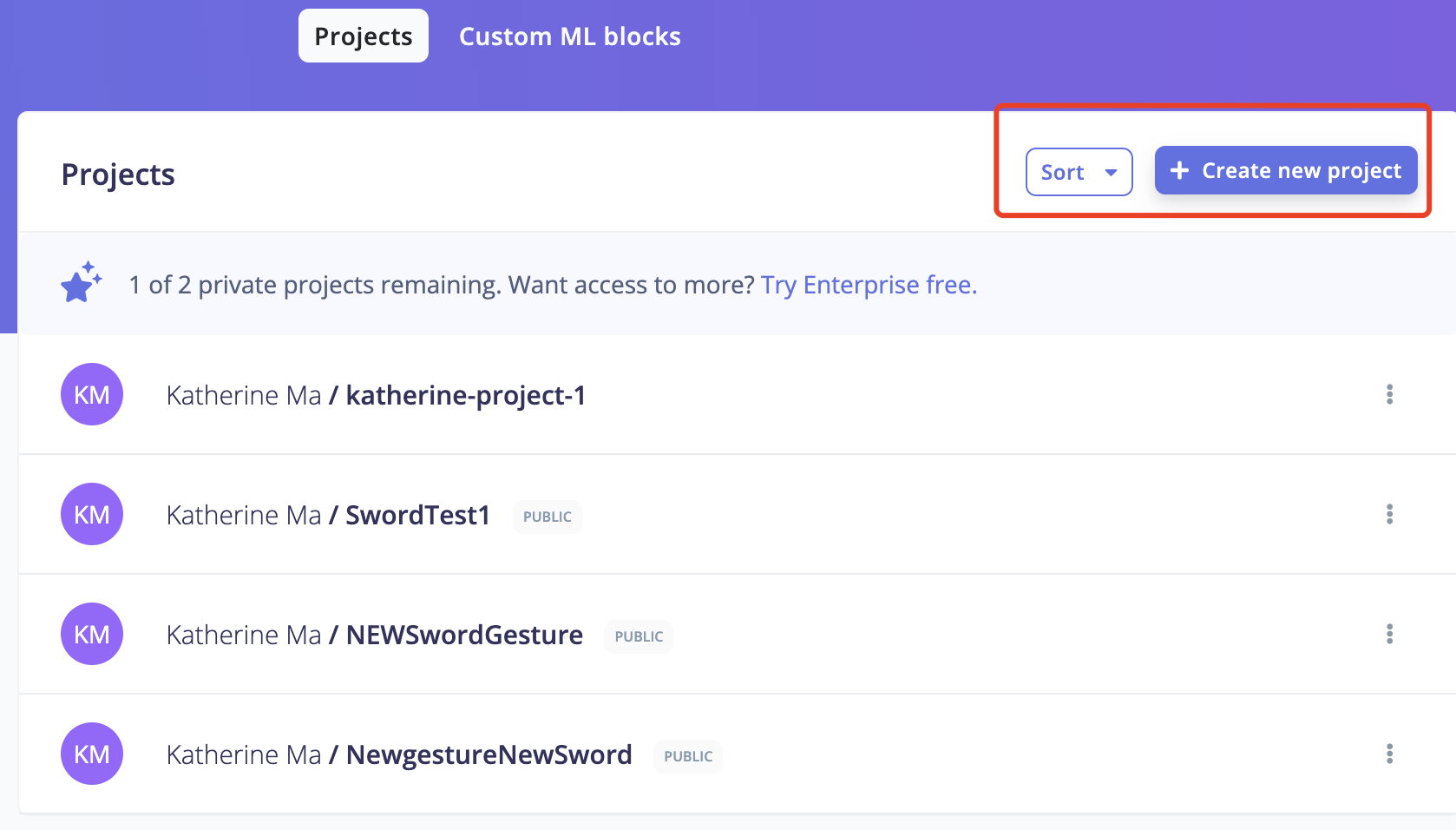
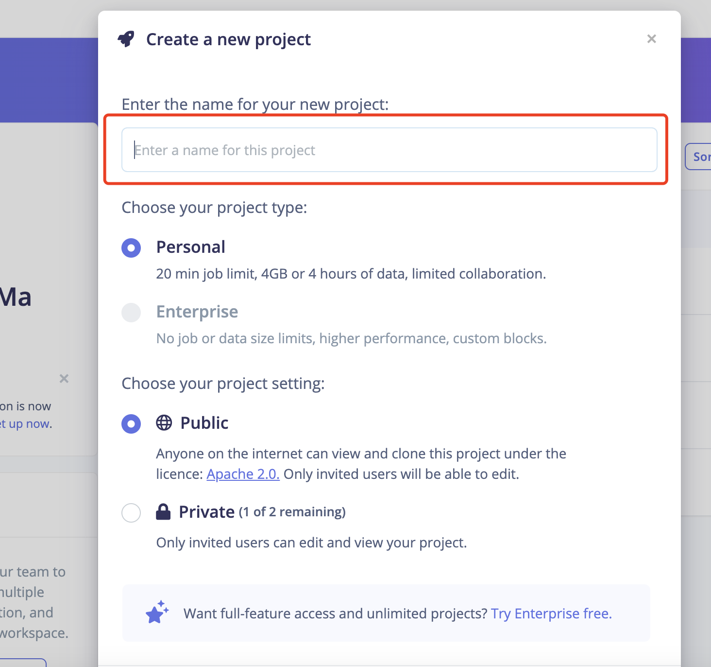
1: Create an Edge Impulse project.
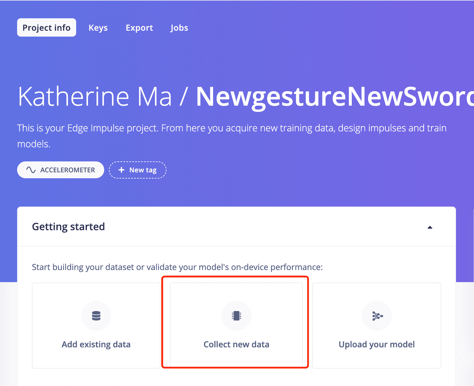
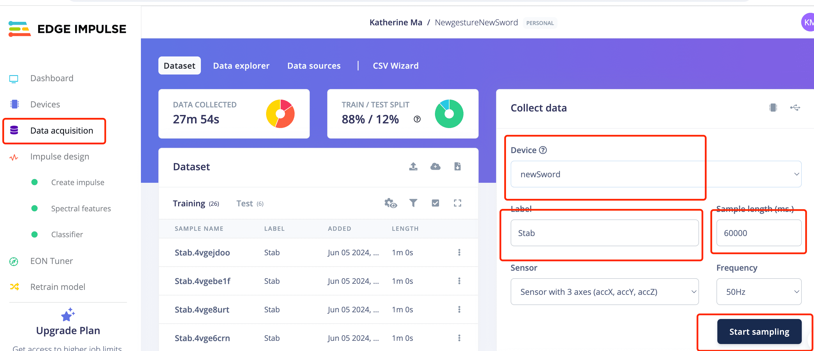
2: Open your project and start to collect data.
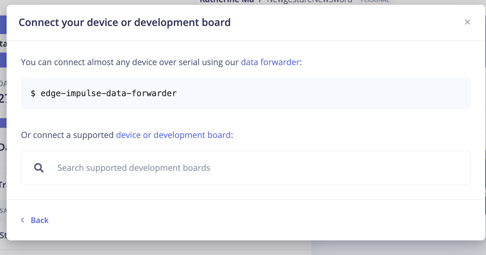
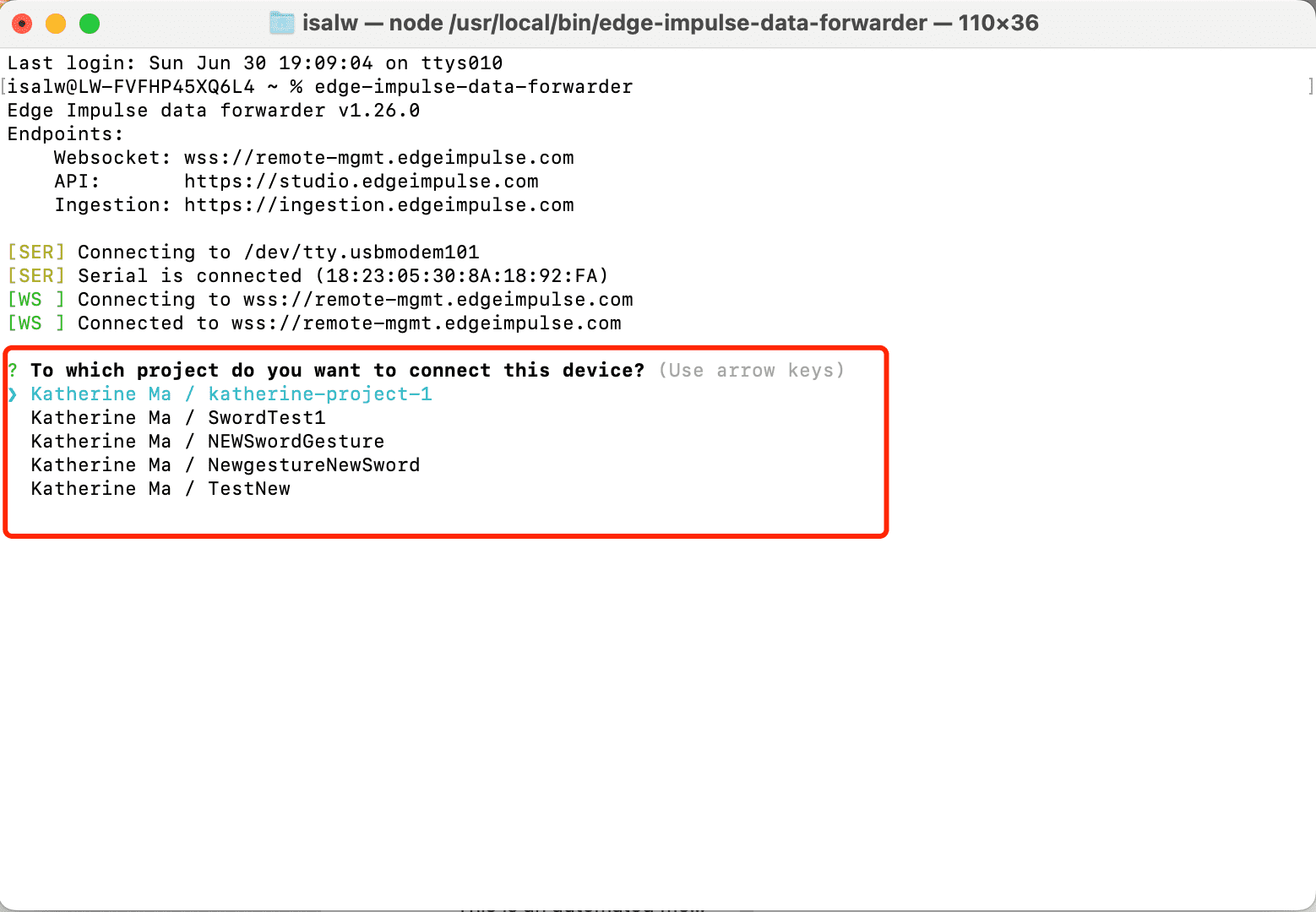
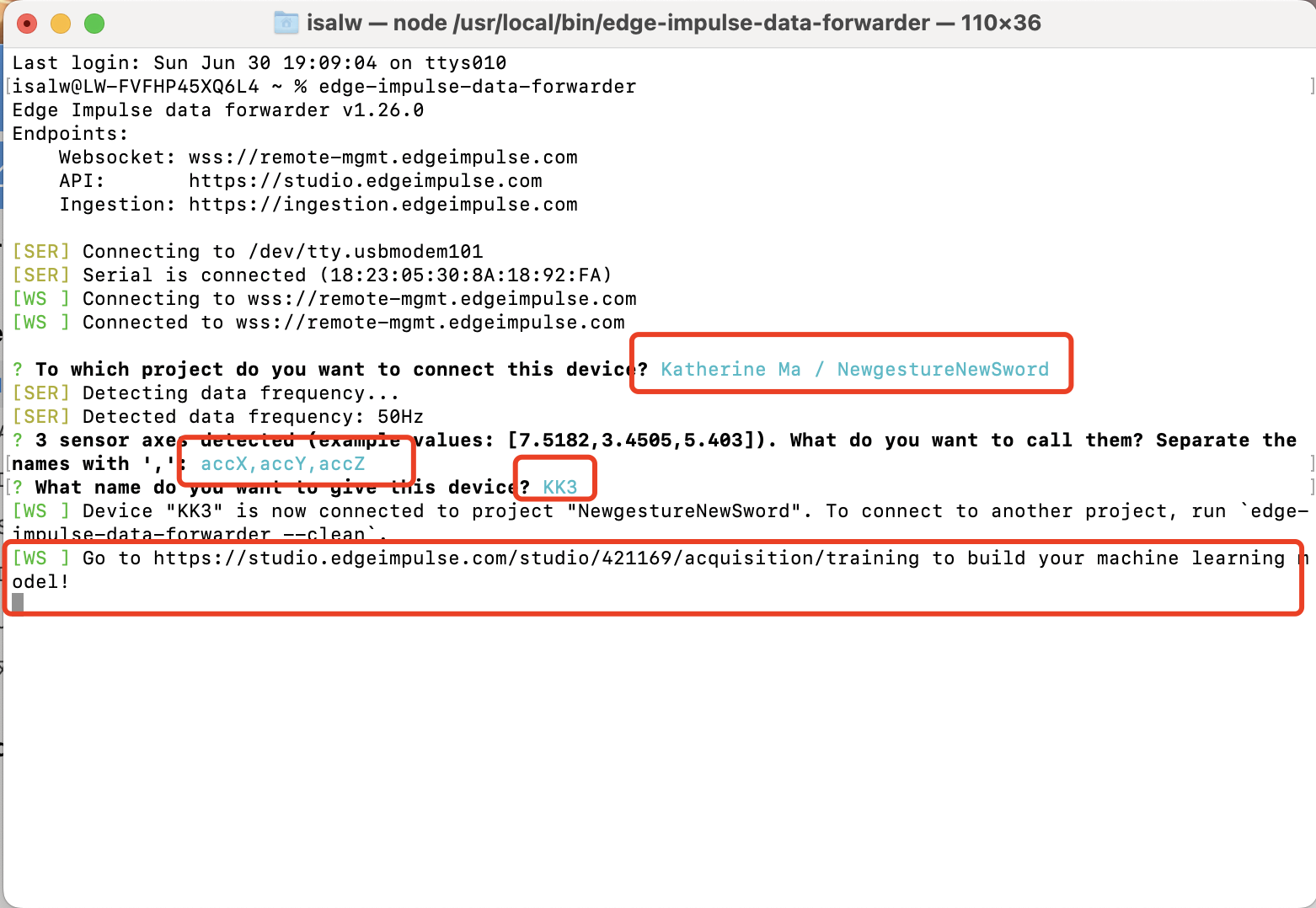
3: Open the termial and start follow the forwarder steps.
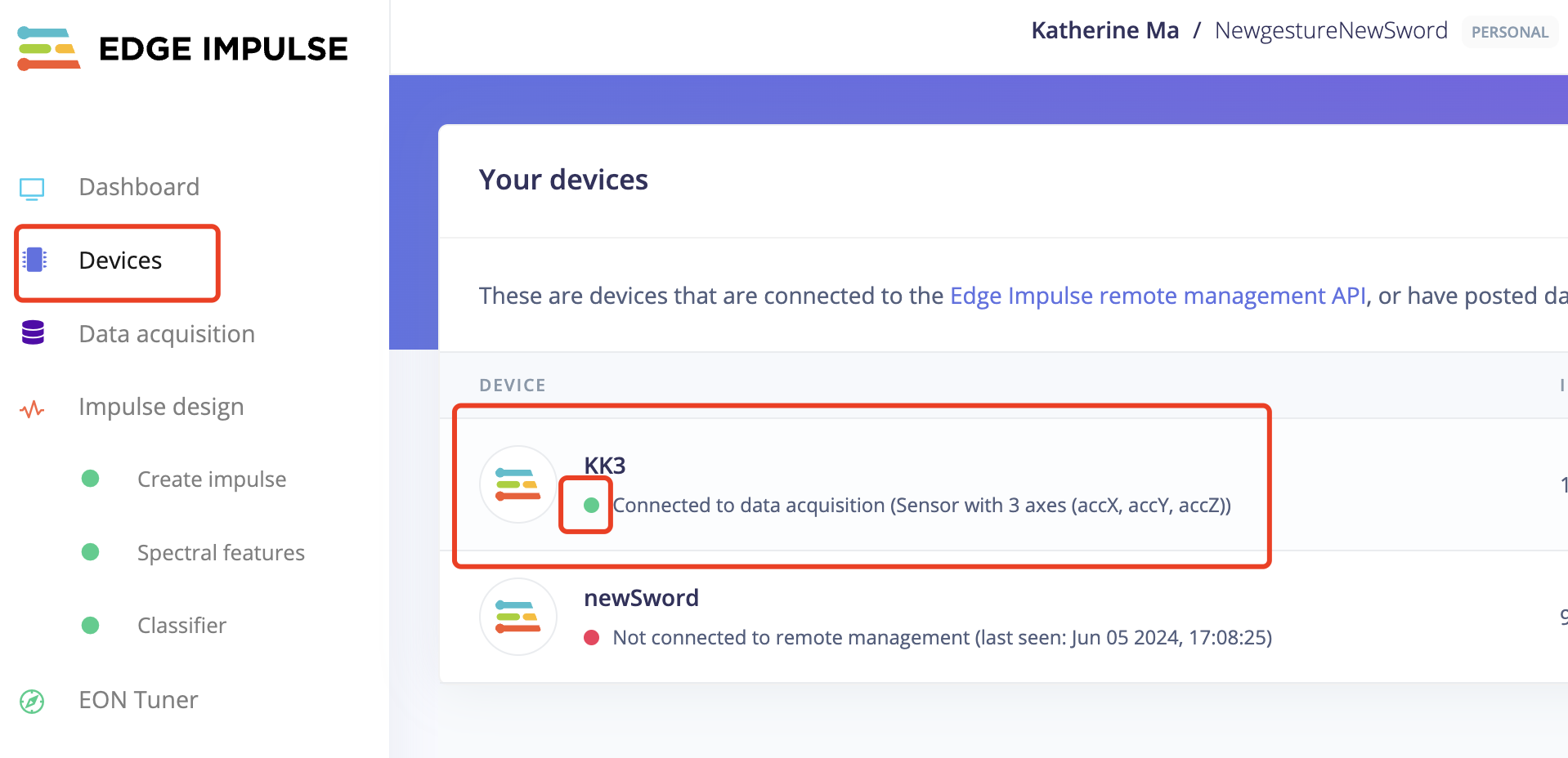
4: Go back to Edge Impluse and Start to train data!
3: Open the termial and start follow the forwarder steps.
4: Go back to Edge Impluse and Start to train data!
When you start to train data:
- Change the label name to be the gesture you are training
- Change the "sample time" to the duration of your training session. You can set it to be longer. During this period, repeat the same action repeatedly.
I have created two projects to train two sets of gestures.
The first project's movement are simple only idle, UpDown and stab.
4.1 Stab gesture for the first sword
4.2 TakeItUp gesture for the first sword
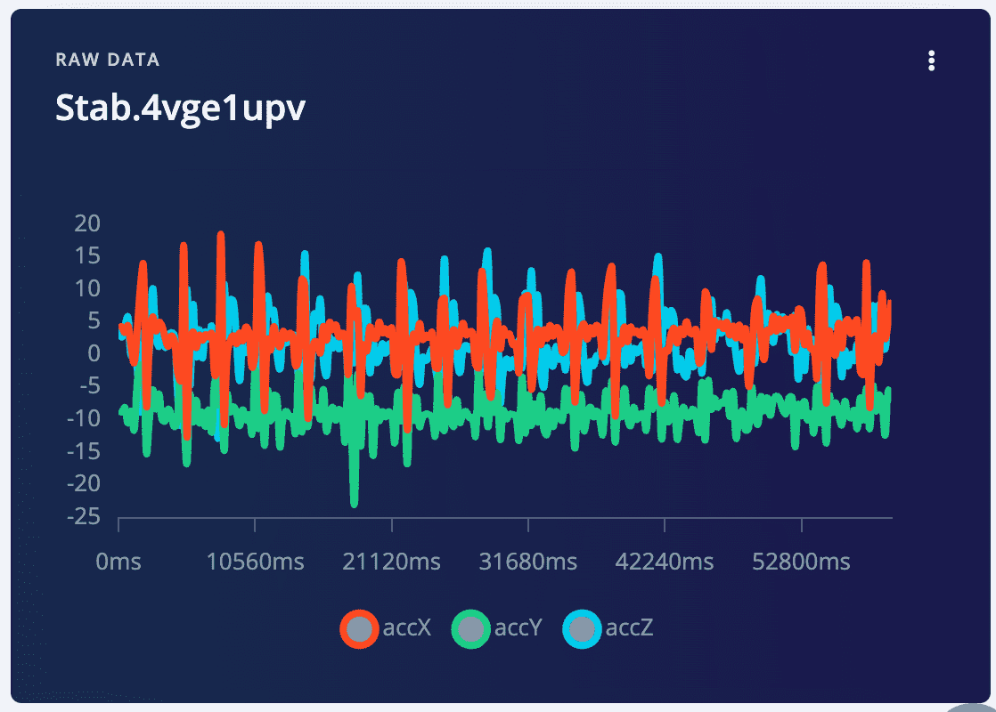
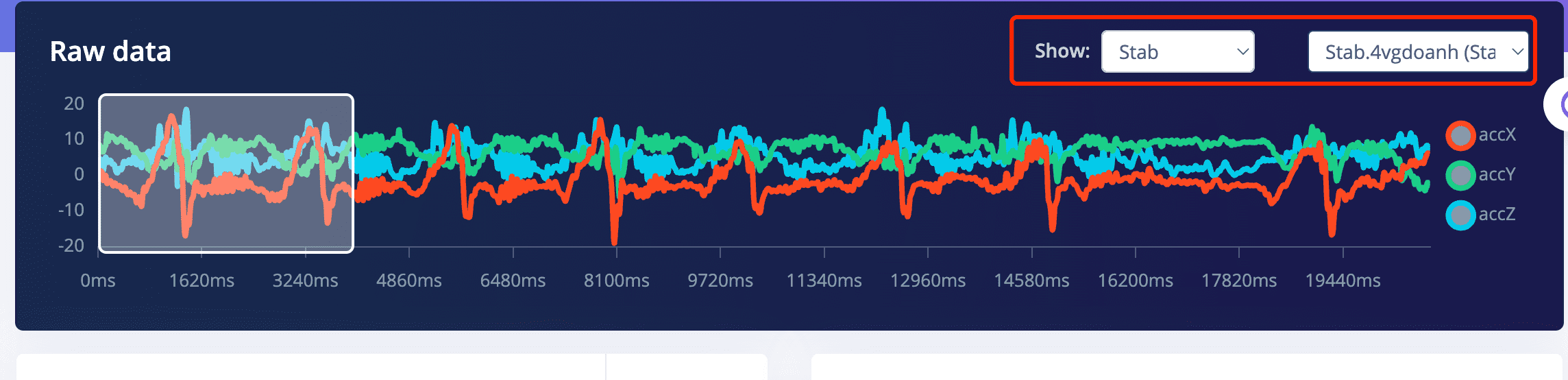
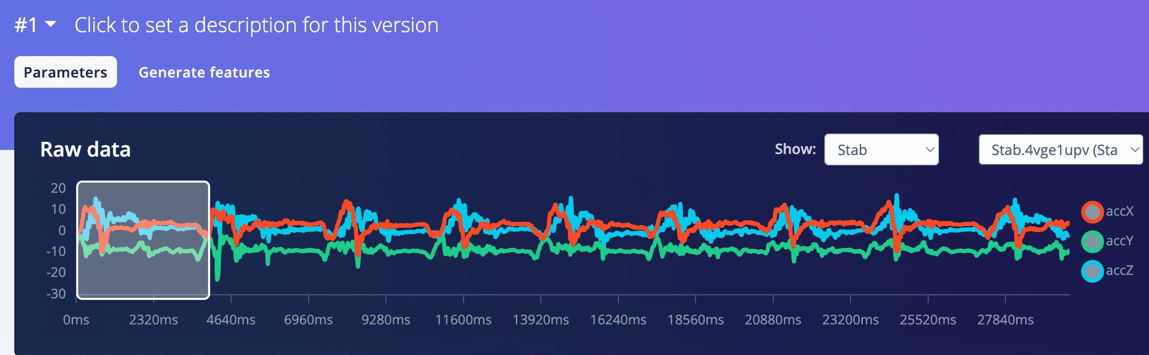
4.3 Stab gesture for the new sword
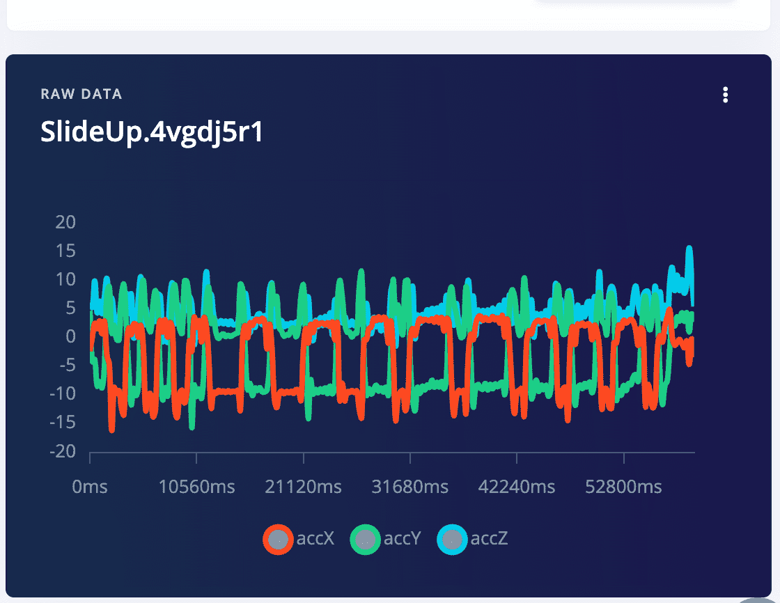
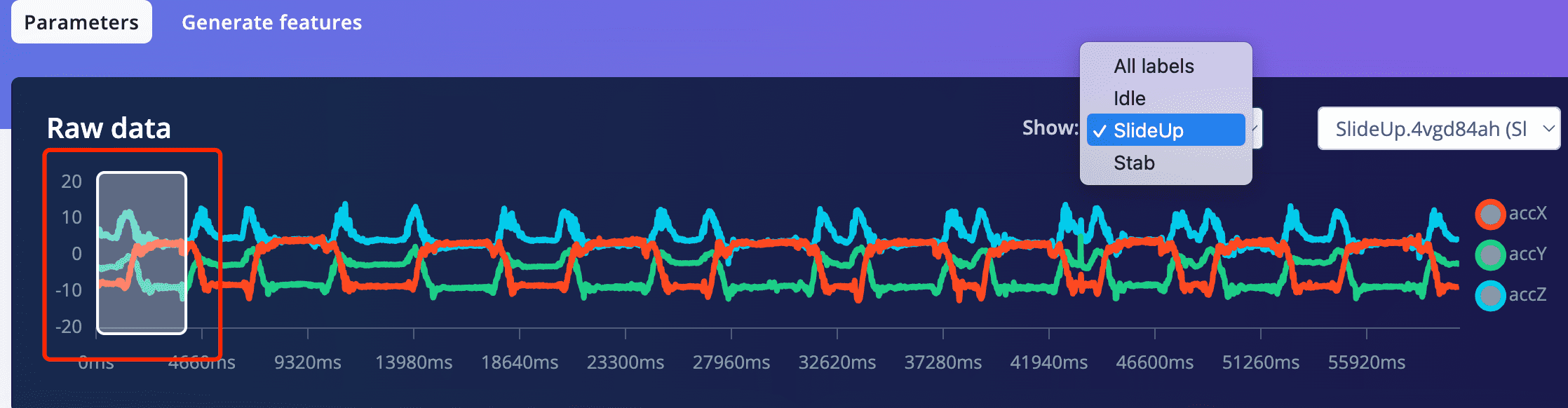
4.4 SlideUp gestures for the new sword
5: Analyze the data sampled
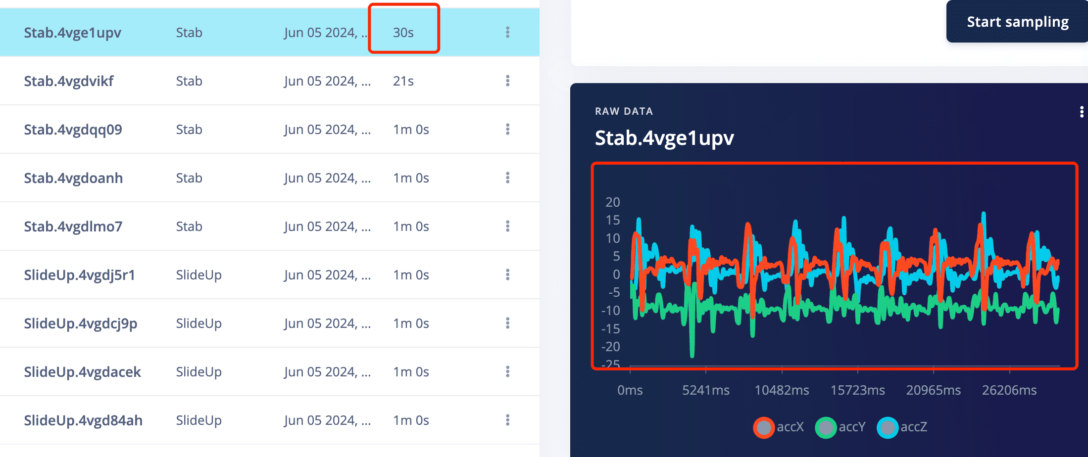
5.1 Click on one recode of data, then you can see the three waves of the three accelerometer data
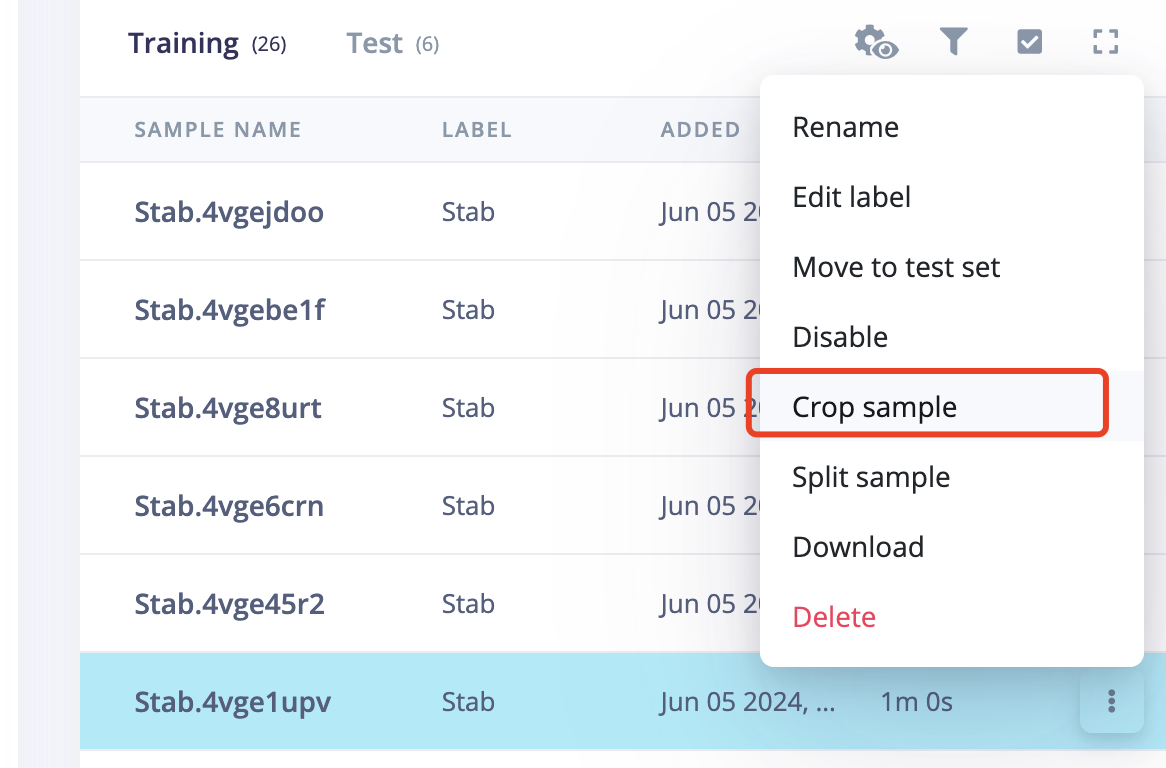
5.2 Operate on the raw data, crop abnormal data
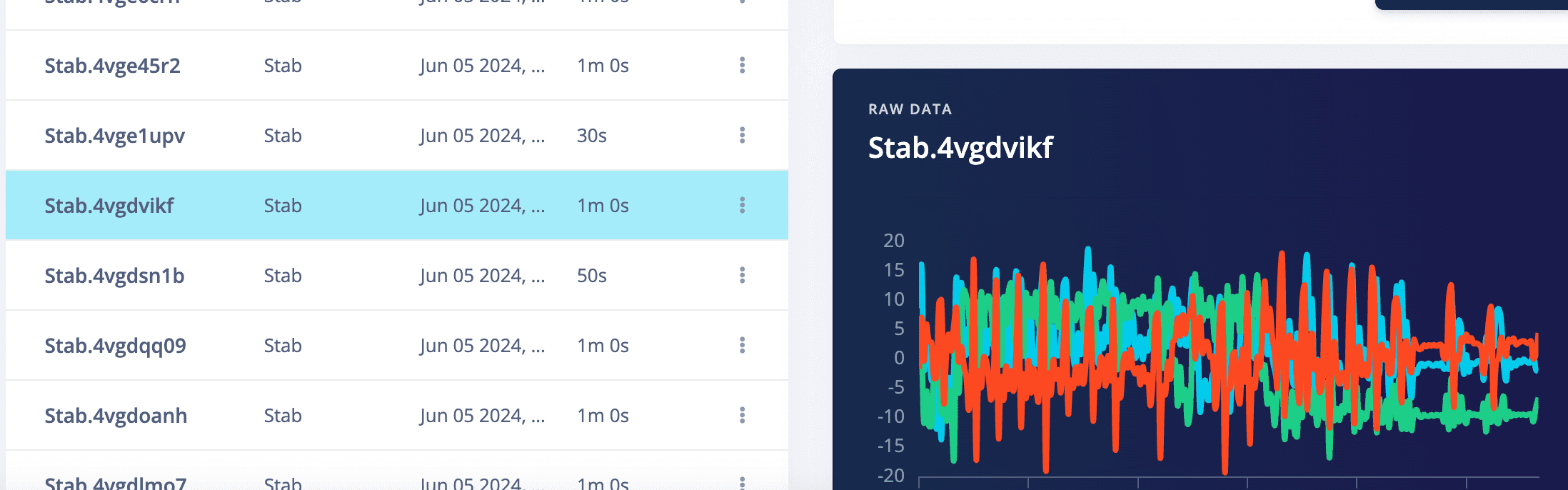
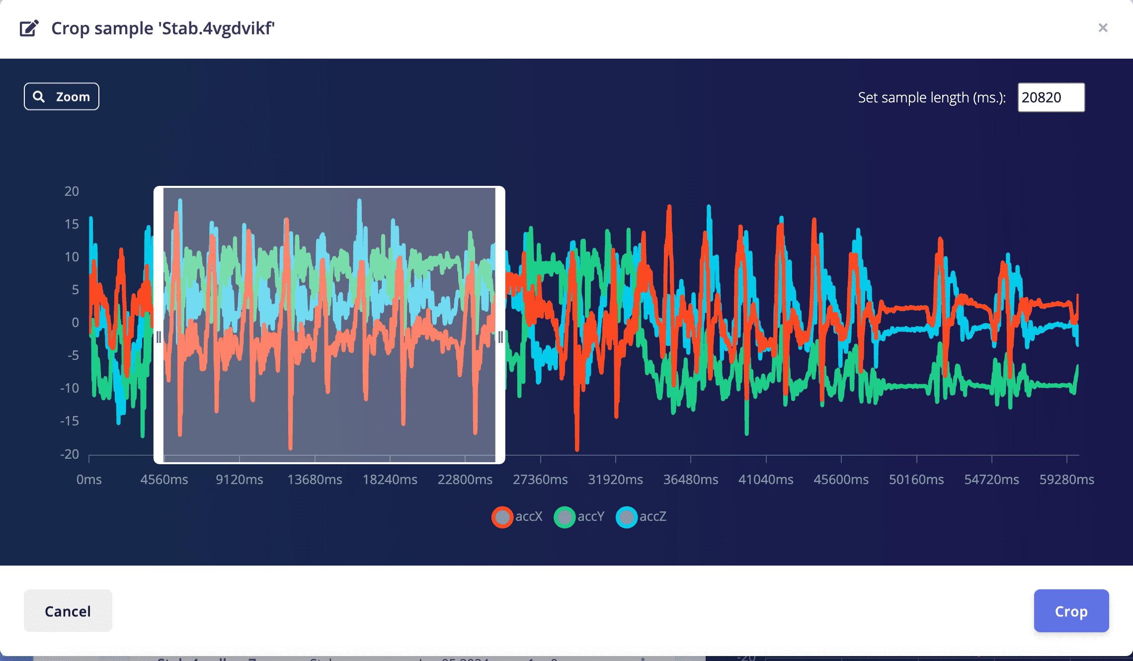
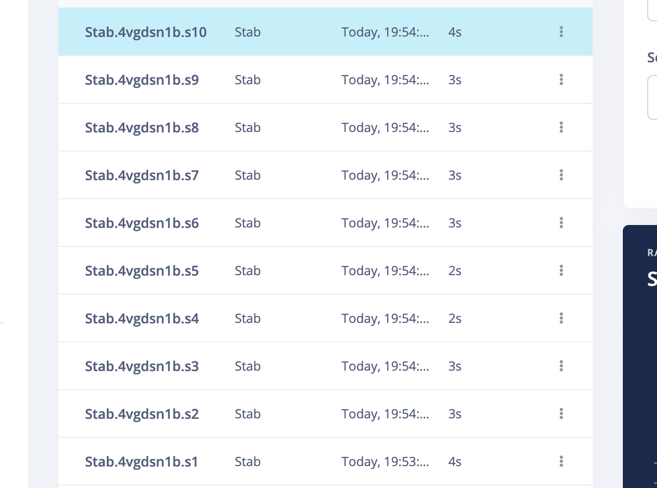
After crop, pnly the selected data was kept
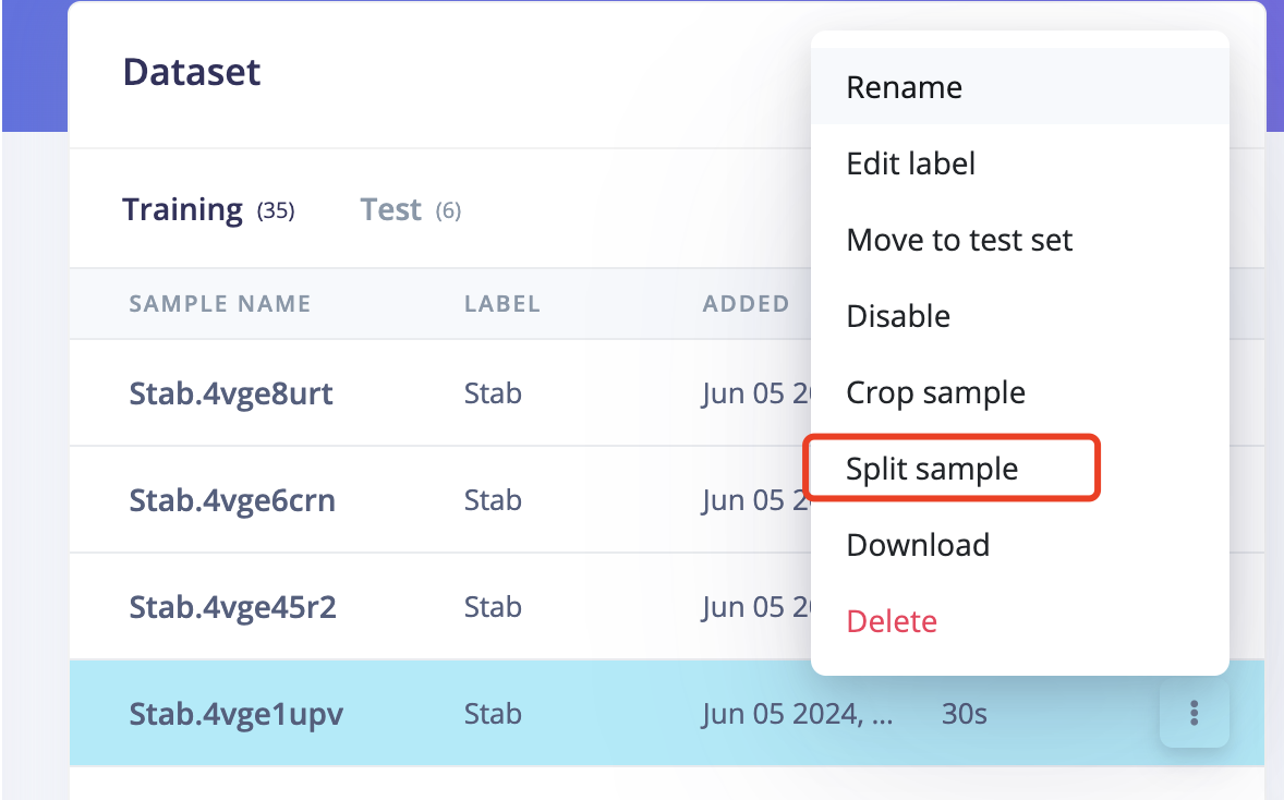
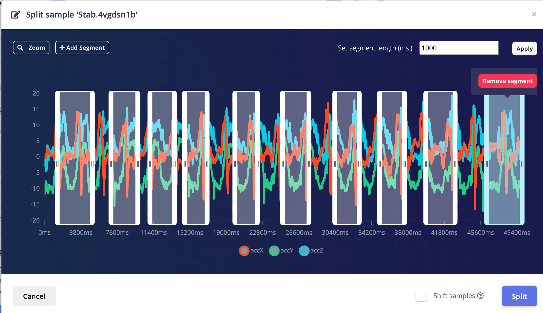
5.3 Operate on the raw data, split the data. I used to think that my slide up should only contain the slide from down to up part, and should not contain the up to down part.So I tried the slide up to split the data to only include the down to up part.
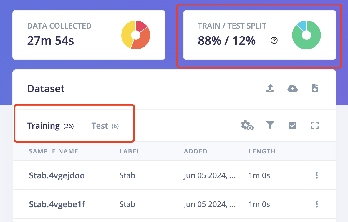
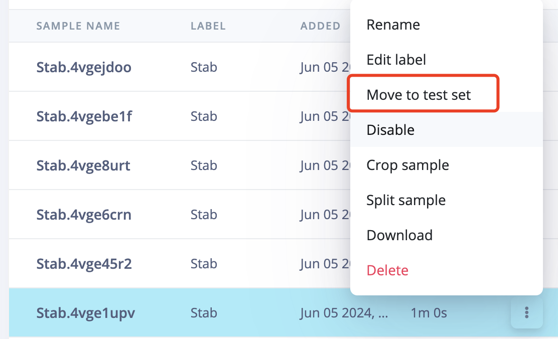
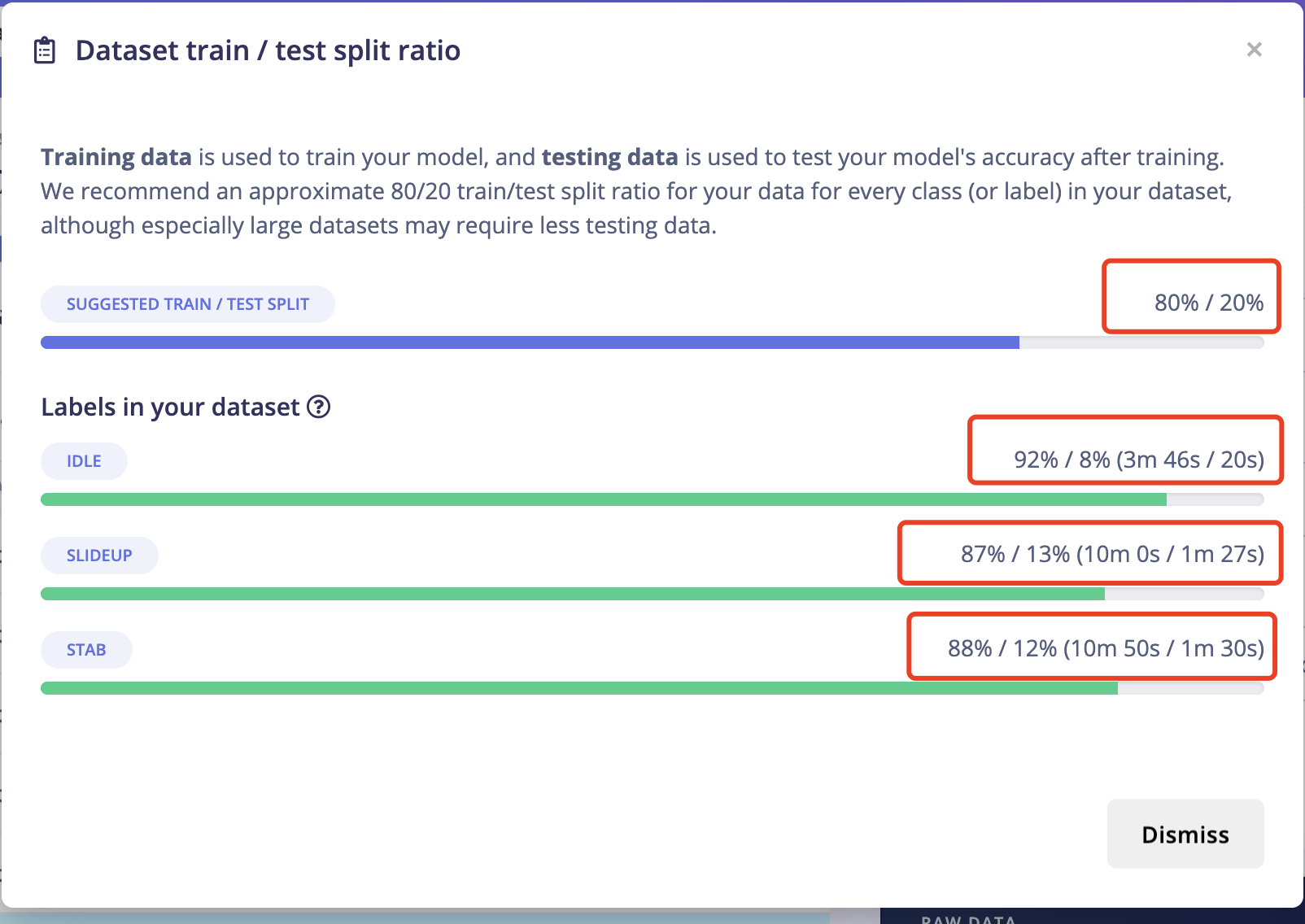
5.4 IMPORTANT!Another very important thing is to ensure that the percentage of training data and test data is 80% to 20%. Because you still need some data to test the recognition accuracy rate of the generated model. Click on "Train&Test" above, and you can see the ratio of training data and test data for each different label. Move the existing data to the test data or sample more data for testing.
6: Impulse Design
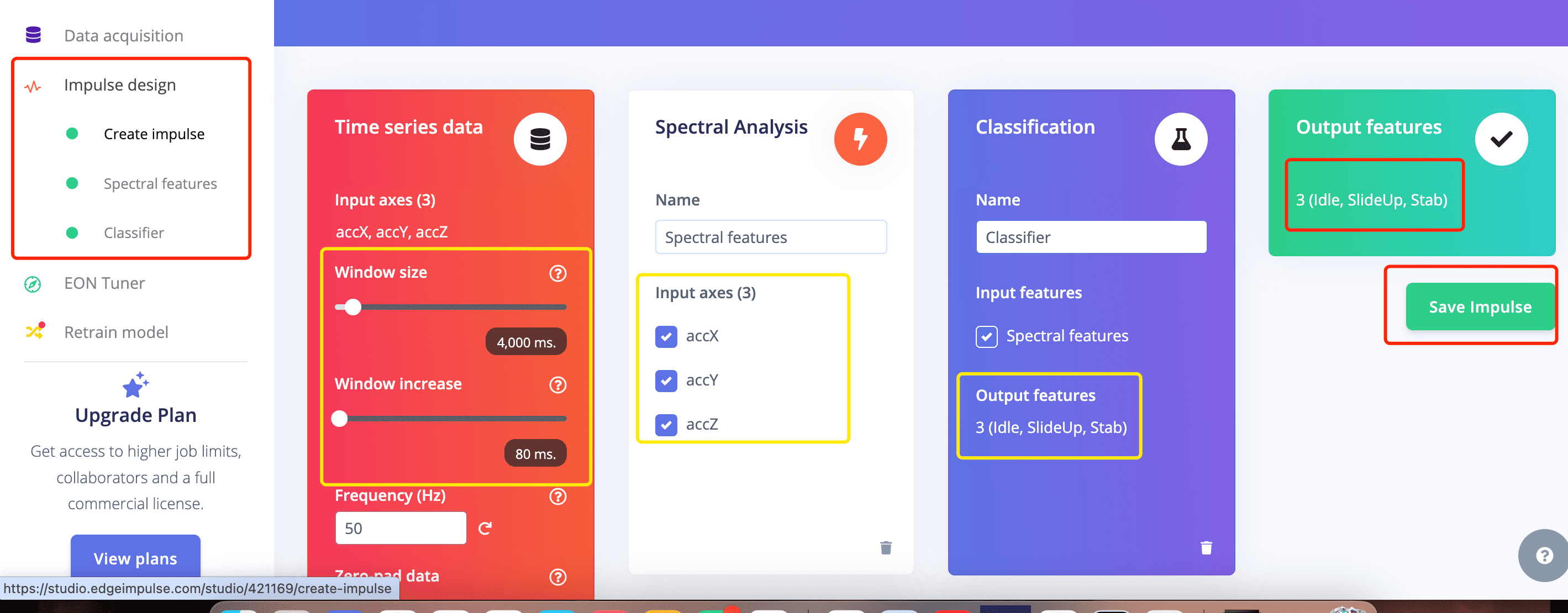
6.1 Create Impulse:
Now we can finally forward all the data to impulse to train the data and generate features
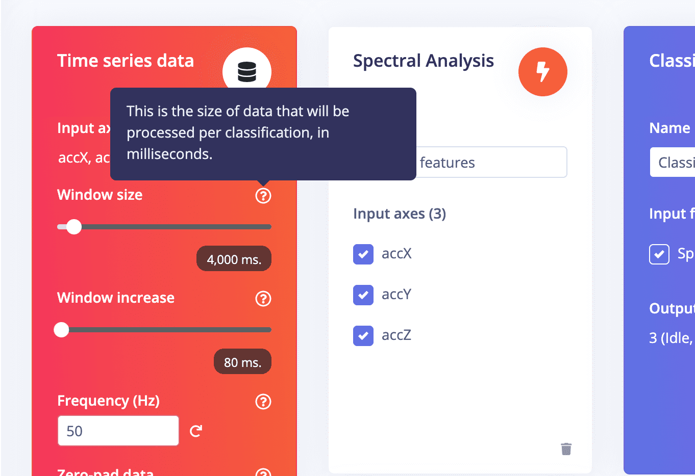
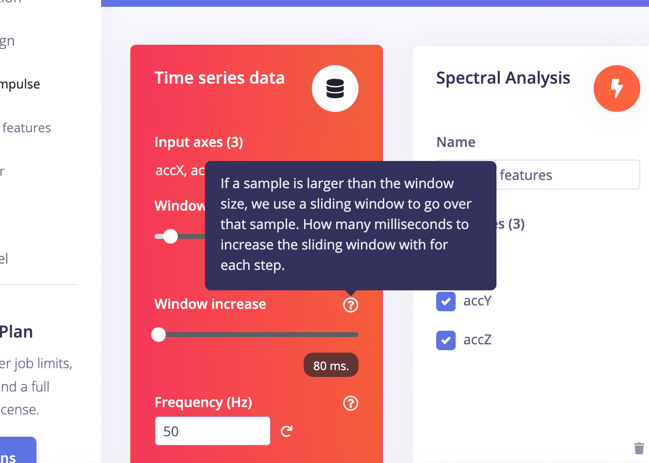
When move to impulse, it is needed to set the window size and window increase based on your data cycle
You can go to next page to check if the window size is set properly, if not, you can go back here to change
6.2 Spectral Features:
- First,you can check each record of the data of each lable to decide if your window size is set proper or now.
For me the window size has properly included a full cycle of a slideup and one or more cycle of a stab. so it is fine.
But if your window size is too small, it won't include all the features of one gesture cycle.

- IMPORTANT!The parameter setting are very important actually.
You should try diffrent parameters and observe the result on the right side to choose the proper one if you don't want to go too deep.
- IMPORTANT!The parameter setting are very important actually.
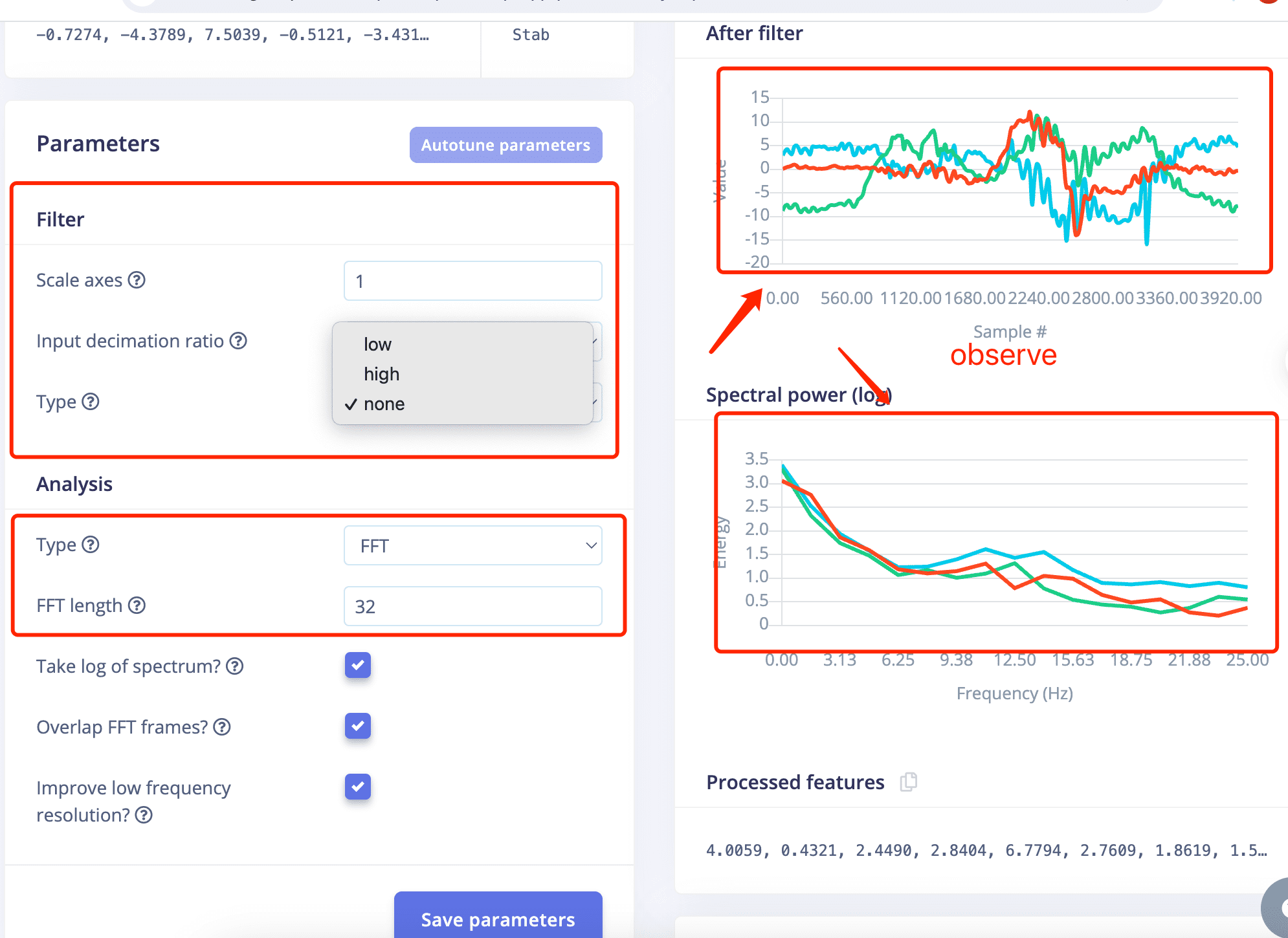
- IMPORTANT!Choose different lable to observe first!
- Lable Stab, Low ,FFT 16 VS Lable SlideUp,Low, FFT 16
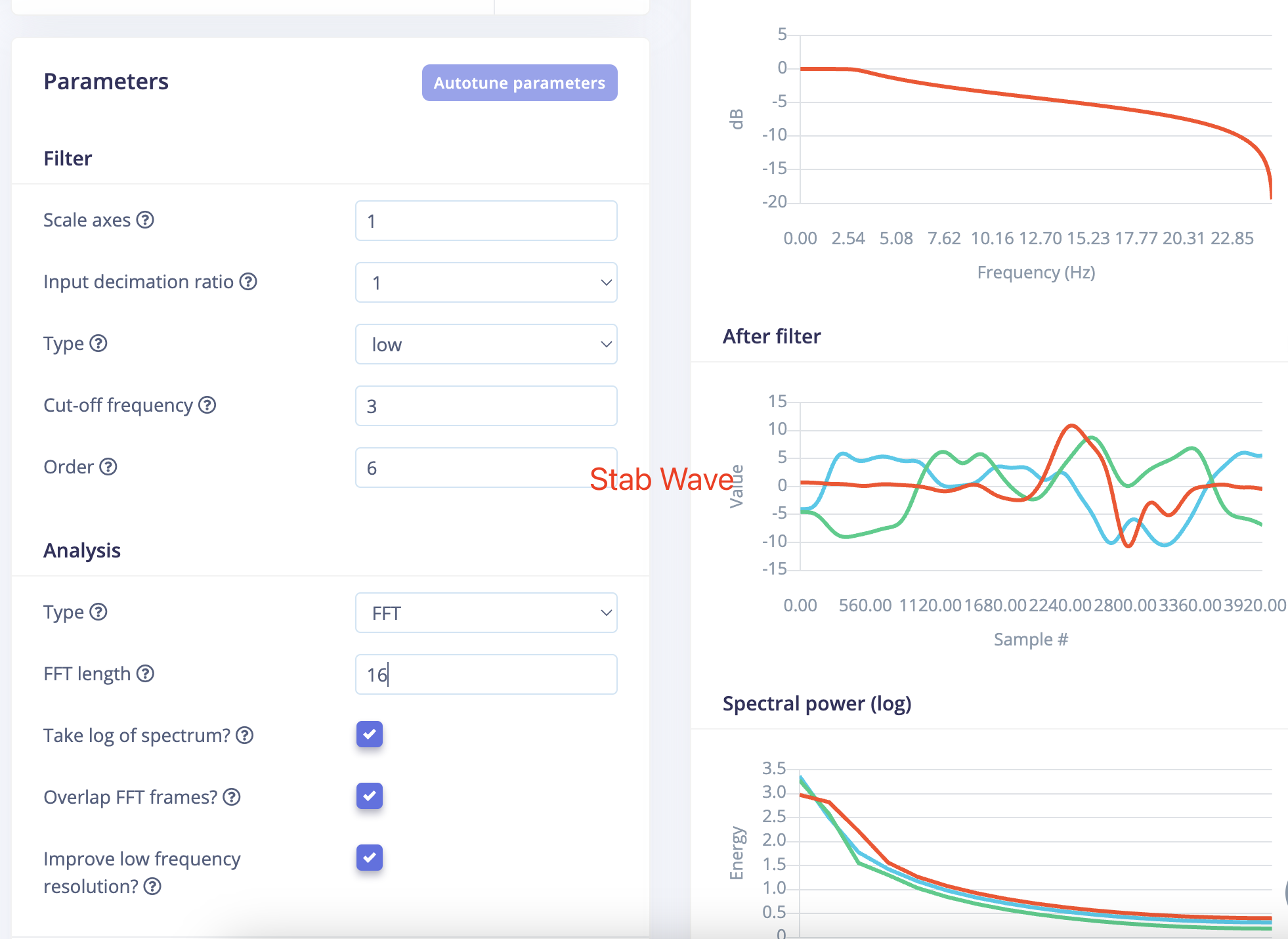
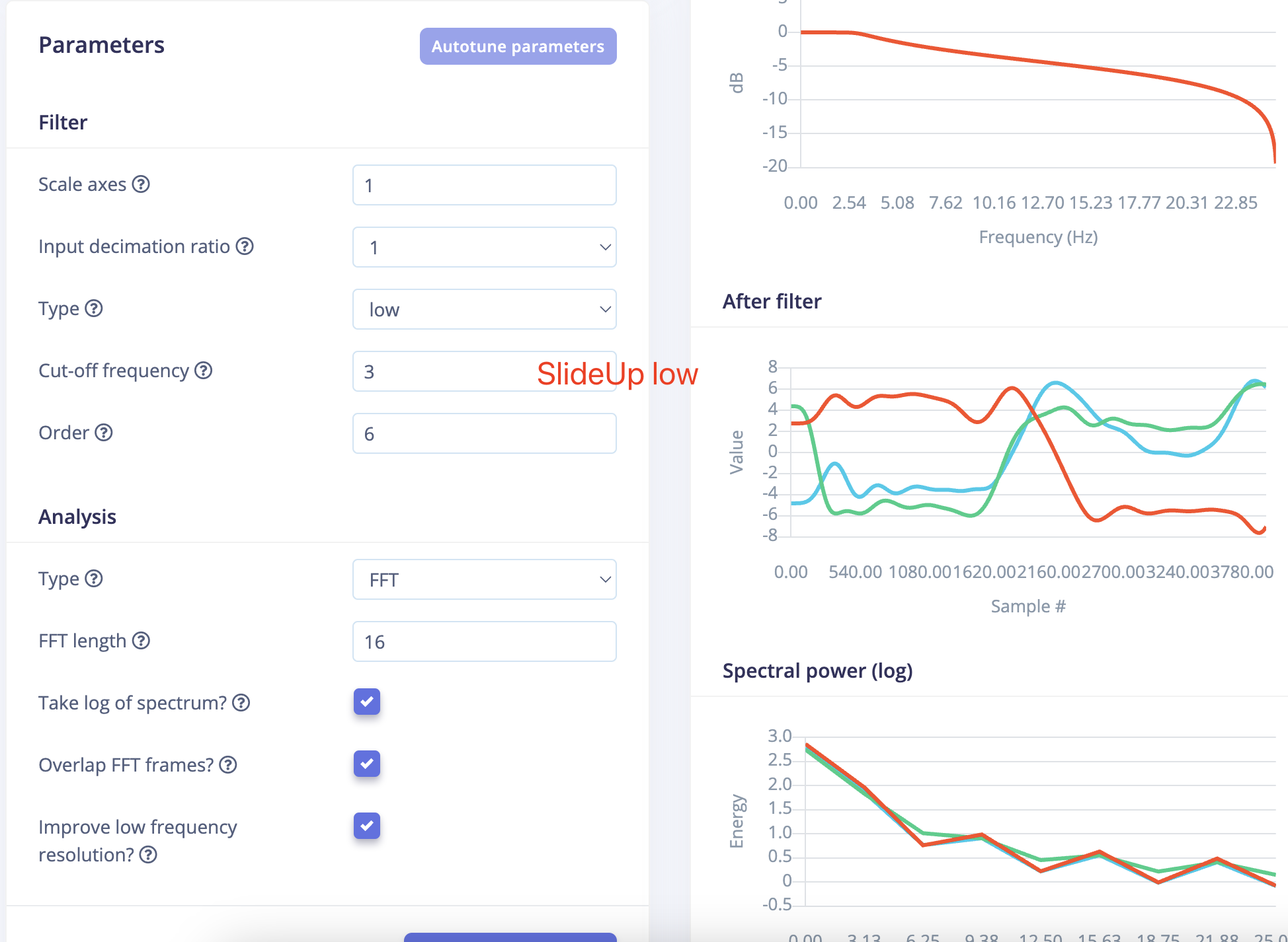
- The waveforms after filtering turned out to be so similar that it actually surprised me.
Becuase the two gestures are very much not alike.
- And let's go with this setting and see what happens next.
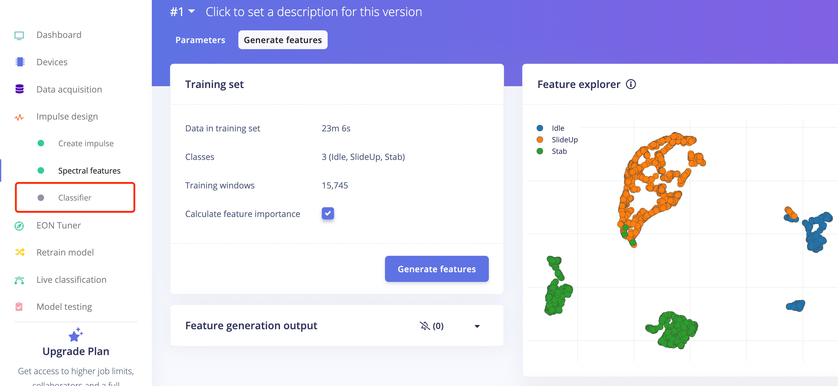
- Proceed to feature generation, and it will take a while to generate features.
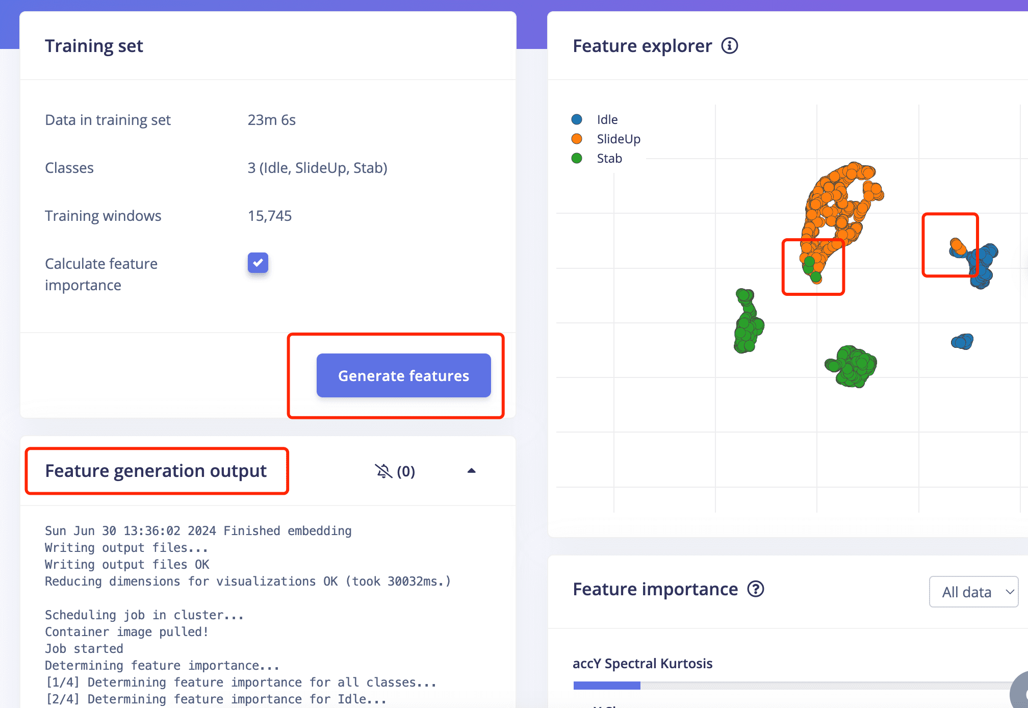
- The result doesn't look very well since there are some overlapping parts of the feature of SlideUo and Stab,
also overlapping parts of the feature of SlideUp and Idle .
- Then you can move on to Classifier on the left side of pannel to proceed.
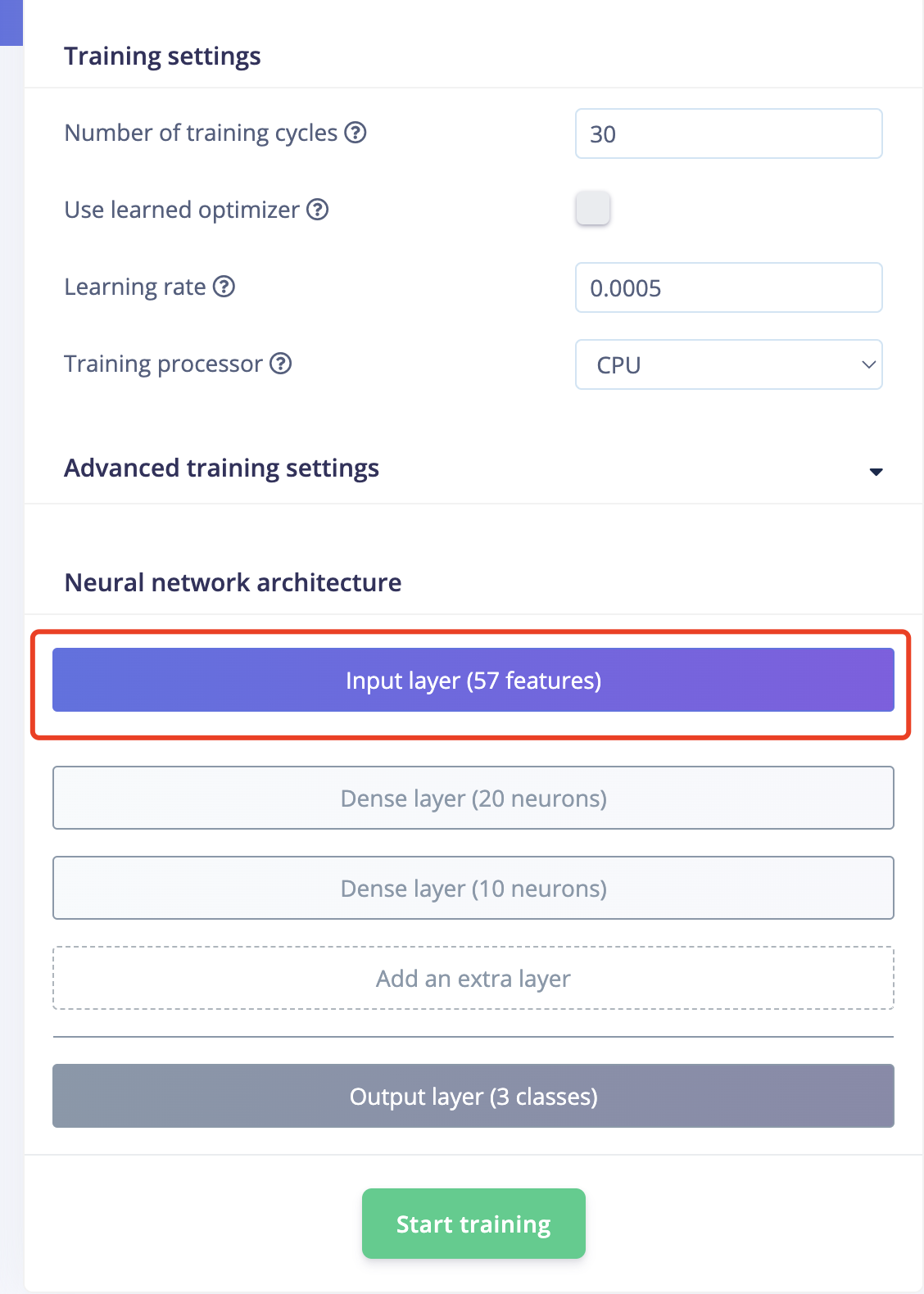
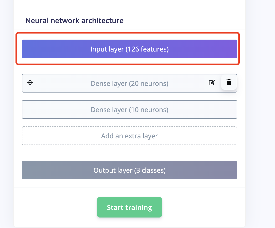
- It doesn't look well because only 57 features are generated. Obviously, the more features, the better.

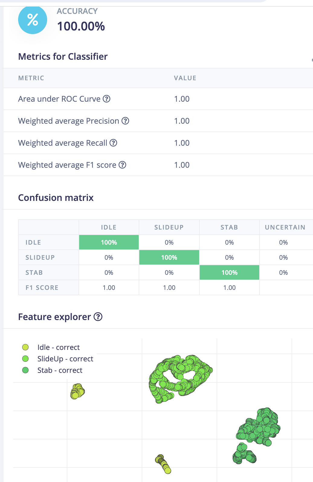
- The training result looks good with 100% accuracy,but it is also very important to test it.
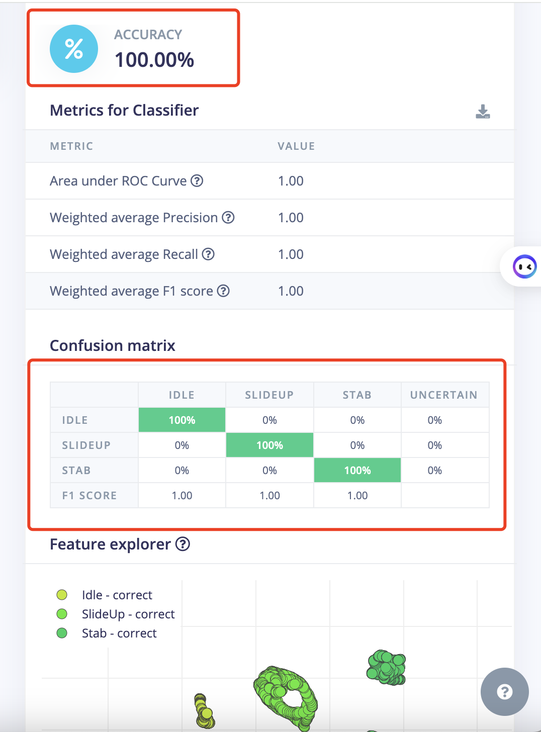
- Go to Module Test and see the result.
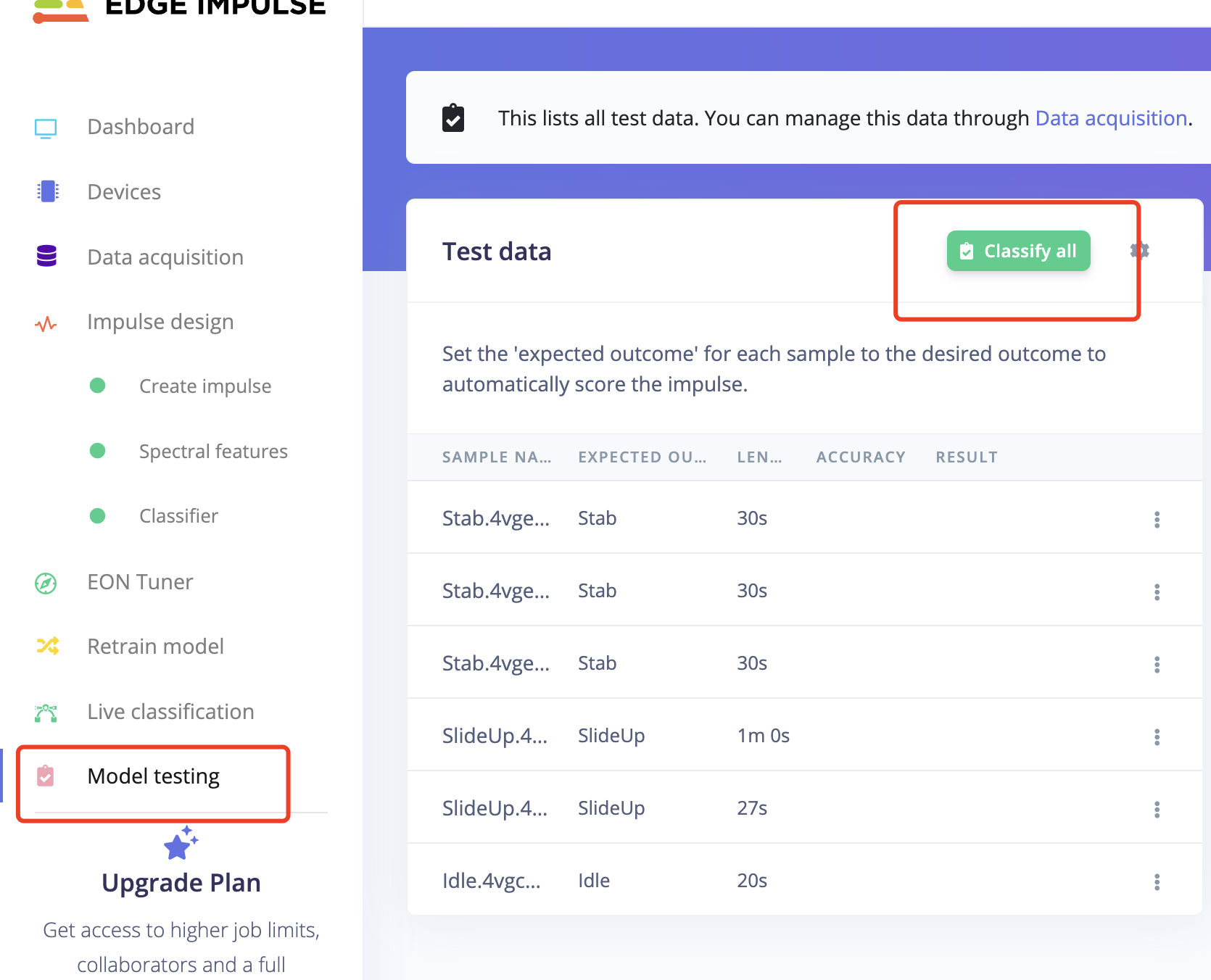
- It turns out Good!.
- But Let's go back to change the parameter and test more!.
- If I change the parameter to be none, FFT 32 for each laber. The wave after filter will be more different.
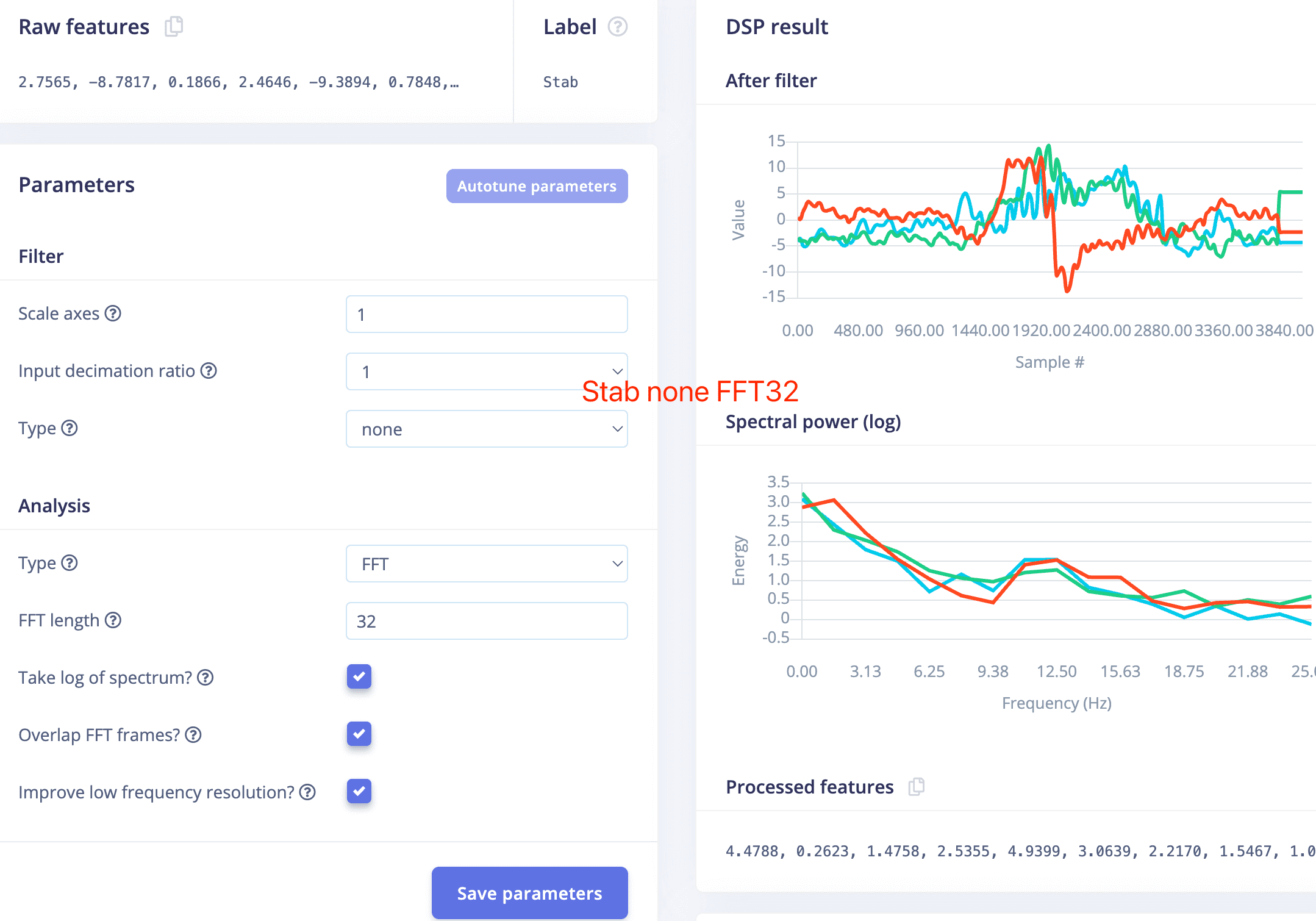
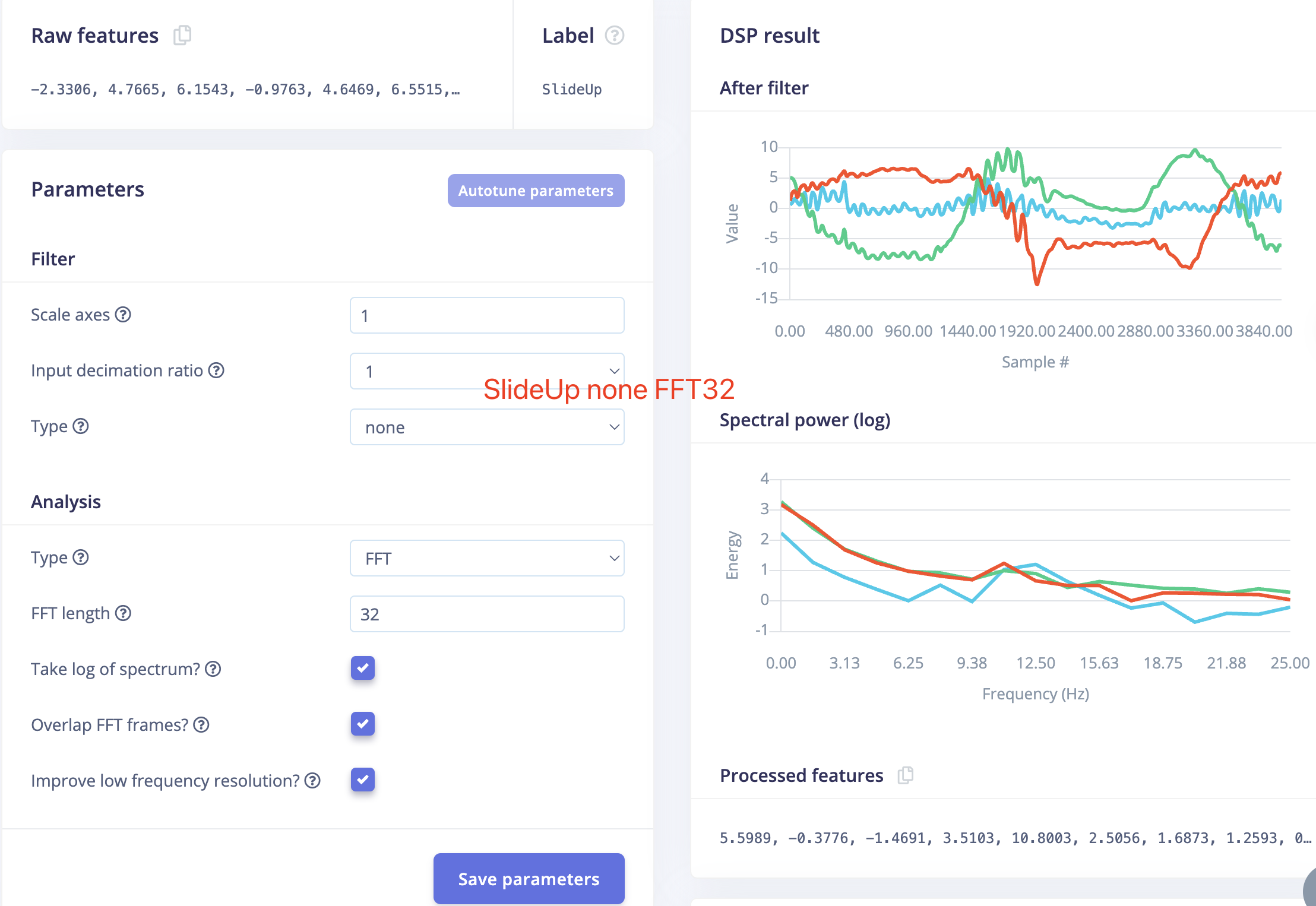
- Feature result looks better, but still have some overlapping part.
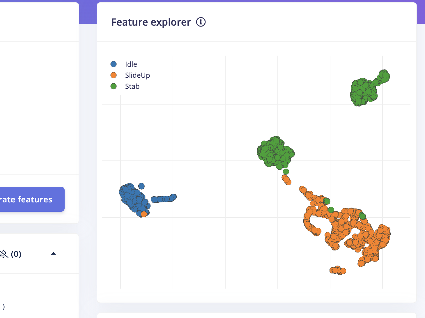
- More features are generated.
- Accuracy is also 100%.
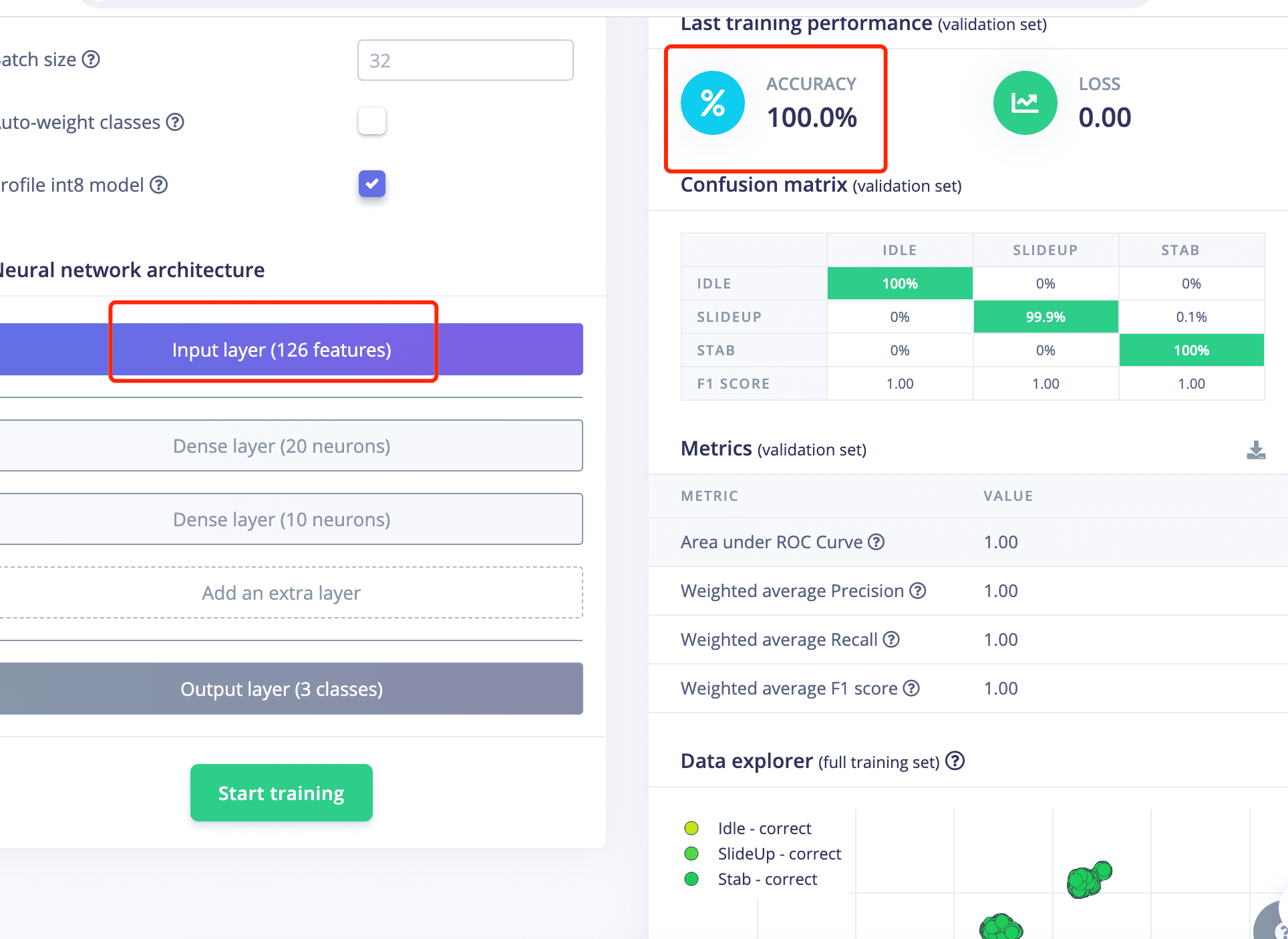
- The module test result is also good.
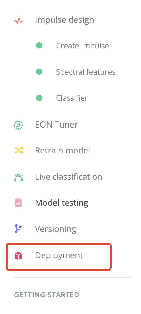
7: Generate Arduino Libary
7.1 Go to "Deployment"
7.2 Serach for "Arduino Library"
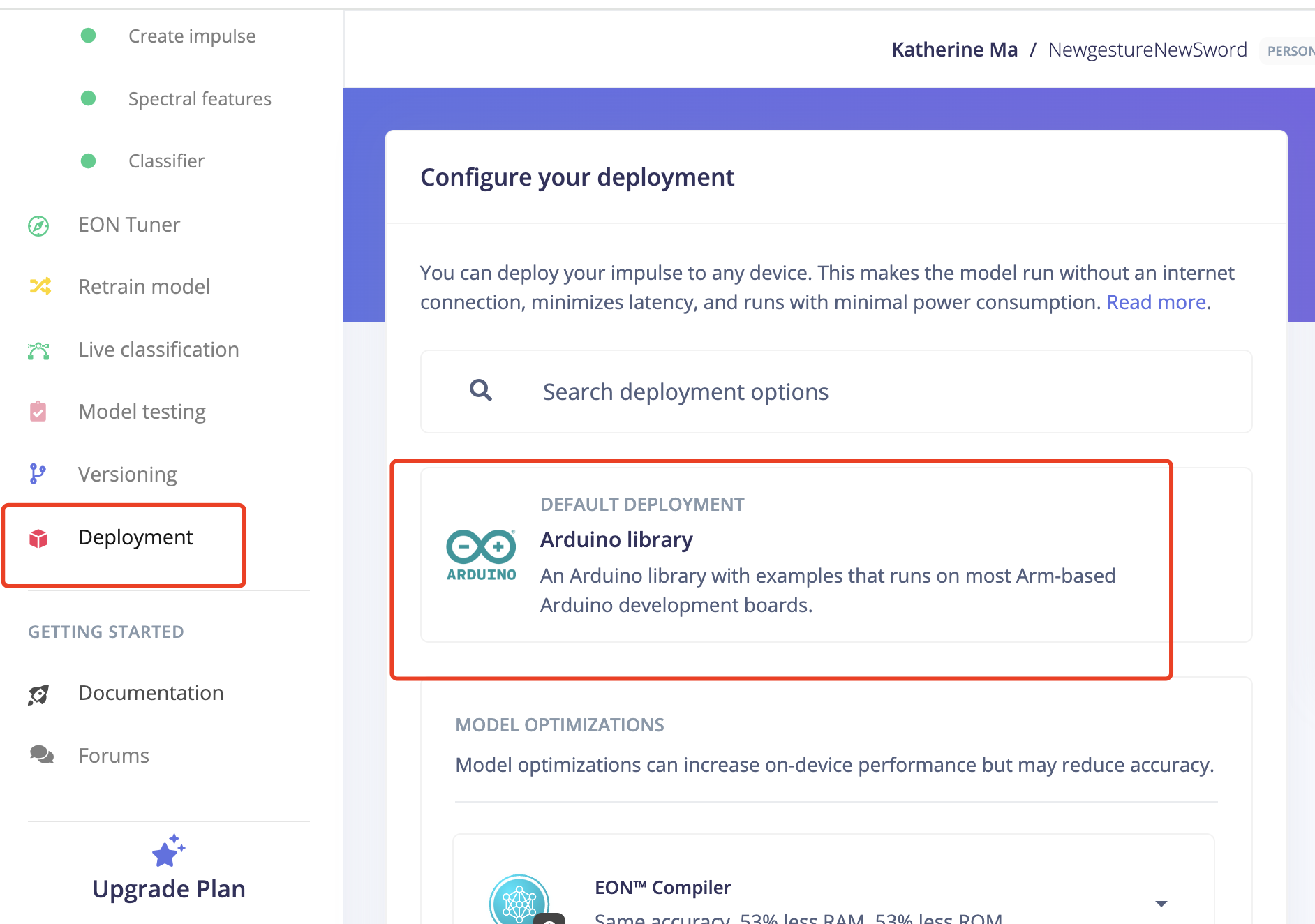
7.3 Click Build

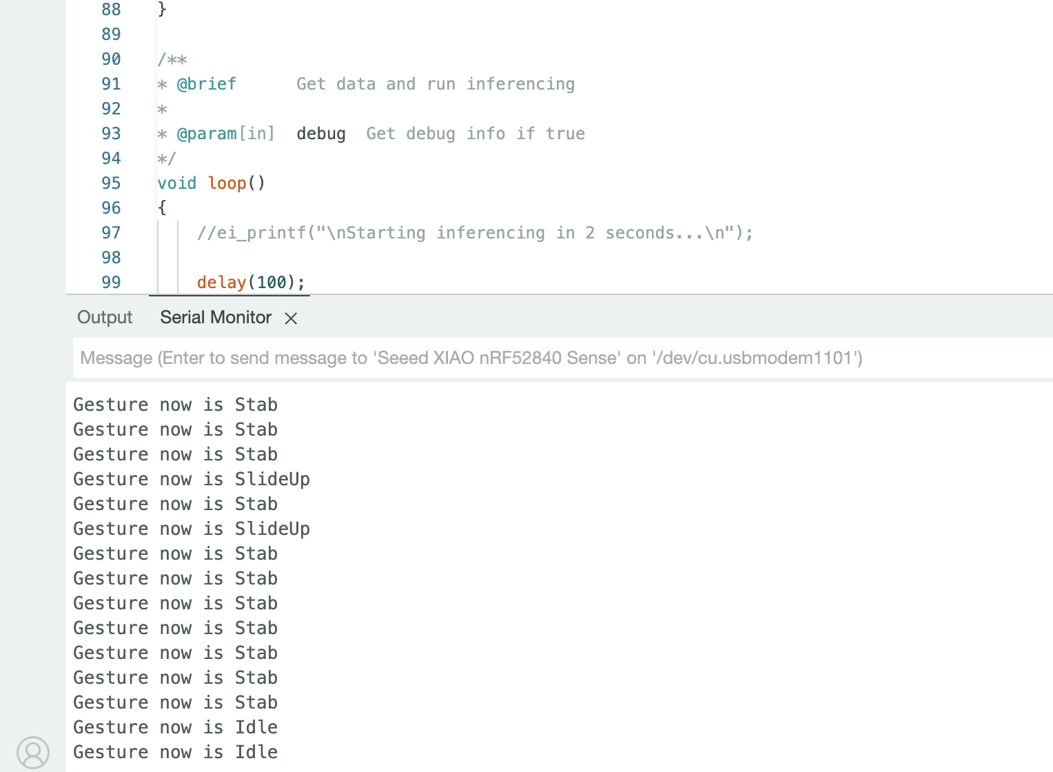
Step5. Arduino Programming
Deploy the arduino libary onto the XIAO nRF52850 Sense
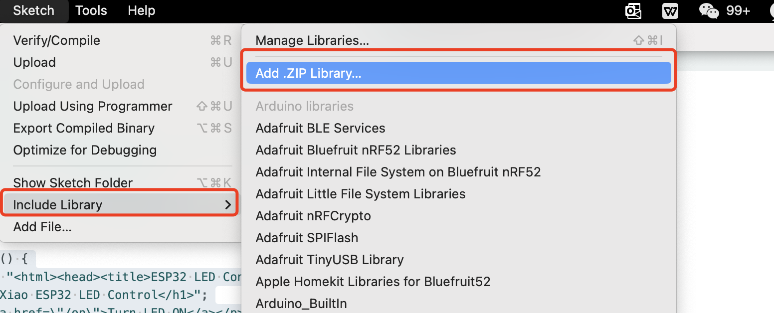
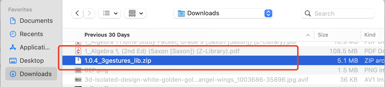
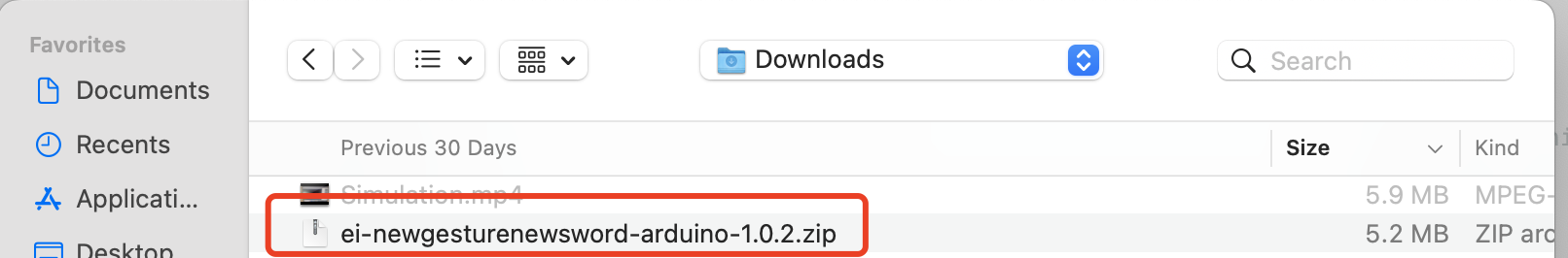
Once the library generated, we need to add it on the arduino as new library for that, choose Add .ZIP Library from the Include Library option from Sketch.
The Arduino Code to recognize the gestures
    /* Includes ---------------------------------------------------------------- */
    // Include the necessary libraries for activity monitoring and IMU functionality
    #include <ActivityMonitor_Xiao_Sense_inferencing.h>  //replace the library name with yours
    #include "LSM6DS3.h"

    /* Constant defines -------------------------------------------------------- */
    // Conversion factor from acceleration in g to m/s²
    #define CONVERT_G_TO_MS2    9.80665f
    // Maximum accepted acceleration range
    #define MAX_ACCEPTED_RANGE  2.0f        // starting 03/2022, models are generated setting range to +-2, but this example use Arudino library which set range to +-4g. If you are using an older model, ignore this value and use 4.0f instead
    // Interval calculation based on the specified frequency
    #define INTERVAL_MS (1000 / (FREQUENCY_HZ + 1))
    // Variable to store the last interval timestamp
    static unsigned long last_interval_ms = 0;

    // Initialize the LSM6DS3 IMU with I2C mode and device address 0x6A
    LSM6DS3 myIMU(I2C_MODE, 0x6A);

    // Flag for enabling debug mode for neural network
    static bool debug_nn = false; // Set this to true to see e.g. features generated from the raw signal

    /**
    * @brief      Arduino setup function
    */
    void setup()
    {
        // put your setup code here, to run once:
        // Initialize serial communication at 115200 baud rate
        Serial.begin(115200);
        // Wait for serial connection (needed for some cases)
        // comment out the below line to cancel the wait for USB connection (needed for native USB)
        while (!Serial);
        Serial.println("Edge Impulse Inferencing Demo");

        // Initialize the IMU
        if (!myIMU.begin()) {
            ei_printf("Failed to initialize IMU!\r\n");
        }
        else {
            ei_printf("IMU initialized\r\n");
        }

        // Check if the number of raw samples per frame matches the expected value
        if (EI_CLASSIFIER_RAW_SAMPLES_PER_FRAME!= 3) {
            ei_printf("ERR: EI_CLASSIFIER_RAW_SAMPLES_PER_FRAME should be equal to 3 (the 3 sensor axes)\n");
            return;
        }
    }

    /**
     * @brief Return the sign of the number
     *
     * @param number
     * @return int 1 if positive (or 0) -1 if negative
     */
    float ei_get_sign(float number) {
        // Function to determine the sign of a number
        return (number >= 0.0)? 1.0 : -1.0;
    }

    /**
    * @brief      Get data and run inferencing
    *
    * @param[in]  debug  Get debug info if true
    */
    void loop()
    {
        //ei_printf("\nStarting inferencing in 2 seconds...\n");

        // Delay for 2 seconds before starting inferencing
        delay(2000);

        //ei_printf("Sampling...\n");

        // Allocate a buffer for the IMU data
        float buffer[EI_CLASSIFIER_DSP_INPUT_FRAME_SIZE] = { 0 };

        // Read IMU data and perform range checks and conversions
        for (size_t ix = 0; ix < EI_CLASSIFIER_DSP_INPUT_FRAME_SIZE; ix += 3) {
            // Determine the next sampling time
            uint64_t next_tick = micros() + (EI_CLASSIFIER_INTERVAL_MS * 1000);

            // Read acceleration data from the IMU
            buffer[ix+0] = myIMU.readFloatAccelX();
            buffer[ix+1] = myIMU.readFloatAccelY();
            buffer[ix+2] = myIMU.readFloatAccelZ();

            // Clip the data if it exceeds the maximum accepted range
            for (int i = 0; i < 3; i++) {
                if (fabs(buffer[ix + i]) > MAX_ACCEPTED_RANGE) {
                    buffer[ix + i] = ei_get_sign(buffer[ix + i]) * MAX_ACCEPTED_RANGE;
                }
            }

            // Convert acceleration from g to m/s²
            buffer[ix + 0] *= CONVERT_G_TO_MS2;
            buffer[ix + 1] *= CONVERT_G_TO_MS2;
            buffer[ix + 2] *= CONVERT_G_TO_MS2;

            // Delay to match the sampling interval
            delayMicroseconds(next_tick - micros());
        }

        // Prepare the data for classification
        signal_t signal;
        int err = numpy::signal_from_buffer(buffer, EI_CLASSIFIER_DSP_INPUT_FRAME_SIZE, &signal);
        if (err!= 0) {
            ei_printf("Failed to create signal from buffer (%d)\n", err);
            return;
        }

        // Run the classifier
        ei_impulse_result_t result = { 0 };

        err = run_classifier(&signal, &result, debug_nn);
        if (err!= EI_IMPULSE_OK) {
            ei_printf("ERR: Failed to run classifier (%d)\n", err);
            return;
        }

        // Print the classification results
        //ei_printf("Predictions ");
        //ei_printf("(DSP: %d ms., Classification: %d ms., Anomaly: %d ms.)",
        // result.timing.dsp, result.timing.classification, result.timing.anomaly);
        //ei_printf("\n");
        for (size_t ix = 0; ix < EI_CLASSIFIER_LABEL_COUNT; ix++) {
        //ei_printf("    %s: %.5f\n", result.classification[ix].label, result.classification[ix].value);
            if (result.classification[ix].value >.5) {
                ei_printf("%s \n", result.classification[ix]);
            }
        }

        //  if (result.classification[ix].value >.5) {
        //     ei_printf("    %s: %.5f\n", result.classification[ix].label, result.classification[ix].value);
        // }
        // }


#if EI_CLASSIFIER_HAS_ANOMALY == 1
        ei_printf("anomaly score: %.3f\n", result.anomaly);
#endif
    }

#if!defined(EI_CLASSIFIER_SENSOR) || EI_CLASSIFIER_SENSOR!= EI_CLASSIFIER_SENSOR_ACCELEROMETER
#error "Invalid model for current sensor"
#endif