Weekly assignments
- week 1. Project Management
- week 2. Computer Aided Design
- week 3. Computer Controlled Cutting
- week 4. Electronics Production
- week 5. 3D Scanning and Printing
- week 6. Embeded Programming
- week 7. Computer Controlled Machining
- week 8. Electronics Design
- week 9. Output Devices
- week 10. Mechanical design & Machine Design
- week 11. Break & Midterm Review
- week 12. Input devices
- week 13. Moulding and Casting
- week 14. Networking and communications
- week 15. Interface and application programming
- week 16. Wildcard week
- week 17. Applications And implications
- week 18. Project Development
- week 19. Invention, Intellectual Property and Income
2. Computer-Aided Design
This week I have started my new journey of learning 2D and 3D design, which is something new I have been eager to learn. And it did turn out to be a lot of fun
Research
The wonderful Fab Academy has provided a variety of choices of 2D and 3D design software for us to learn and choose from. I have tried two of the popular ones, and I really love the experience!
2D Design - GIMP
GIMP (GNU Image Manipulation Program) is a free and open-source 2D design software that offers a wide range of tools for tasks such as photo retouching, image composition, and image authoring. It provides features similar to those found in commercial software, including customizable brushes, layers, filters, and various selection tools. GIMP is widely used by graphic designers, illustrators, and photographers for creating and editing images.
3D Design - Fusion 360
Fusion 360 is a powerful 3D design software developed by Autodesk. It is widely used for computer-aided design (CAD), computer-aided engineering (CAE), and computer-aided manufacturing (CAM) tasks. Fusion 360 provides a comprehensive set of tools for creating 3D models, simulations, and renderings, making it suitable for various industries such as product design, engineering, and manufacturing. The software offers features for parametric modeling, sculpting, simulation, and collaboration, making it a versatile tool for designing and prototyping 3D models.
Useful links
Challenges
2D Design - GIMP
I think my biggest challenge is that I have zero experience on both 2D and 3D design.But after learning the tutoril and followed the steps one by one. I feel really happy to see my final output!
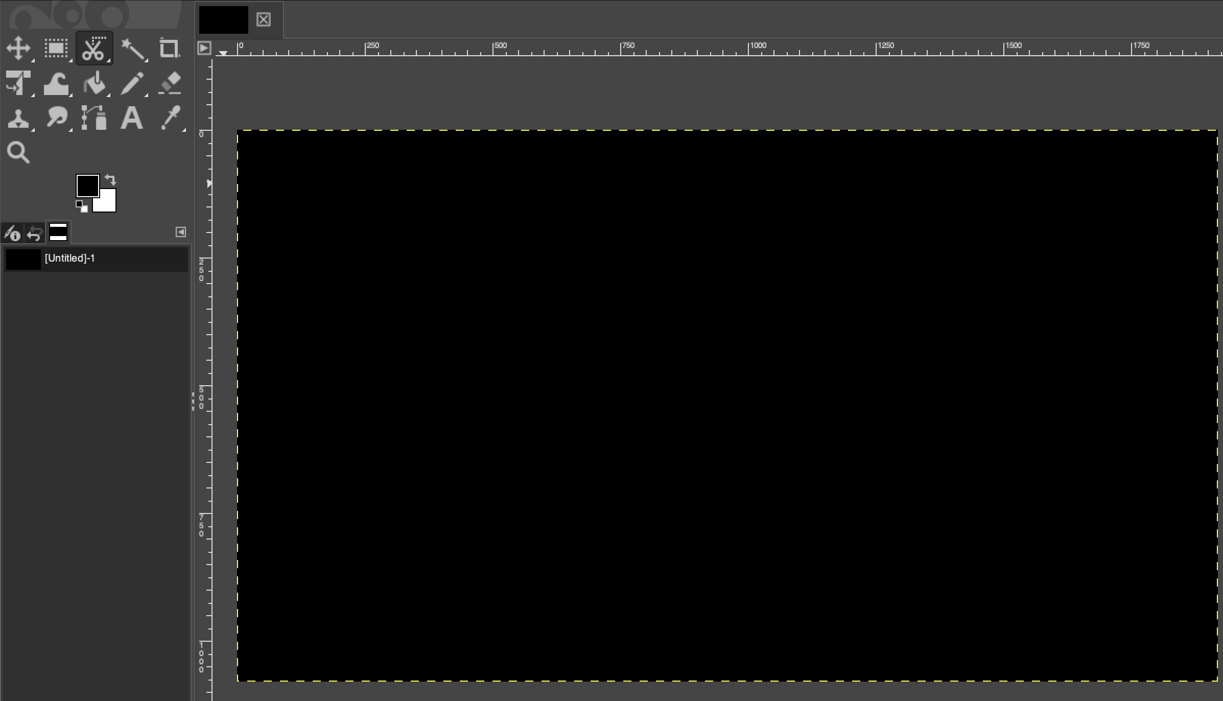
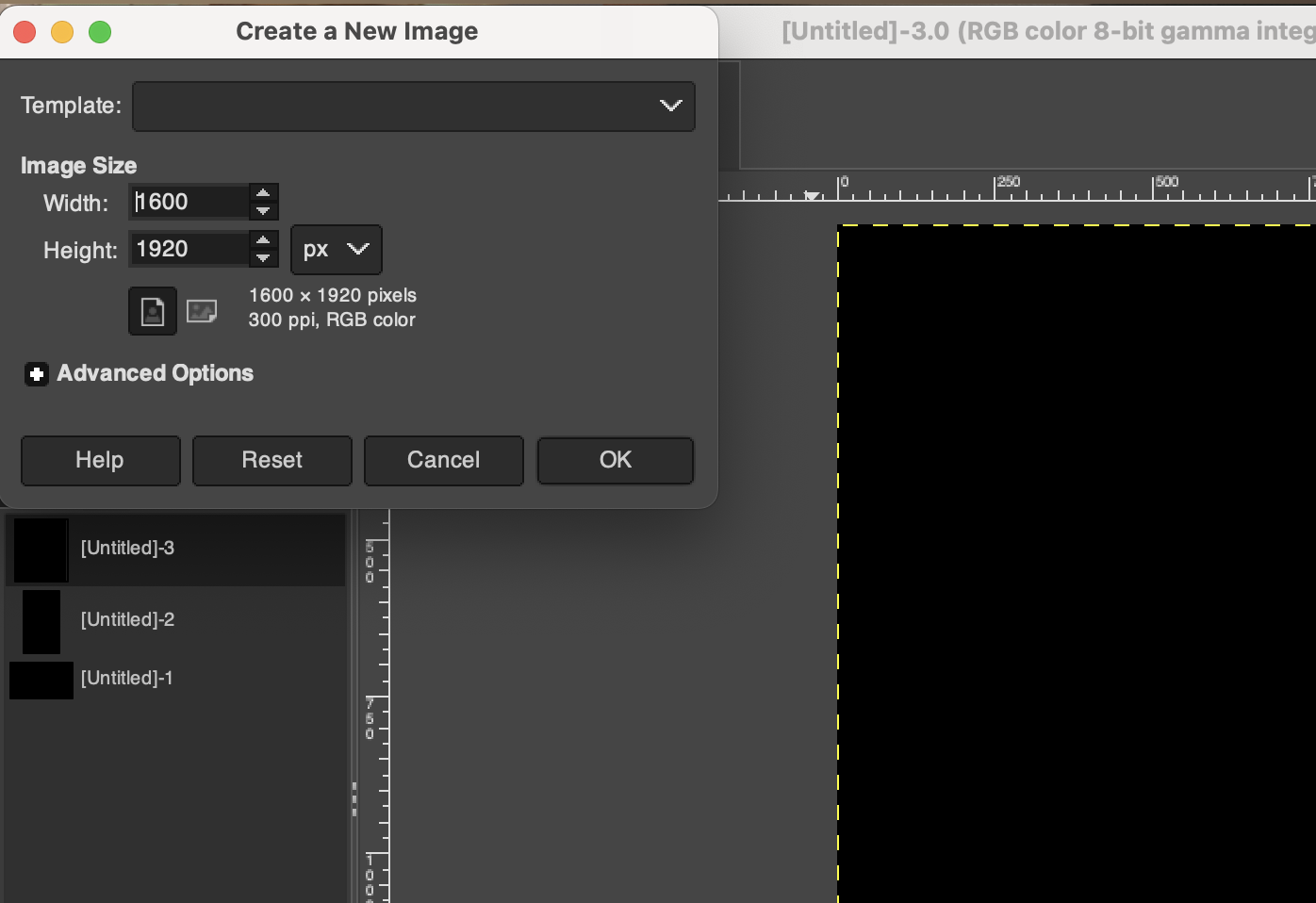
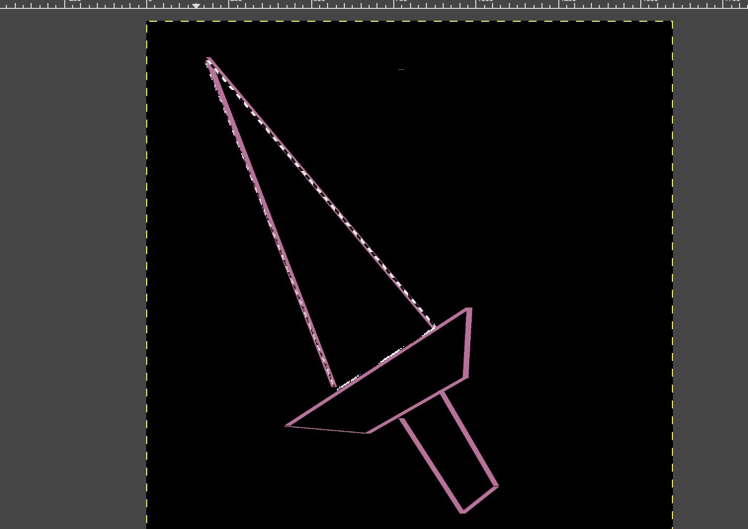
01 Create my first draft of gimp
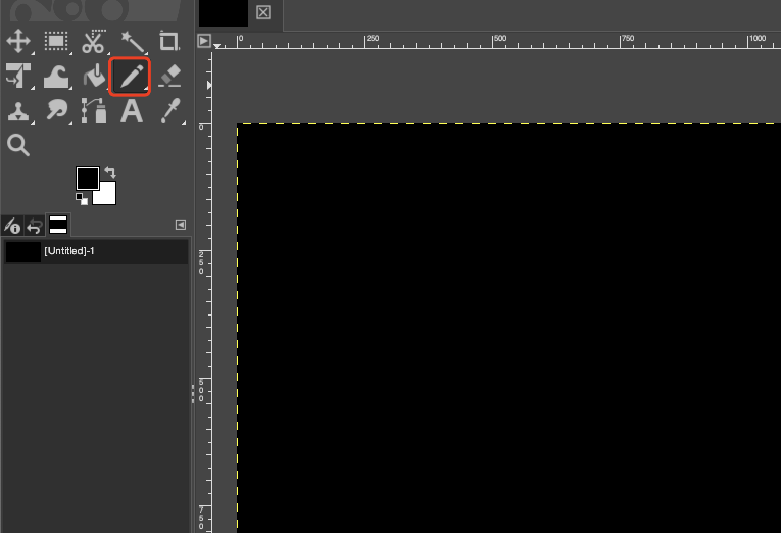
02 Choose pencil tool to draw lines and if you press shift then you can draw straight lines.
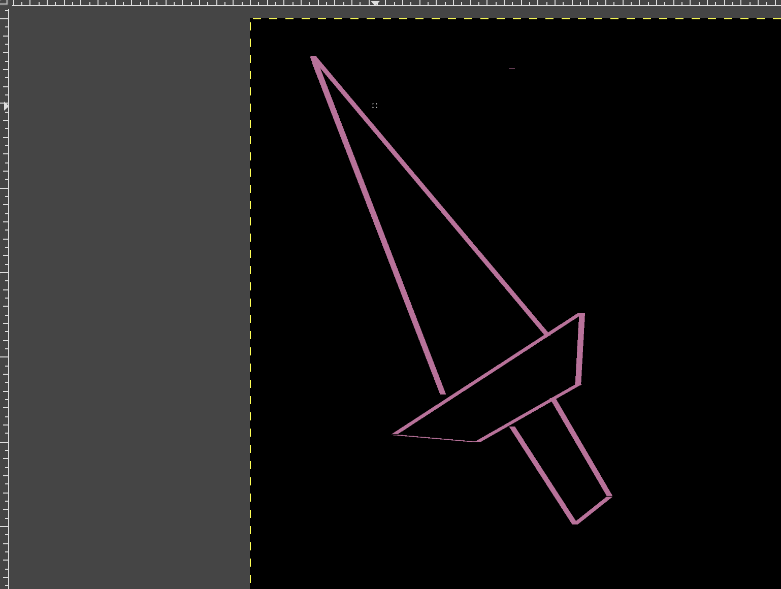
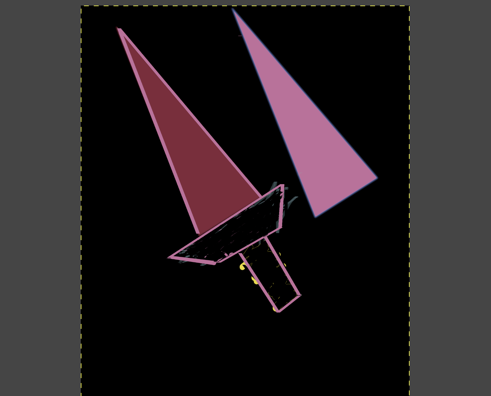
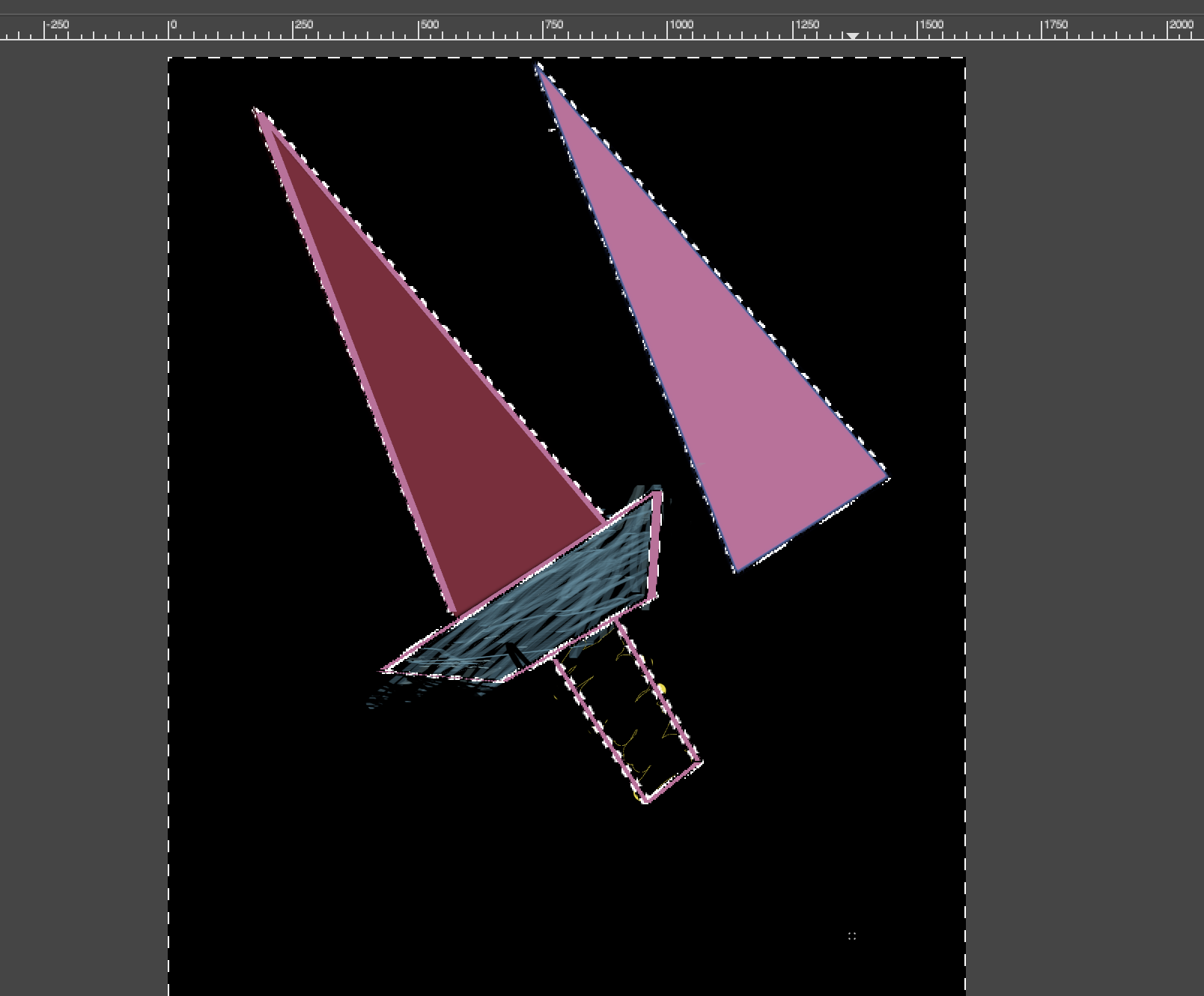
I used straight lines to draw a sword like below:
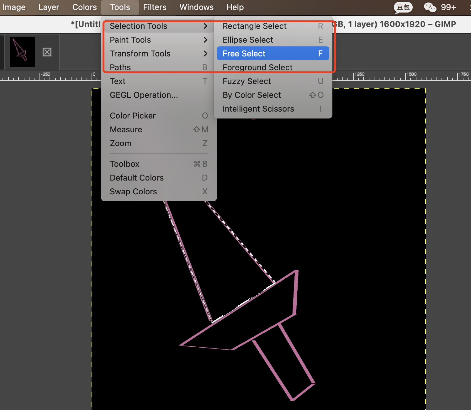
03 Use the selection Tool-> free select
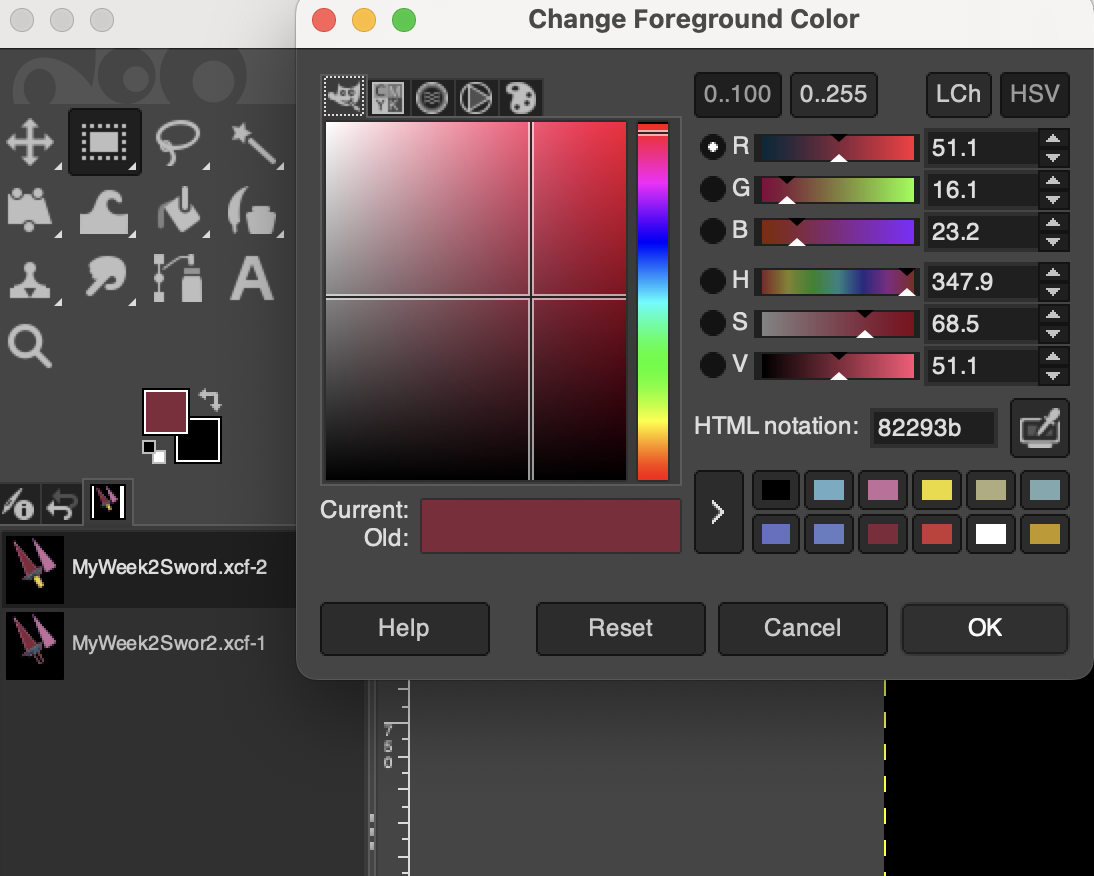
04 Fill color in selected part
05 Use the Tool-> Transform Tool->Move
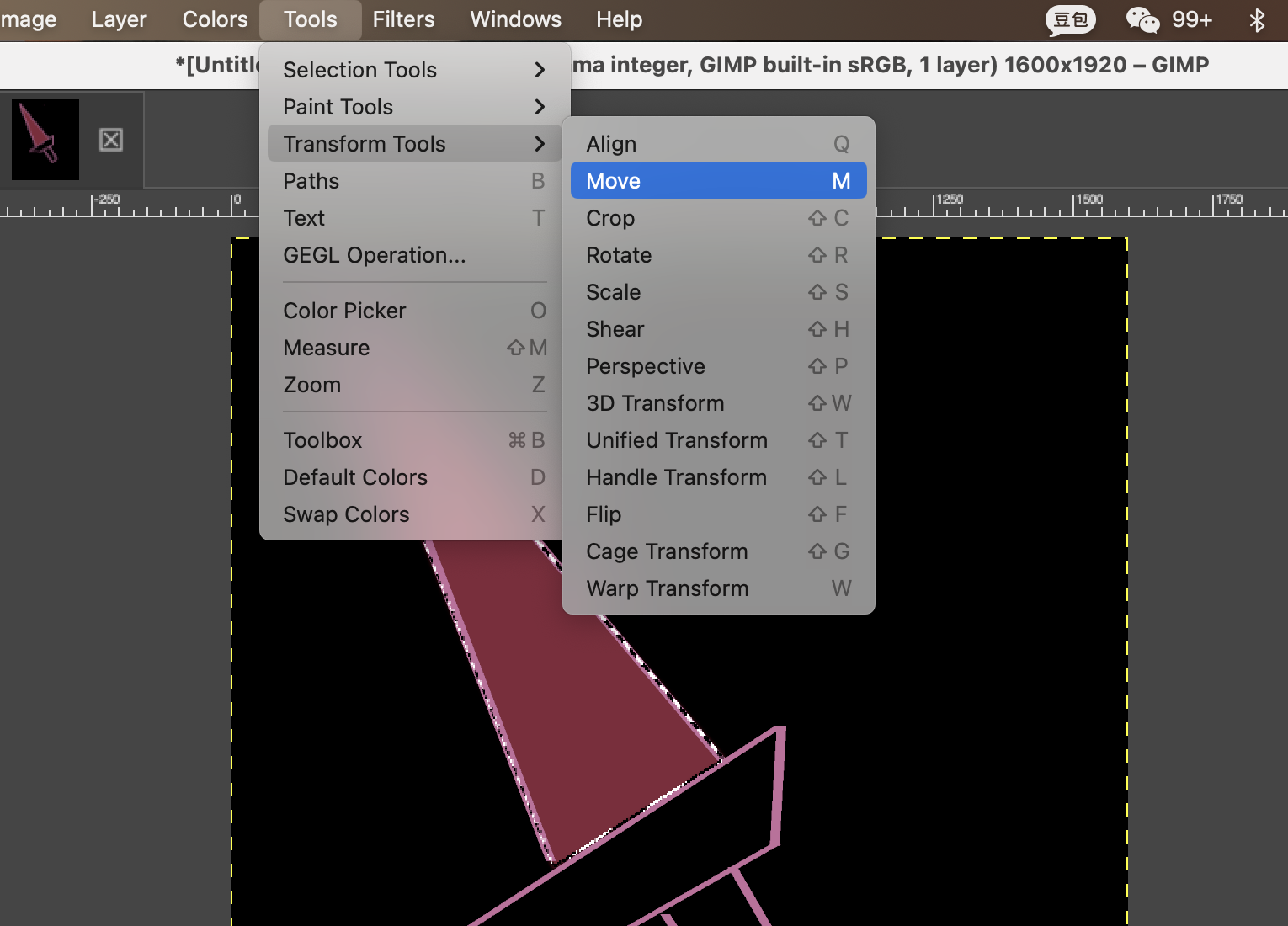
Move the free selected part and painted another color
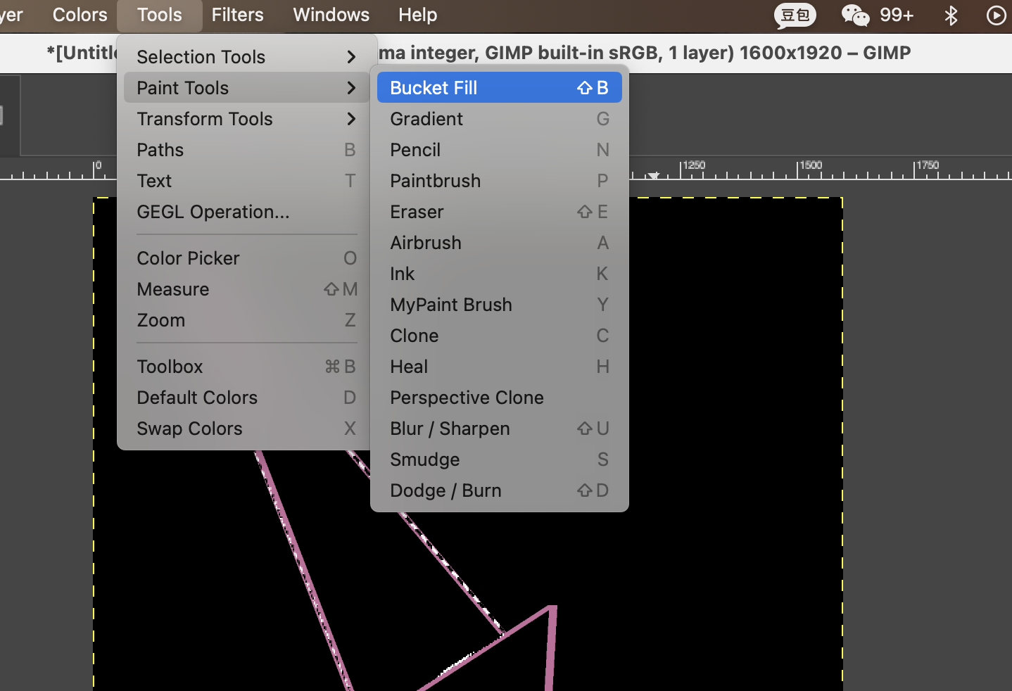
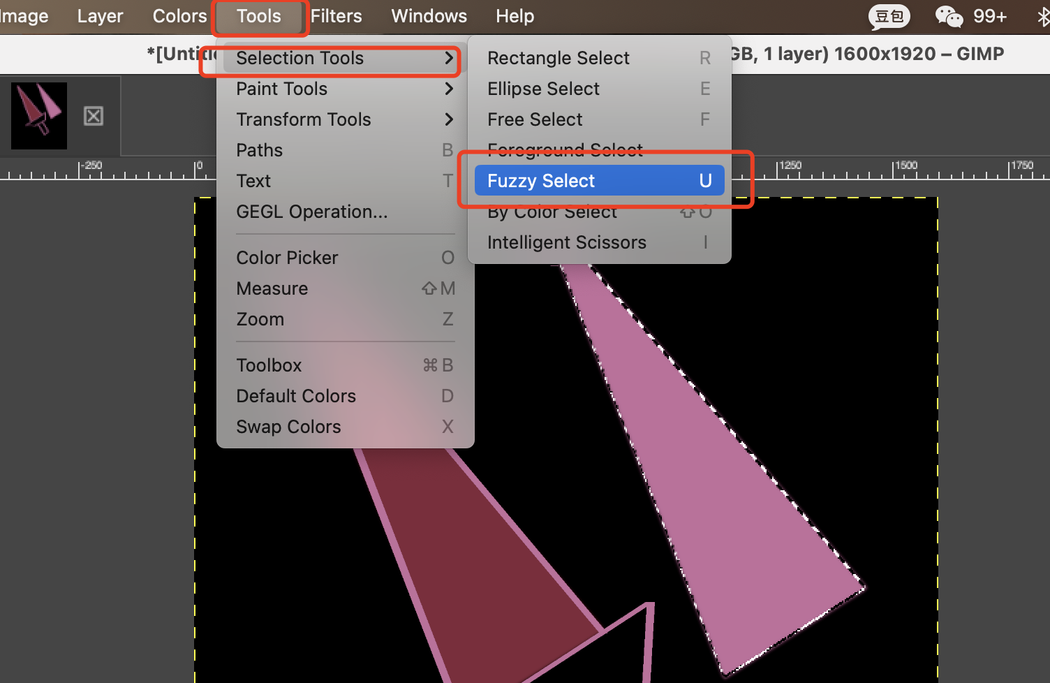
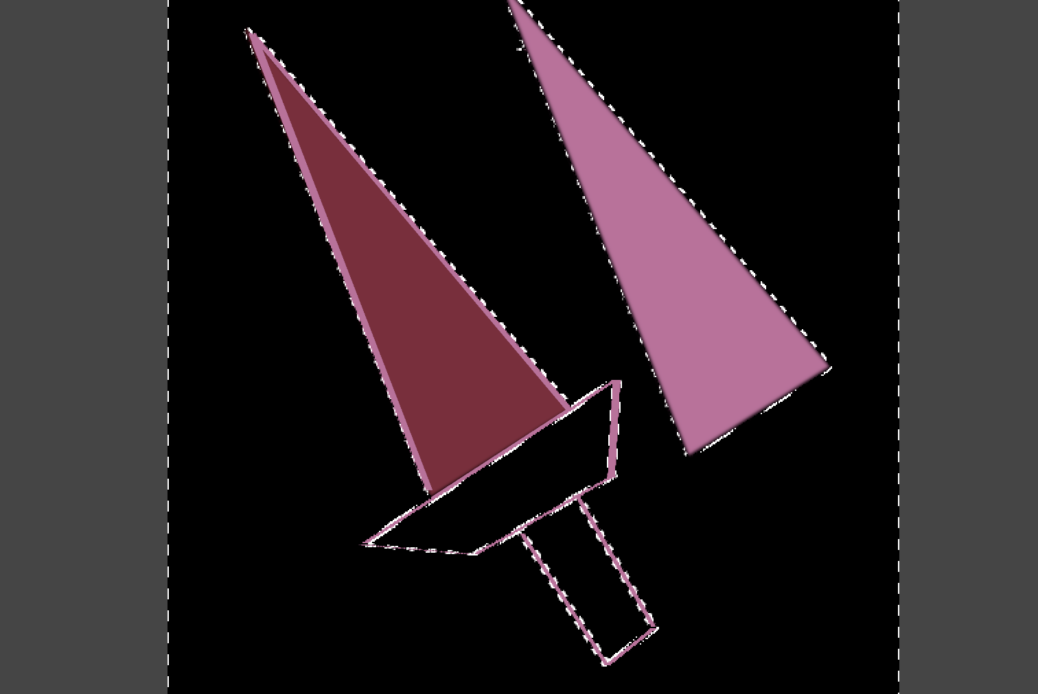
06 Try the Tools->Selection Tools ->Fuzzy Tool
The fuzzy tool is very simple, just click on the point in the area, then the whole area is selected
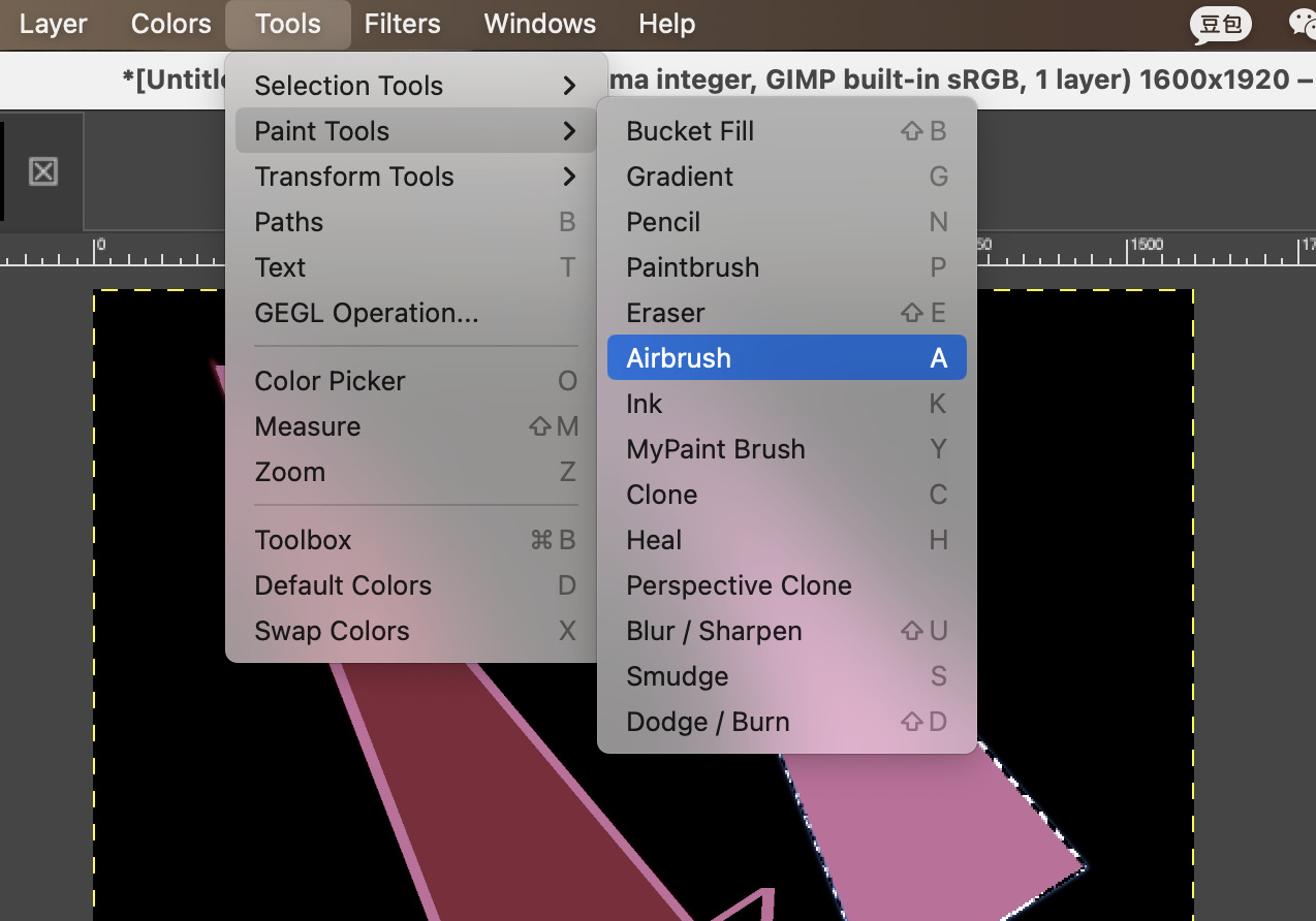
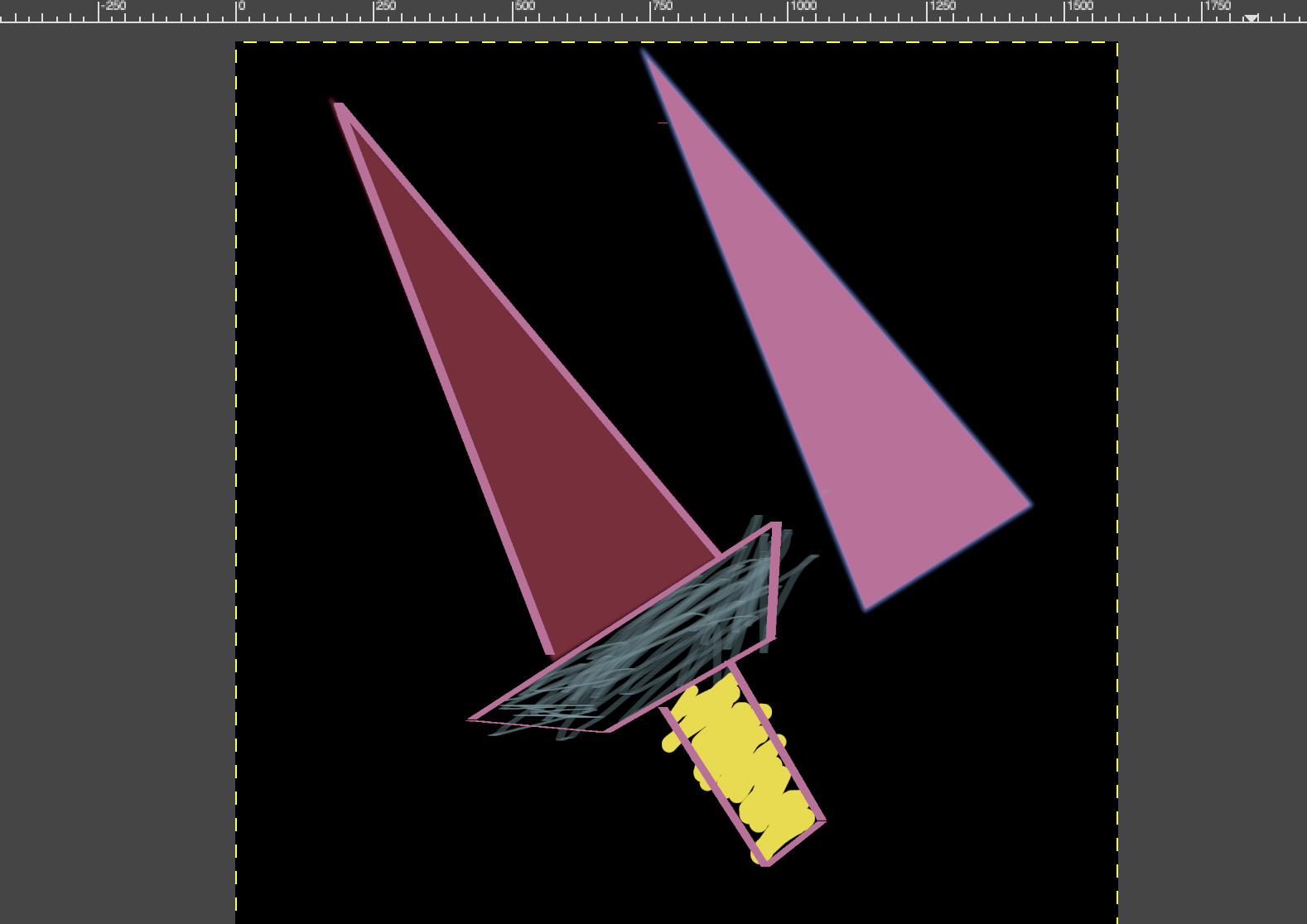
06 Try AirBrush, Tools->PaintTool->Air Brush
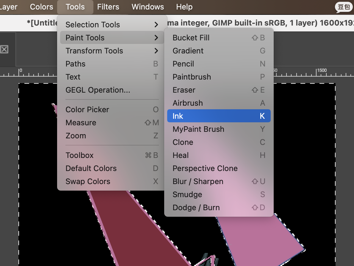
07 Try Ink PaintTool, Tools->PaintTool-InkPaint
2D Design - InkScape
Personally, based on my limited knowledge of 2D and 3D design, I think that when working with 3D software, vector images may be more convenient.
01 First, use the shape command in the left panel to create some basic shapes.
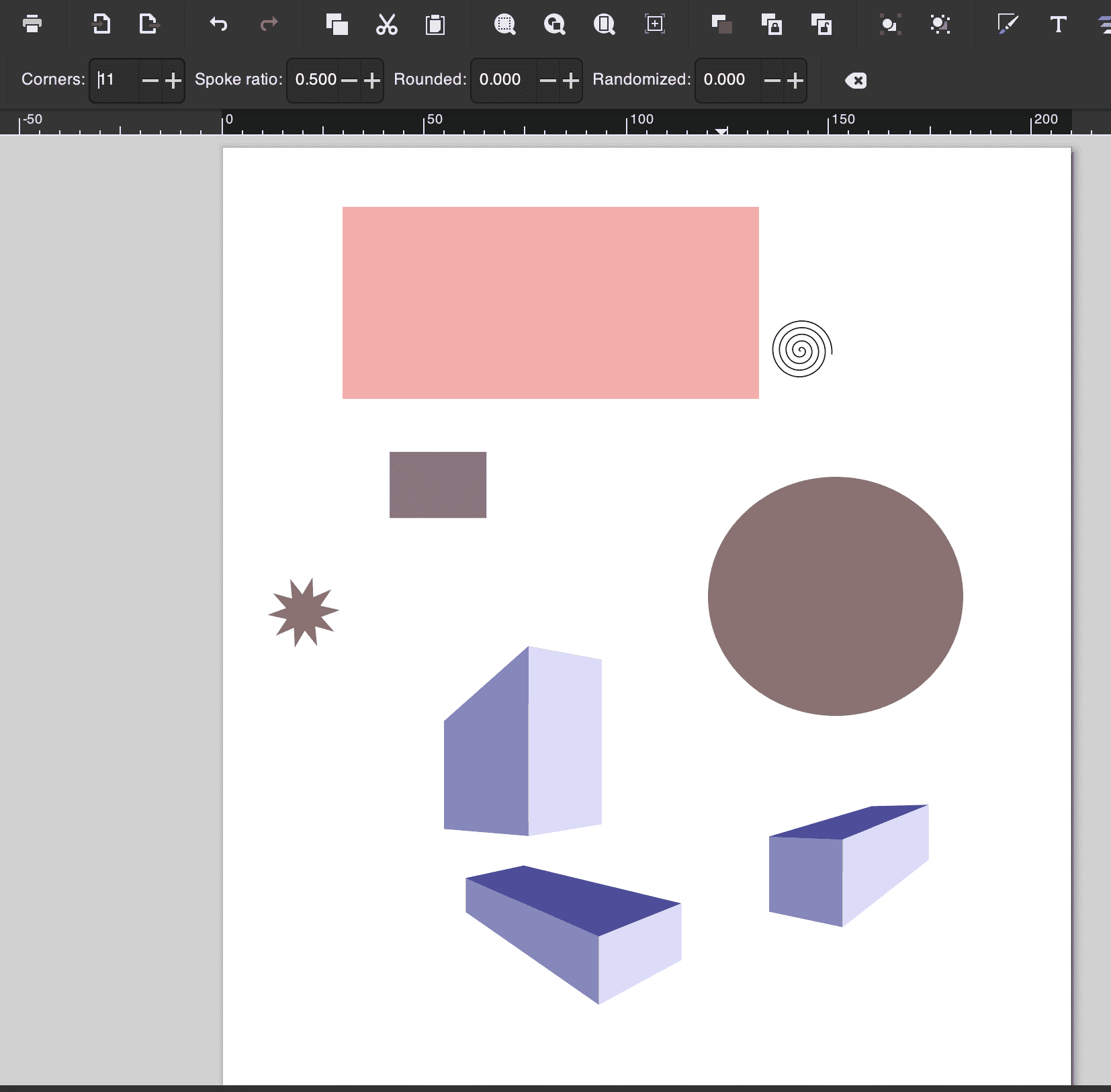
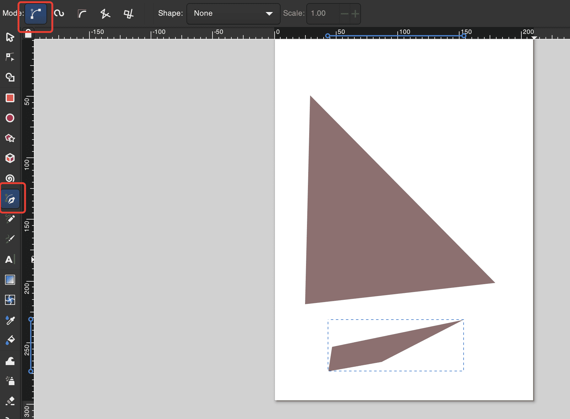
02 Then I started trying to use the pen and pencil in different modes to check the various drawing effects.First attemp using pen with rectangle path:
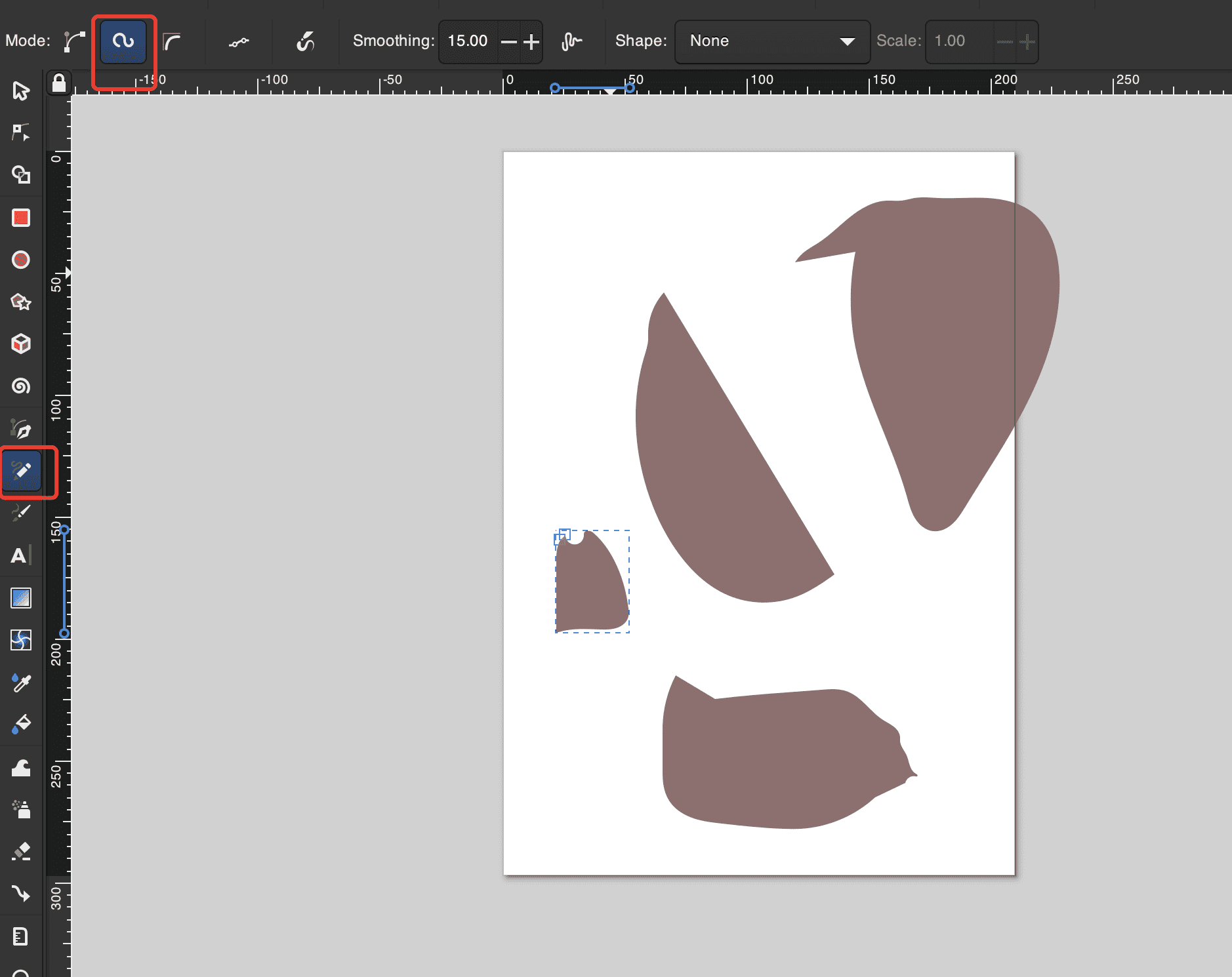
03 Second attempt using pencil with spiro path. It turns out like free drawing
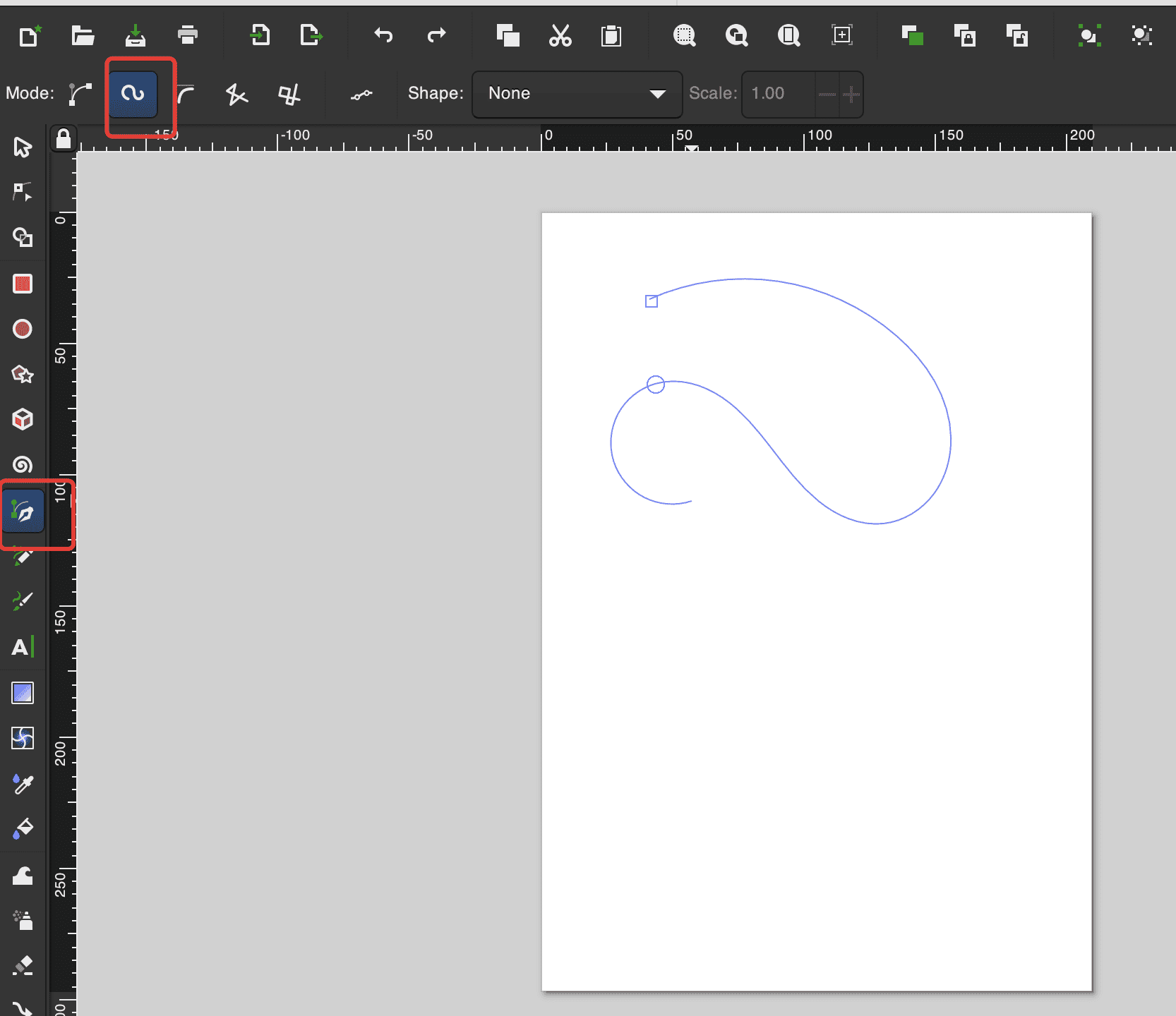
04 Third attempt using pen with spiro path:
05 The final output of the third attempt looks like a neck pillow used for travelling
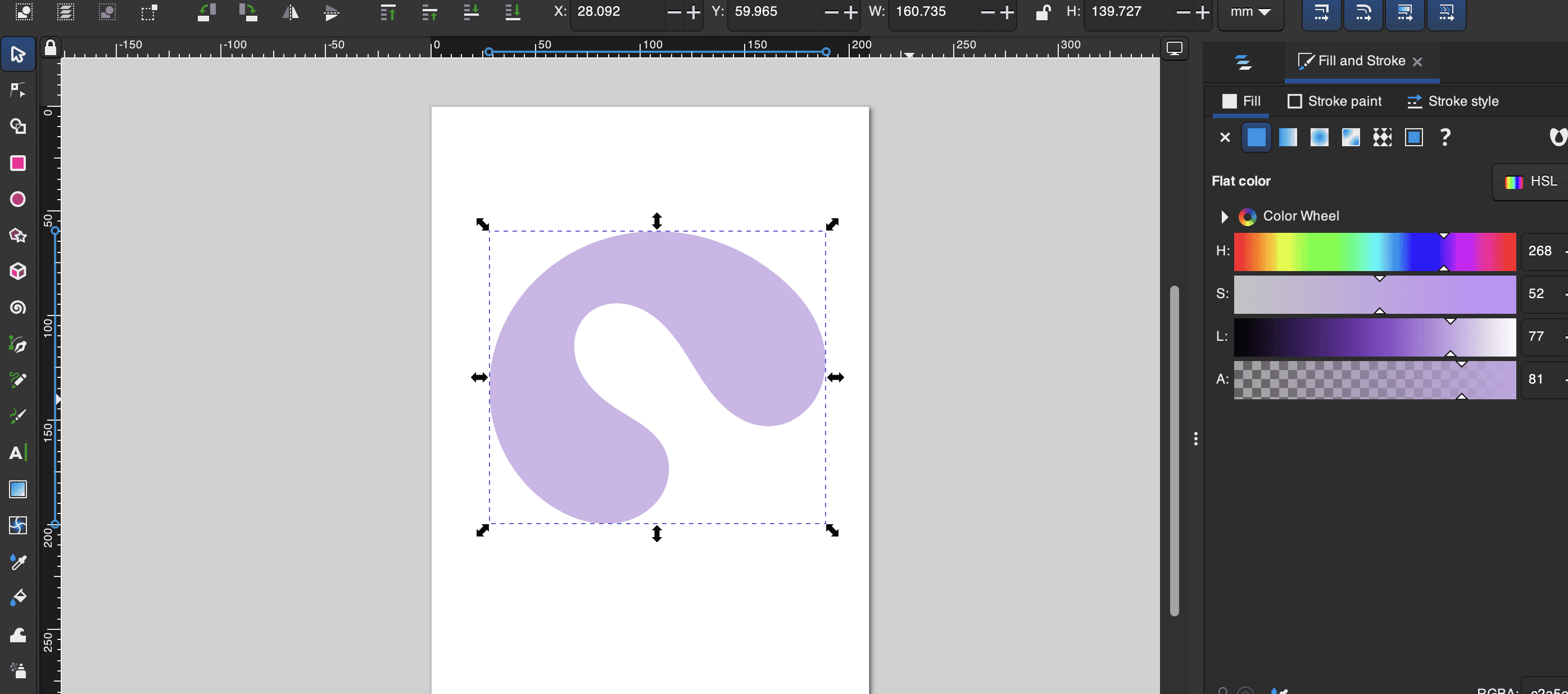
06 Finally, I tried cutting some shapes inside the original shape using the path-difference tool.
3D Design - Fusion 360
For this part, I am going to introduce my procedures for making the sword blade part using Fusion 360.
Step1 Draw your design on paper
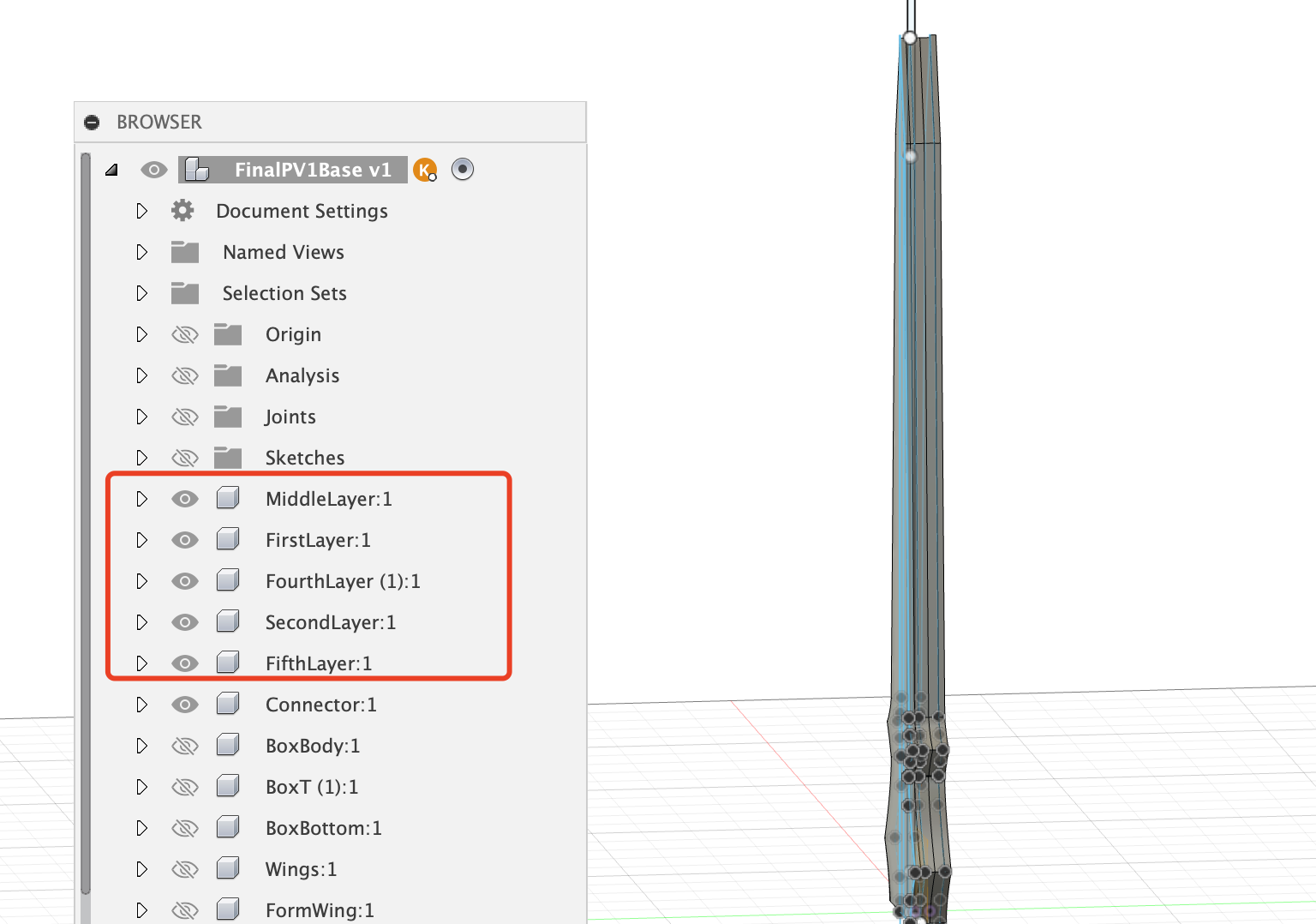
My blade will include 5 layers.
The first and fifth layers will be the same. The second and fourth layers will be the same to put the LED inside, and the middle layer will be used for connection.
Step2 Divide design into components
It is highly recommended that before the design, you have a very clear plan about how your whole design could be divided into different components, based on their structural faces.
I have divided my design into five components for each layer.
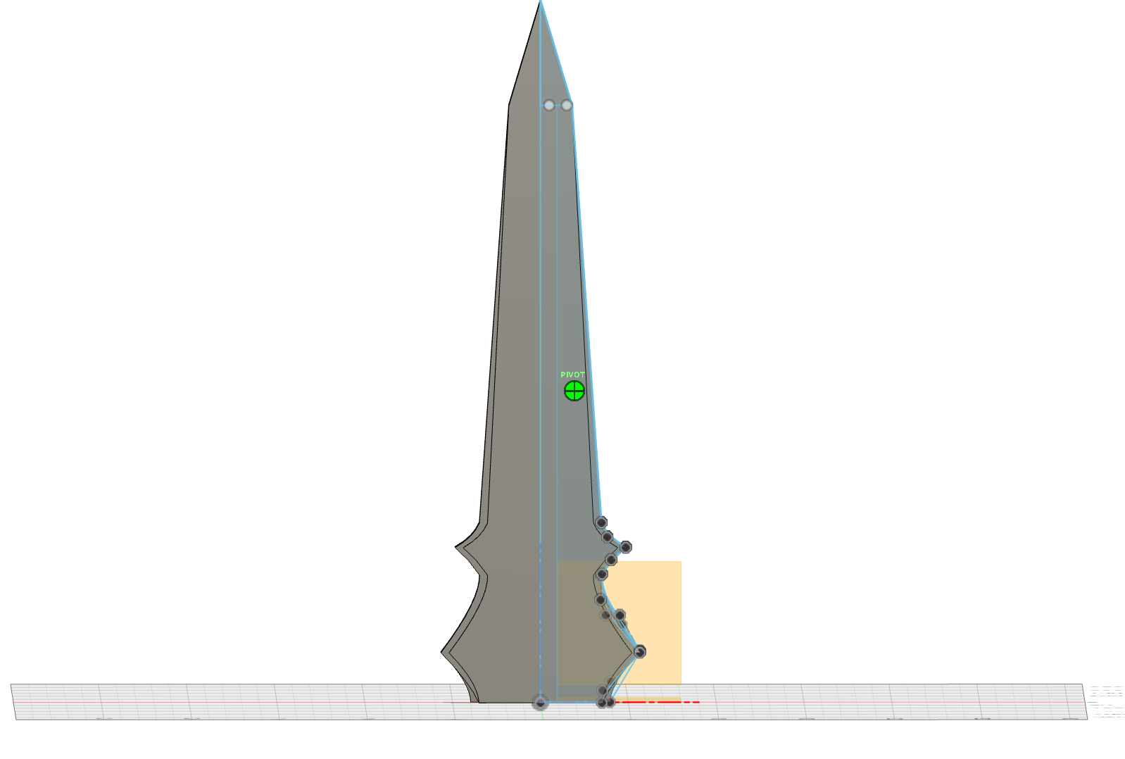
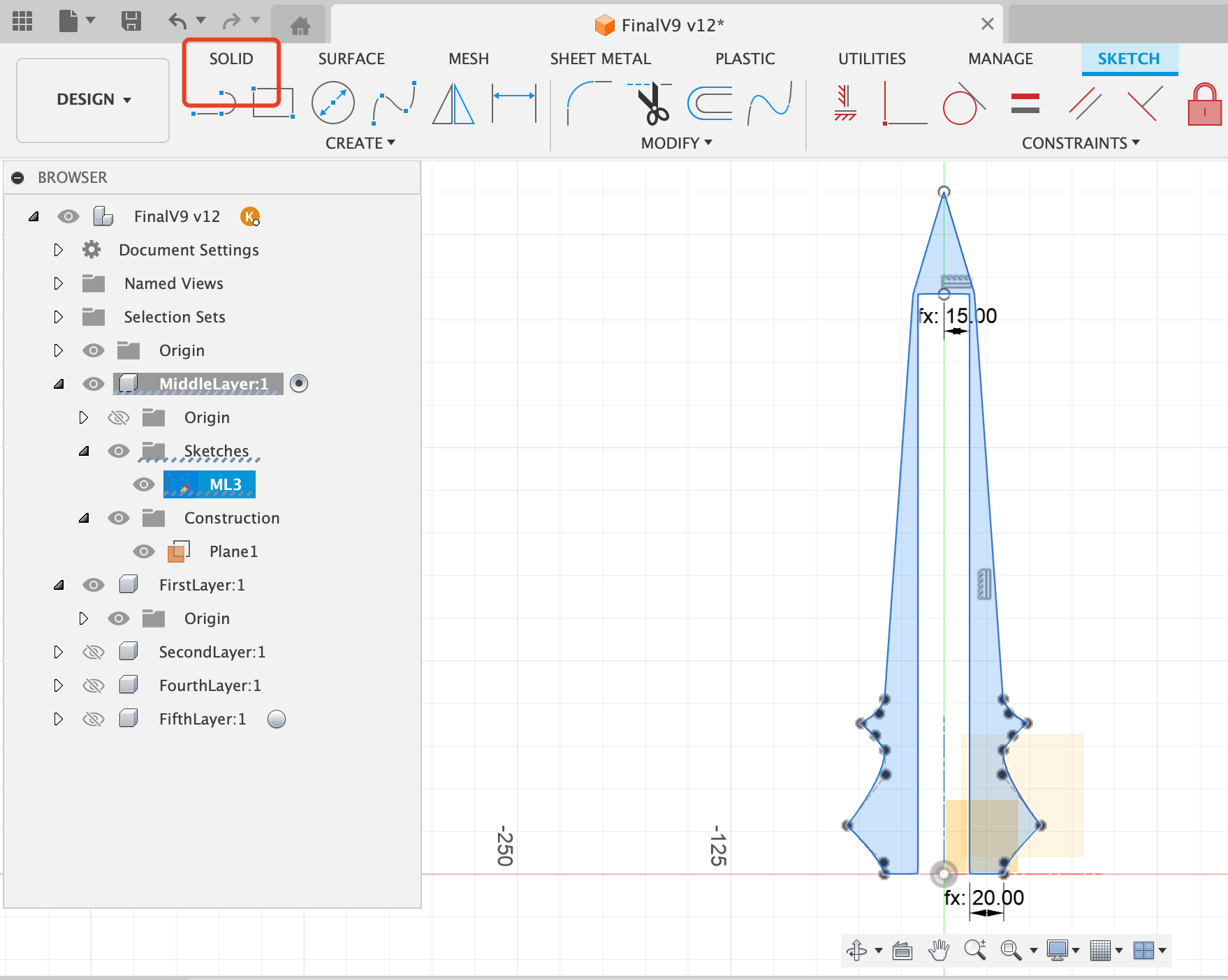
Step3 Create the schetch for the first componnet
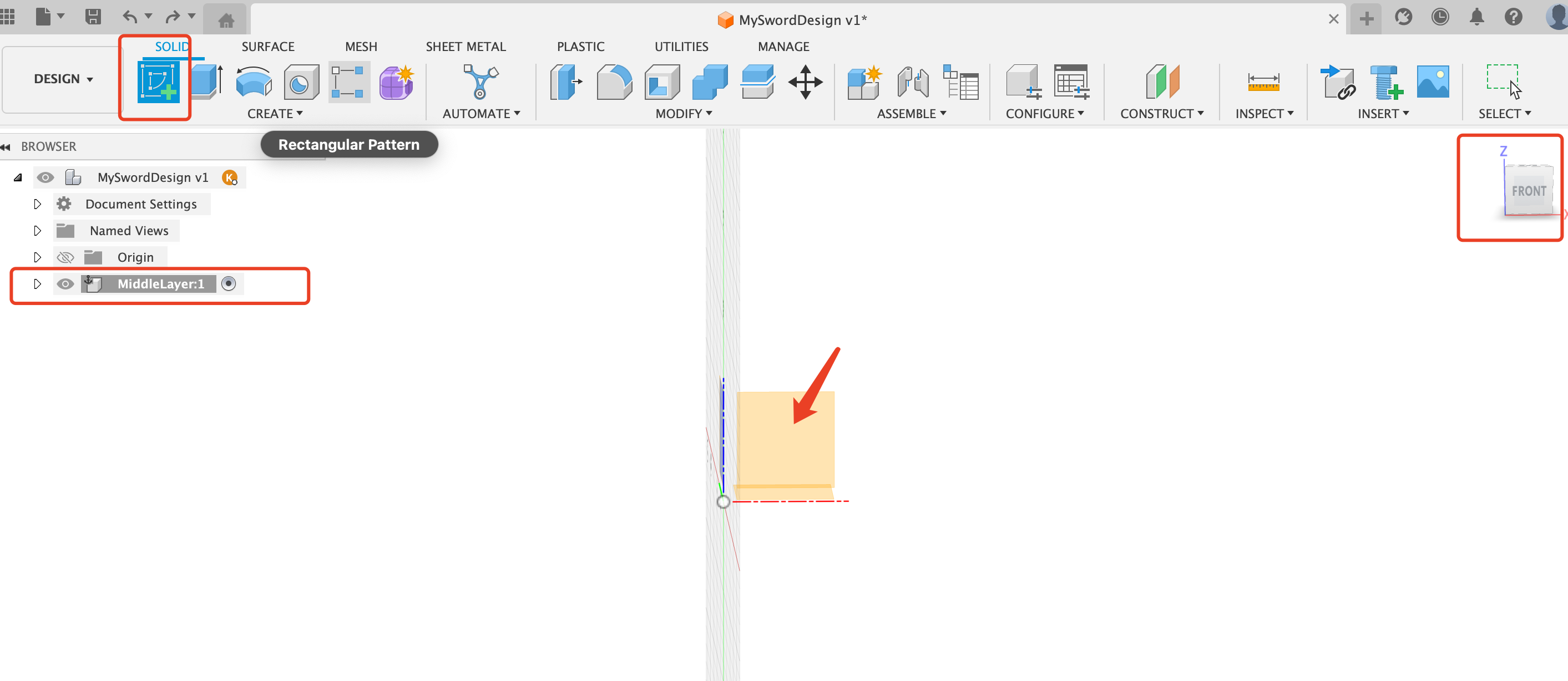
It is recommneded to create the first component on the base origin plane.
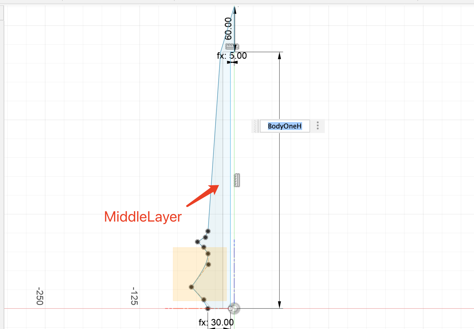
For my case, the first component to put on the xz plane is middle layer.
Create Design First
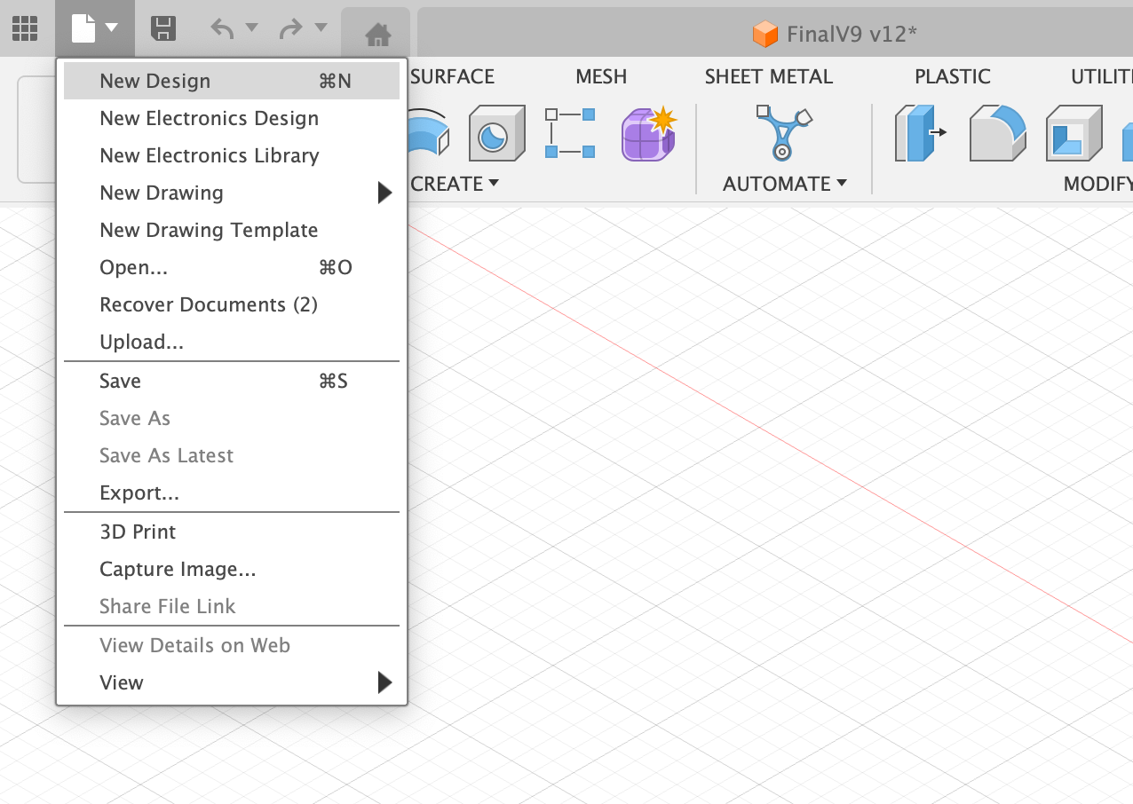
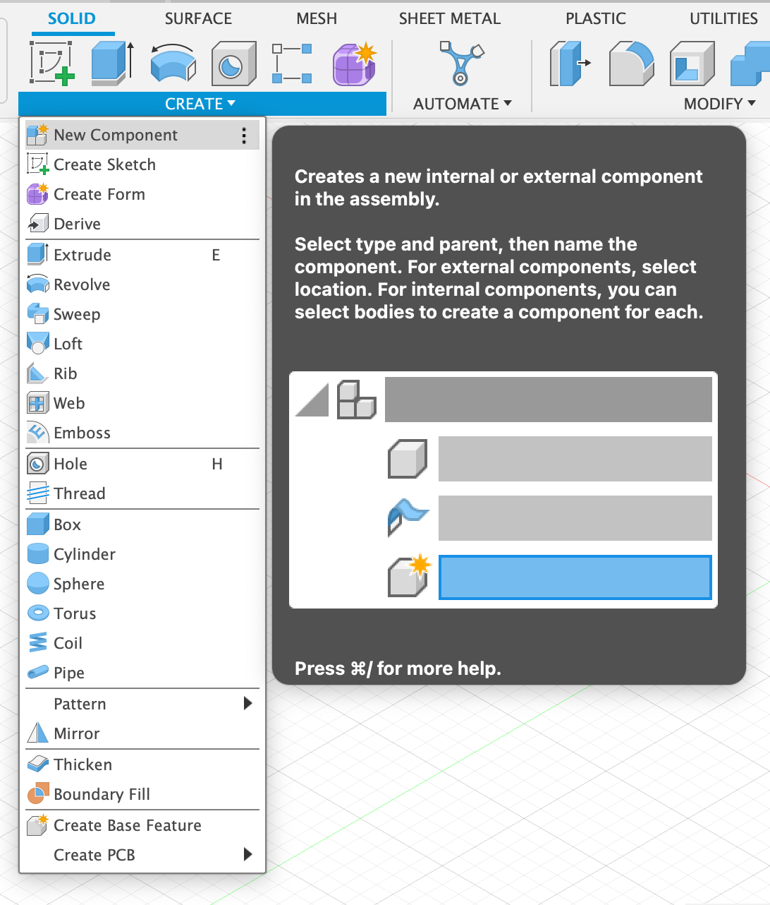
Then Create the Component
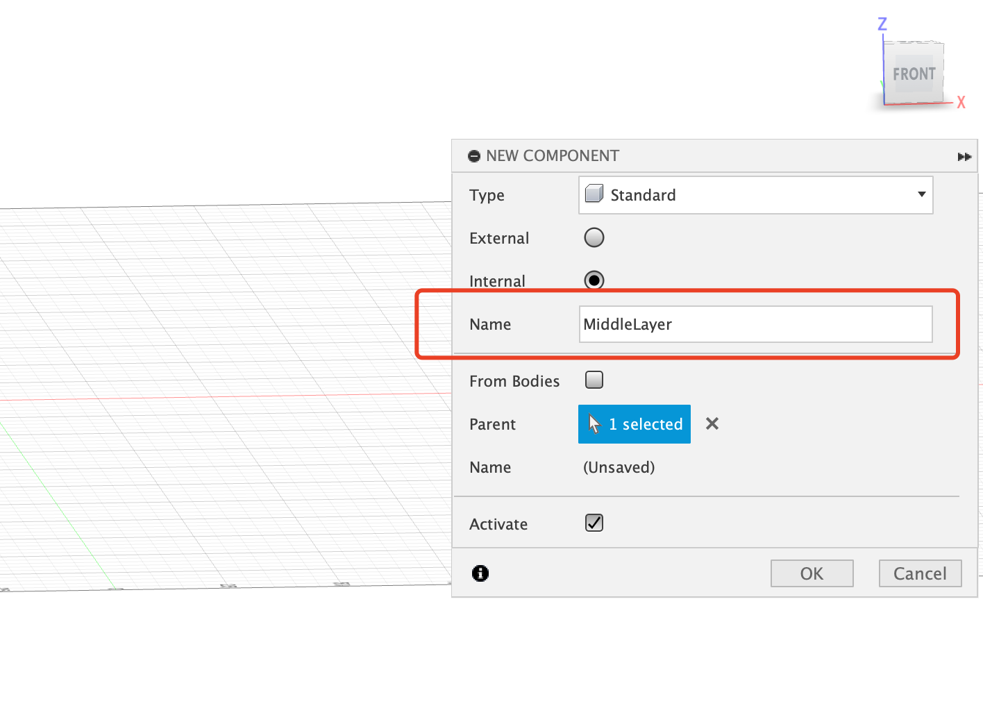
Then Use the Orbit to adjust the plane view and Create the Scketch on the XZ plane
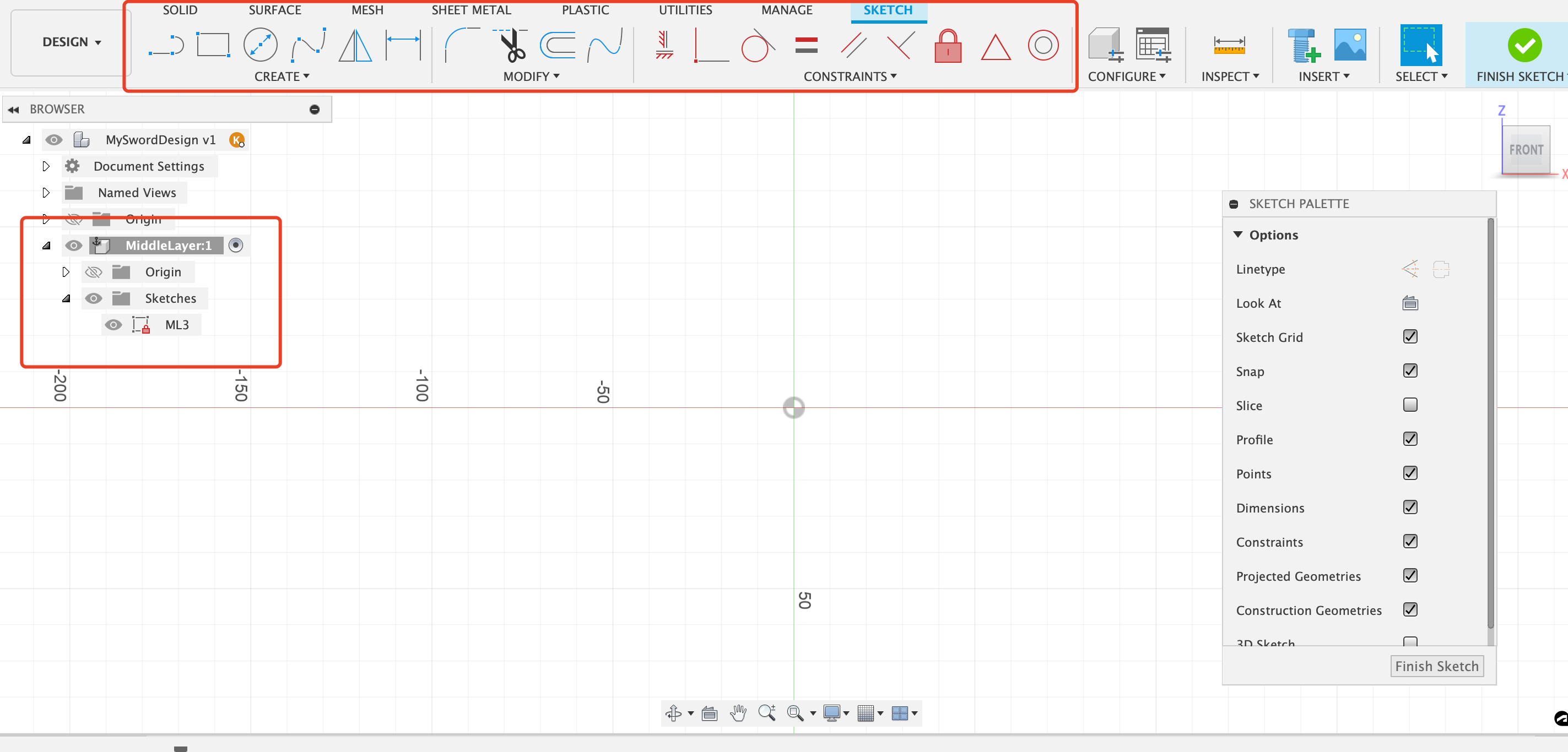
Set up Parameters
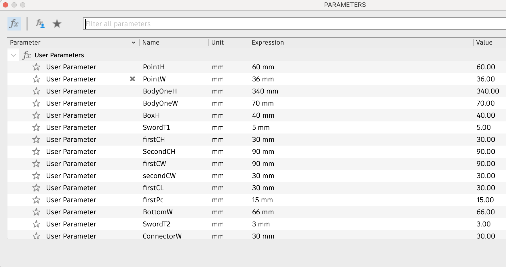
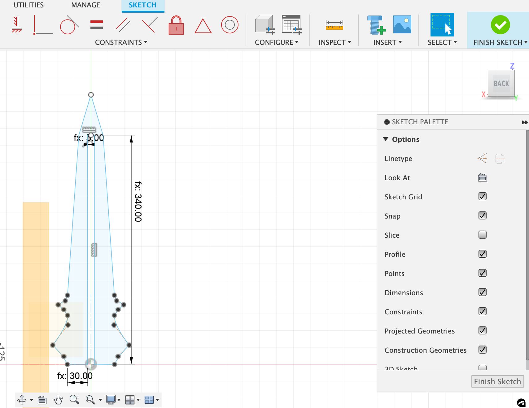
Draw lines and shapes using the tools above, and apply the parameters to the lines.
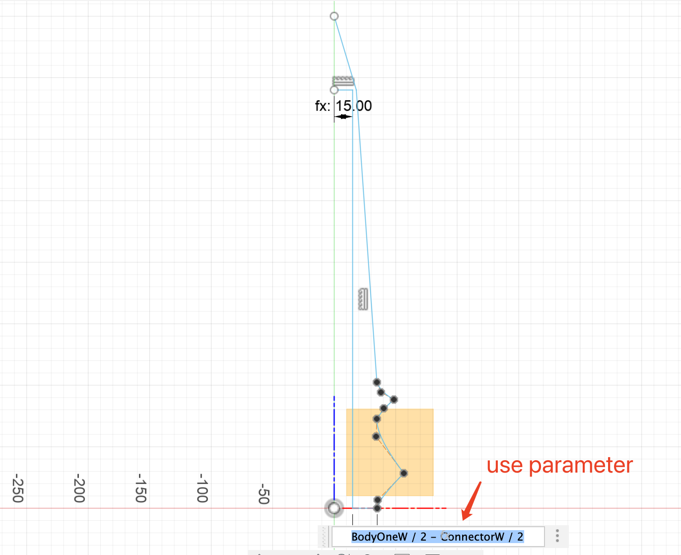
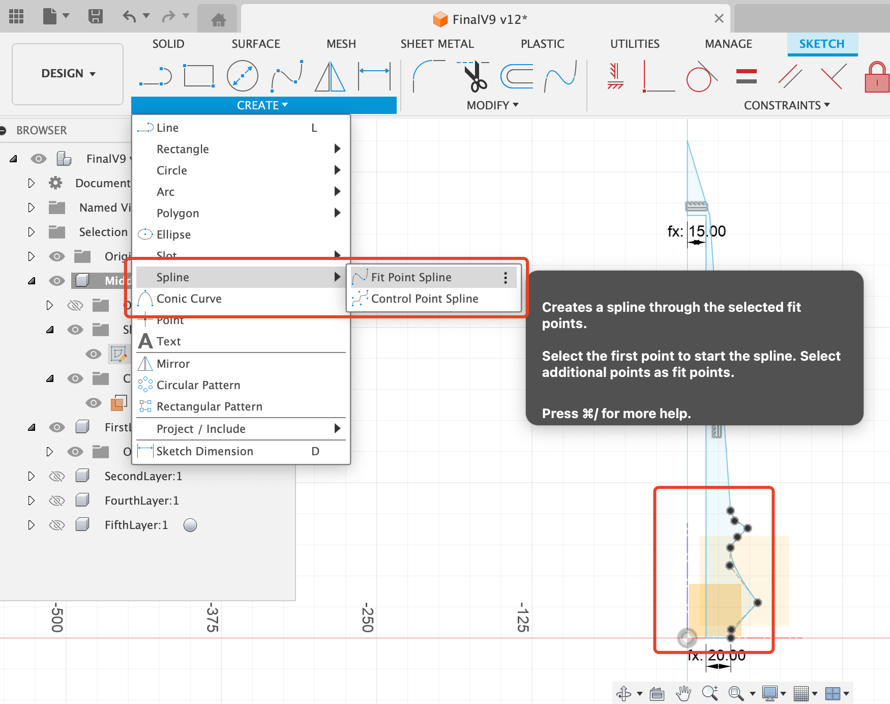
You can also use the spine tool to draw curving lines.
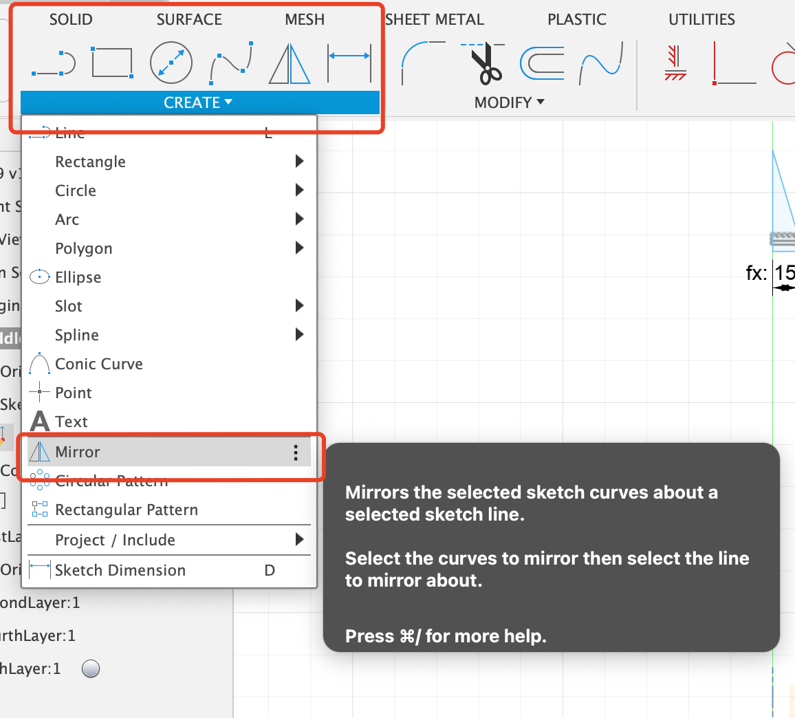
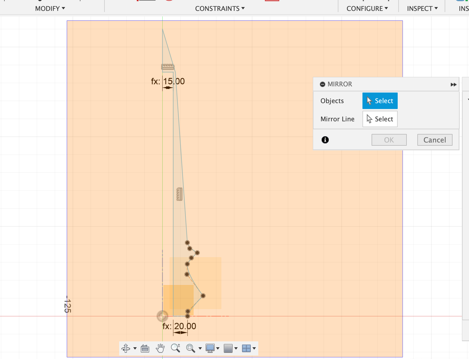
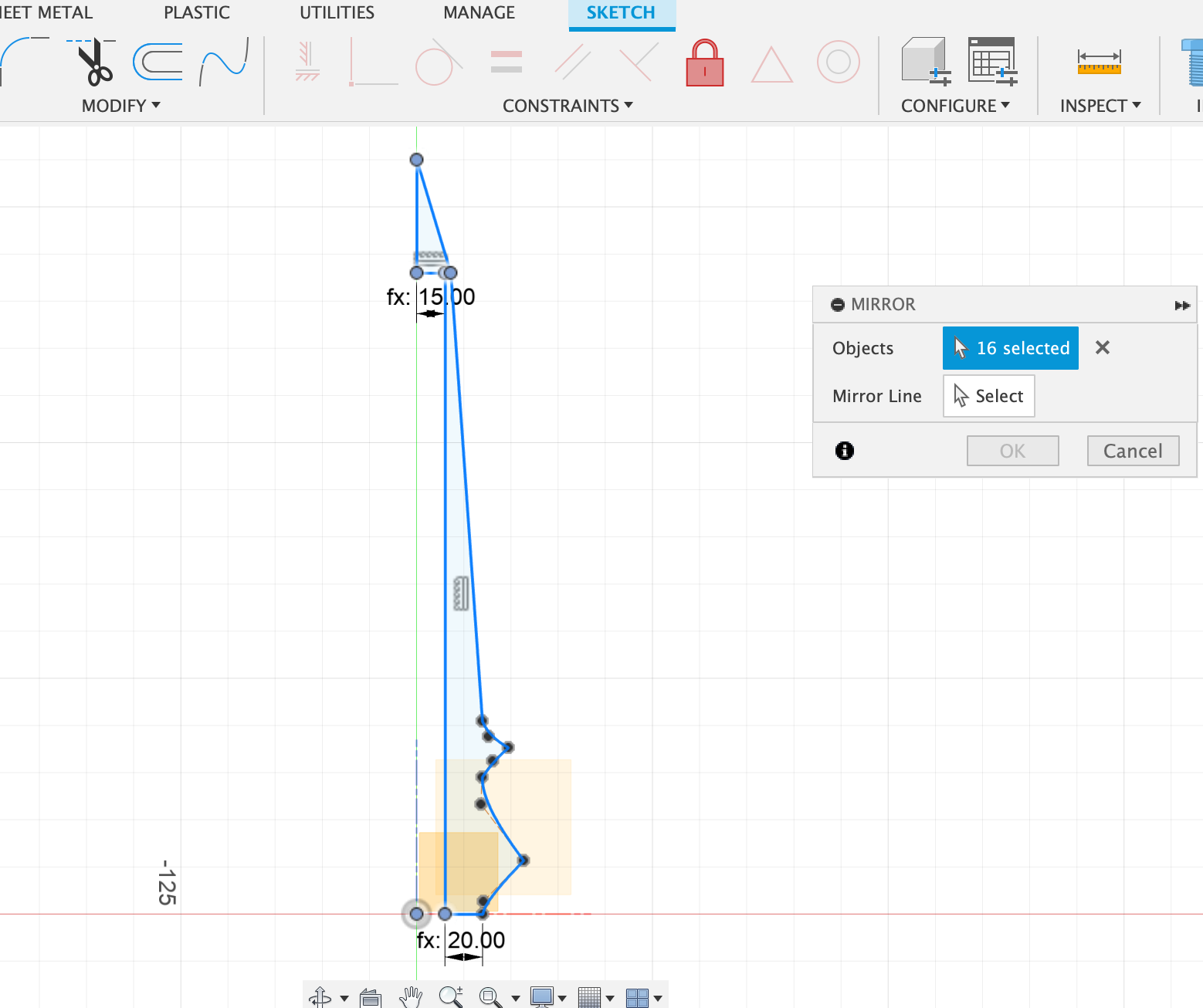
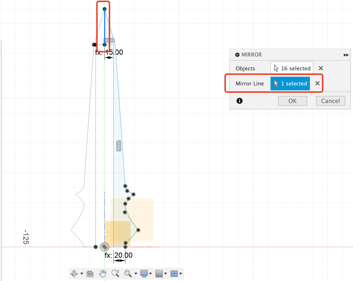
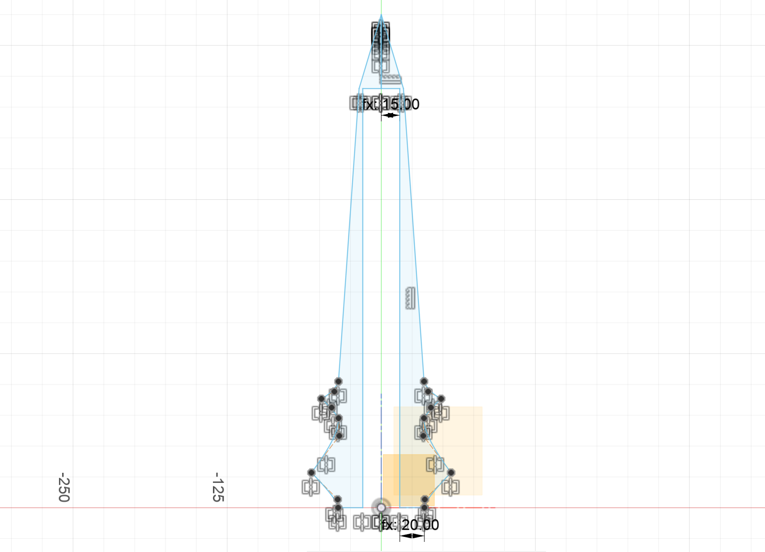
Another very useful tool is "Mirror"
Simply slide your mouse, and you can select all the lines.
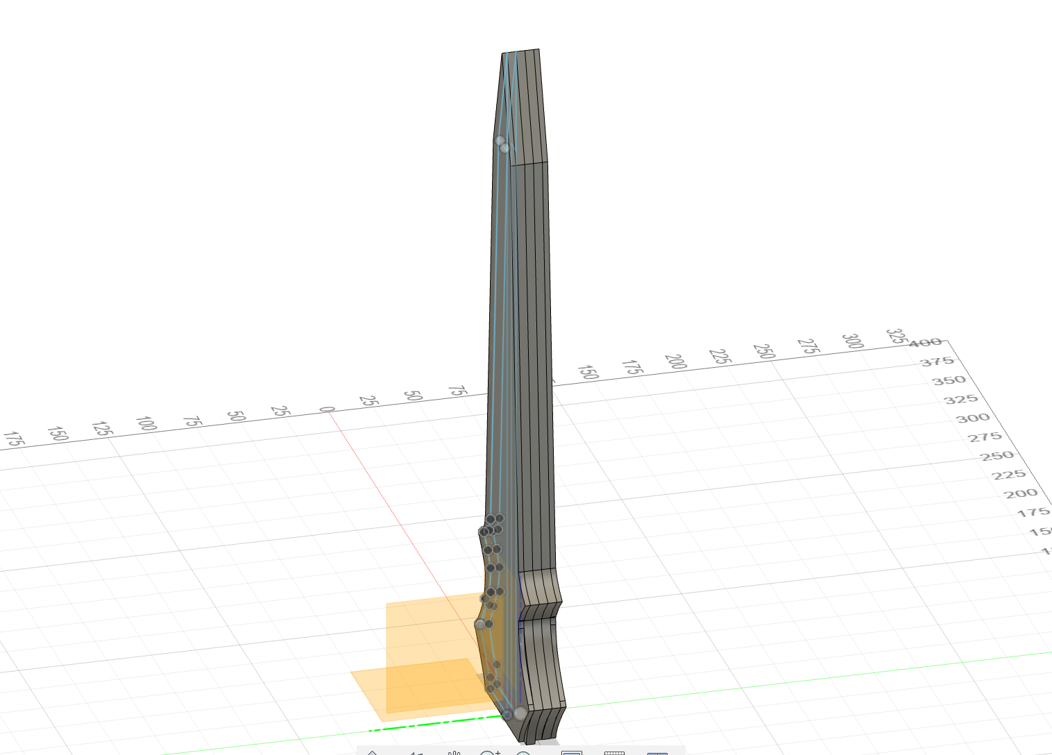
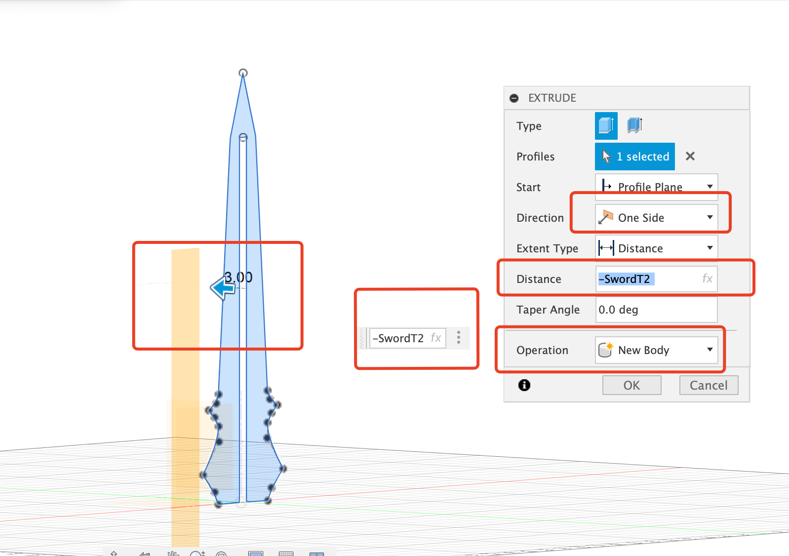
Step 4: Extrude the sketch to create a solid body
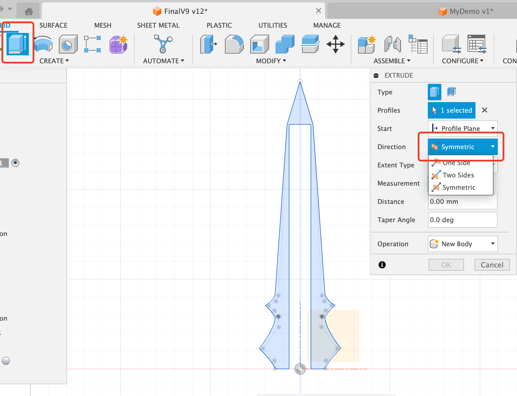
When you extrude, there are three important options: the direction, the distance, and the operation
Direction:
The direction option determines the orientation in which the sketch is extruded. The main options are:
One-Sided: Extrudes the sketch in a single direction, either positively or negatively, perpendicular to the sketch plane.
Two-Sided: Extrudes the sketch in both the positive and negative directions, perpendicular to the sketch plane.
Symmetric: Extrudes the sketch symmetrically in both the positive and negative directions, perpendicular to the sketch plane.
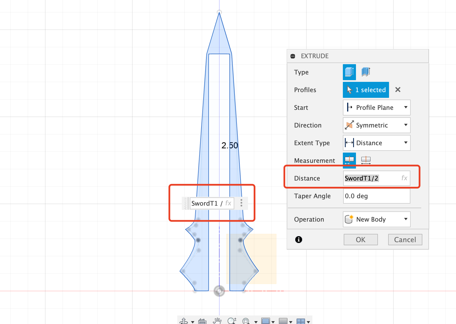
Distance:
The distance option specifies how far the sketch should be extruded. This can be set by inputting a specific numerical value, which can be either positive or negative:
Positive Distance: Extrudes the sketch in the positive direction, away from the sketch plane.
Negative Distance: Extrudes the sketch in the negative direction, towards the sketch plane.
Operation:
The operation option determines how the extruded body should be combined with the existing geometry. The main options are:
New Body: Creates a new, separate body from the extruded sketch.
Join: Joins the extruded body to the existing bodies, merging them into a single solid.
Cut: Cuts away material from the existing bodies based on the extruded sketch.
Intersect: Creates a new body that is the intersection of the extruded sketch and the existing bodies.
For my case, the middle layer needs to be extruded symmetrically, and the distance should be the total thinkness divided by 2
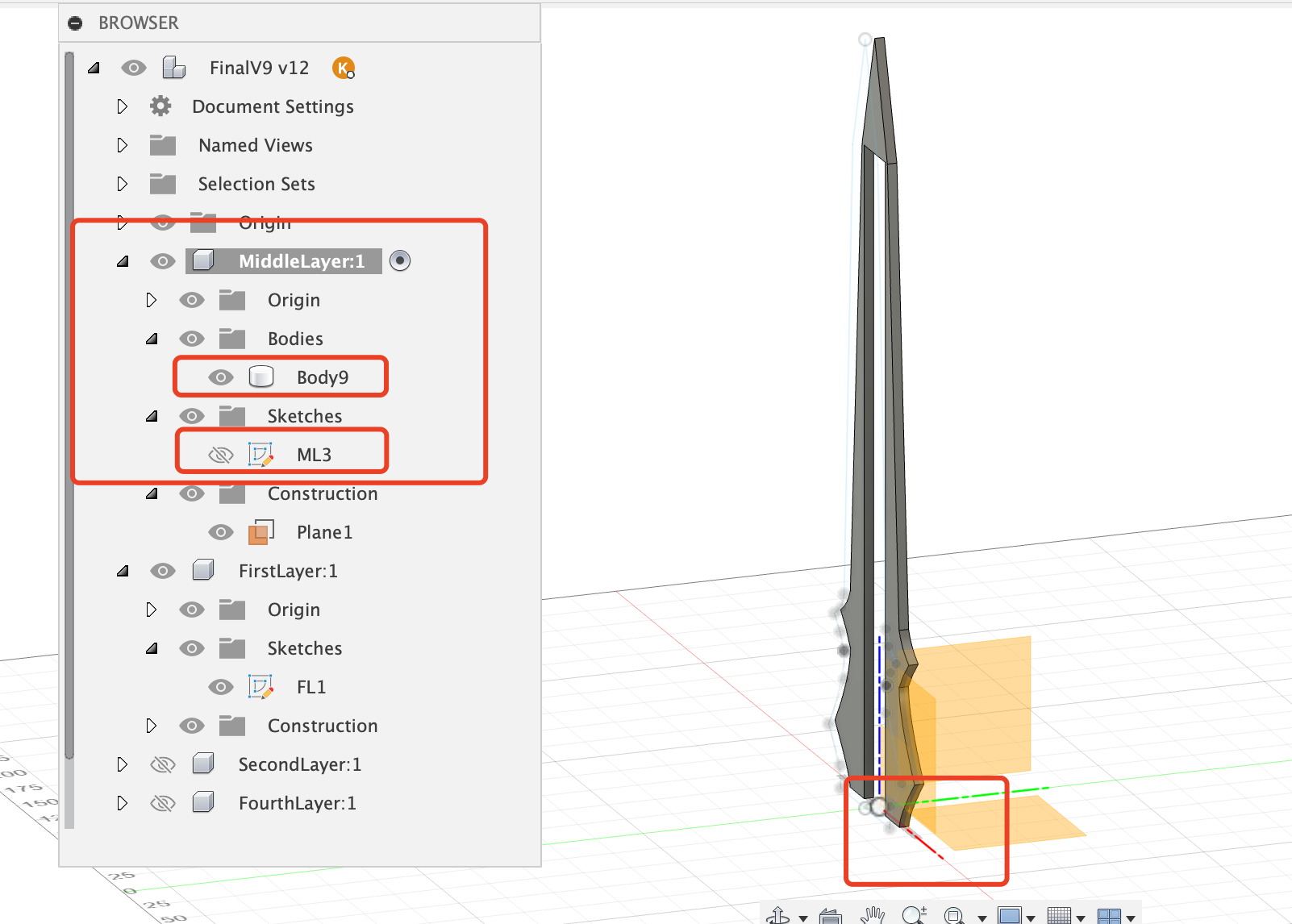
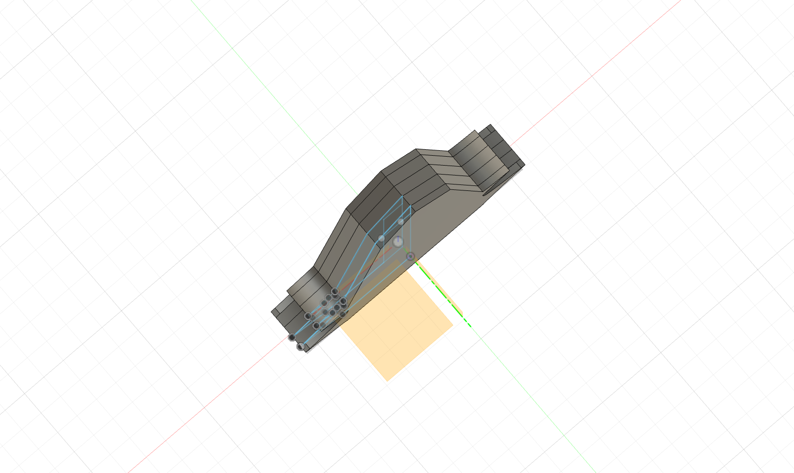
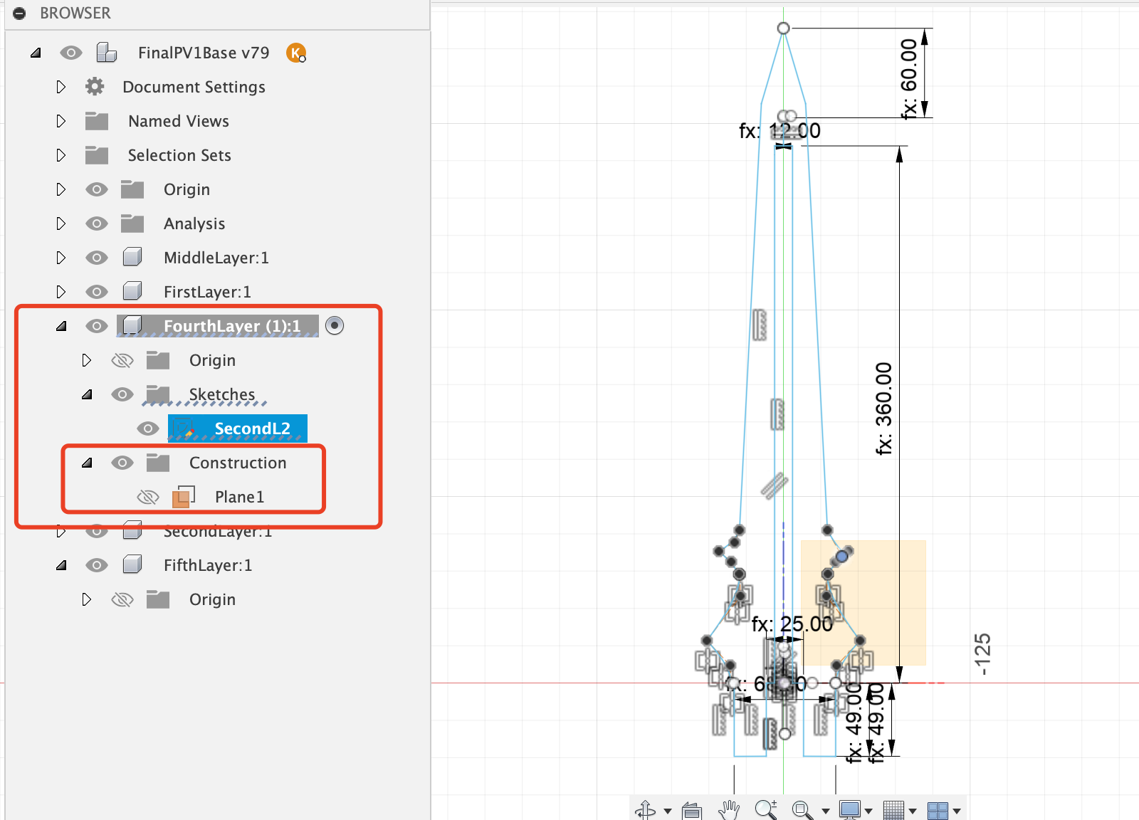
Step 5: Create Second Layers
The layers adjacent to the middle layer are the second and fourth layers, and their designs are also the same, to be used for placing the LED strip.
- So firstly, create a component for second layer.
- Secondly, because the second layer won't be on the same plane as the middle layer, the offset plane needs to be set first.
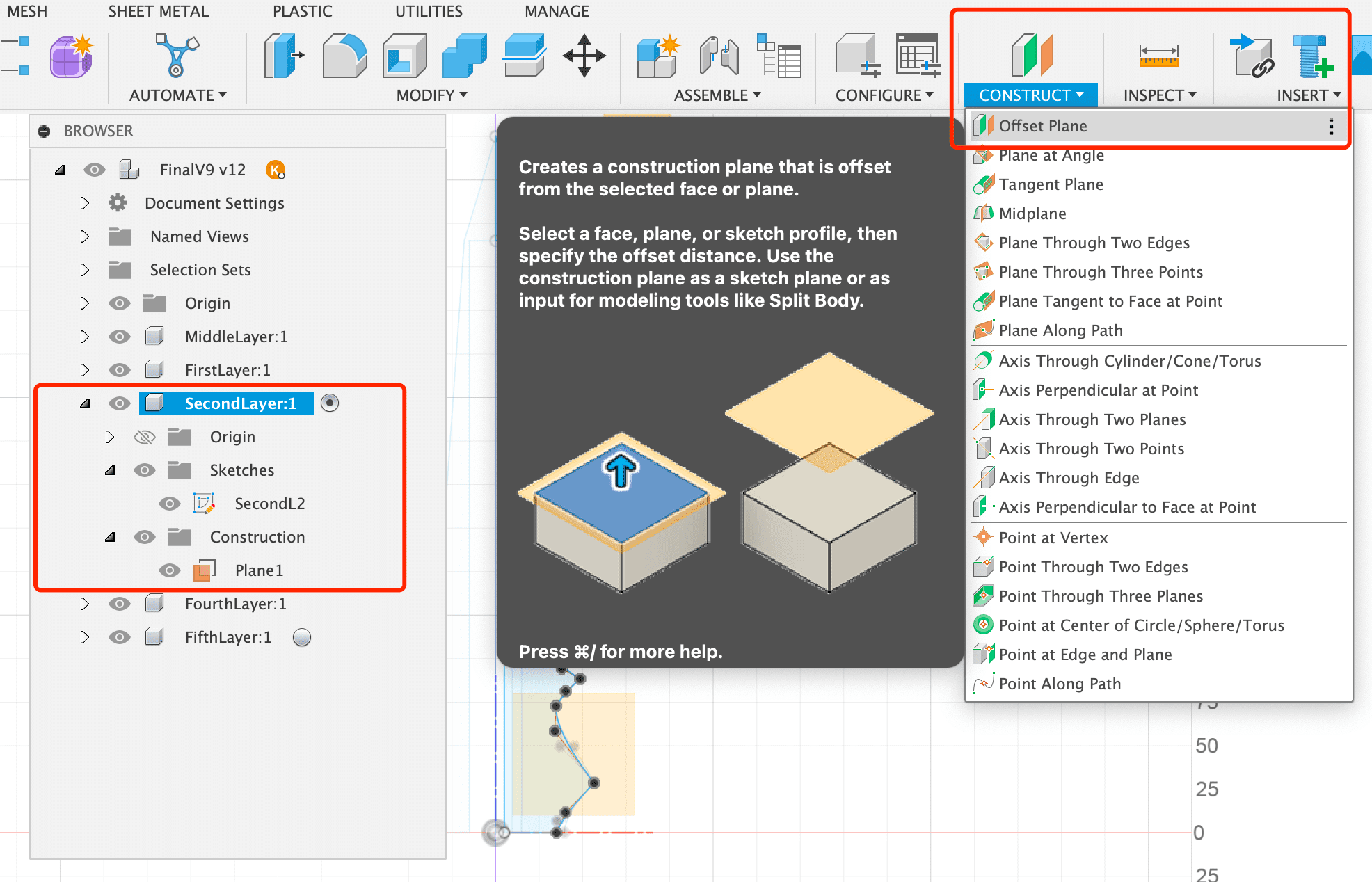
- Thirdly, calculate the offset distance from the reference plane, and set the position of the new plane
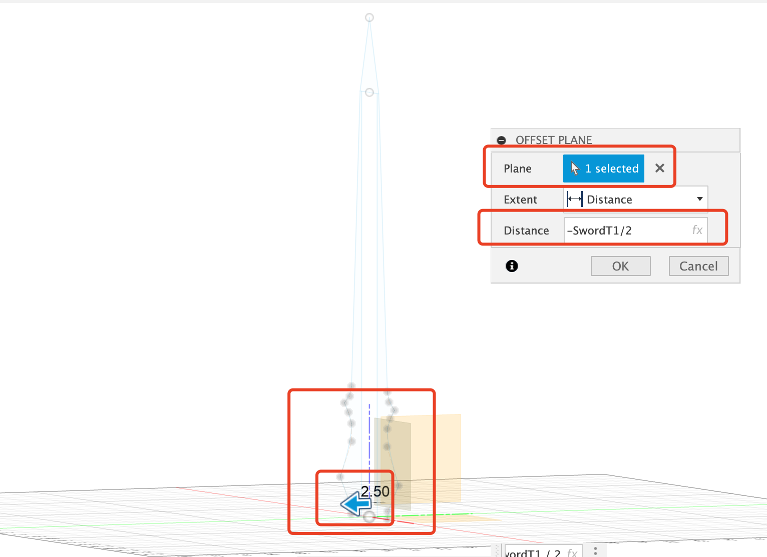
- Then, create the scketch on the offset plane
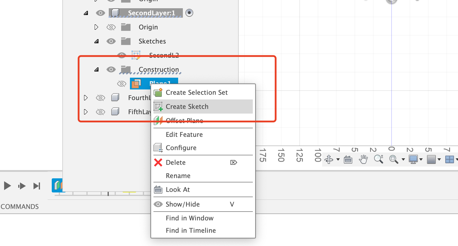
- Then, create the sketch on the offset plane.
Since the second layer is used to hold the LED light strip, its middle gap is much smaller than the middle layer.
When drawing the sketch, you can also see the sketch of the middle layer, which is convenient for alignment.
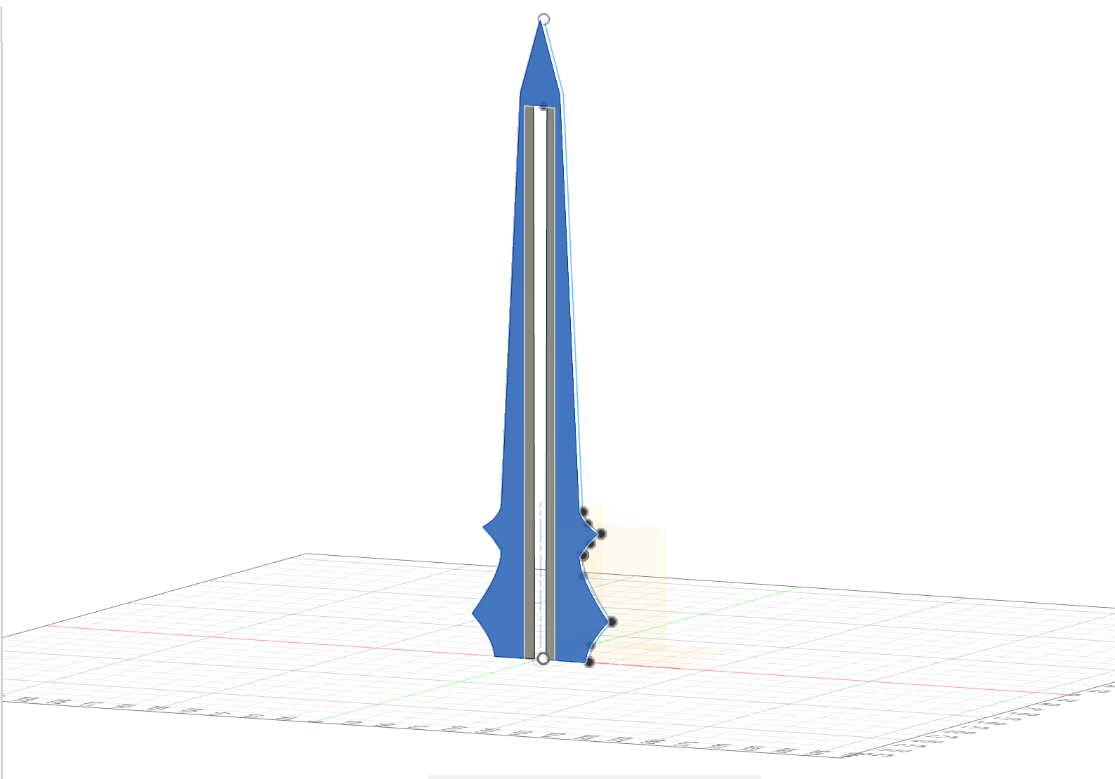
- Extrude the second layer,and this time I will use One-Sided .
- Two layers extruded.
- Fourth layer is almost the same as second layer,but on different plane
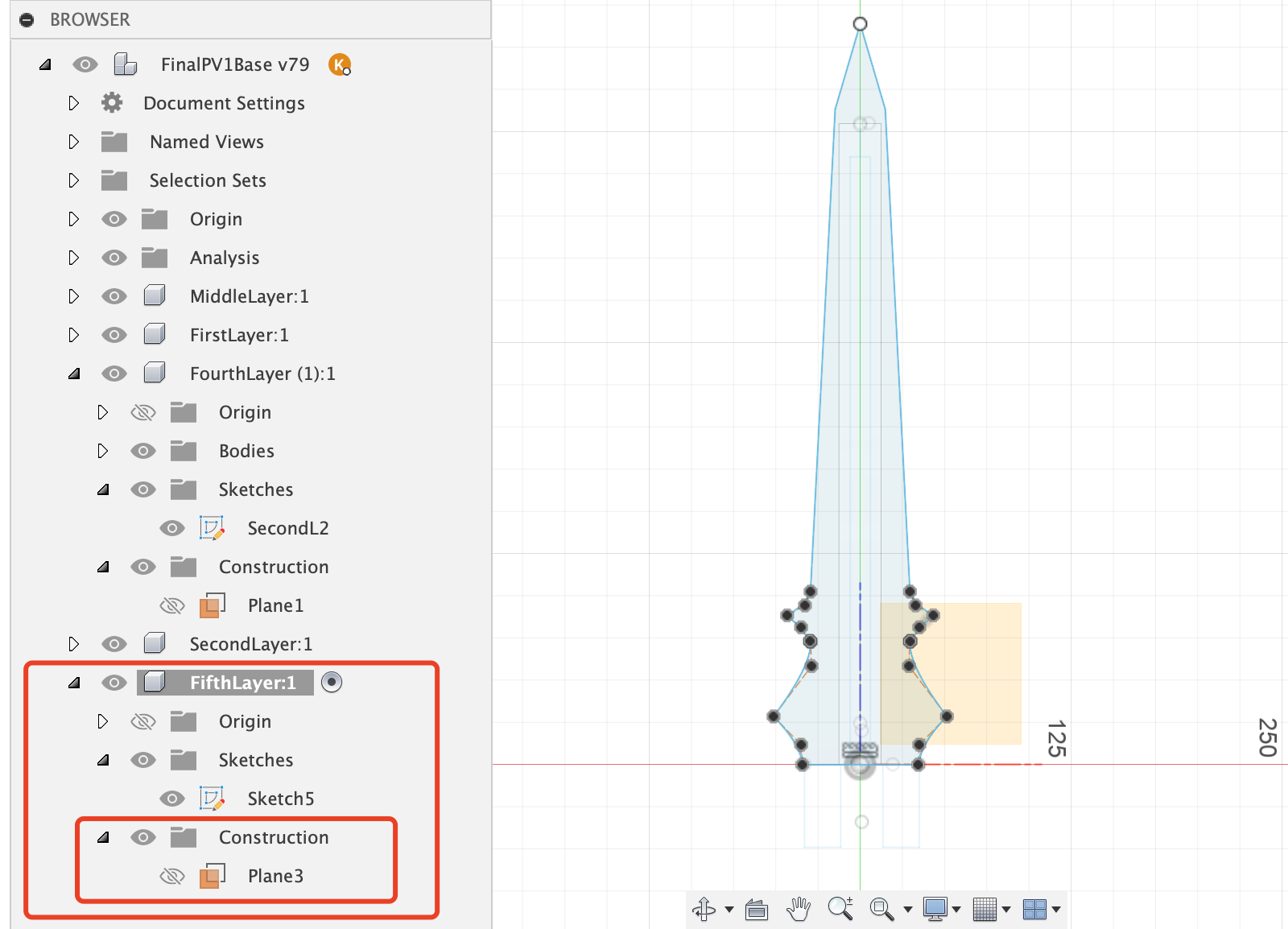
Step 5: Create Fifth Layer
The fifth layer and the first layer are the same - they are both the outermost enclosure layers.
There is no need to leave any gaps in the middle, just like the second layer and the fourth layer.
You need to first calculate the offset plane, and then create the sketch on the offset plane.
Step 6: Extrude all five layers