Weekly assignments
- week 1. Project Management
- week 2. Computer Aided Design
- week 3. Computer Controlled Cutting
- week 4. Electronics Production
- week 5. 3D Scanning and Printing
- week 6. Embeded Programming
- week 7. Computer Controlled Machining
- week 8. Electronics Design
- week 9. Output Devices
- week 10. Mechanical design & Machine Design
- week 11. Break & Midterm Review
- week 12. Input devices
- week 13. Moulding and Casting
- week 14. Networking and communications
- week 15. Interface and application programming
- week 16. Wildcard week
- week 17. System Integration
- week 18. Applications And implications
- week 19. Invention, intellectual property and income
Week 3. Computer Controlled Cutting
Group assignment:
Do your lab's safety training characterize your lasercutter's focus, power, speed, rate, kerf, joint clearance and types.
Individual assignment:
Cut something on the vinylcutter design, lasercut, and document a parametric construction kit, accounting for the lasercutter kerf, which can be assembled in multiple ways, and for extra credit include elements that aren't flat
This week's assignment is mainly focused on controlled cutting learning.
The key points for this week's assignments are:
- Make a parametric design using either Fusion 360 or 2D vector graphic software.
- It is very important to test the kerf information and incorporate that into your design.
- Adjust the focus of the laser cutting machine properly before starting cutting.
Research
Introduction about the Laser Cutting Machine
Laser cutting machines are advanced tools used in manufacturing and various industries for precision cutting of materials. These machines utilize a high-powered laser beam to cut through materials such as metal, wood, plastic, and more with exceptional accuracy and speed. The laser beam is controlled by a computer and directed onto the material to create intricate shapes, patterns, or designs.
Some important features about laser cutting machine:
- Precision Cutting: Laser cutting offers high precision and accuracy, allowing for intricate designs and fine details to be cut with minimal material wastage.
- Versatile Applications: Laser cutting machines are versatile and can be used across a wide range of industries, including automotive, aerospace, signage, jewelry, and more.
- Non-Contact Cutting: The non-contact nature of laser cutting minimizes the risk of material contamination or damage, making it suitable for delicate materials.
- Efficiency and Speed: Laser cutting is known for its efficiency and speed, enabling rapid prototyping and production processes.
- Customization and Flexibility: Laser cutting machines offer flexibility in design and customization, allowing for quick changes and adjustments in cutting patterns.
Useful links
Group Assigment My Part.
In the group assignment part, I completed a series of important tasks. Firstly, I carefully measured the kerf value range of different plates with different thicknesses. Through precise experiments and data collection, accurate and valuable results were obtained. Moreover, I also deeply investigated and recorded the effects of cutting speed and power for different plates. This included tests under various conditions to determine the optimal cutting parameters, providing strong support and reference for the subsequent work.
The materials that I tested are :
- 3mm wood board
- 5mm wood board
- 3mm acrylic board
- 5mm acrylic board
- 7.5mm acrylic board
Part1 Test all the kerf value
Step 1 Adjust the focus of your laser cutting machine
Before using the laser cutting machine, you need to find the best focus distance first. You can remove the focus lens and measure the inner distance first, then adjust it to be about 3-4mm above your material surface.
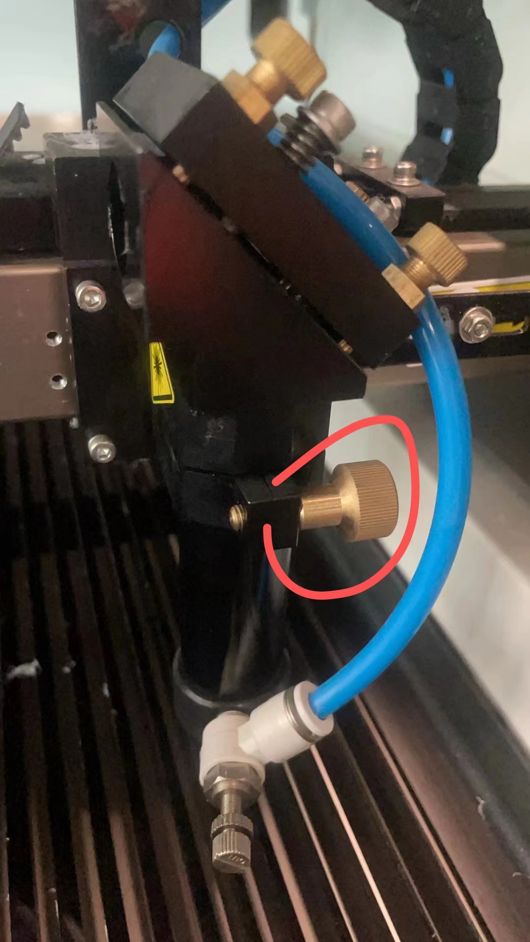
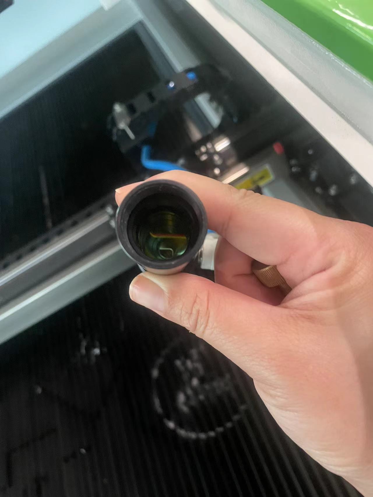
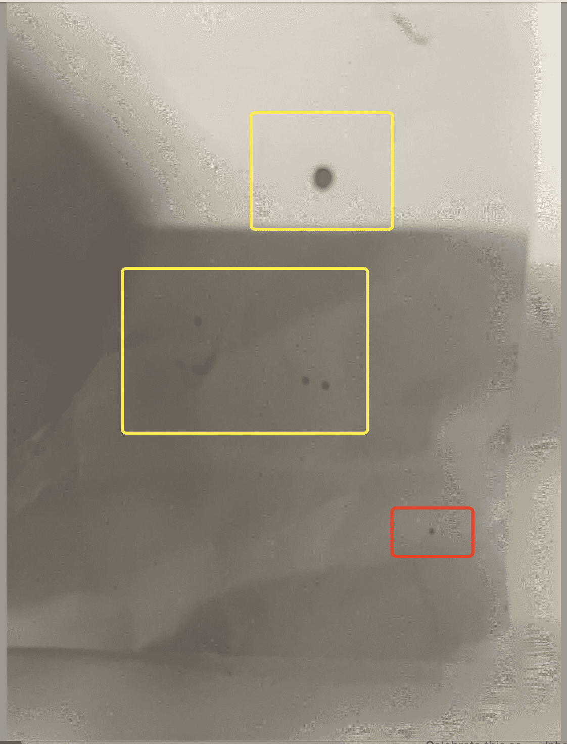
You can test it using a paper to find the best position of your focus lens, the smaller the dot, the better.
Step 2 Test the Kerf
First you need to make a kerf board like below :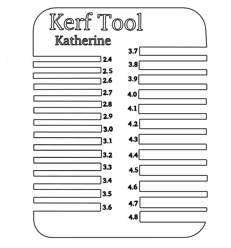
 |
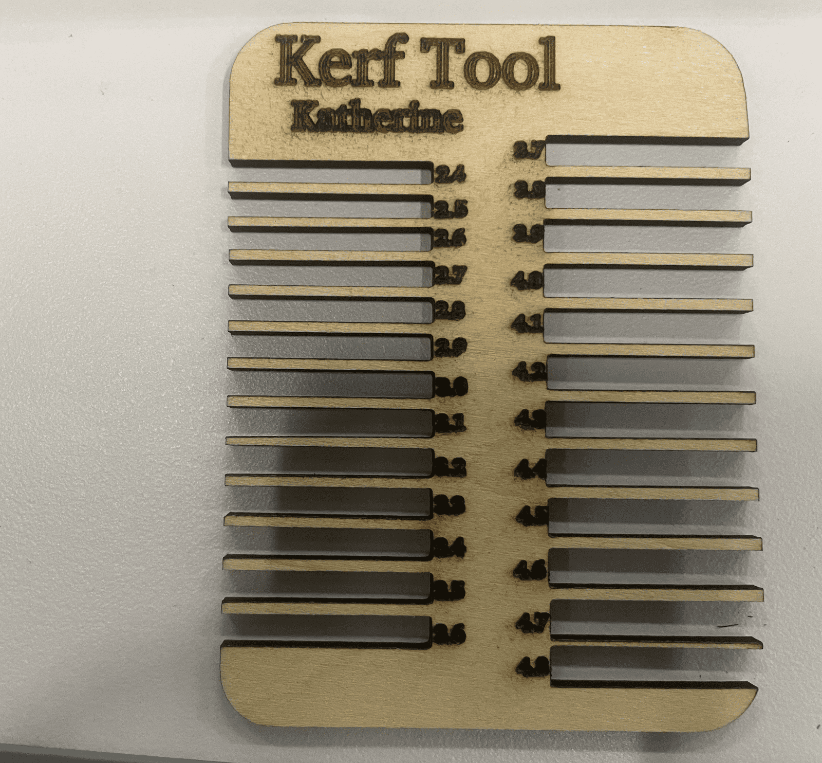 |
Set up the right power and speed for the wood board with thickness of 3mm(20% and 10) and cut the kerf tool first
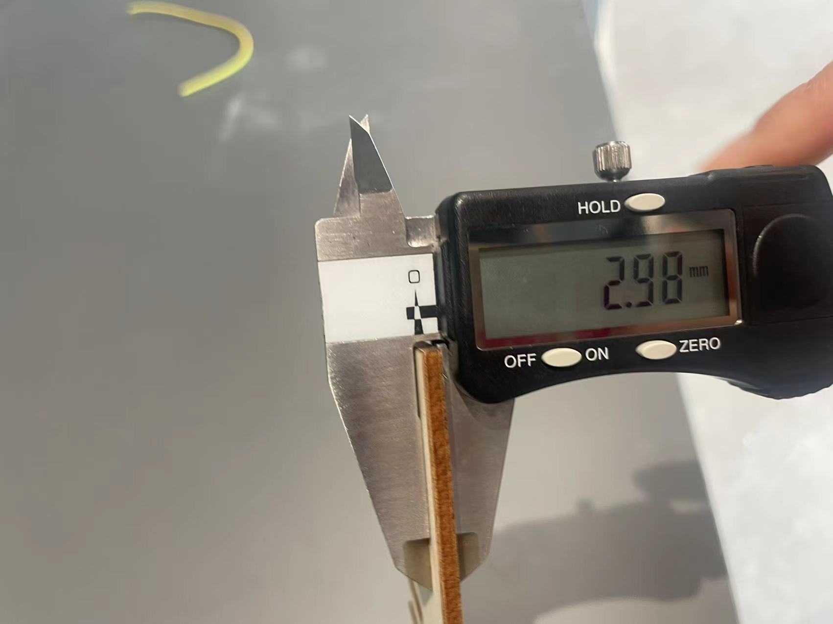
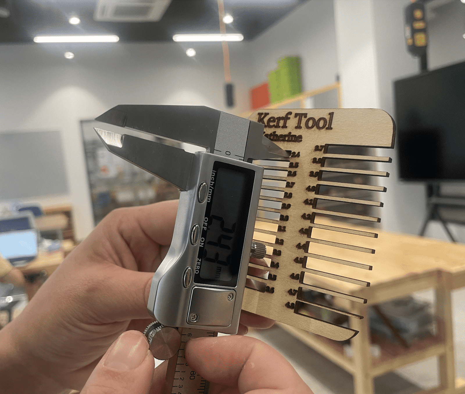
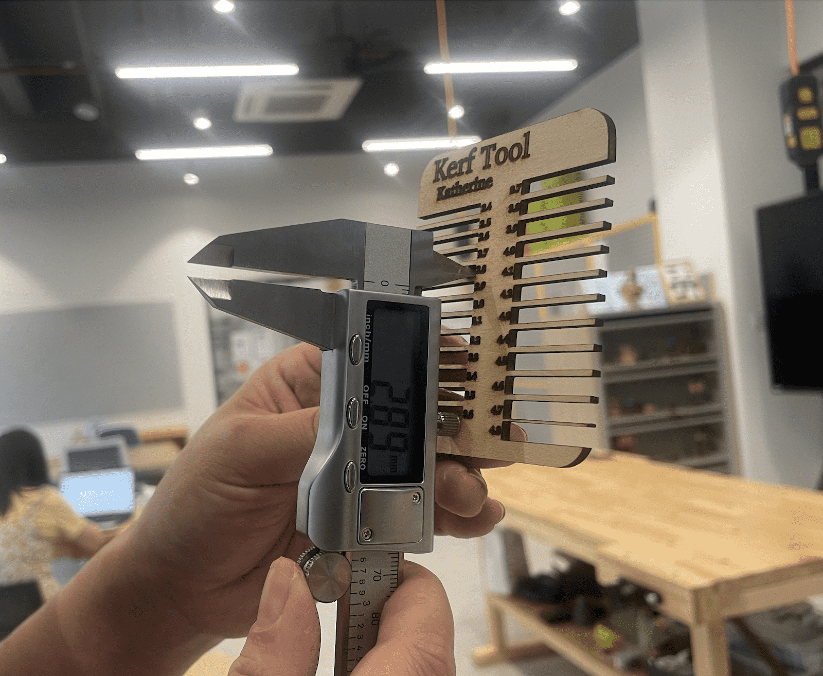
Later, when I tested the kerf value for 4mm and more, I found my gap was too thin and it will
be pushed by the vernier caliper, resulting in inaccurate data
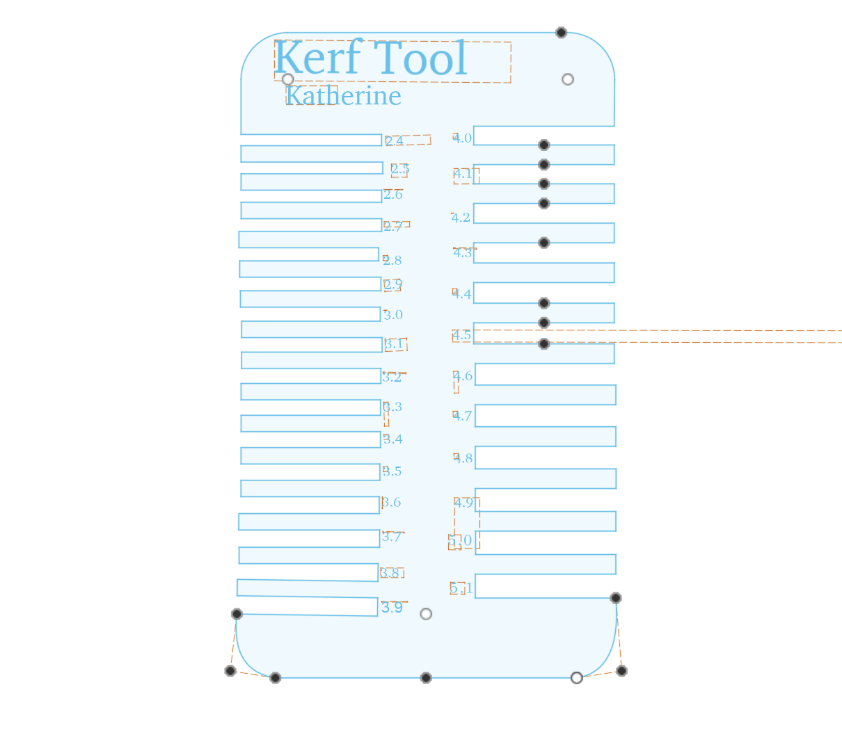
Then I made a new kerf board with better gap. And the dxf file can be downloaded in the resource file at the bottom.
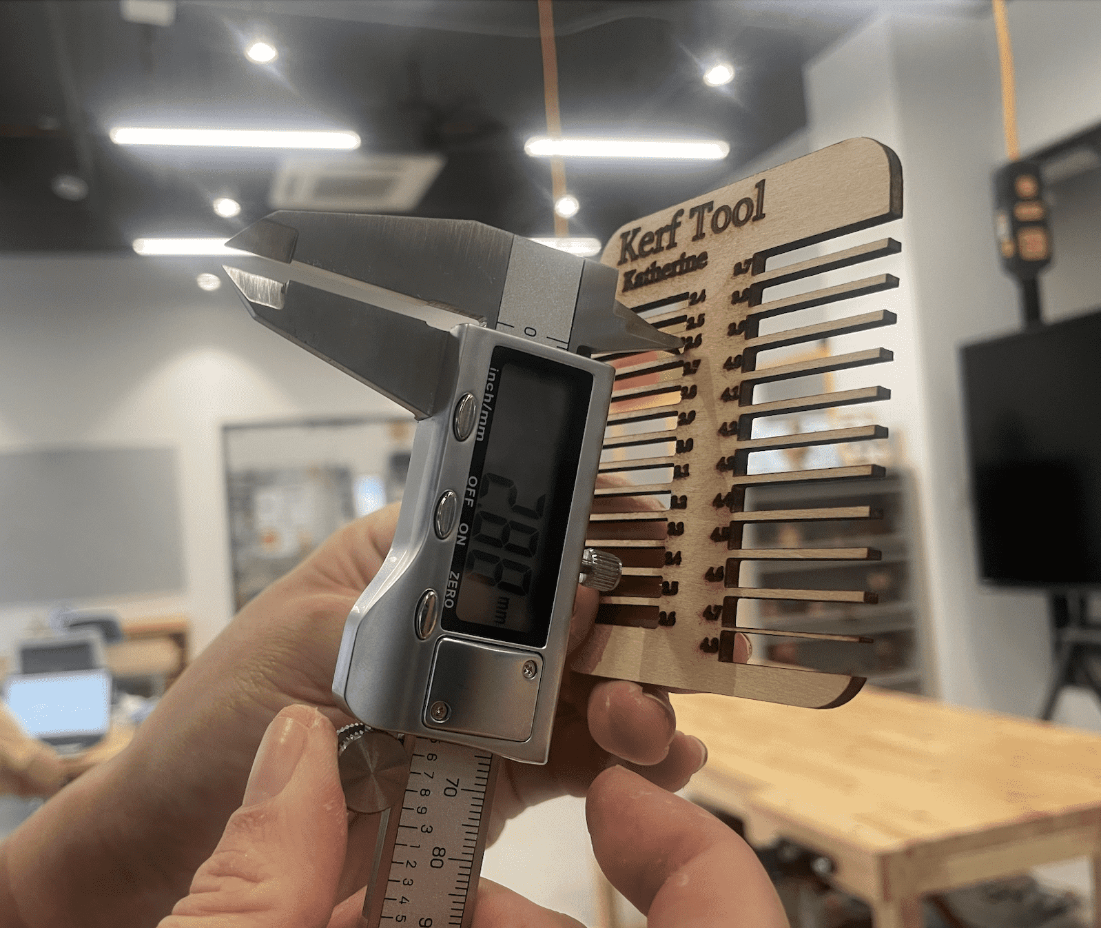
Step3 Test all the Kerf values
First, I designed the kerf tool, which can be downloaded in the resouces folder at the bottom. The destailed explaination about how the kerf tool made is in individual assigment part.
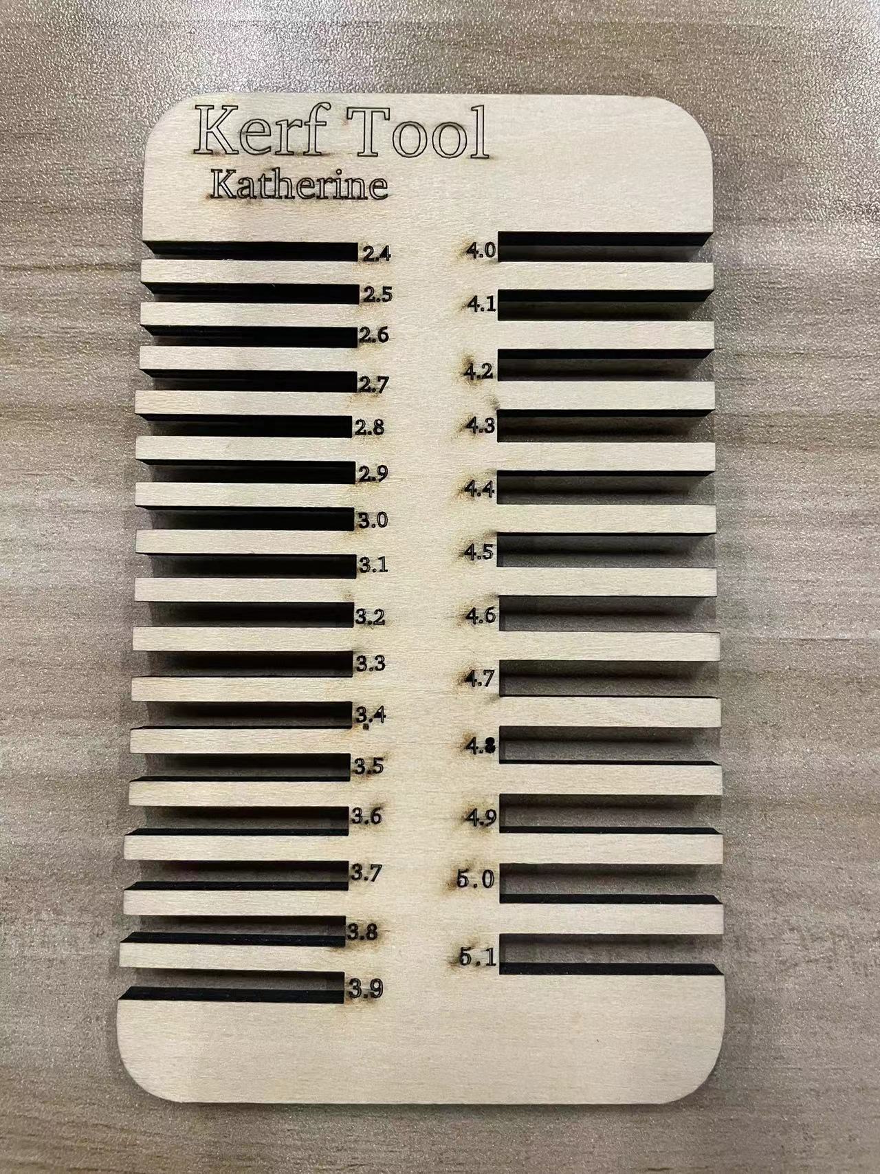
Then I cut it on all the different materials with different thickness.
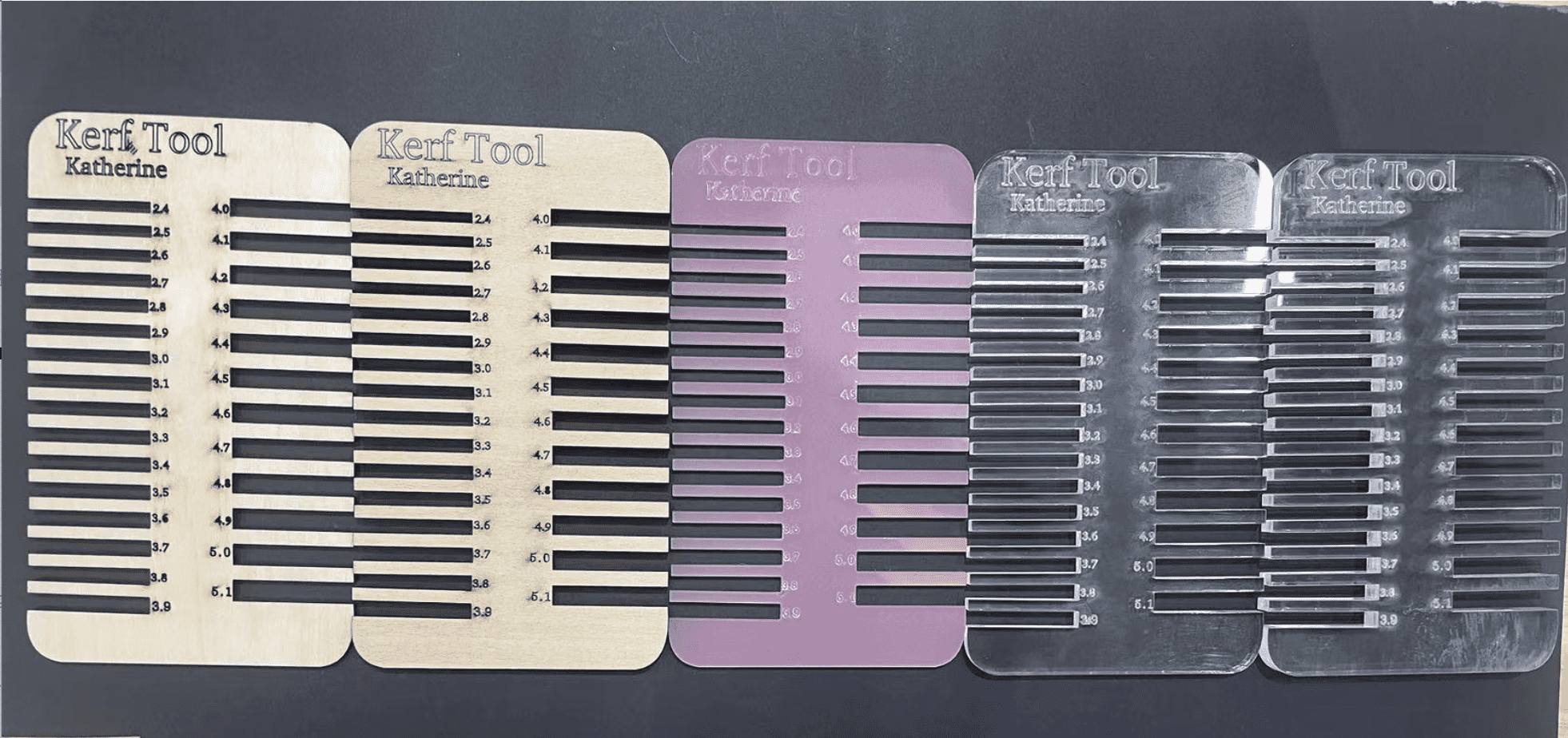
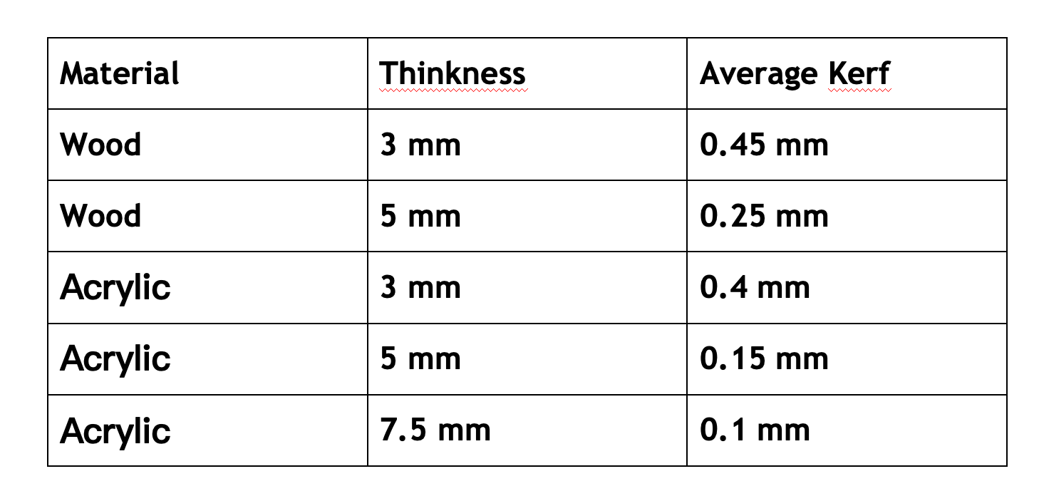
Measured all the kerf ranges.
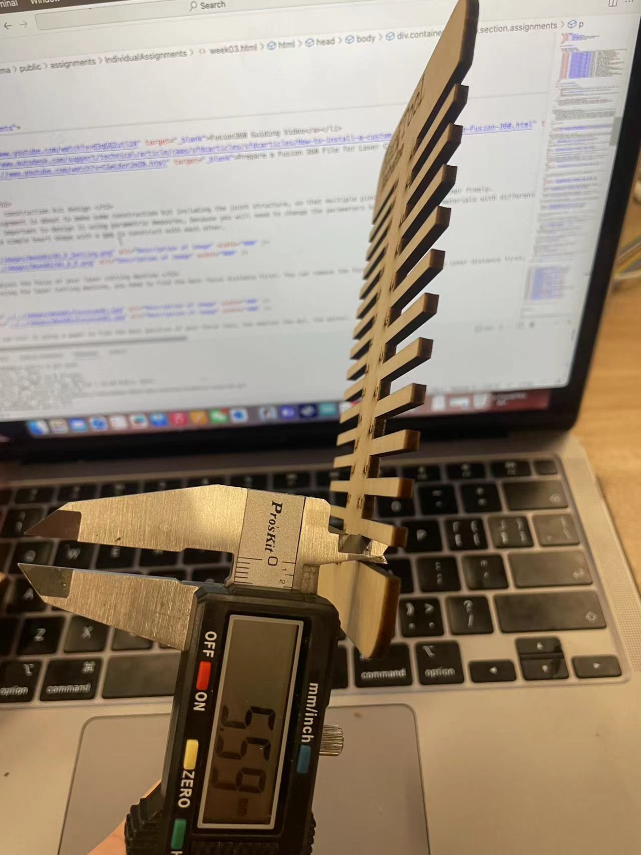

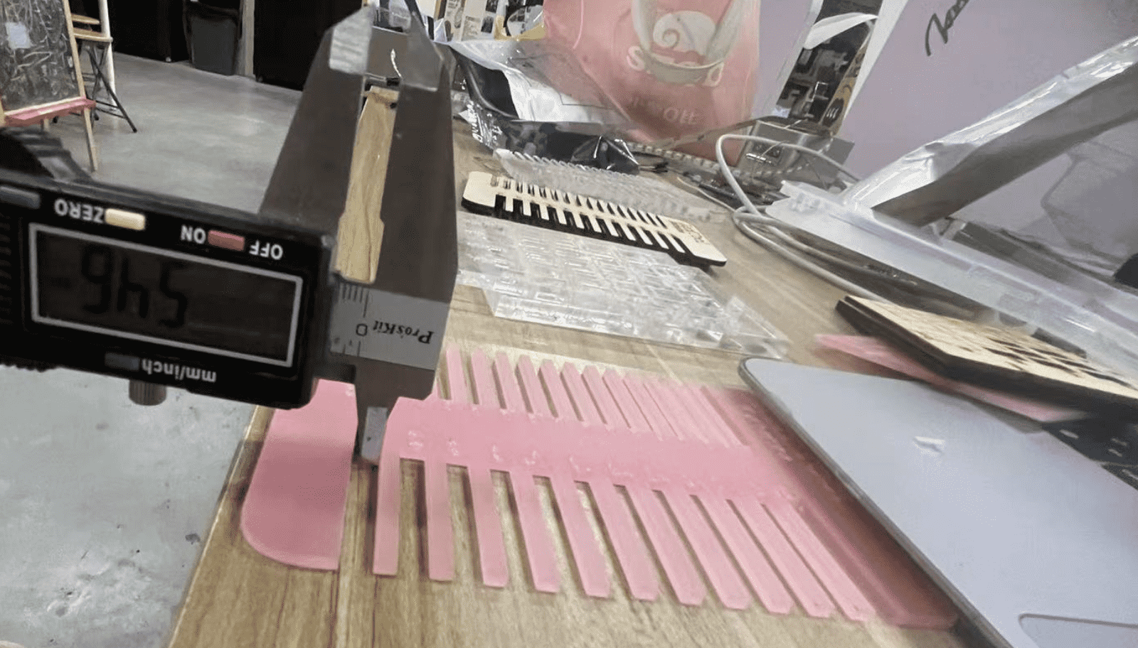
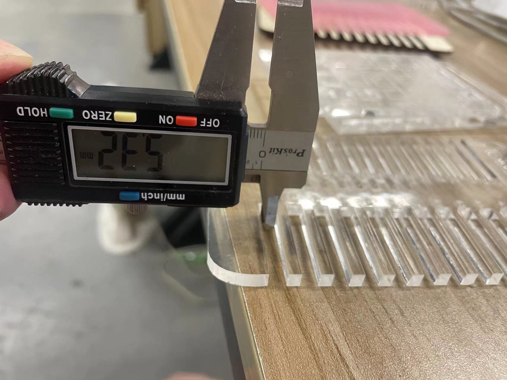
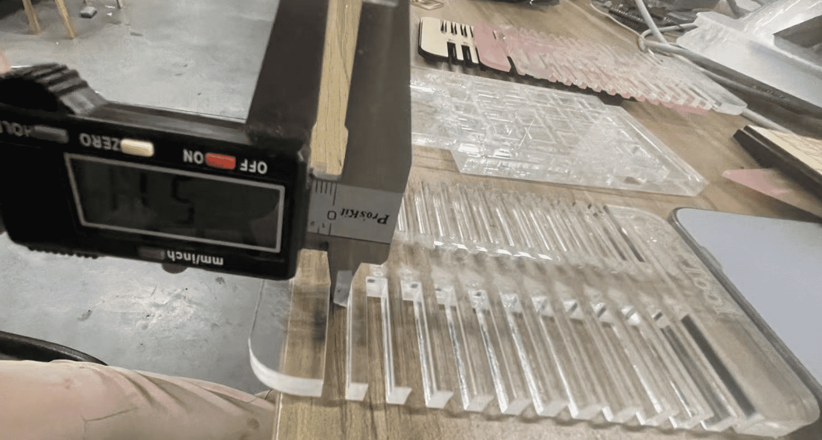
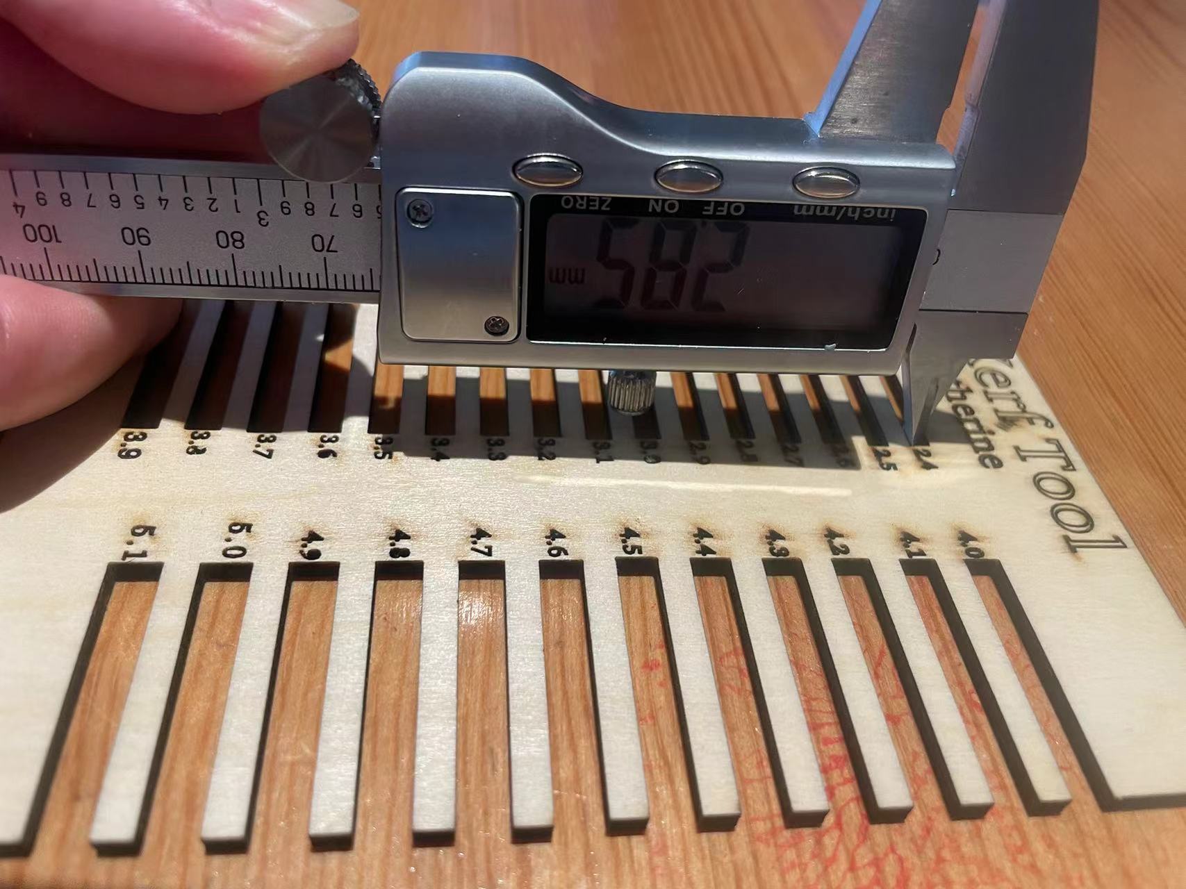
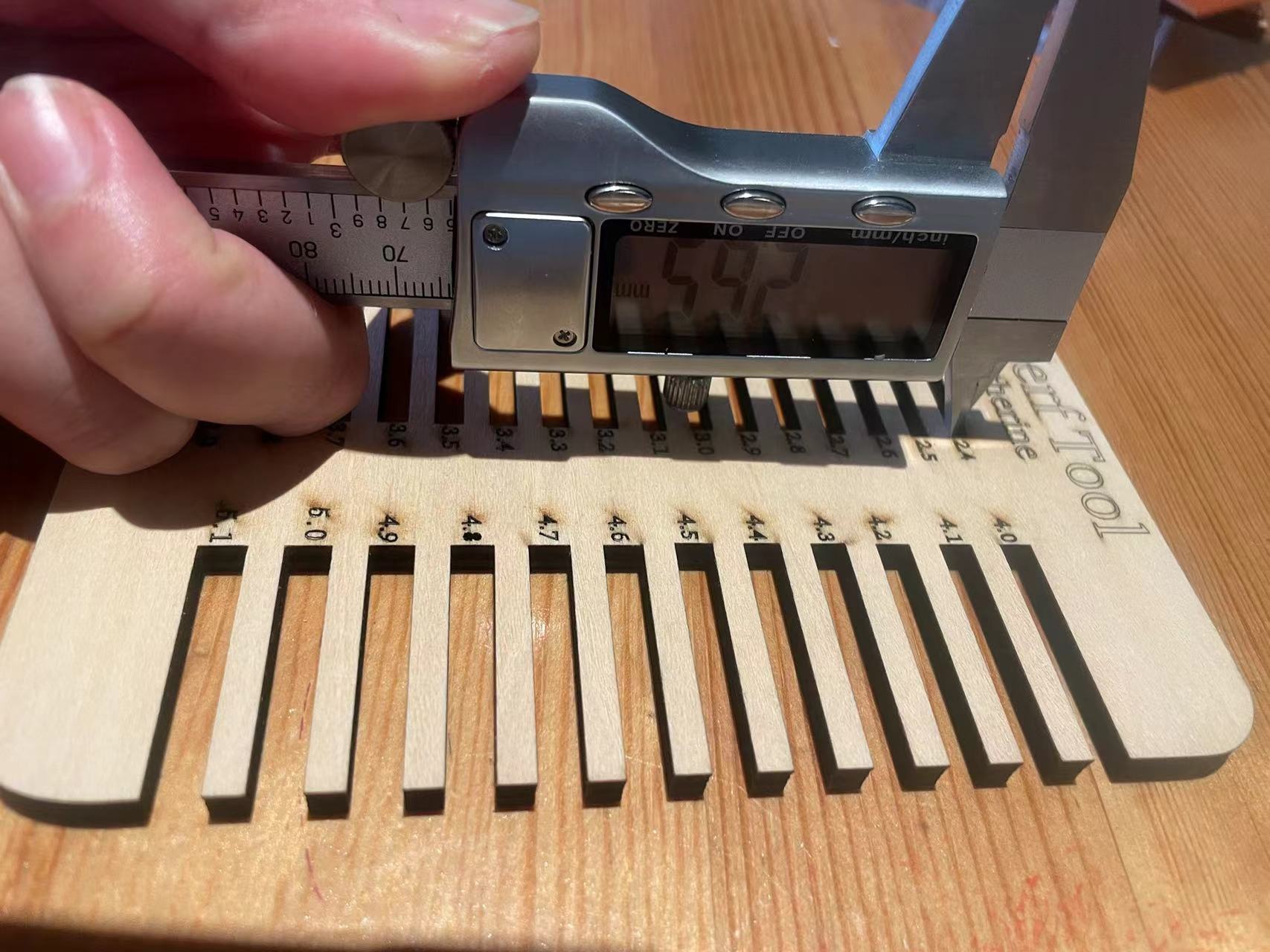

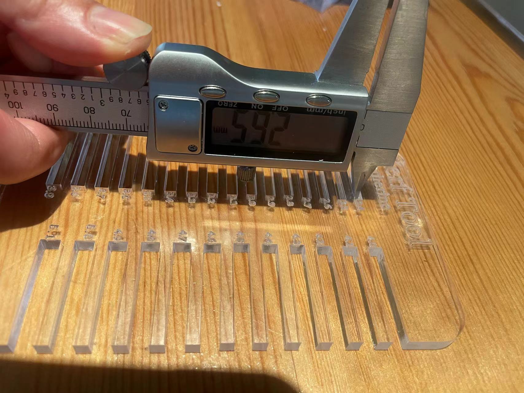
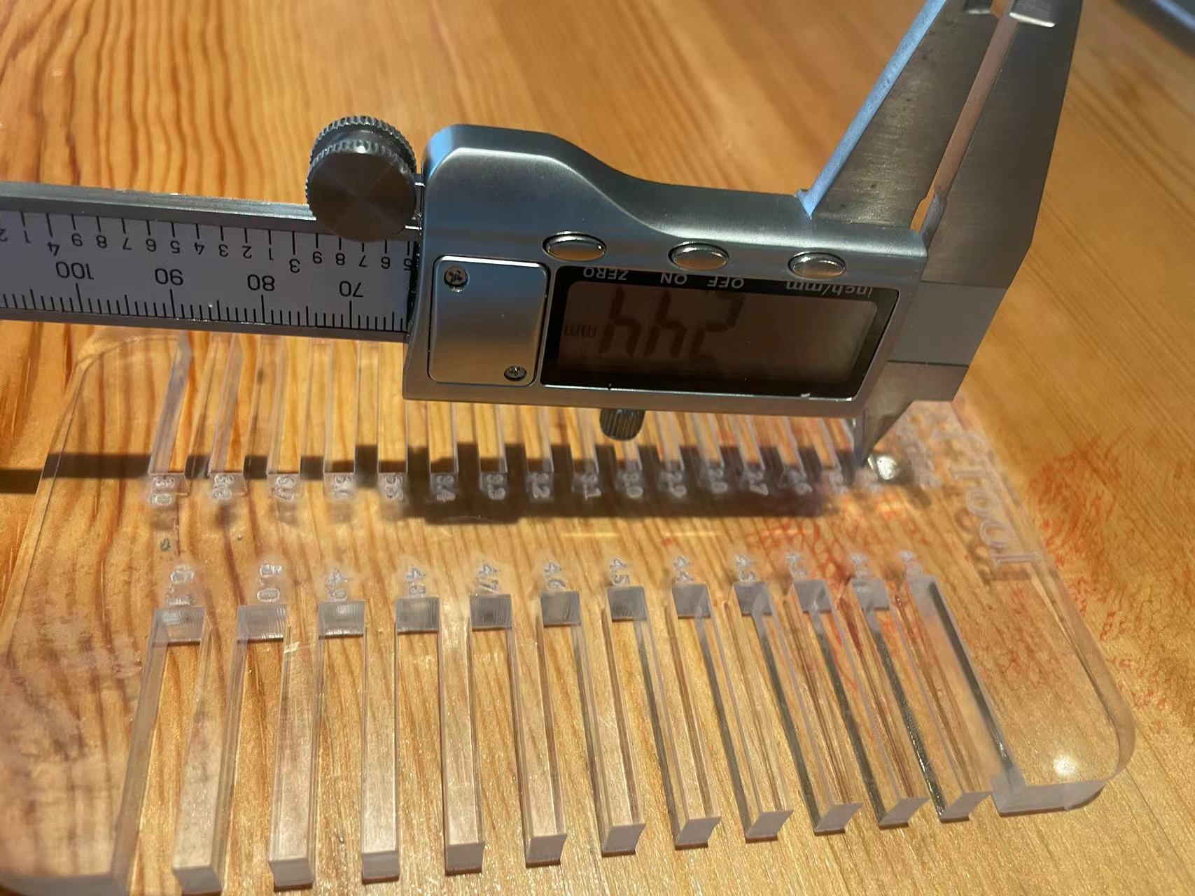
Sum up all the kerf values.
Part2. Test the cutting power and speed
Firstly, the power and speed were designed for this small square. Then, different speeds and power values were set for these squares respectively through different layers.
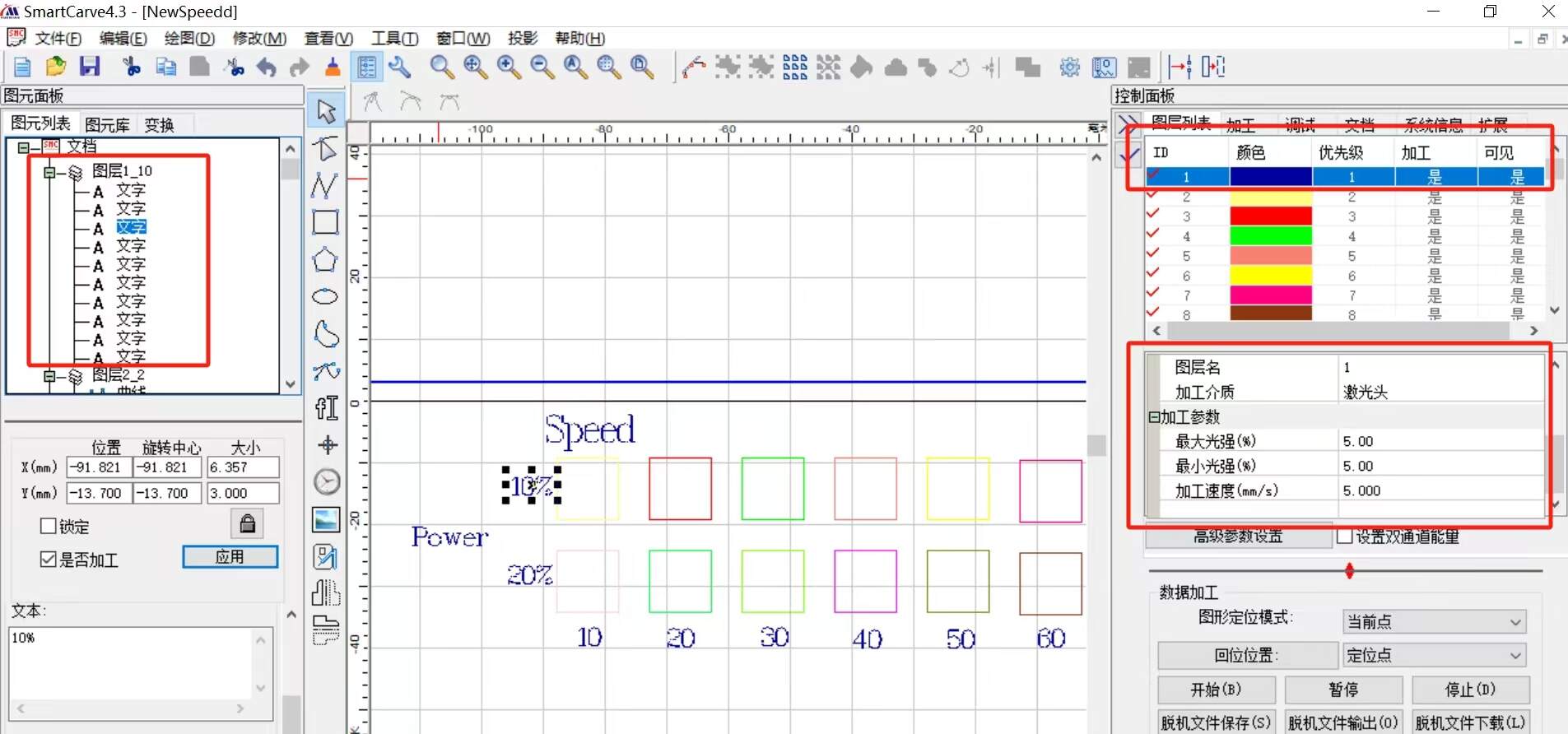
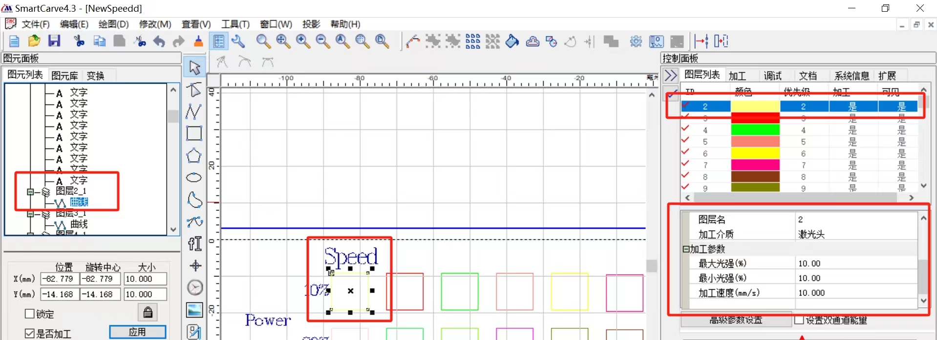
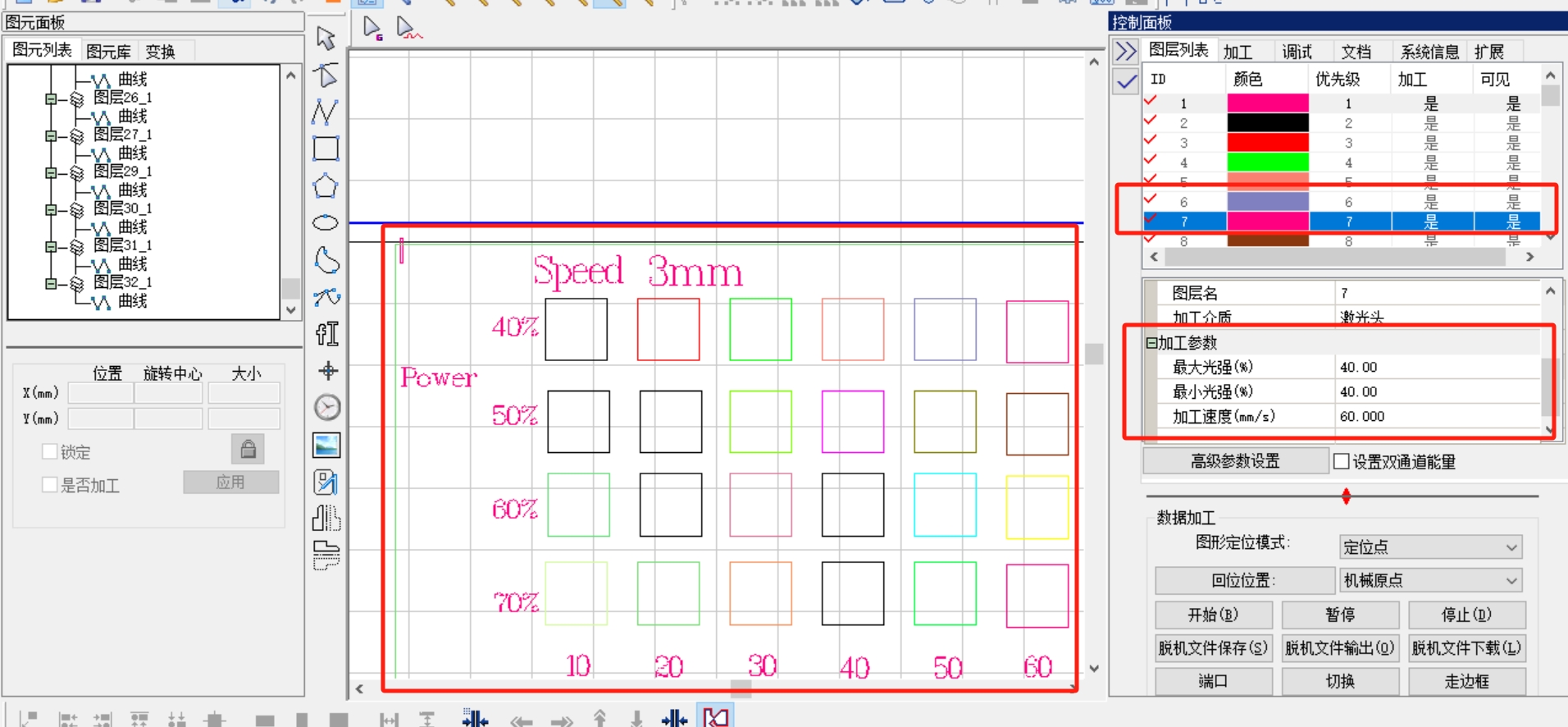
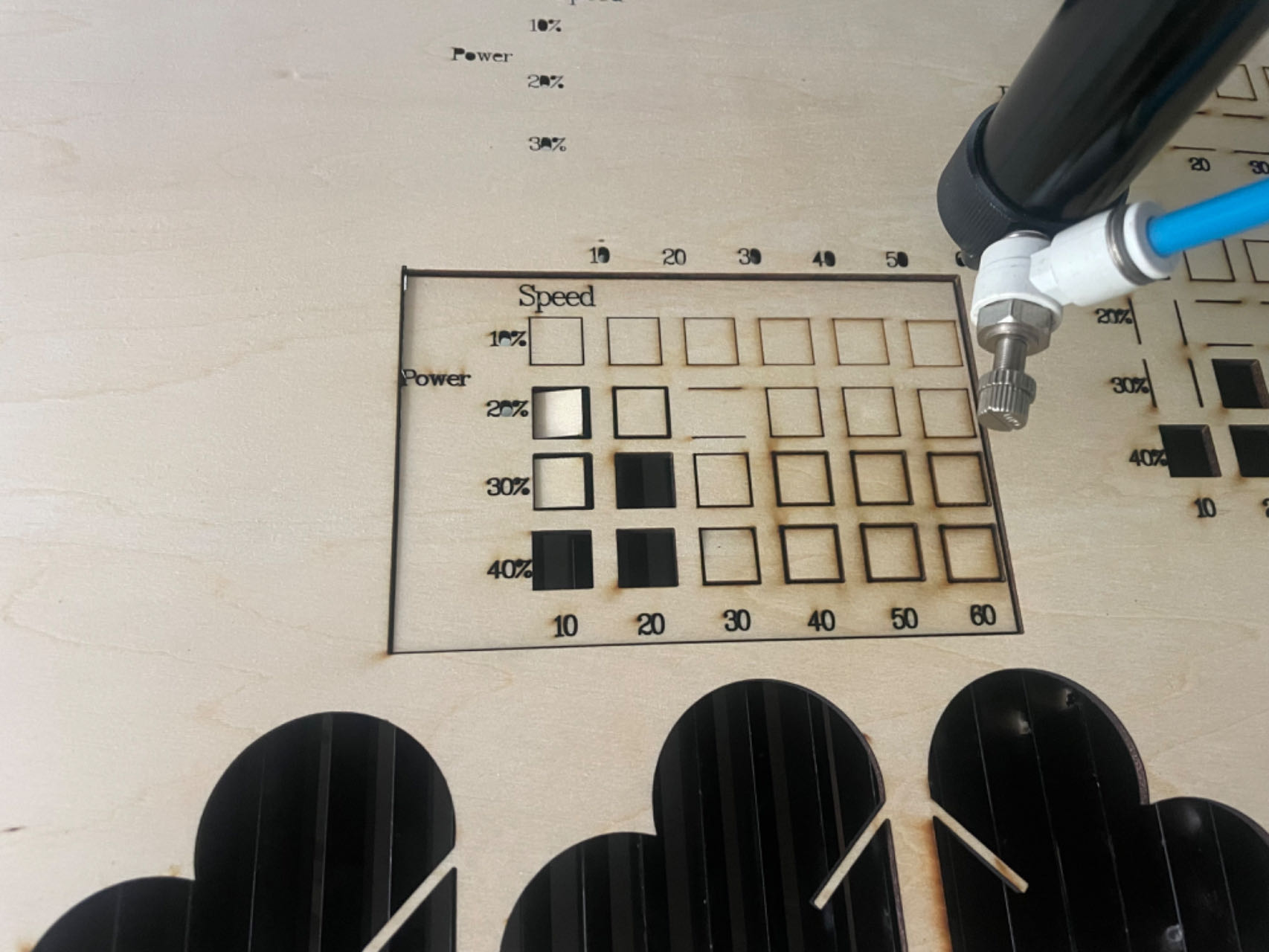
Image of all power and speed tested
- For the wood of 3mm and 5mm, acrylic of 3mm, the power range is from 10% to 40%, speed from 10 to 60
- For the acrylyc of 5mm and 7.5mm, the power range is from 40% to 70%, speed from 10 to 60
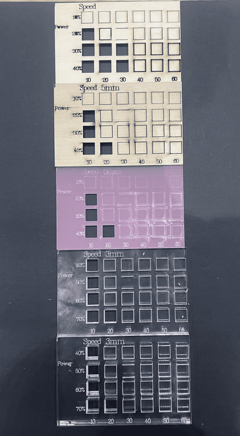
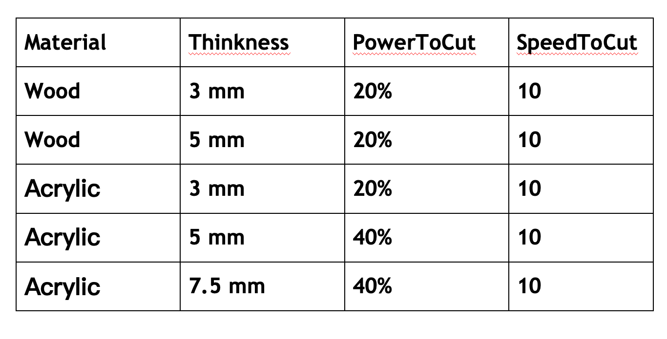
Finally, the summary of the power and speed that can completely cut through various materials is as follows:
In addition, this test data can also be used as a reference for the later production of relief effects.It can be seen that the faster the speed, the thinner the relief lines.
Individual Assignments
Step 1 Make your construction kit design
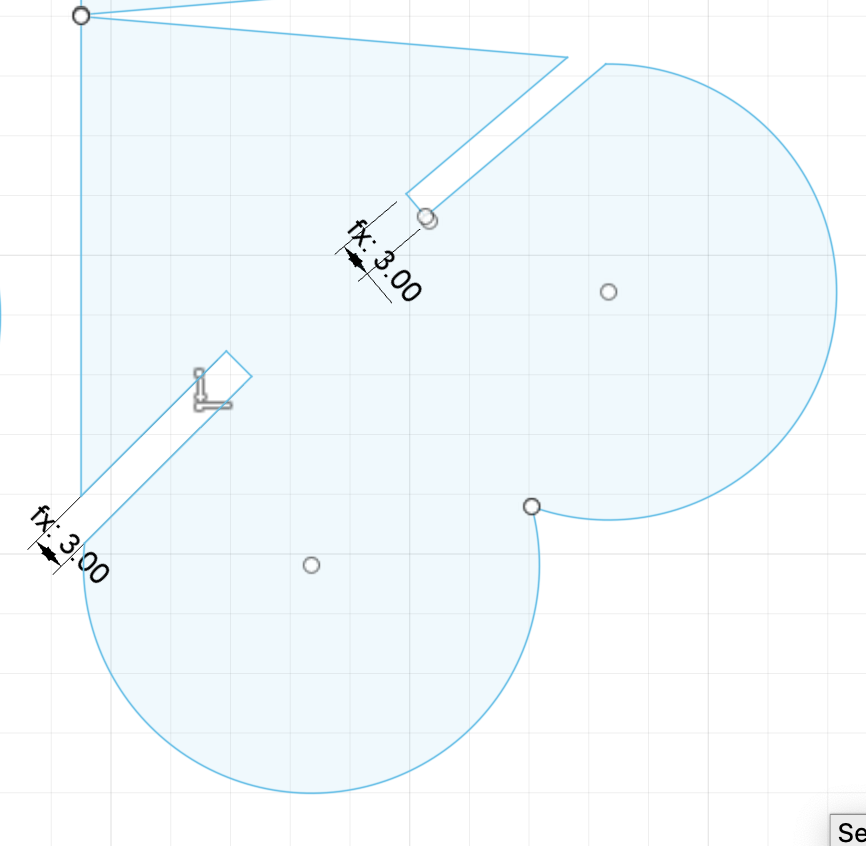
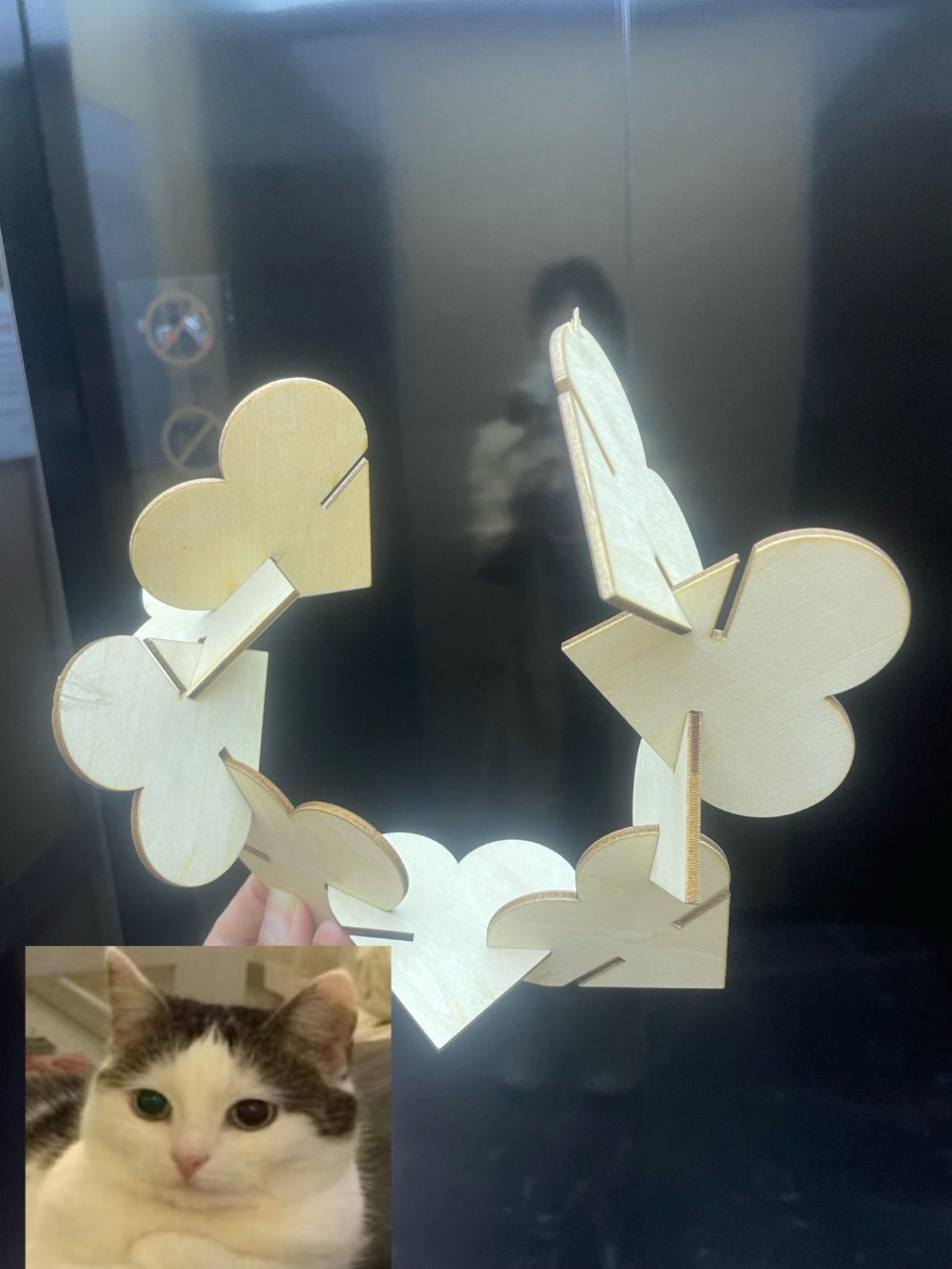
This week's assignment is about to make some construction kit including the joint structure, so that multiple pieces can join each other freely. And it is very important to design it using parametric measures, because you will need to change the parameters based on different materials with different thicknesses and kerf values. My design is a simple heart shape with a gap to construct with each other。
Step 2 Test the Kerf and Modify parameter in Sketch
 |
 |
 |
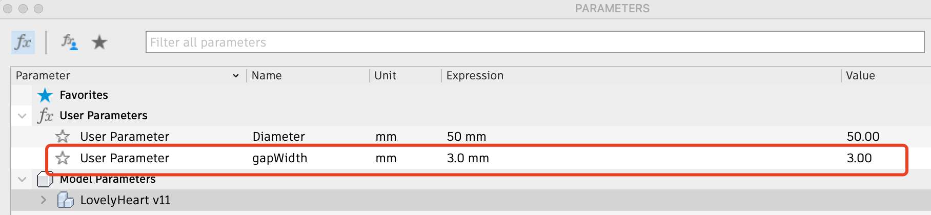
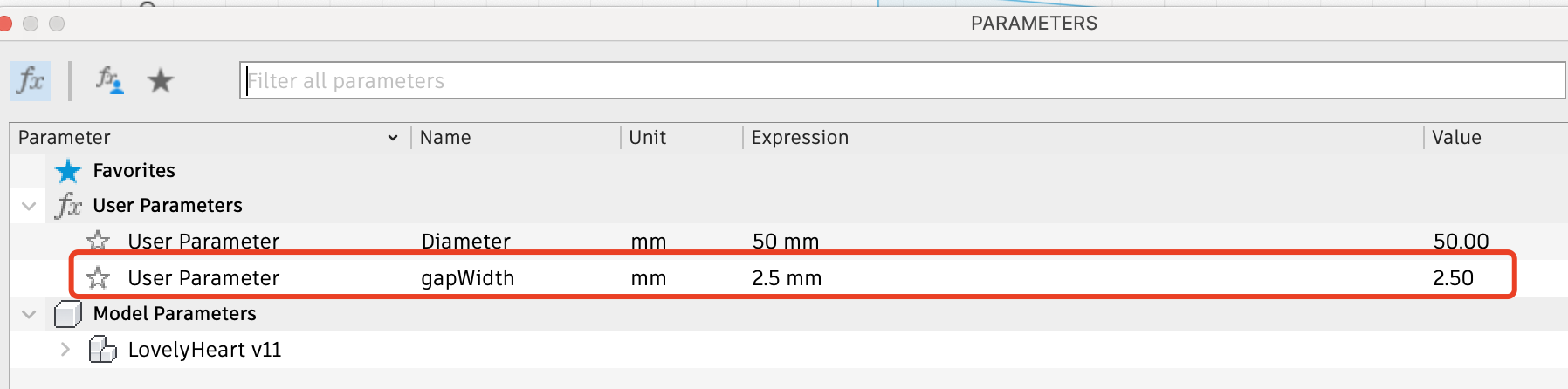
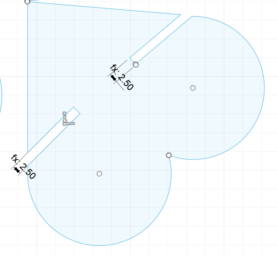
Based on my kerf tool, to get the 3mm gap, the parameter of the board should be set as 2.5mm.
Then I changed the parameter value of the gapWidth to be 2.5mm, and the heart shape will automatically change
Later, when I tested the kerf value for 4mm and more, I found my gap was too thin and it will
be pushed by the vernier caliper, resulting in inaccurate data
Then I made a new kerf board with better gap. And it can be downloaded in the resource file at the bottom.
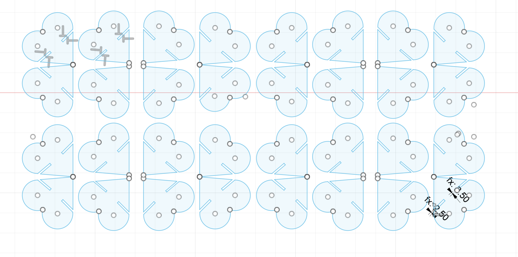
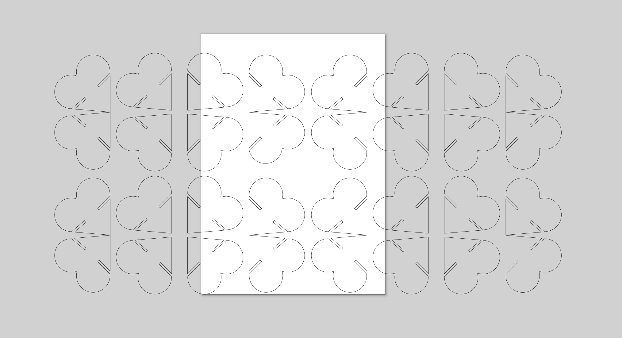
Step 3 Copy And Paste to make multiple hearts
Once the parameter for the single heart is completed, you can proceed to copy and paste to create multiple hearts for cutting. It is better to make the gaps between the hearts to be as smaller as possible to save the material use as well.
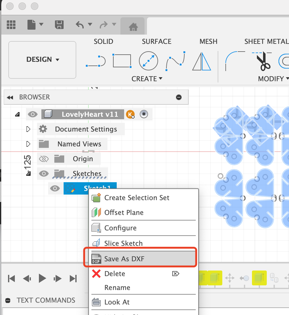
On sketch, right click to saveAsDxf file
Use inkSpace to check the dxf file whether the dxf file has all the curve
Step 4 Prepare the Laser Cutter Machine to cut!
There are still many sub-steps about how to use a laser cutter machine to cut, please be patient and follow
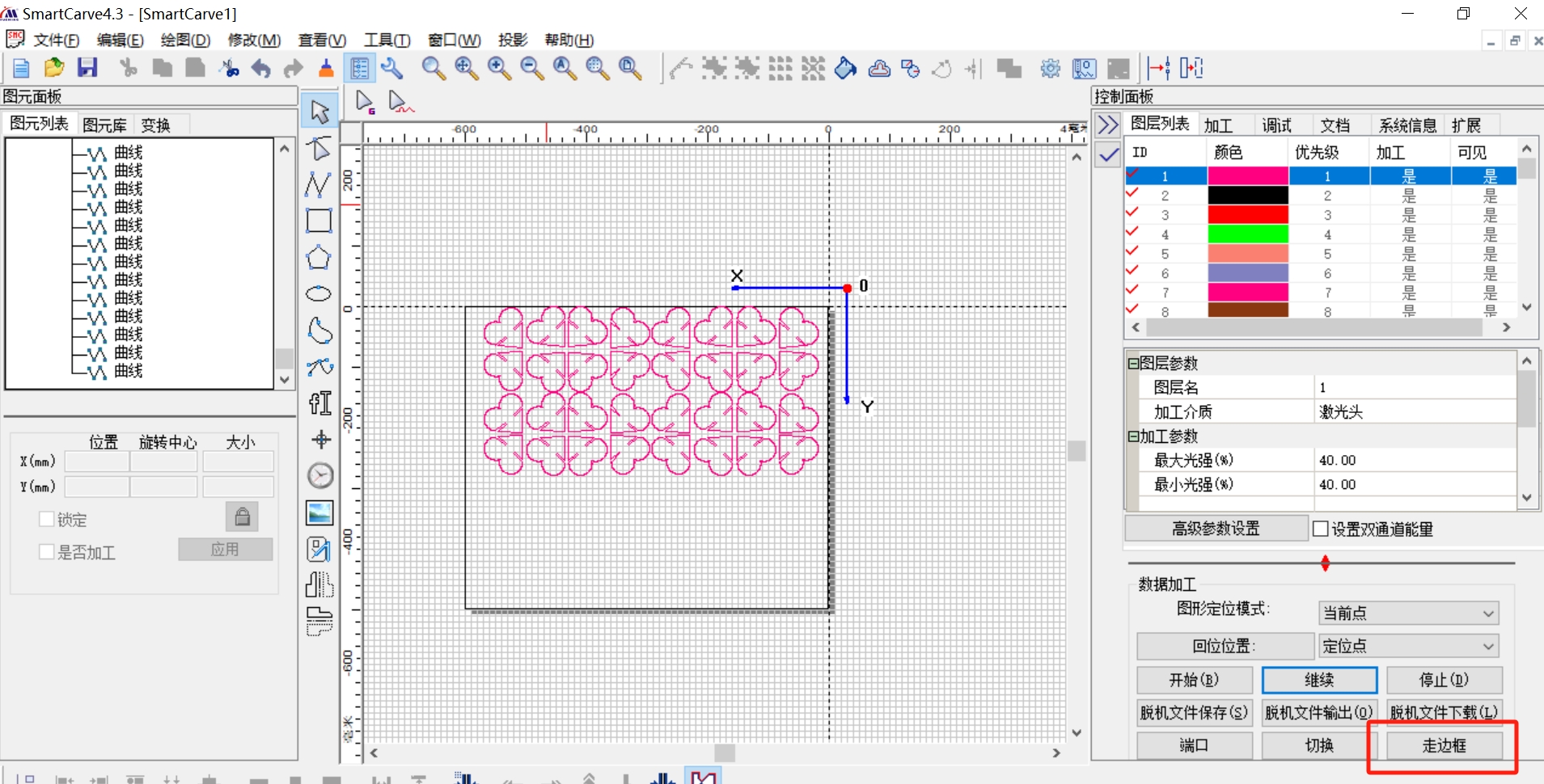
Load the design file:
1. Upload the digital design file containing the cut path into the laser cutter's software.
Ensure the file is properly scaled and oriented on the virtual cutting bed.
2. Perform a frame walking to Trace the border of the design to ensure the cut lines are positioned correctly.
Check that the cut lines are not overlapping or intersecting in unintended ways.
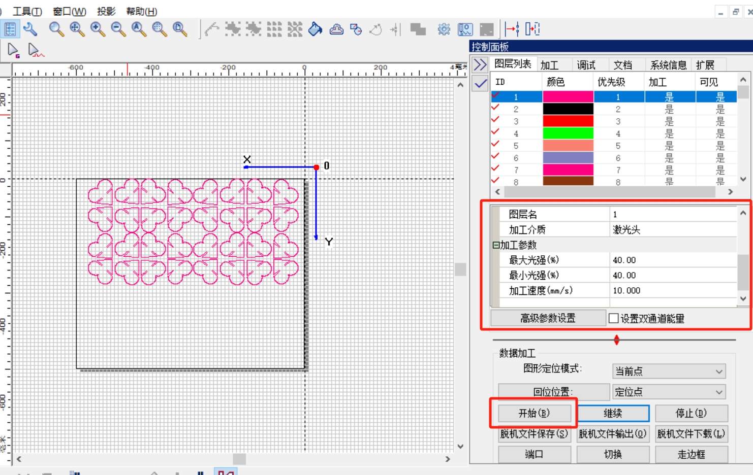
3. Based on the preview, fine-tune the laser power, speed, and focus settings.
Optimize the parameters for clean, precise cuts along the border of the 3mm board.
Ensure the kerf width is appropriate for the material thickness.
Adjust the cutting parameters:
4. Many laser cutters have a feature to simulate the cutting operation.
Run this simulation to visualize the actual cutting path and identify any potential issues.
Verify that the simulated cuts match the intended design.
5. Double-check that the 3mm board is securely positioned on the cutting bed.
Ensure there are no warps, bends, or other irregularities in the material.
Make any necessary adjustments to the material placement.
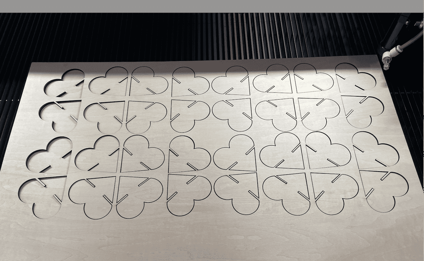
Initiate the cutting operation:
Only after thoroughly reviewing the design, settings, and material placement should you begin the actual laser cutting process. Monitor the cutting closely and make any real-time adjustments as needed.
Step 5 Assemble
Vinyl Cutter
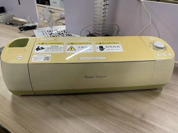
Step 1 Download the software that matches our machine
The machine in our lab and the software needed

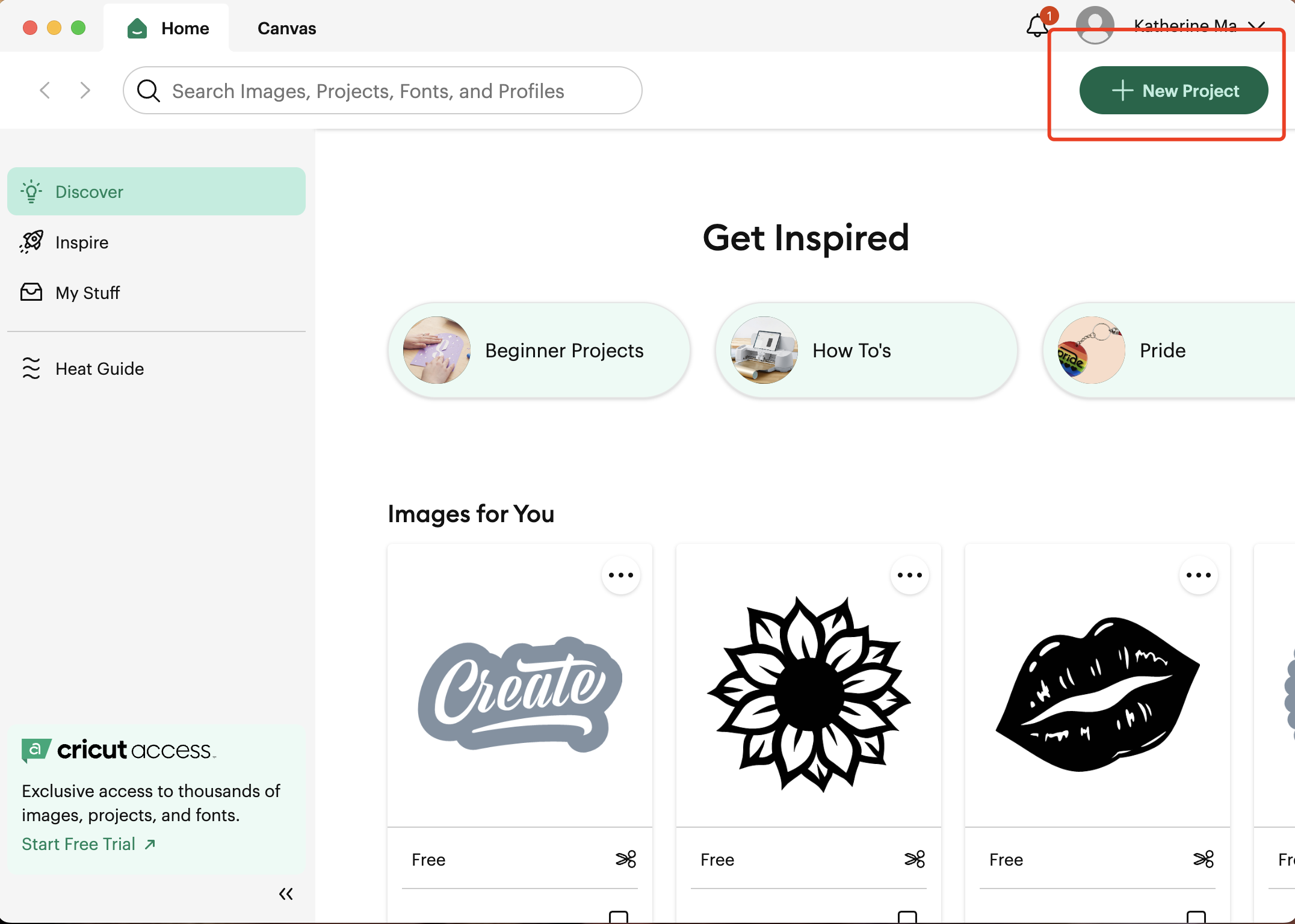
Step 2 New a project
Step 3 Upload the image to cut, and I used a svg file downloaded online

Step 4 View of uploaded image
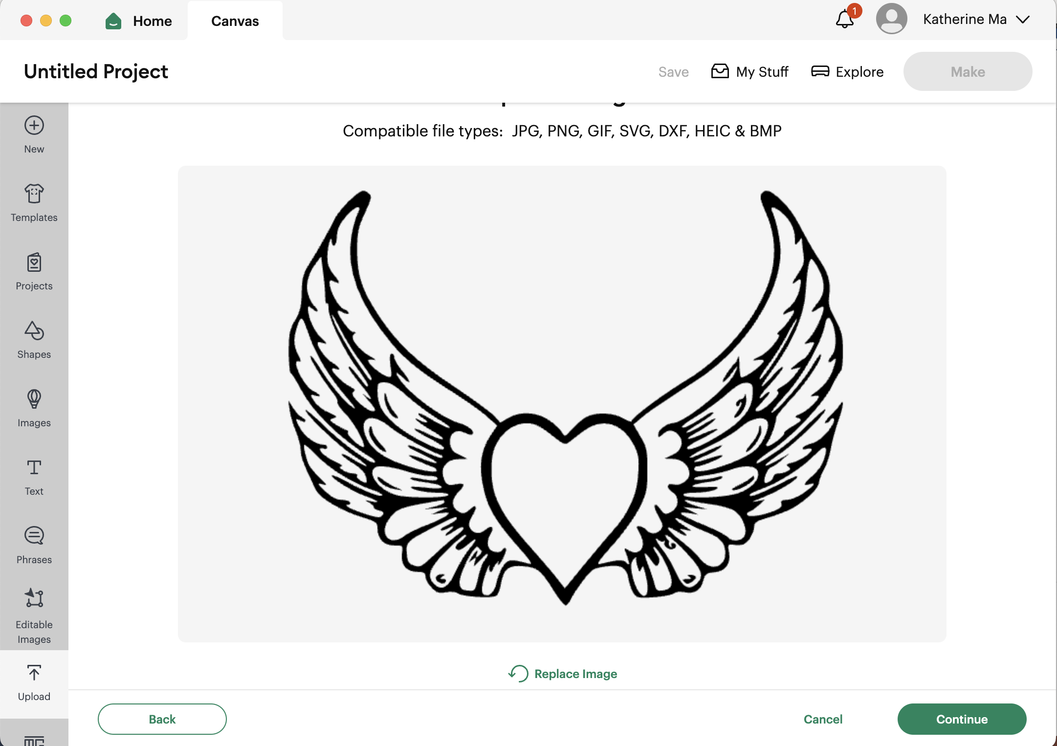
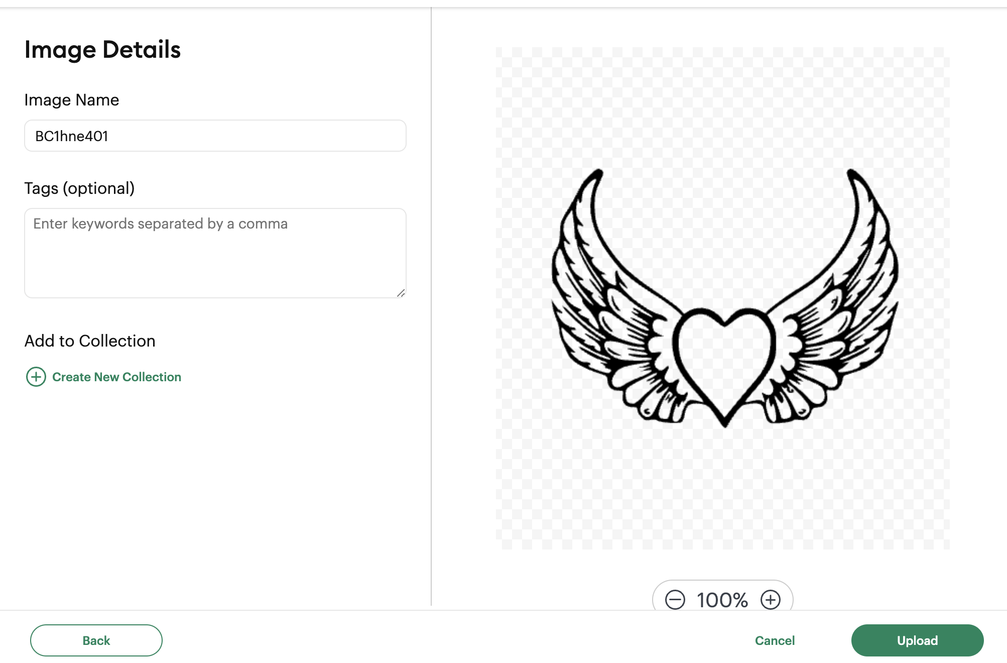
Step 5 Image details and press upload
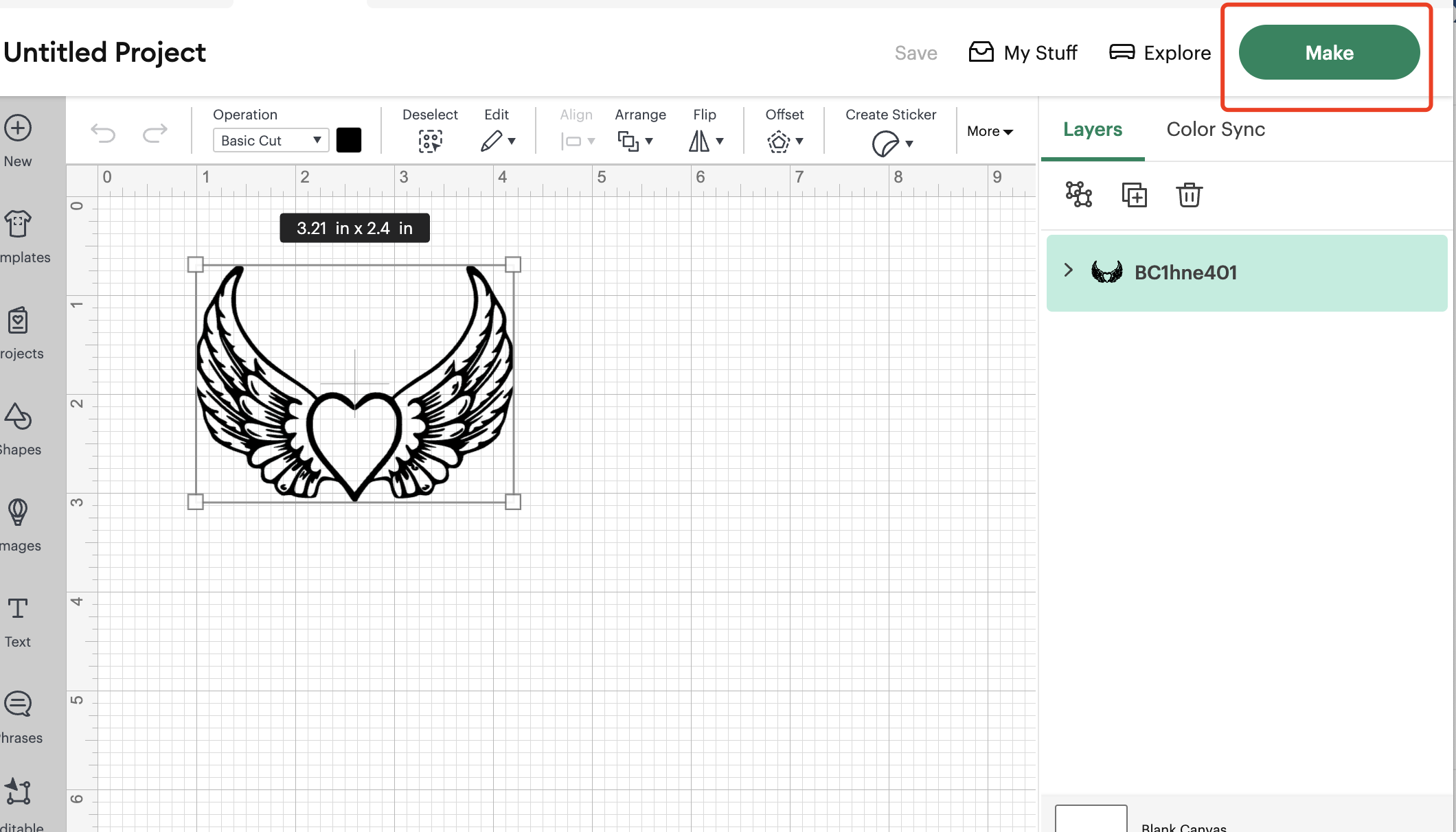
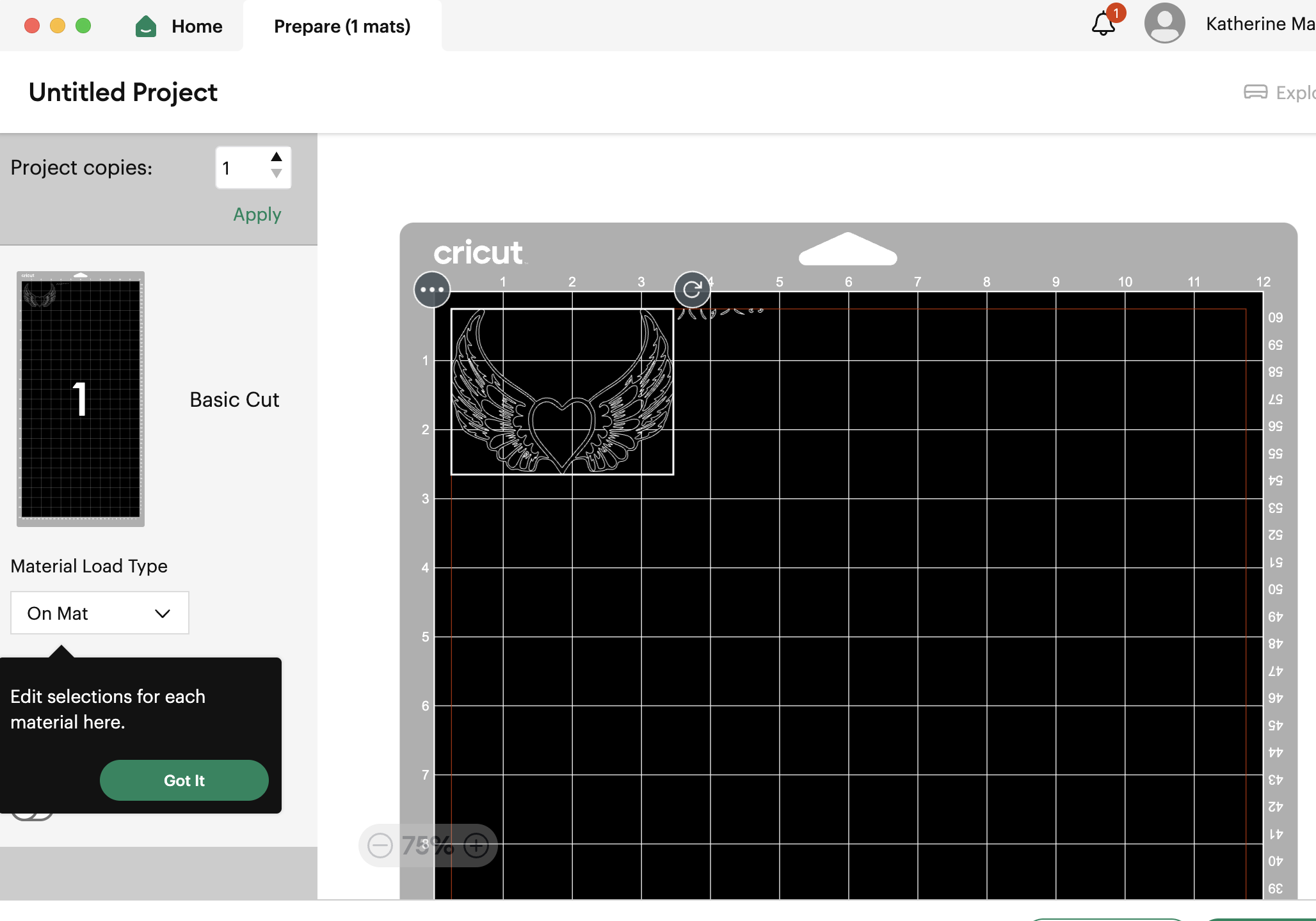
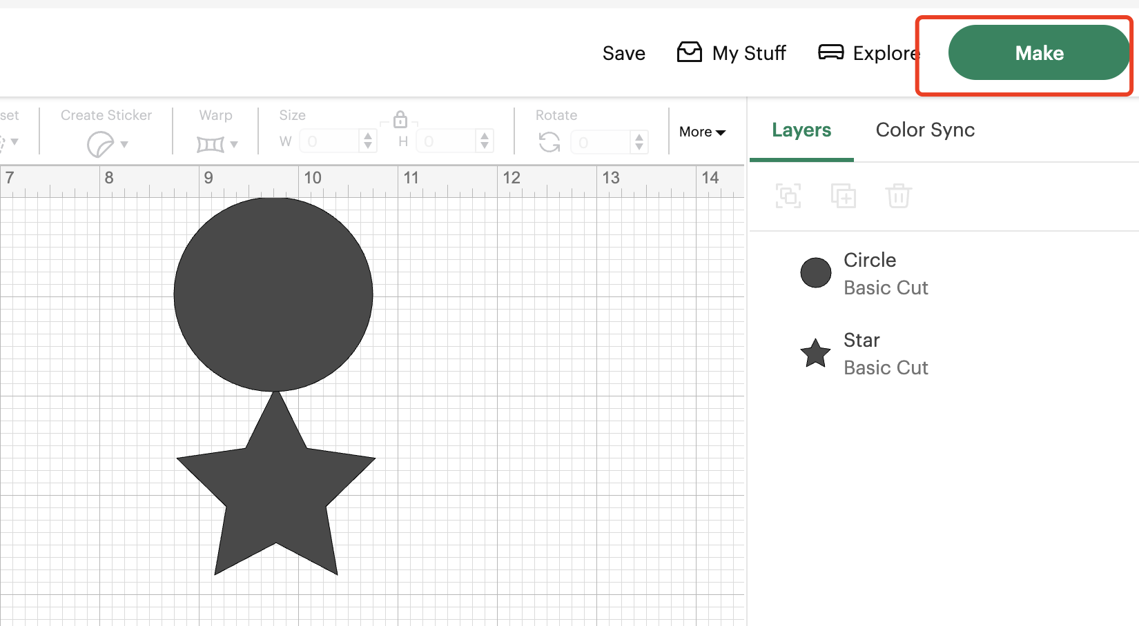
Step 6 Image with the gridded background and press ”Make“
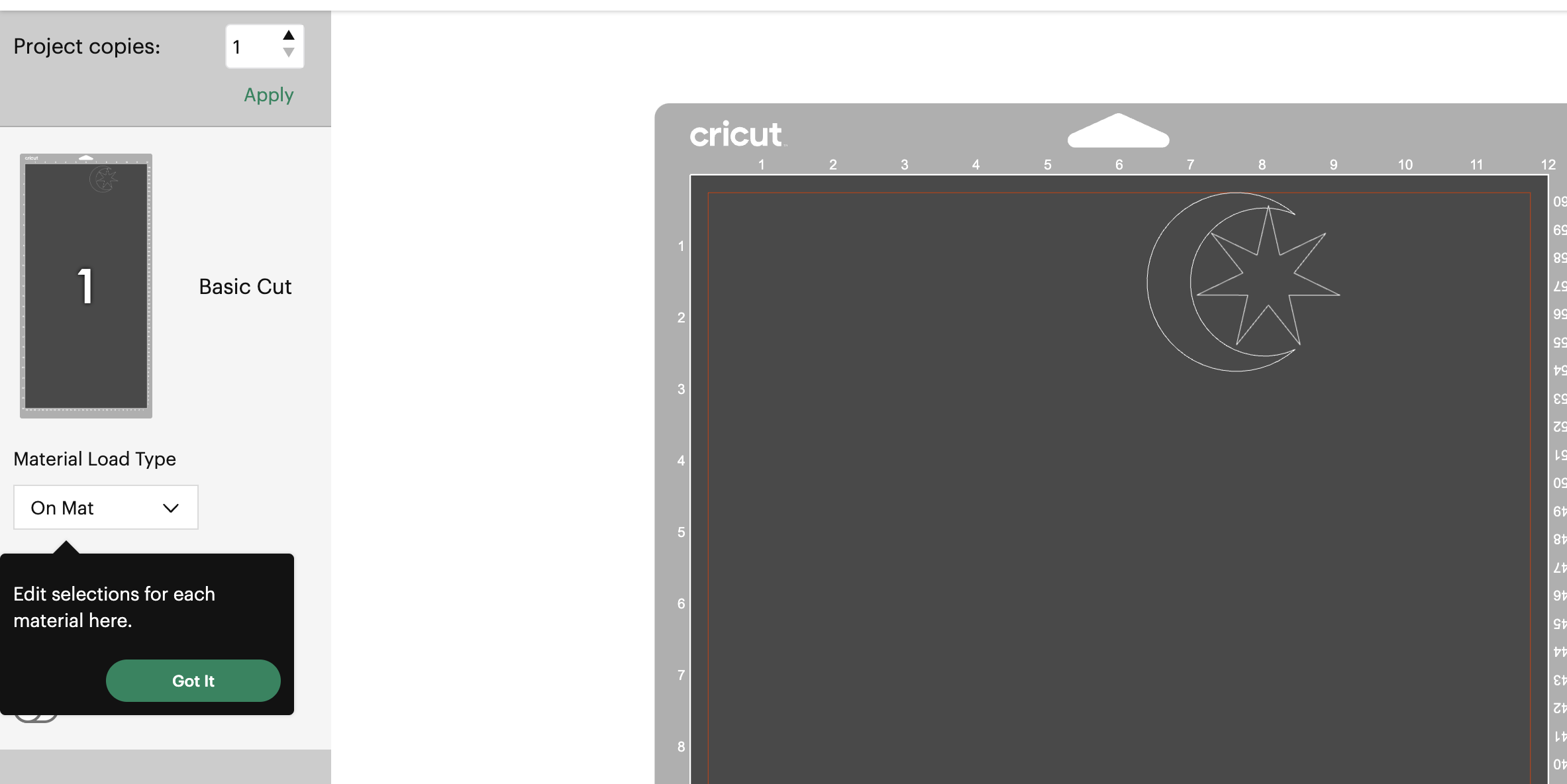
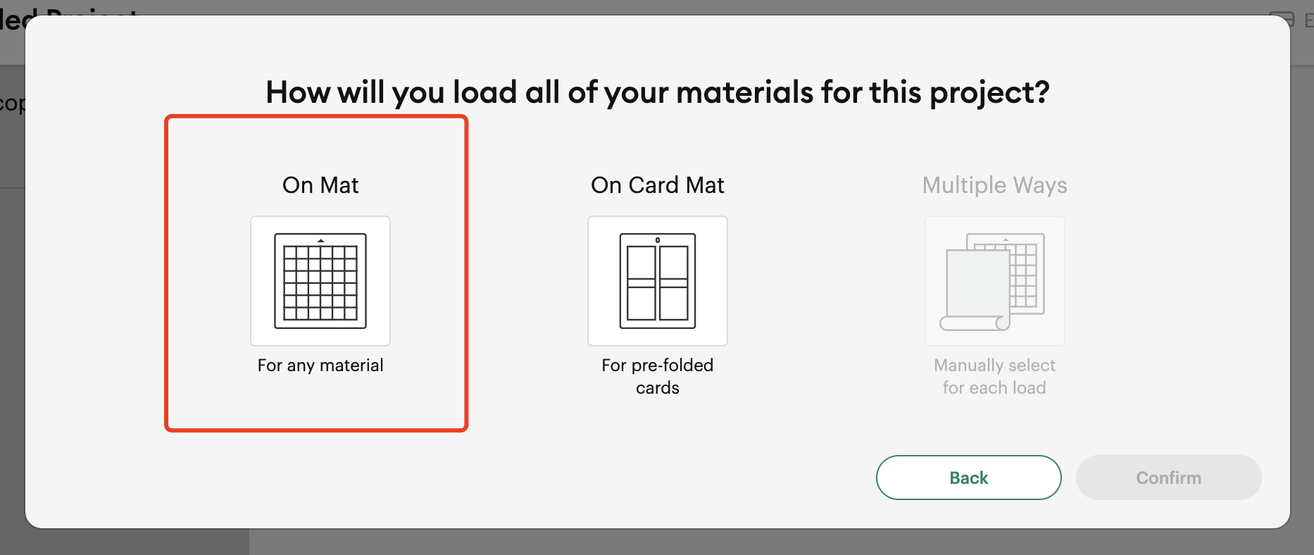
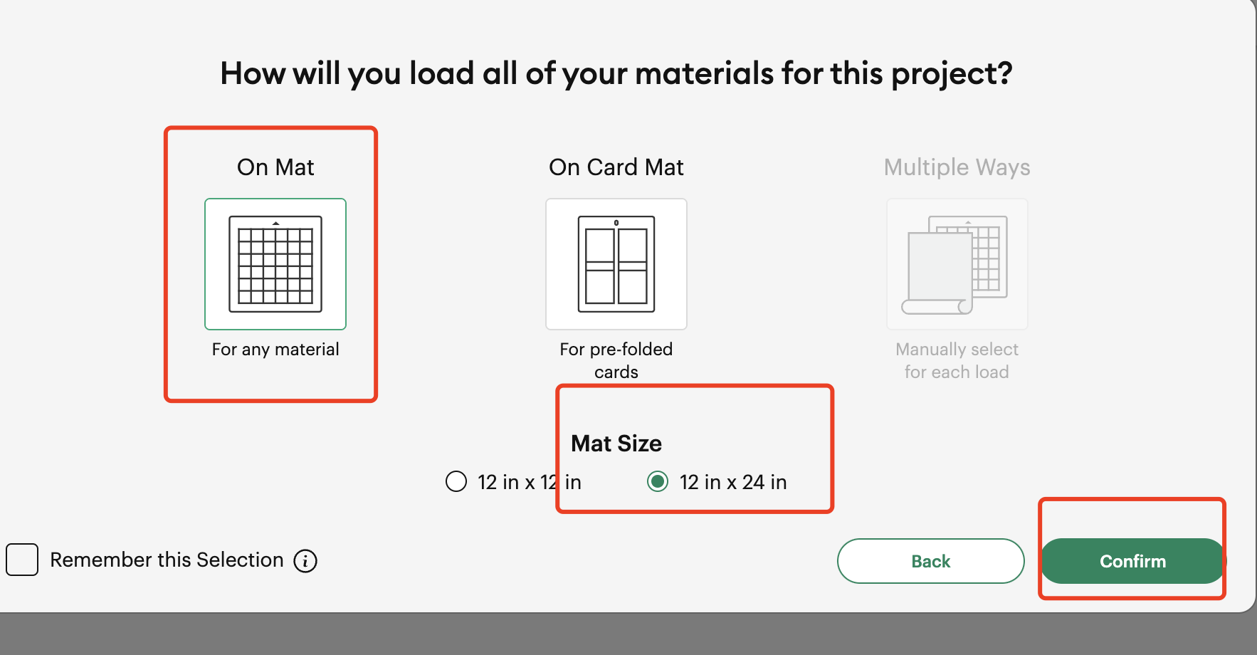
Step 7 Choose the Mat for cutting
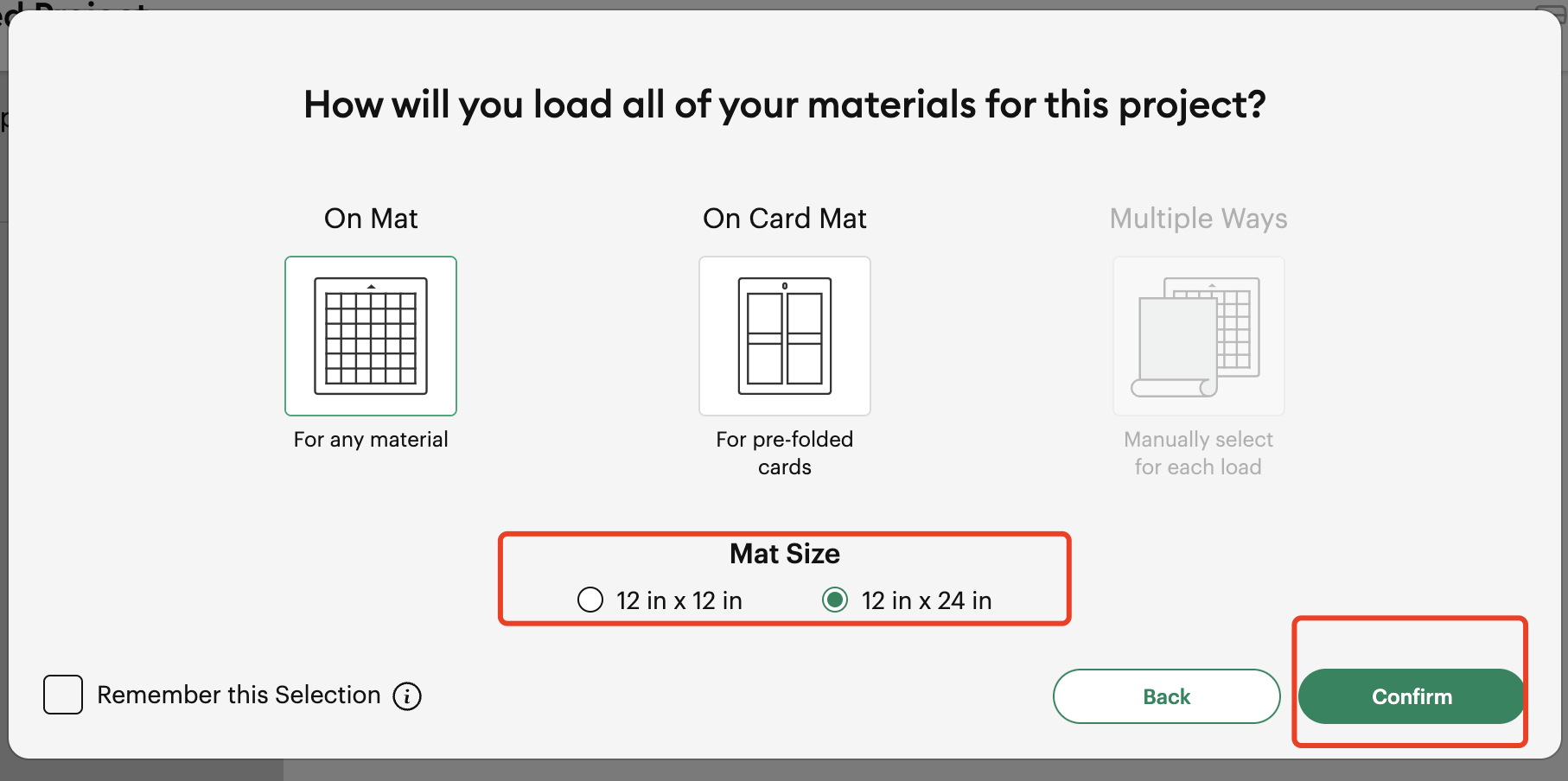
Step 8 Choose the Mat size and press “Confirm”
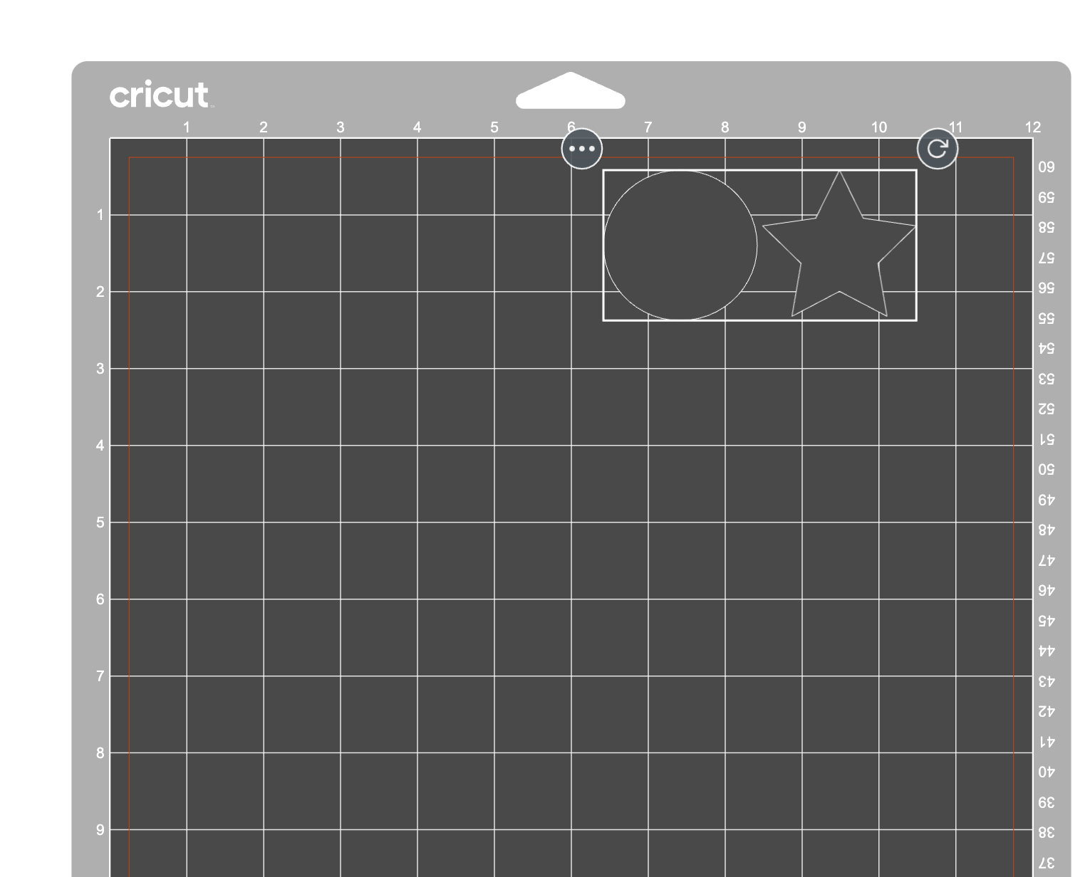
Step 9 This the view of position of the image to be cutted on the paper
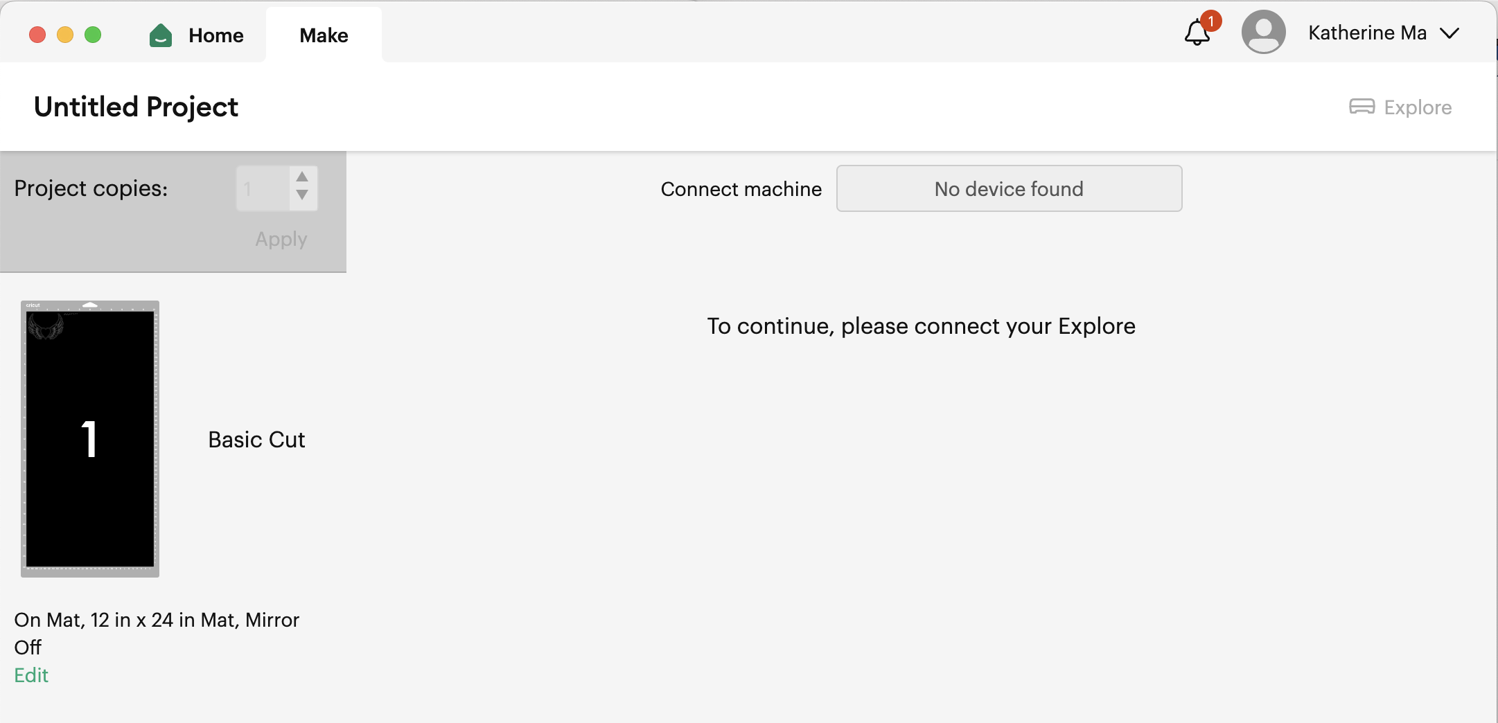
Step 10 Connect the machine to start cutting
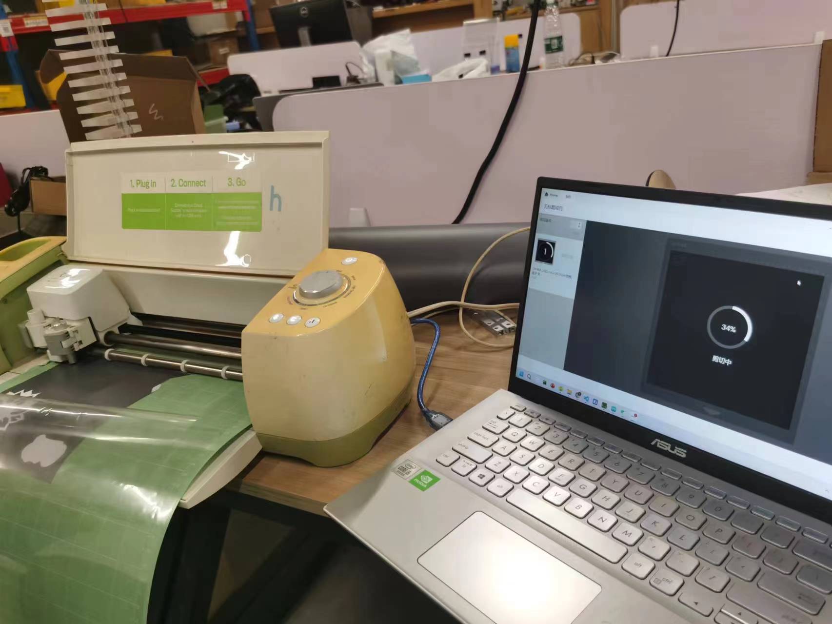
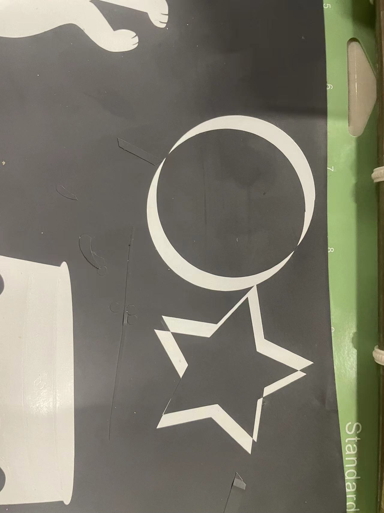
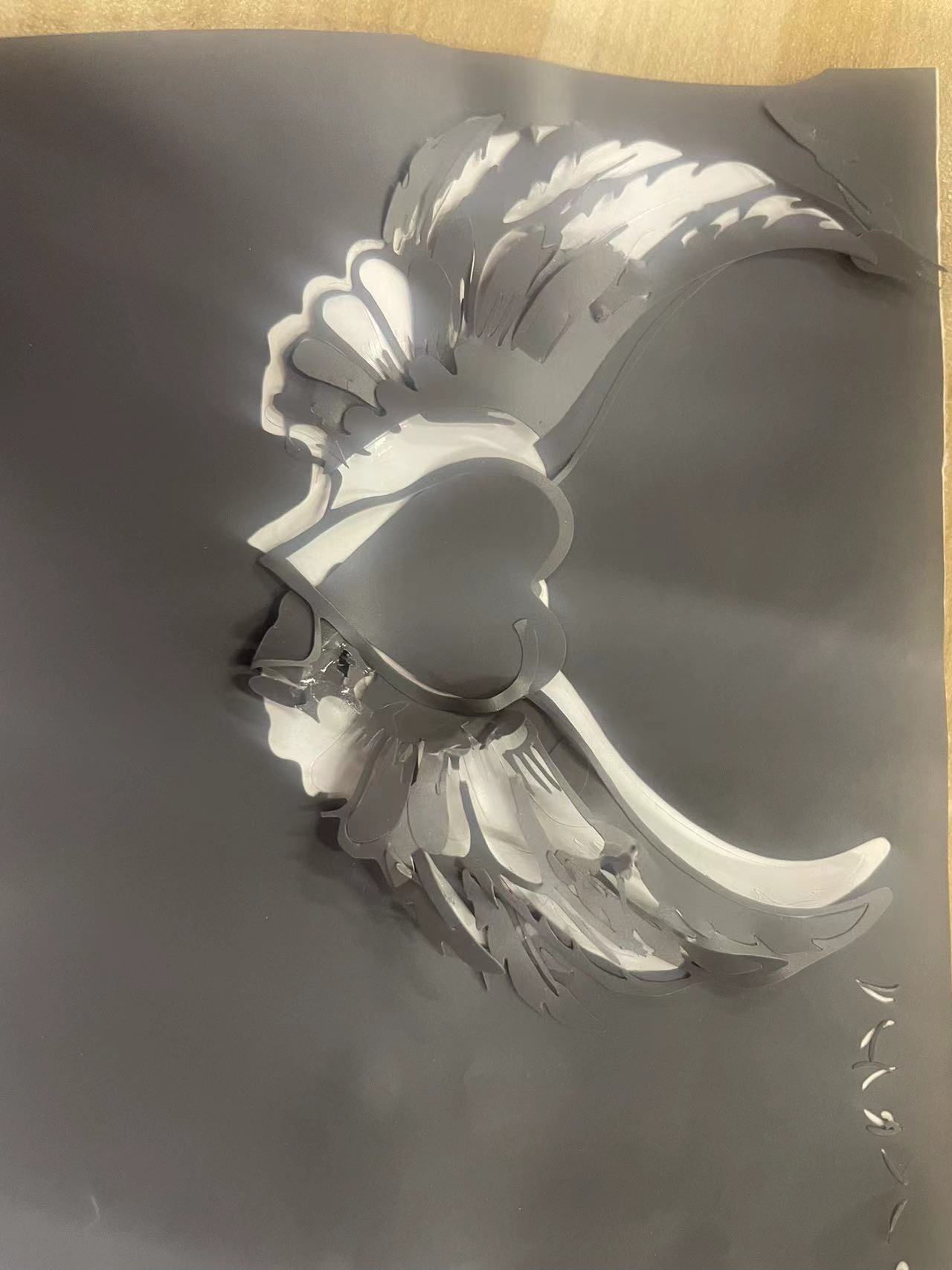
Step 11 Cutting the image
It didn't cut very well because the image is too complicated and the paper is not flat enough
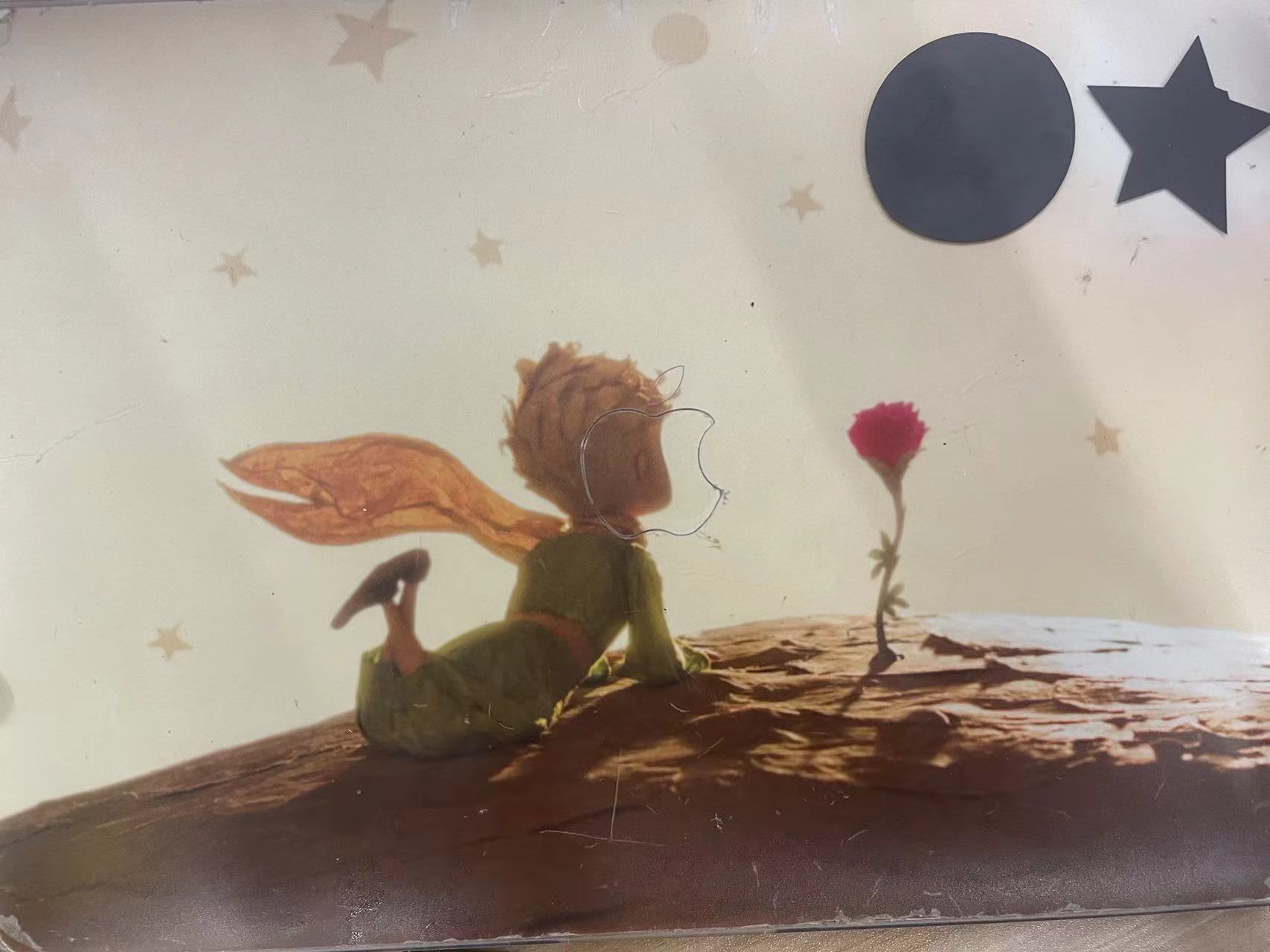
Step 12 I cutted again using the default shapes which are simpler, I chose two default shapes
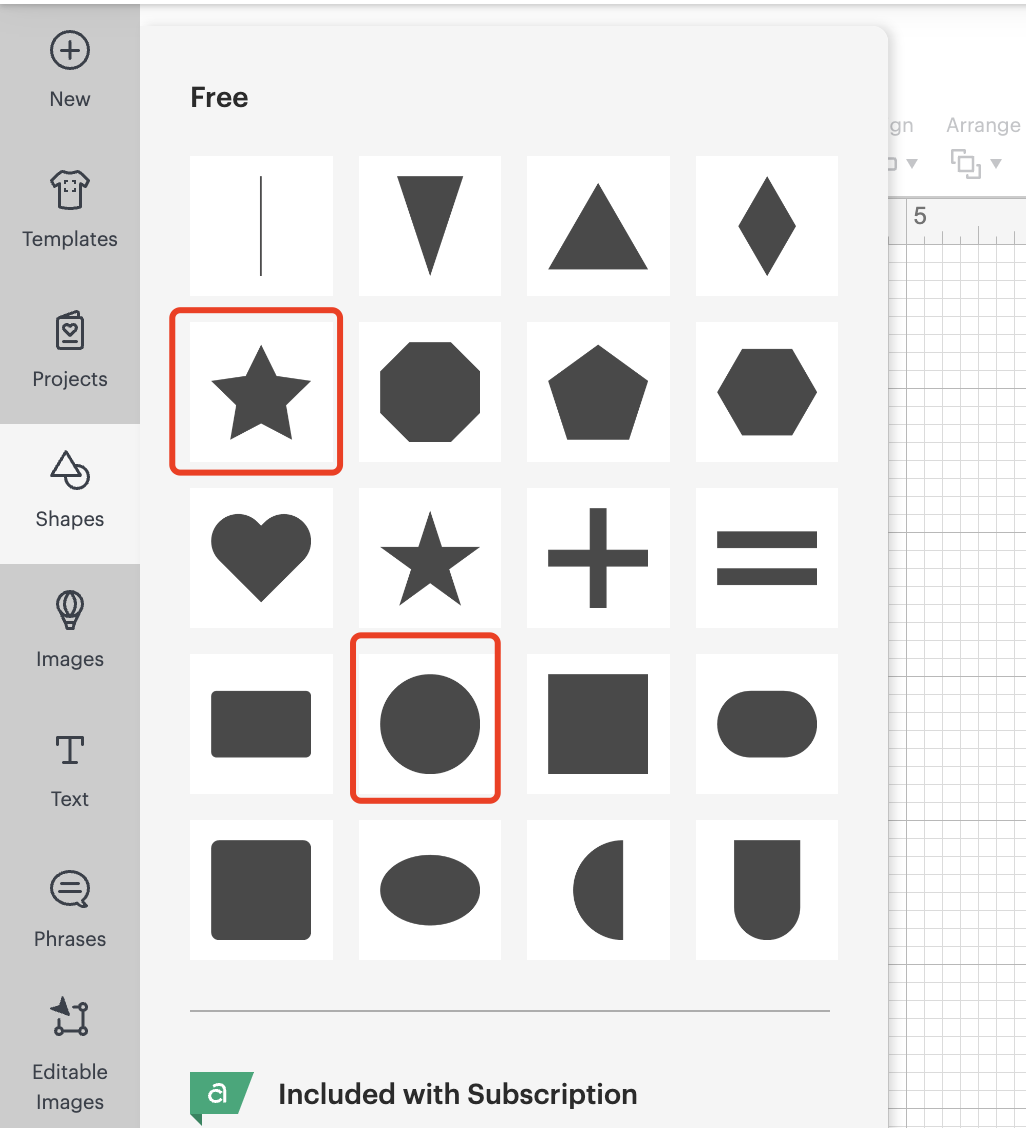
Follow the same procesures again, make the image.
Prepare to cut, choose the mat and prepare to cut.
Finally Cut.