week9. Output Devices

Group assignment:

1.Measure the power consumption of an output device. 2.Document your work on the group work page and reflect on your individual page what you learned.

  Individual assignment:

  Add an output device to a microcontroller board you’ve designed and program it to do something.

Part1 Research

Output Devices in Embedded Systems

In embedded systems, common output devices include LEDs (Light Emitting Diodes), displays, and motors.

LEDs

When programming LEDs, which are often used to indicate status or send simple signals, the following points should be noted: 1. Clearly identify the connected pins and the corresponding GPIO (General Purpose Input Output) controller. 2. Set the appropriate current and voltage to prevent LEDs from being too bright or damaged. 3. Consider energy-saving strategies to avoid unnecessary long-term lighting.

Neopixels

When working with Neopixels, the following aspects need attention:

1. Understand the communication protocol, typically a serial protocol like WS2812.

2. Manage the data transmission rate and timing to ensure accurate color and brightness control of each pixel.

3. Consider power supply requirements as a large number of Neopixels can draw significant current.

Displays

Whether it's a Liquid Crystal Display (LCD) or more advanced technologies such as OLED, the following should be taken care of when programming: 1. Understand the interface type of the display, such as SPI, I2C, or parallel interface, and correctly configure the corresponding communication parameters. 2. Handle the buffer management of images or text properly to achieve smooth display updates. 3. Based on the resolution and color depth of the display, arrange the layout and data format of the display content reasonably.

Motors

Motors are commonly used to drive mechanical components in embedded systems. Considerations when programming include: 1. Determine the type of the motor (such as DC motor, stepper motor, etc.) and the driving method. 2. Control the speed, direction, and running time of the motor precisely, and Pulse Width Modulation (PWM) technology might be required. 3. Consider the current impact during the starting and stopping processes of the motor and take appropriate protective measures.

Overall Considerations in Embedded Programming

In general, the following key issues need to be considered in embedded programming: 1. Resource limitations: Embedded systems have limited memory and processing power. It is necessary to optimize the code and data structure to reduce resource consumption. 2. Real-time requirements: Ensure that output operations can be completed within the prescribed time to meet the real-time requirements of the system. 3. Power management: Reasonably control the power usage of output devices to extend battery life or ensure stable power supply of the system. 4. Error handling: Effectively detect and handle possible hardware failures, communication errors, and other situations. 5. Compatibility: Consider the differences of different hardware platforms and operating systems to ensure the portability and compatibility of the code.

Part2 Group Assigment My Part

Using Multimeter to Measure Power Consumption of NeoPixels

I tested the power consumption situations of Neopixel lighting up 10, 30 and 60 LEDs.

NOTE : How to use Multimeter to test Neopixel's current

💡 To measure the current of Neopixel using a multimeter, here are the detailed steps to follow: 📌 Firstly, it's essential to select the appropriate range on the DC current setting of the multimeter. This should be based on the expected current magnitude. If you are unsure about the current range, it is a good idea to start with a larger one. This helps prevent damage to the multimeter and ensures accurate readings. 📌 Secondly, make sure to disconnect the circuit where the Neopixel is located. This action not only ensures your safety but also avoids any interference that could affect the measurement accuracy. 📌 Then, carefully connect the test leads of the multimeter in series into the circuit. The red lead should be placed precisely at the point where the current enters, and the black lead should be placed accurately at the point where the current exits. Incorrect connection can lead to incorrect readings or even damage to the equipment. 📌 After that, close the circuit to enable the current to pass through the multimeter smoothly. 📌 Next, pay close attention to observe and read the current value displayed on the multimeter. It's crucial to record this value accurately for your analysis or documentation. 📌 Finally, always be vigilant and avoid touching the metal parts of the test leads to prevent any potential electric shock. When measuring the current, ensure that the test leads are firmly and correctly connected to the circuit, and the range is selected appropriately to obtain precise and accurate measurement results. If you have any uncertainties or are unfamiliar with the operation, it is highly recommended to seek assistance from a professional to avoid any mistakes or risks.

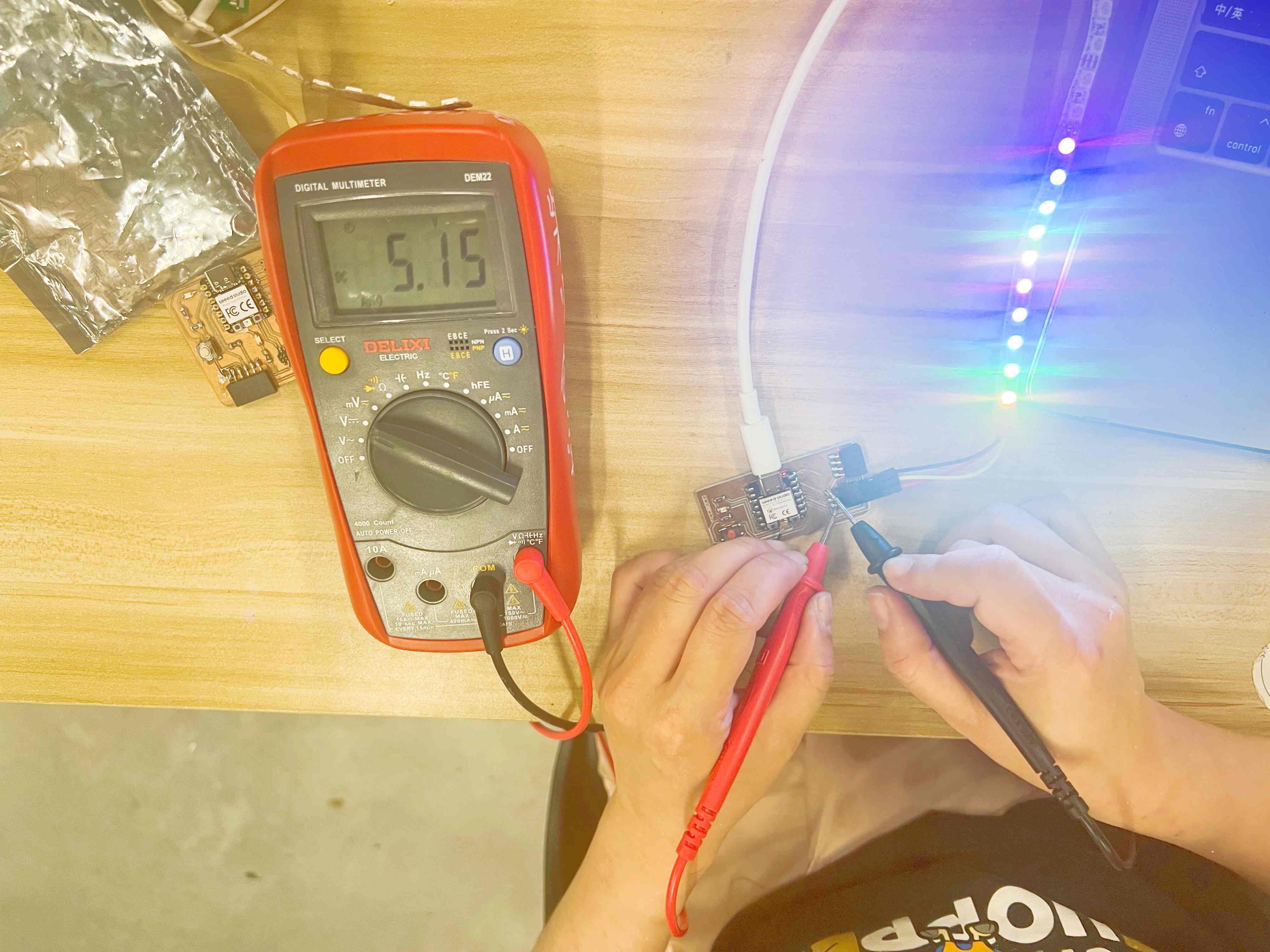
2.1 Voltage and Current of Neopixel lighting up 10 LEDs.

Description of image Description of image

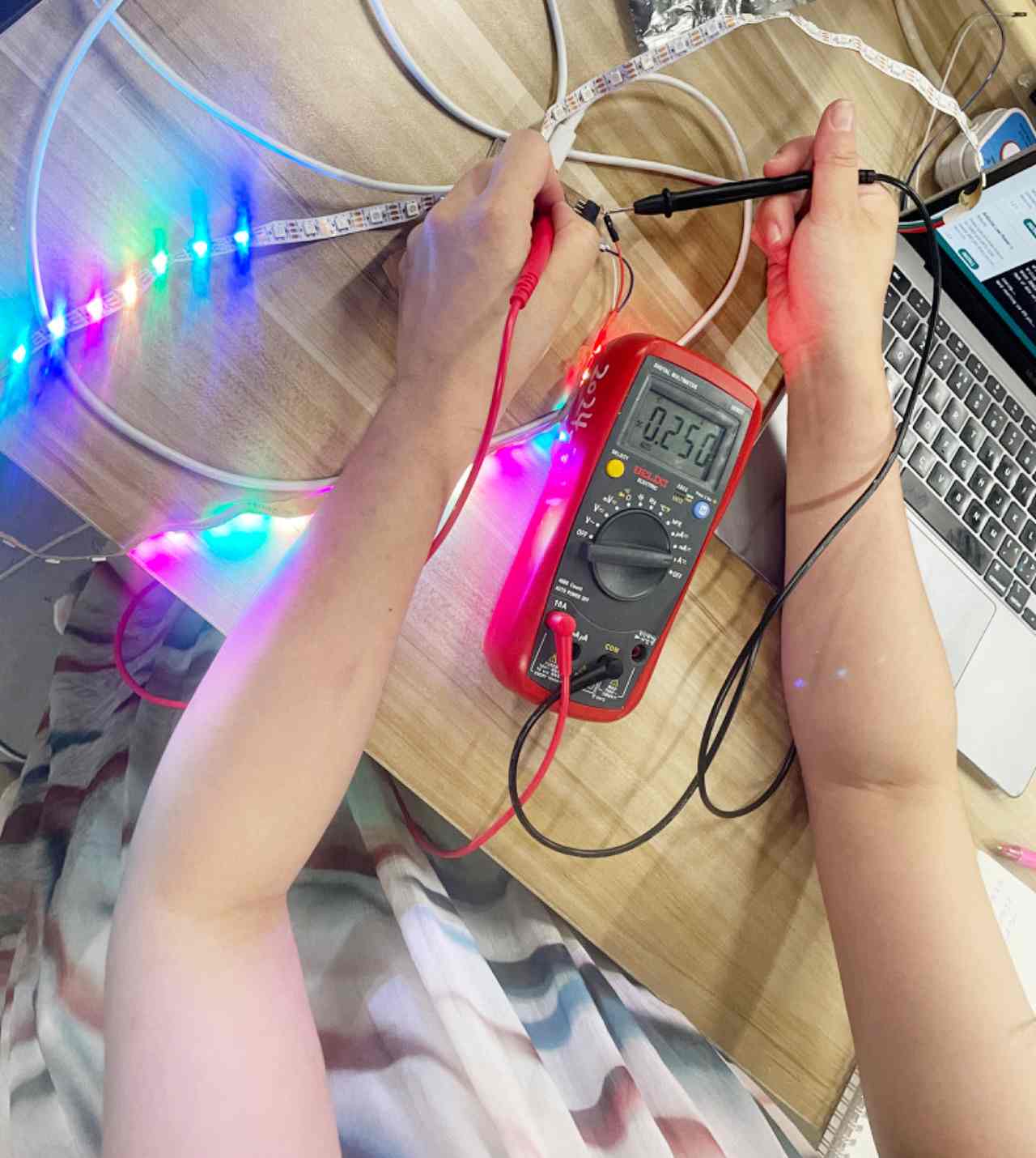
2.2 Voltage and Current of Neopixel lighting up 30 LEDs.

Description of image Description of image

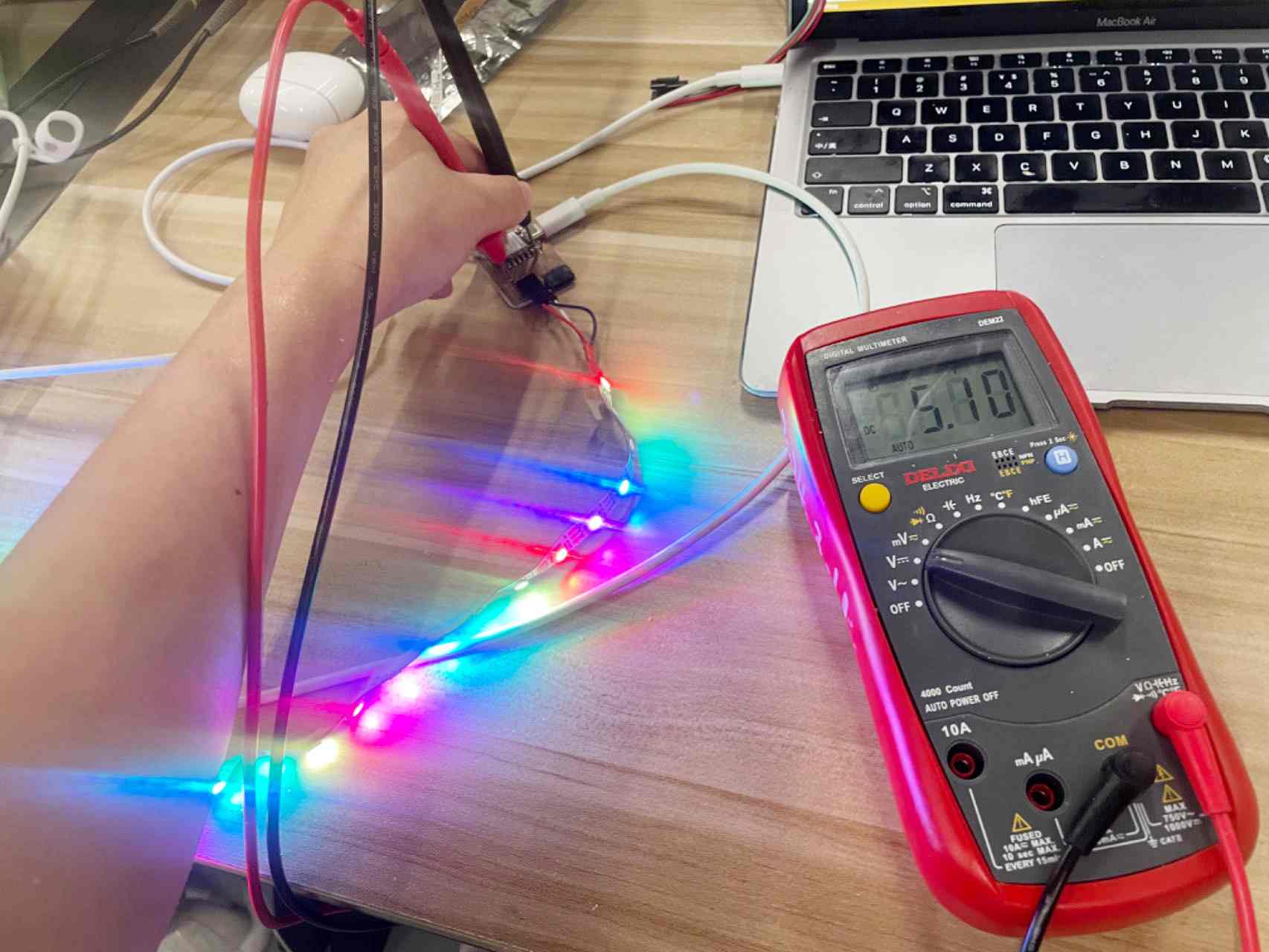
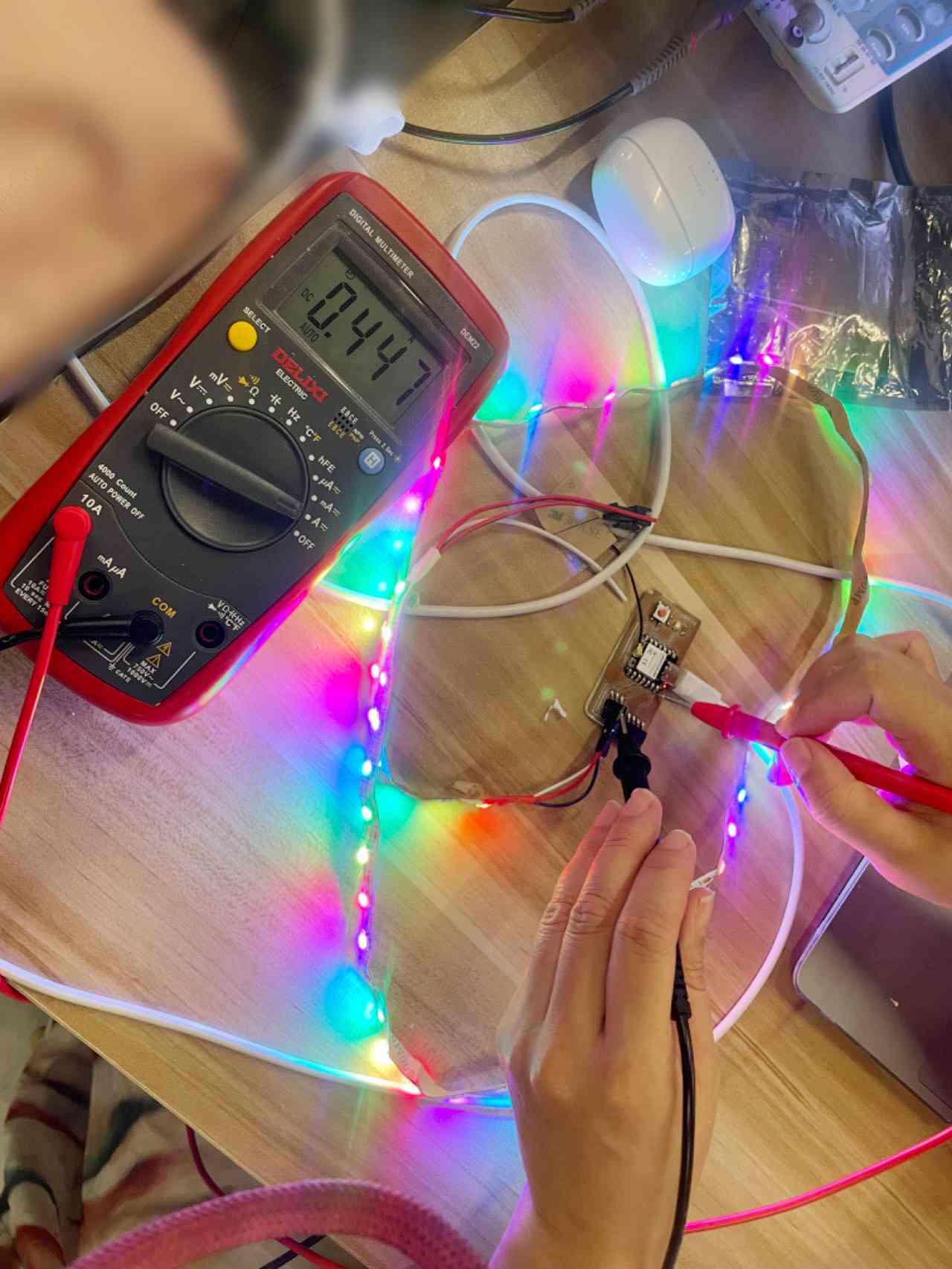
2.3 Voltage and Current of Neopixel lighting up 60 LEDs.

Description of image Description of image

2.4 Calculate the power consumption situations of Neopixel lighting up 10, 30 and 60 LEDs.


Conclusion

Based on the measured power consumption data for Neopixel lighting up different numbers of LEDs, it is evident that the power consumption increases as the number of LEDs increases. For 10 LEDs, the power consumption is 0.6273 W. When the number of LEDs rises to 30, the power consumption escalates to 1.275 W. And for 60 LEDs, the power consumption reaches 2.4327 W. This indicates a direct relationship between the number of LEDs and the power consumed. It is crucial to consider these power consumption values when designing circuits and power supply systems to ensure efficient and stable operation.

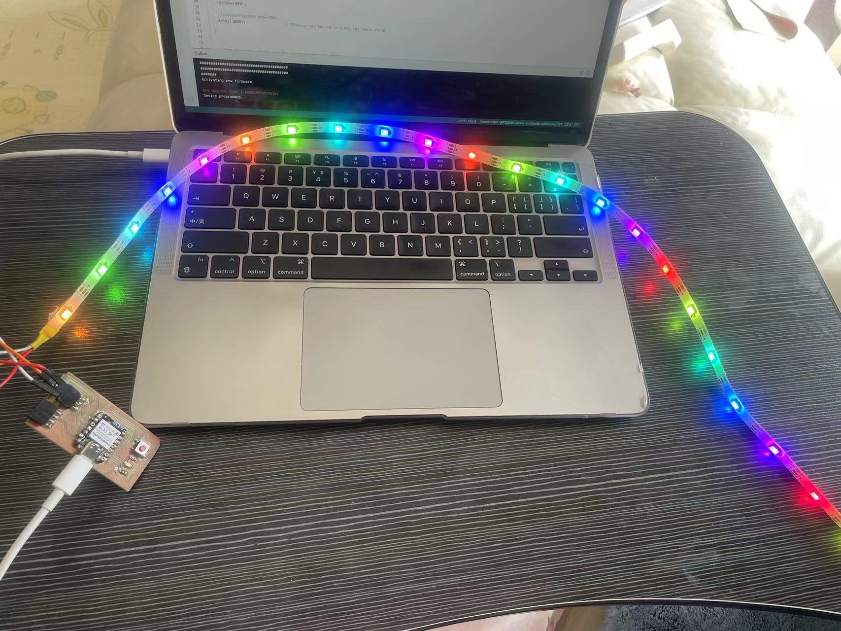
Part3 Individual Assignment

For this week's output device assignment, I chose to combine Neopixel with the PCB I designed in the week08 and solder the nRF52840 sense to achieve it. Description of image

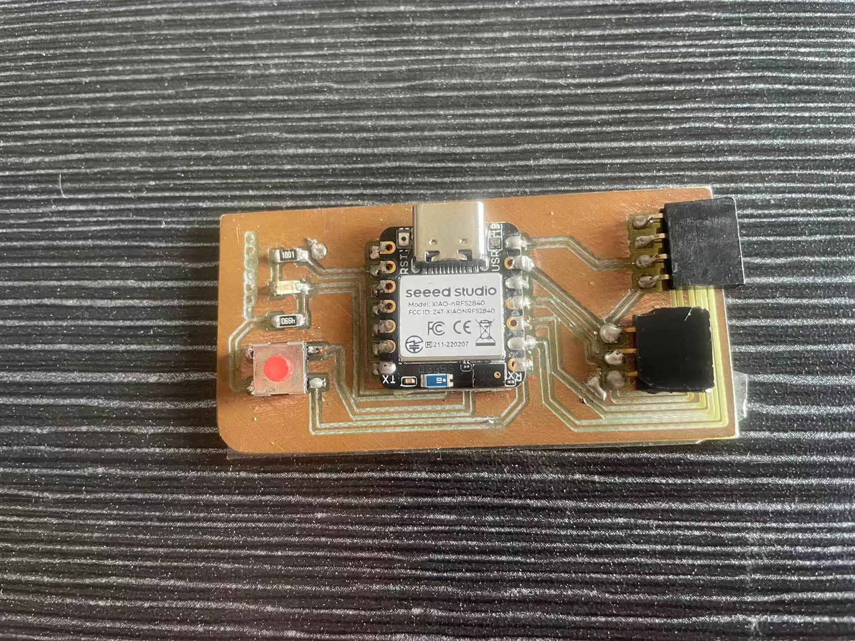
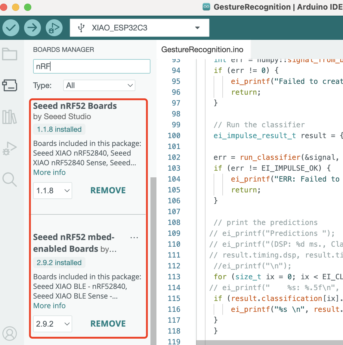
Step1. Prepare nRF52840 sense board for Arduino Programming

1. Intall the nRF52840 sense libary

For Mac, navigate to Arduino IDE > Settings, and fill "Additional Boards Manager URLs" with the url below: https://files.seeedstudio.com/arduino/package_seeeduino_boards_index.json Description of image Description of image

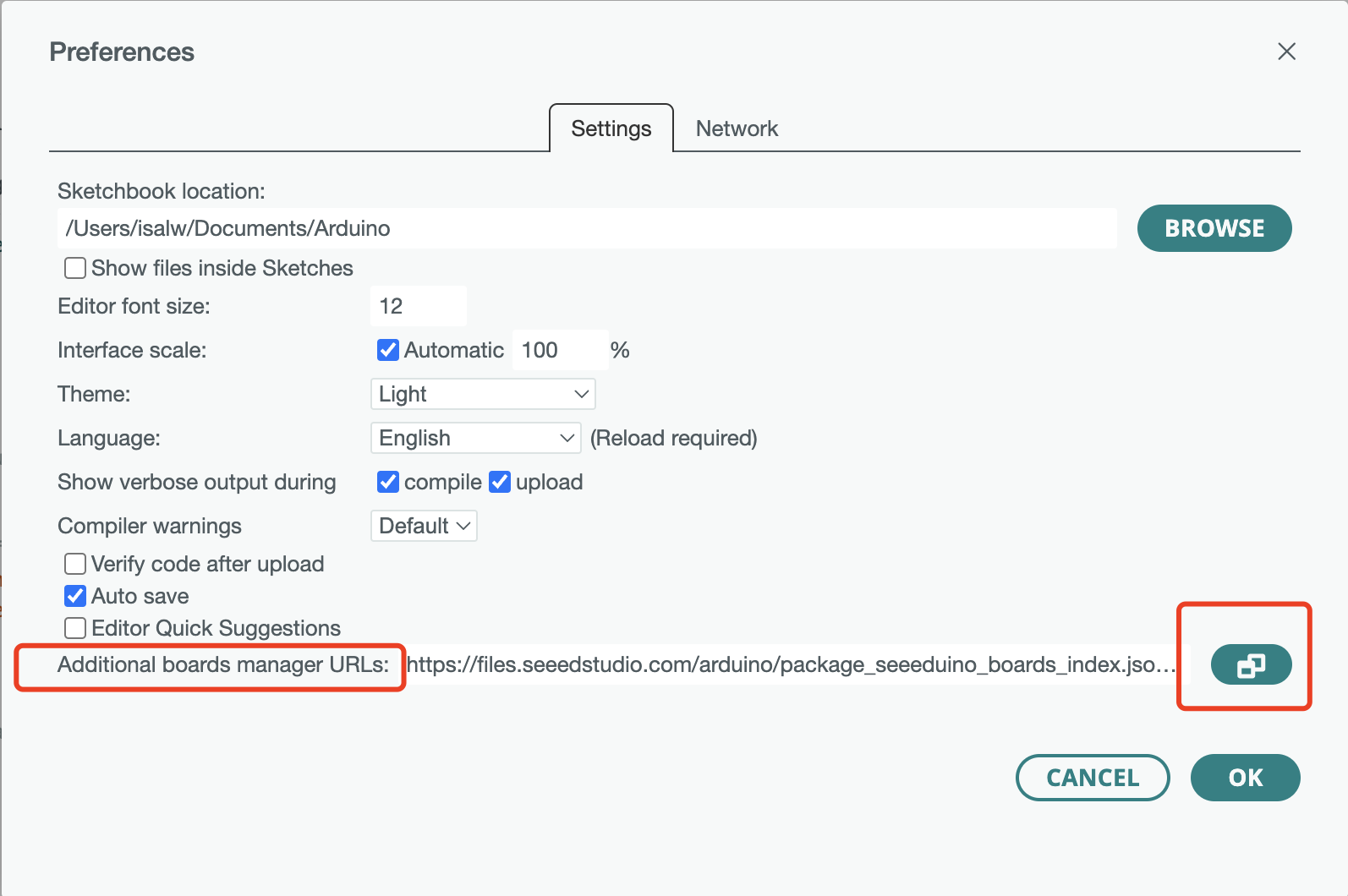
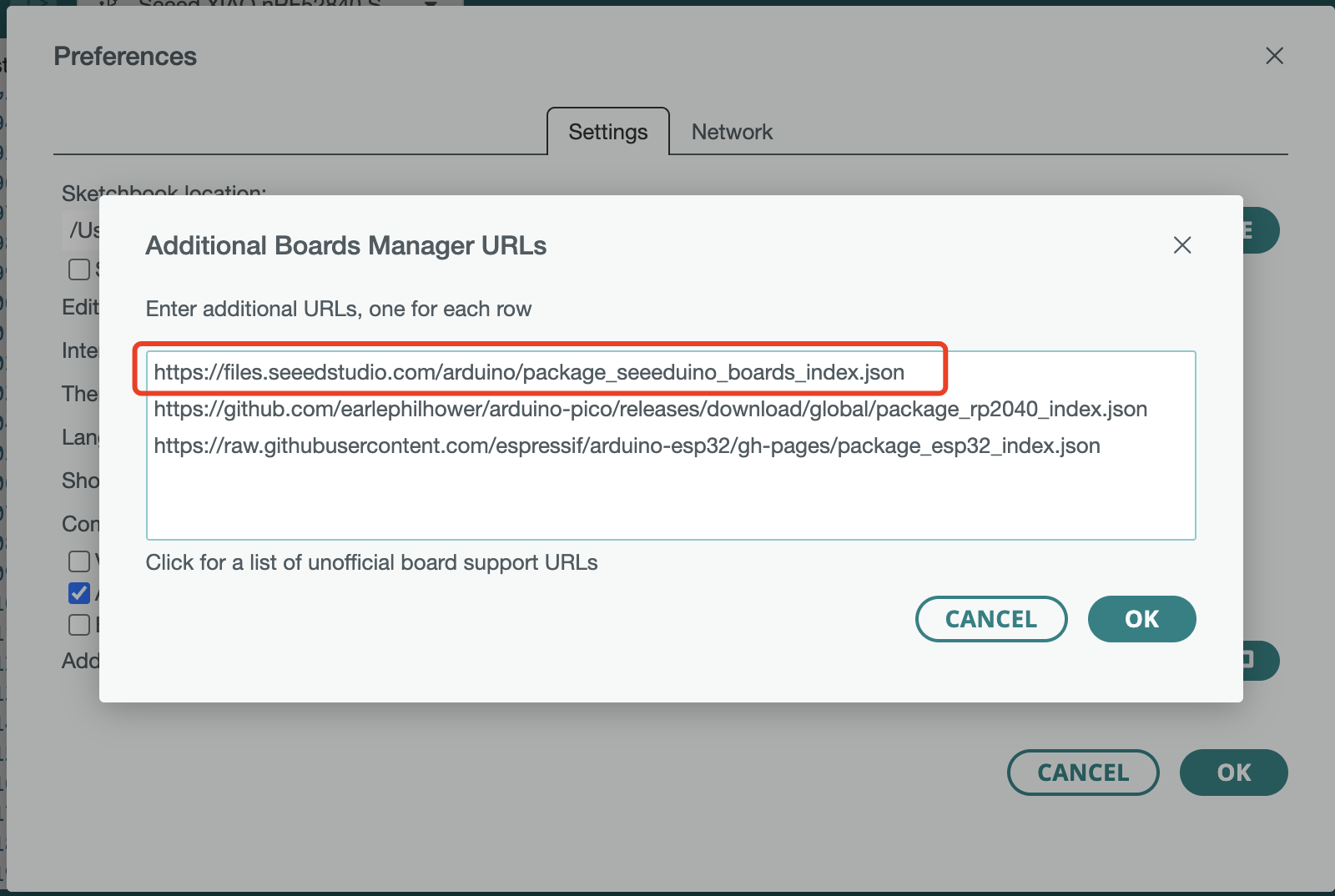
2. Intall the nRF52840 sense board manager

Navigate to Tools > Board > Boards Manager..., type the keyword "nrf52" in the search box, select the latest version of the board you want, and install it. You can install both. Description of image Description of image

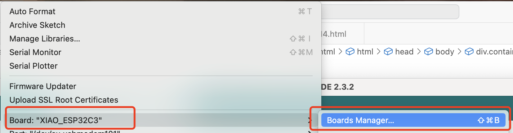
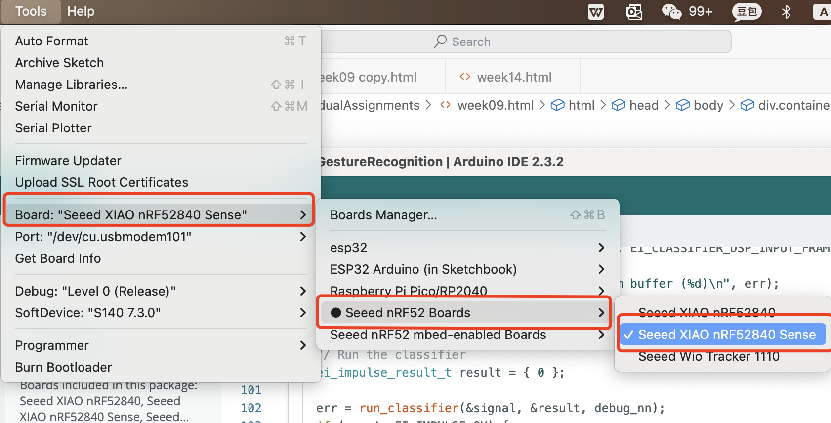
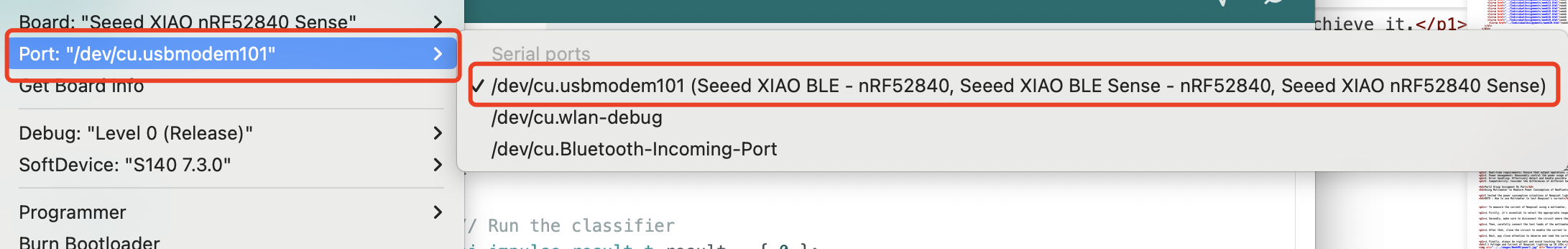
3. Select your board and port

After installing the board package, navigate to Tools > Board and choose the board you want, continue to select "Seeed XIAO nRF52840 Sense". Now we have finished setting up the Seeed Studio XIAO nRF52840 (Sense) for Arduino IDE. Description of image Description of image Description of image

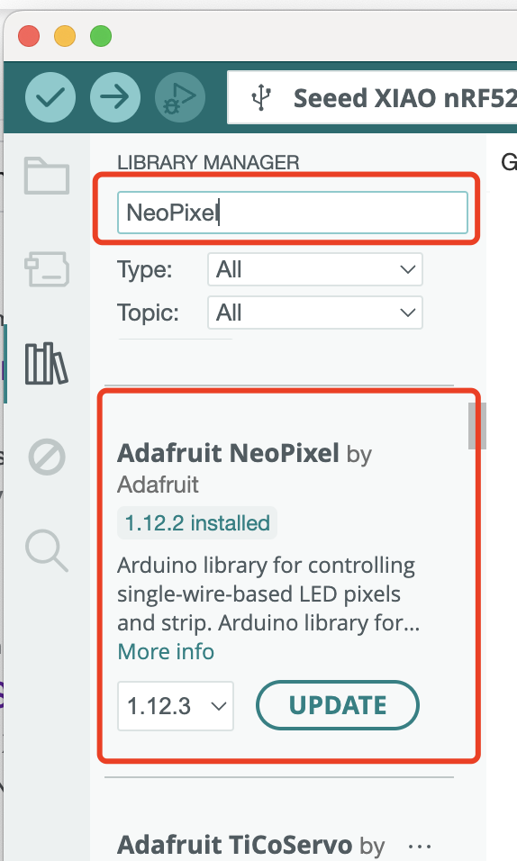
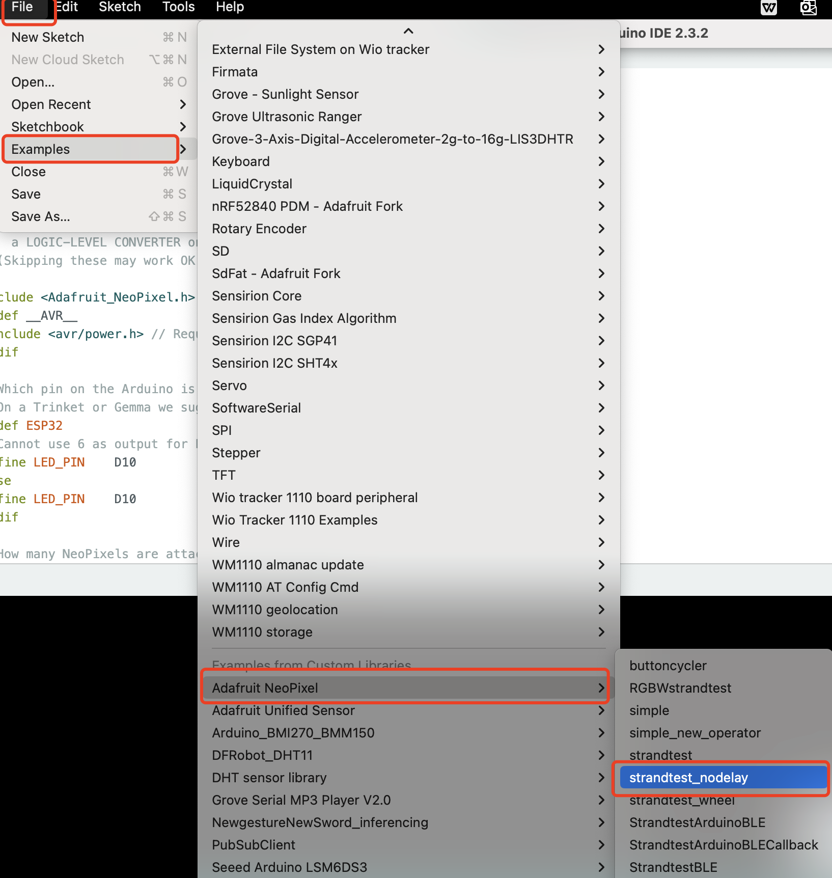
Step2. Install Neopixel libary

Description of image

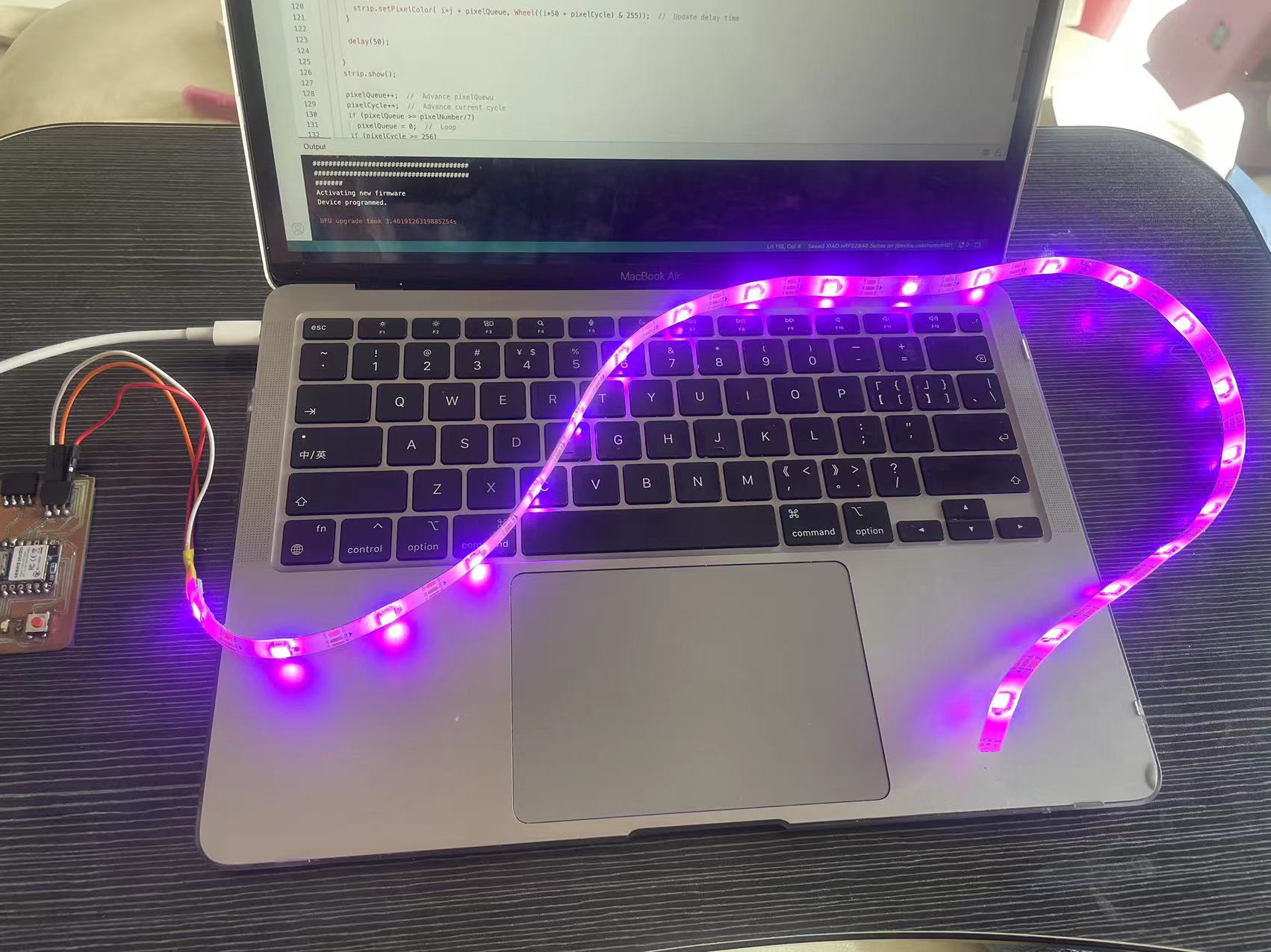
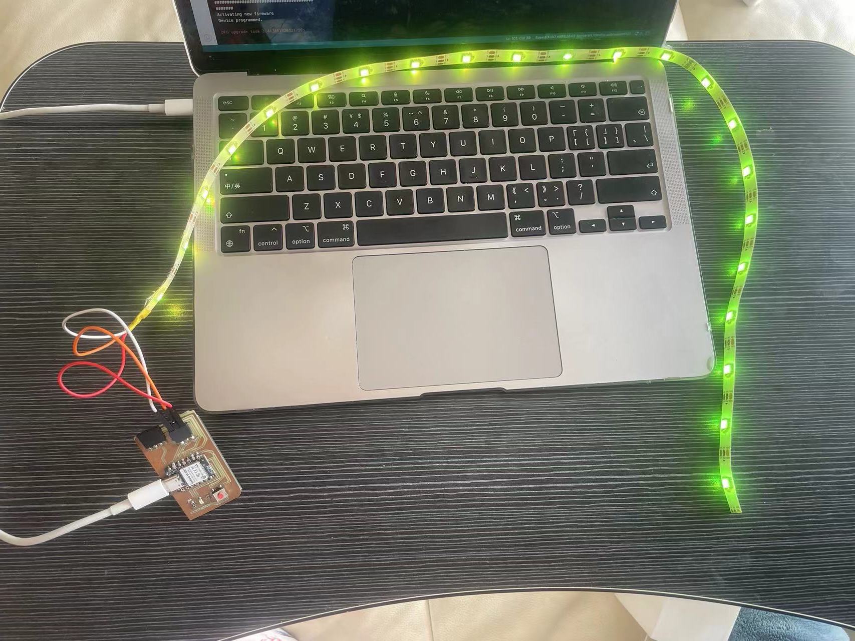
Step3. Start Programming

3.1 Code Example

There are actually many code examples in arduino after you intall the Neopixel library Description of image The code example I used was this one. I studied it and rewrite it to make my own LED effects. I have changed the LED data port according my PCB which is D10, and the LED count to be 22, which is the number of LEDs of my LED stripe.

        // A non-blocking everyday NeoPixel strip test program.

        // NEOPIXEL BEST PRACTICES for most reliable operation:
        // - Add 1000 uF CAPACITOR between NeoPixel strip's + and - connections.
        // - MINIMIZE WIRING LENGTH between microcontroller board and first pixel.
        // - NeoPixel strip's DATA-IN should pass through a 300-500 OHM RESISTOR.
        // - AVOID connecting NeoPixels on a LIVE CIRCUIT. If you must, ALWAYS
        //   connect GROUND (-) first, then +, then data.
        // - When using a 3.3V microcontroller with a 5V-powered NeoPixel strip,
        //   a LOGIC-LEVEL CONVERTER on the data line is STRONGLY RECOMMENDED.
        // (Skipping these may work OK on your workbench but can fail in the field)
        
        #include 
        #ifdef __AVR__
         #include  // Required for 16 MHz Adafruit Trinket
        #endif
        
        // Which pin on the Arduino is connected to the NeoPixels?
        // On a Trinket or Gemma we suggest changing this to 1:
        #ifdef ESP32
        // Cannot use 6 as output for ESP. Pins 6-11 are connected to SPI flash. Use 16 instead.
        #define LED_PIN    D10
        #else
        #define LED_PIN    D10
        #endif
        
        // How many NeoPixels are attached to the Arduino?
        #define LED_COUNT 60
        
        // Declare our NeoPixel strip object:
        Adafruit_NeoPixel strip(LED_COUNT, LED_PIN, NEO_GRB + NEO_KHZ800);
        // Argument 1 = Number of pixels in NeoPixel strip
        // Argument 2 = Arduino pin number (most are valid)
        // Argument 3 = Pixel type flags, add together as needed:
        //   NEO_KHZ800  800 KHz bitstream (most NeoPixel products w/WS2812 LEDs)
        //   NEO_KHZ400  400 KHz (classic 'v1' (not v2) FLORA pixels, WS2811 drivers)
        //   NEO_GRB     Pixels are wired for GRB bitstream (most NeoPixel products)
        //   NEO_RGB     Pixels are wired for RGB bitstream (v1 FLORA pixels, not v2)
        //   NEO_RGBW    Pixels are wired for RGBW bitstream (NeoPixel RGBW products)
        
        unsigned long pixelPrevious = 0;        // Previous Pixel Millis
        unsigned long patternPrevious = 0;      // Previous Pattern Millis
        int           patternCurrent = 0;       // Current Pattern Number
        int           patternInterval = 5000;   // Pattern Interval (ms)
        bool          patternComplete = false;
        
        int           pixelInterval = 50;       // Pixel Interval (ms)
        int           pixelQueue = 0;           // Pattern Pixel Queue
        int           pixelCycle = 0;           // Pattern Pixel Cycle
        uint16_t      pixelNumber = LED_COUNT;  // Total Number of Pixels
        
        // setup() function -- runs once at startup --------------------------------
        void setup() {
          // These lines are specifically to support the Adafruit Trinket 5V 16 MHz.
          // Any other board, you can remove this part (but no harm leaving it):
        #if defined(__AVR_ATtiny85__) && (F_CPU == 16000000)
          clock_prescale_set(clock_div_1);
        #endif
          // END of Trinket-specific code.
        
          strip.begin();           // INITIALIZE NeoPixel strip object (REQUIRED)
          strip.show();            // Turn OFF all pixels ASAP
          strip.setBrightness(50); // Set BRIGHTNESS to about 1/5 (max = 255)
        }
        
        // loop() function -- runs repeatedly as long as board is on ---------------
        void loop() {
          unsigned long currentMillis = millis();                     //  Update current time
          if( patternComplete || (currentMillis - patternPrevious) >= patternInterval) {  //  Check for expired time
            patternComplete = false;
            patternPrevious = currentMillis;
            patternCurrent++;                                         //  Advance to next pattern
            if(patternCurrent >= 7)
              patternCurrent = 0;
          }
        
          if(currentMillis - pixelPrevious >= pixelInterval) {        //  Check for expired time
            pixelPrevious = currentMillis;                            //  Run current frame
            switch (patternCurrent) {
              case 7:
                theaterChaseRainbow(50); // Rainbow-enhanced theaterChase variant
                break;
              case 6:
                rainbow(10); // Flowing rainbow cycle along the whole strip
                break;     
              case 5:
                theaterChase(strip.Color(0, 0, 127), 50); // Blue
                break;
              case 4:
                theaterChase(strip.Color(127, 0, 0), 50); // Red
                break;
              case 3:
                theaterChase(strip.Color(127, 127, 127), 50); // White
                break;
              case 2:
                colorWipe(strip.Color(0, 0, 255), 50); // Blue
                break;
              case 1:
                colorWipe(strip.Color(0, 255, 0), 50); // Green
                break;        
              default:
                colorWipe(strip.Color(255, 0, 0), 50); // Red
                break;
            }
          }
        }
        
        // Some functions of our own for creating animated effects -----------------
        
        // Fill strip pixels one after another with a color. Strip is NOT cleared
        // first; anything there will be covered pixel by pixel. Pass in color
        // (as a single 'packed' 32-bit value, which you can get by calling
        // strip.Color(red, green, blue) as shown in the loop() function above),
        // and a delay time (in milliseconds) between pixels.
        void colorWipe(uint32_t color, int wait) {
          static uint16_t current_pixel = 0;
          pixelInterval = wait;                        //  Update delay time
          strip.setPixelColor(current_pixel++, color); //  Set pixel's color (in RAM)
          strip.show();                                //  Update strip to match
          if(current_pixel >= pixelNumber) {           //  Loop the pattern from the first LED
            current_pixel = 0;
            patternComplete = true;
          }
        }
        
        // Theater-marquee-style chasing lights. Pass in a color (32-bit value,
        // a la strip.Color(r,g,b) as mentioned above), and a delay time (in ms)
        // between frames.
        void theaterChase(uint32_t color, int wait) {
          static uint32_t loop_count = 0;
          static uint16_t current_pixel = 0;
        
          pixelInterval = wait;                   //  Update delay time
        
          strip.clear();
        
          for(int c=current_pixel; c < pixelNumber; c += 3) {
            strip.setPixelColor(c, color);
          }
          strip.show();
        
          current_pixel++;
          if (current_pixel >= 3) {
            current_pixel = 0;
            loop_count++;
          }
        
          if (loop_count >= 10) {
            current_pixel = 0;
            loop_count = 0;
            patternComplete = true;
          }
        }
        
        // Rainbow cycle along whole strip. Pass delay time (in ms) between frames.
        void rainbow(uint8_t wait) {
          if(pixelInterval != wait)
            pixelInterval = wait;                   
          for(uint16_t i=0; i < pixelNumber; i++) {
            strip.setPixelColor(i, Wheel((i + pixelCycle) & 255)); //  Update delay time  
          }
          strip.show();                             //  Update strip to match
          pixelCycle++;                             //  Advance current cycle
          if(pixelCycle >= 256)
            pixelCycle = 0;                         //  Loop the cycle back to the begining
        }
        
        //Theatre-style crawling lights with rainbow effect
        void theaterChaseRainbow(uint8_t wait) {
          if(pixelInterval != wait)
            pixelInterval = wait;                   //  Update delay time  
          for(int i=0; i < pixelNumber; i+=3) {
            strip.setPixelColor(i + pixelQueue, Wheel((i + pixelCycle) % 255)); //  Update delay time  
          }
          strip.show();
          for(int i=0; i < pixelNumber; i+=3) {
            strip.setPixelColor(i + pixelQueue, strip.Color(0, 0, 0)); //  Update delay time  
          }      
          pixelQueue++;                           //  Advance current queue  
          pixelCycle++;                           //  Advance current cycle
          if(pixelQueue >= 3)
            pixelQueue = 0;                       //  Loop
          if(pixelCycle >= 256)
            pixelCycle = 0;                       //  Loop
        }
        
        // Input a value 0 to 255 to get a color value.
        // The colours are a transition r - g - b - back to r.
        uint32_t Wheel(byte WheelPos) {
          WheelPos = 255 - WheelPos;
          if(WheelPos < 85) {
            return strip.Color(255 - WheelPos * 3, 0, WheelPos * 3);
          }
          if(WheelPos < 170) {
            WheelPos -= 85;
            return strip.Color(0, WheelPos * 3, 255 - WheelPos * 3);
          }
          WheelPos -= 170;
          return strip.Color(WheelPos * 3, 255 - WheelPos * 3, 0);
        }


3.2 Learn about the "colorWipe" Function


  void colorWipe(uint32_t color, int wait) {
    static uint16_t current_pixel = 0;
    pixelInterval = wait;                        //  Update delay time
    strip.setPixelColor(current_pixel++, color); //  Set pixel's color (in RAM)
    strip.show();                                //  Update strip to match
    if(current_pixel >= pixelNumber) {           //  Loop the pattern from the first LED
      current_pixel = 0;
      patternComplete = true;
    }
  }


Explaination of Function colorWipe:

 • This function has two parameters: color and wait.  • The color parameter specifies the color that will be set for each pixel as the function progresses. The data type is uint32_t, which means it is a 32-bit integer type. Since the RGB code is 32 bits, each eight bits represent Red, Green, and Blue.  • The wait parameter determines the amount of time to wait before moving on to the next pixel. This controls the speed or pace at which the color wipe effect occurs.  • Inside the function, a static variable current_pixel is declared and initialized to 0. This variable keeps track of the current pixel position.  • The pixelInterval is updated with the provided wait value.  • The setPixelColor method is used to set the color of the current pixel (indicated by current_pixel) to the specified color. Then, current_pixel is incremented by 1.  • The show method is called to update the physical LED strip to reflect the changes made in RAM.  • Finally, there is a check to see if current_pixel has reached or exceeded the total number of pixels (pixelNumber). If so, current_pixel is reset to 0 and a flag patternComplete is set to true, indicating that the pattern has looped back to the beginning.  • To call the colorWipe function, the color needs to use stipe.Color(valueofRed, valueOfGreen, valueOfBlue), the wait time is an simple integer in ms unit.

  colorWipe(strip.Color( 255, 0, 255), 30);   //wipe purple
  
Description of image

3.3 Learn about the "rainbow" Function


  void rainbow(uint8_t wait) {
    if(pixelInterval != wait)
      pixelInterval = wait;                   
    for(uint16_t i=0; i < pixelNumber; i++) {
      strip.setPixelColor(i, Wheel((i + pixelCycle) & 255)); //  Update delay time  
    }
    strip.show();                             //  Update strip to match
    pixelCycle++;                             //  Advance current cycle
    if(pixelCycle >= 256)
      pixelCycle = 0;                         //  Loop the cycle back to the begining
  }

When I first ran the rainbow function, it appeared like colorWipe, which was not what I had imagined it to be – rainbow colors. Then I studied the code carefully and reproduced the rainbow code I imagined.. Description of image

The reason is that:

In the code strip.setPixelColor(i, Wheel((i + pixelCycle) & 255));: Because i increments by only 1 each time, the color change also increments by only 1,so it is like change from Red243 to Red244,which is not obvious enough.

Explaination of Function rainbow:

 • First, it checks if the pixelInterval is not equal to the provided wait. If so, it updates pixelInterval with the wait value.  • Then, it uses a loop to set the color of each pixel from 0 to pixelNumber. The color is determined by the Wheel function based on the sum of the pixel index i and the pixelCycle, masked by 255.  • After setting the colors, it calls the show method to update the physical LED strip to display the colors.  • Finally, it increments the pixelCycle. If pixelCycle exceeds 255, it resets it to 0 to start the cycle again. So the rainbow effect can demonstrate different color in different cycle, but just in each cycle the color effect is just like colorWipe.  • To call the rainbow function, only needs the wait time is an simple integer in ms unit.

  rainbow(500);

3.4 Learn about functionWheel


    uint32_t Wheel(byte WheelPos) {
      WheelPos = 255 - WheelPos;
      if(WheelPos < 85) {
        return strip.Color(255 - WheelPos * 3, 0, WheelPos * 3);
      }
      if(WheelPos < 170) {
        WheelPos -= 85;
        return strip.Color(0, WheelPos * 3, 255 - WheelPos * 3);
      }
      WheelPos -= 170;
      return strip.Color(WheelPos * 3, 255 - WheelPos * 3, 0);
    }
  
  
First, it modifies the input WheelPos by subtracting it from 255. Then based on the different value of the WheelPos to transfer it to different color value. I did the calculations by myself. When substituting different values of WheelPos within different ranges, different ranges of color changes will be produced. Description of image

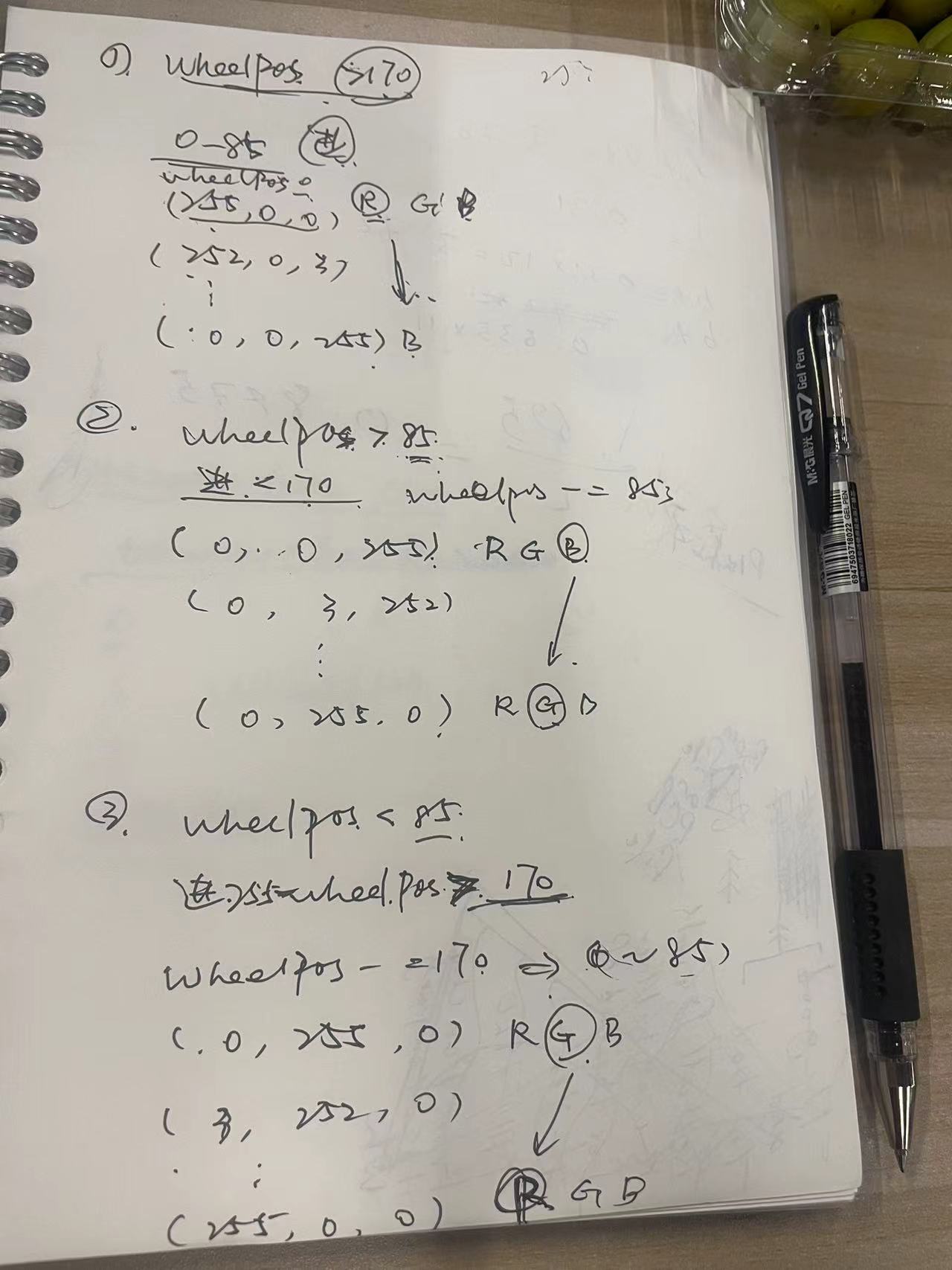
Explaination of FunctionWheel

• First, it modifies the input WheelPos by subtracting it from 255. • Then, it checks if WheelPos is less than 85. If so, it returns a color composed of 255 - WheelPos * 3 for the red component, 0 for the green component, and WheelPos * 3 for the blue component. • If WheelPos is not less than 85 but less than 170, it subtracts 85 from WheelPos and returns a color with 0 for the red component, WheelPos * 3 for the green component, and 255 - WheelPos * 3 for the blue component. • If WheelPos is greater than or equal to 170, it subtracts 170 from WheelPos and returns a color with WheelPos * 3 for the red component, 255 - WheelPos * 3 for the green component, and 0 for the blue component.

3.5 ReWrite function rainbow:

I want to see the rainbow color of the LED in one cycle, so I changed to code of the Wheel Part, to make bigger diffrence,by changing i to i*50:

    for(uint16_t i=0; i < pixelNumber; i++) {
      strip.setPixelColor(i, Wheel((i*50 + pixelCycle) & 255)); //  Update delay time  
    }
  
  
Finally, I got the rainbow I have imagined! And if you still want continous color but not too much, set i to be i*20 will be better. Description of image

3.6 Learn about function theaterChaseRainbow

The example code is as below:

    void theaterChaseRainbow(uint8_t wait) {
      if(pixelInterval != wait)
        pixelInterval = wait;                   //  Update delay time  
      for(int i=0; i < pixelNumber; i+=3) {
        strip.setPixelColor(i + pixelQueue, Wheel((i + pixelCycle) % 255)); //  Update delay time  
      }
      strip.show();
      for(int i=0; i < pixelNumber; i+=3) {
        strip.setPixelColor(i + pixelQueue, strip.Color(0, 0, 0)); //  Update delay time  
      }      
      pixelQueue++;                           //  Advance current queue  
      pixelCycle++;                           //  Advance current cycle
      if(pixelQueue >= 3)
        pixelQueue = 0;                       //  Loop
      if(pixelCycle >= 256)
        pixelCycle = 0;                       //  Loop
    }
  
  
Because of the same reason as function rainbow, the input parameter i of Wheel changes only by 1 each time. So the effect of this theaterChaseRainbow is also that the color change is very insignificant. It takes about 15 seconds for a significant color change.

Explaination of Function theaterChaseRainbow

• First, it checks if pixelInterval is not equal to the provided wait. If not, it updates pixelInterval with wait. • Then, it uses a loop to set the color of pixels at positions incremented by 3 from 0 to pixelNumber. The color is determined by the Wheel function based on the sum of the pixel index i and pixelCycle, modulo 255. • After that, it calls strip.show to display the updated colors. • Another loop is used to set the color of pixels to black at positions incremented by 3. pixelQueue is incremented. If it exceeds 3, it is reset to 0 to create a looping effect. pixelCycle is also incremented. If it exceeds 256, it is reset to 0 to create a looping effect. Because my LED strip has 22 LEDs, I want to try to light it up in three sections respectively, and the starting colors of these three sections are all different, but within each section, the colors are gradient. So I modified the code as below:

      void theaterChaseRainbow(uint8_t wait) {
        if (pixelInterval != wait)
          pixelInterval = wait;  //  Update delay time
        for (int i = 0 ; i < pixelNumber; i += 7) {
          for(int j = 0; j <= i%7 ; j++){
            
            strip.setPixelColor( i+j + pixelQueue, Wheel((i*50 + pixelCycle) & 255));  //  Update delay time
          }
         
          delay(50);
          
        }
        strip.show();
    
        pixelQueue++;  //  Advance pixelQuewu
        pixelCycle++;  //  Advance current cycle
        if (pixelQueue >= pixelNumber/7)
          pixelQueue = 0;  //  Loop
        if (pixelCycle >= 256)
          pixelCycle = 0;  //  Loop
      }


Explaination of my theaterChaseRainbow

• Step size change:
  Originally, the pixels were processed with a step size of 3 (i += 3), but now it is changed to a step size of 7 (i += 7). This means that the pixel interval processed in each loop is larger. • Introduction of nested loop:
  For each step position i, through the internal for loop (for(int j = 0; j <= i%7 ; j++)), j LEDs in each section of the LED are simultaneously lit and incremented. • Addition of delay:
  After processing each group of pixels (the position i determined by the outer loop and the related pixels processed by the inner loop), a delay of 50 milliseconds (delay(50)) is added. This makes the effect clearer.

My Final theaterChaseRainbow effect

  KK Rocks!