Weekly assignments
- week 1. Project Management
- week 2. Computer Aided Design
- week 3. Computer Controlled Cutting
- week 4. Electronics Production
- week 5. 3D Scanning and Printing
- week 6. Embeded Programming
- week 7. Computer Controlled Machining
- week 8. Electronics Design
- week 9. Output Devices
- week 10. Mechanical design & Machine Design
- week 11. Break & Midterm Review
- week 12. Input devices
- week 13. Moulding and Casting
- week 14. Networking and communications
- week 15. Interface and application programming
- week 16. Wildcard week
- week 17. Applications And implications
- week 18. Project Development
- week 19. Invention, Intellectual Property and Income
Week7. Computer Controlled Machining
Group assignment:
Individual assignment:
- Make (design+mill+assemble) something big (~meter-scale)- extra credit: don't use fasteners or glue
- extra credit: include curved surfaces
1. Group Assignment My Part
Safety Training
Emergency Procedures:
Machine Safety:
Machine Setup
Test Runout and Alignment:
Fixturing and Workholding:
Material Preparation:
Operational Procedures
Speeds and Feeds:
Toolpaths:
Coolant and Lubrication:
Machine Maintenance:
2. Individual Assigment
The assignment for this week is to make a piece of furniture using a large CNC machine. So, I want to make a small bookshelf for storing books.
Inspirtion and Preparation
01 I was inspired by the bookshelf online and decided to make one for myself
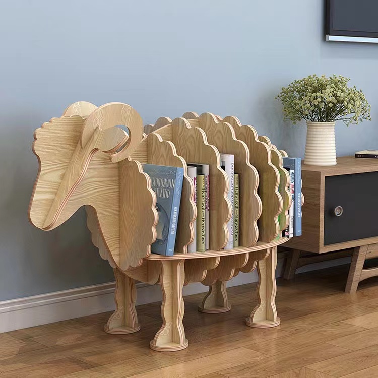
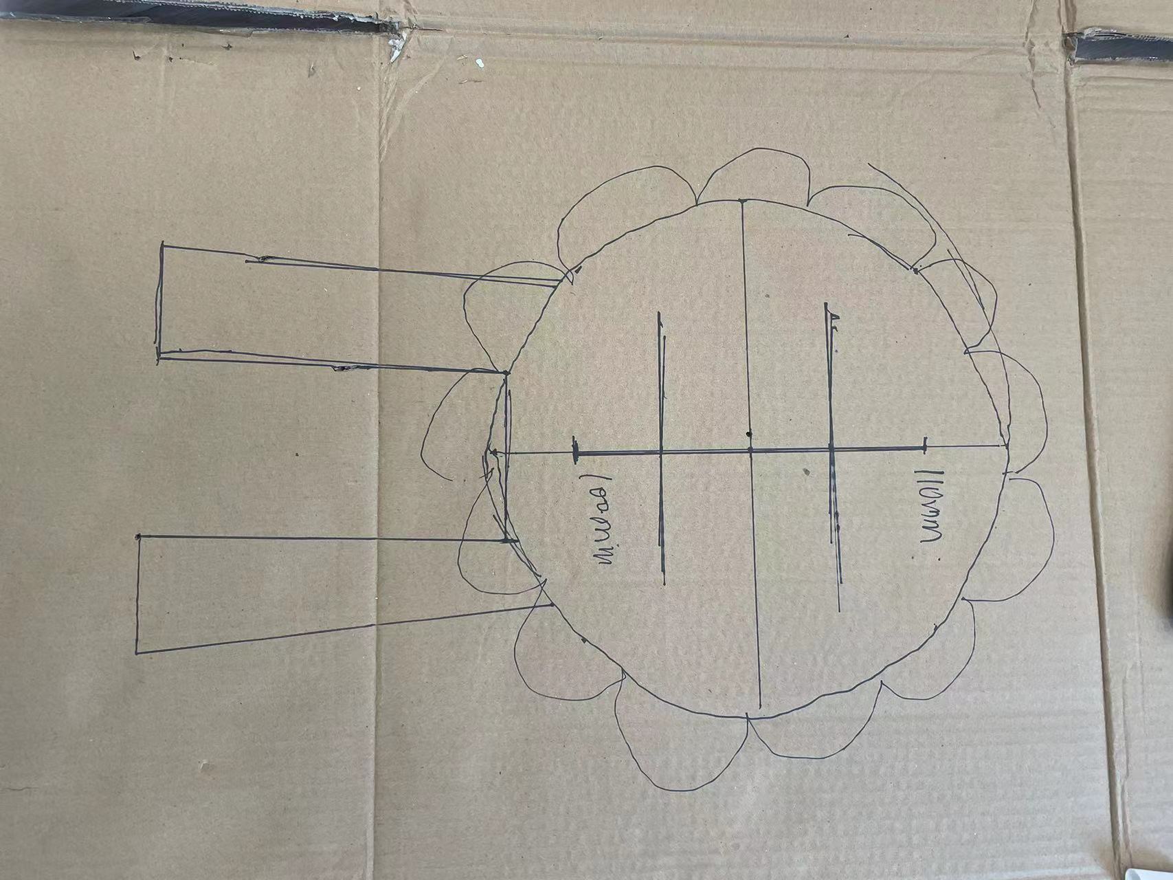
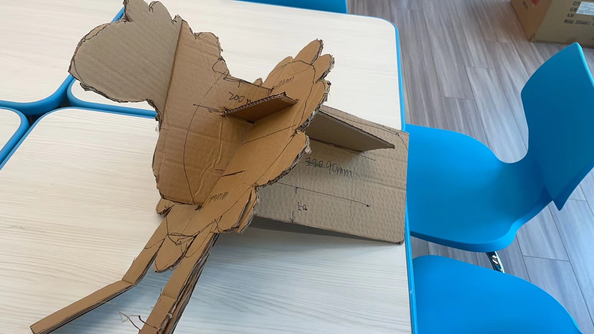
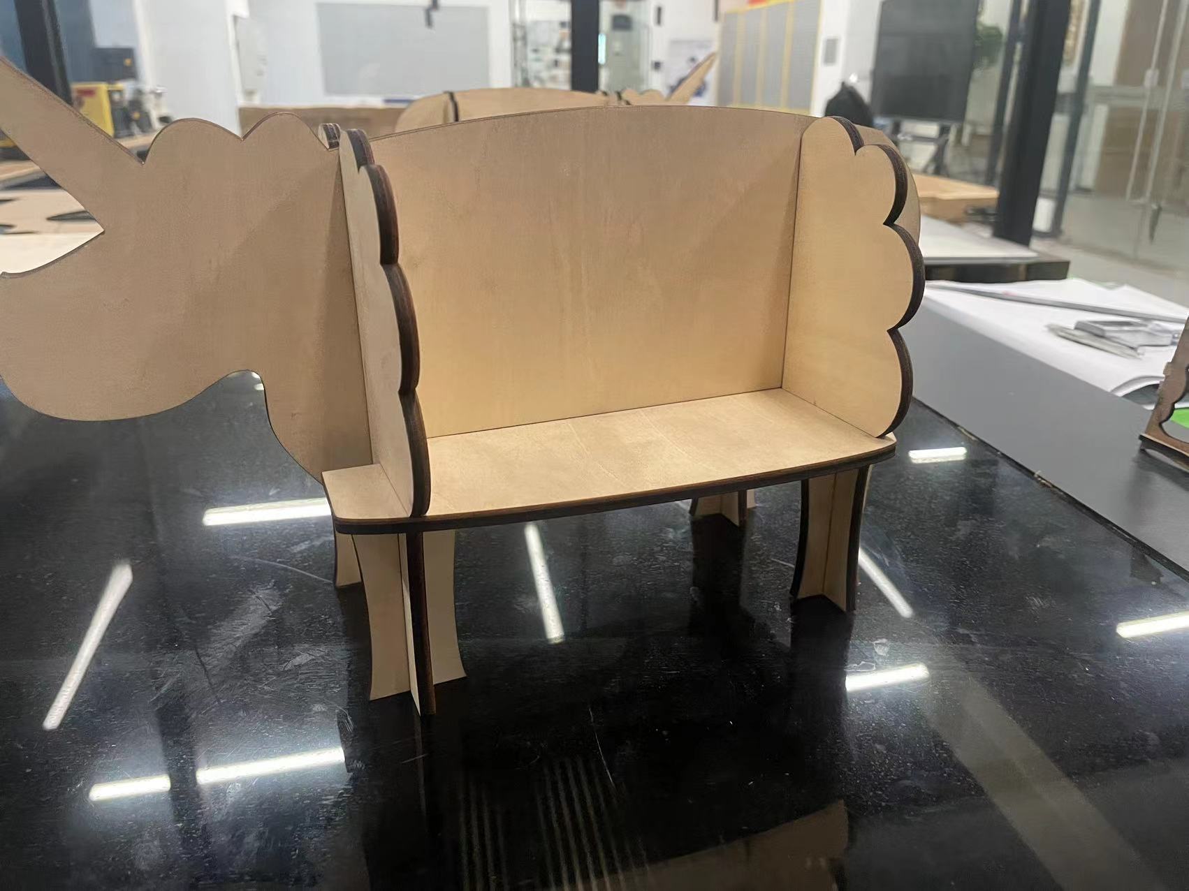
02 I carefully studied this picture, figured out how these wooden pieces were joined together, then conducted a simulation with waste cardboard and determined the dimensions.
The most difficult part are the bottom and finally it turns out it was slided into all the vertical borads.
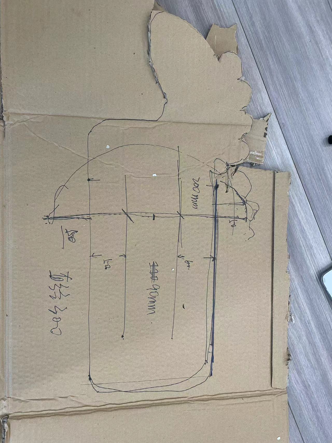
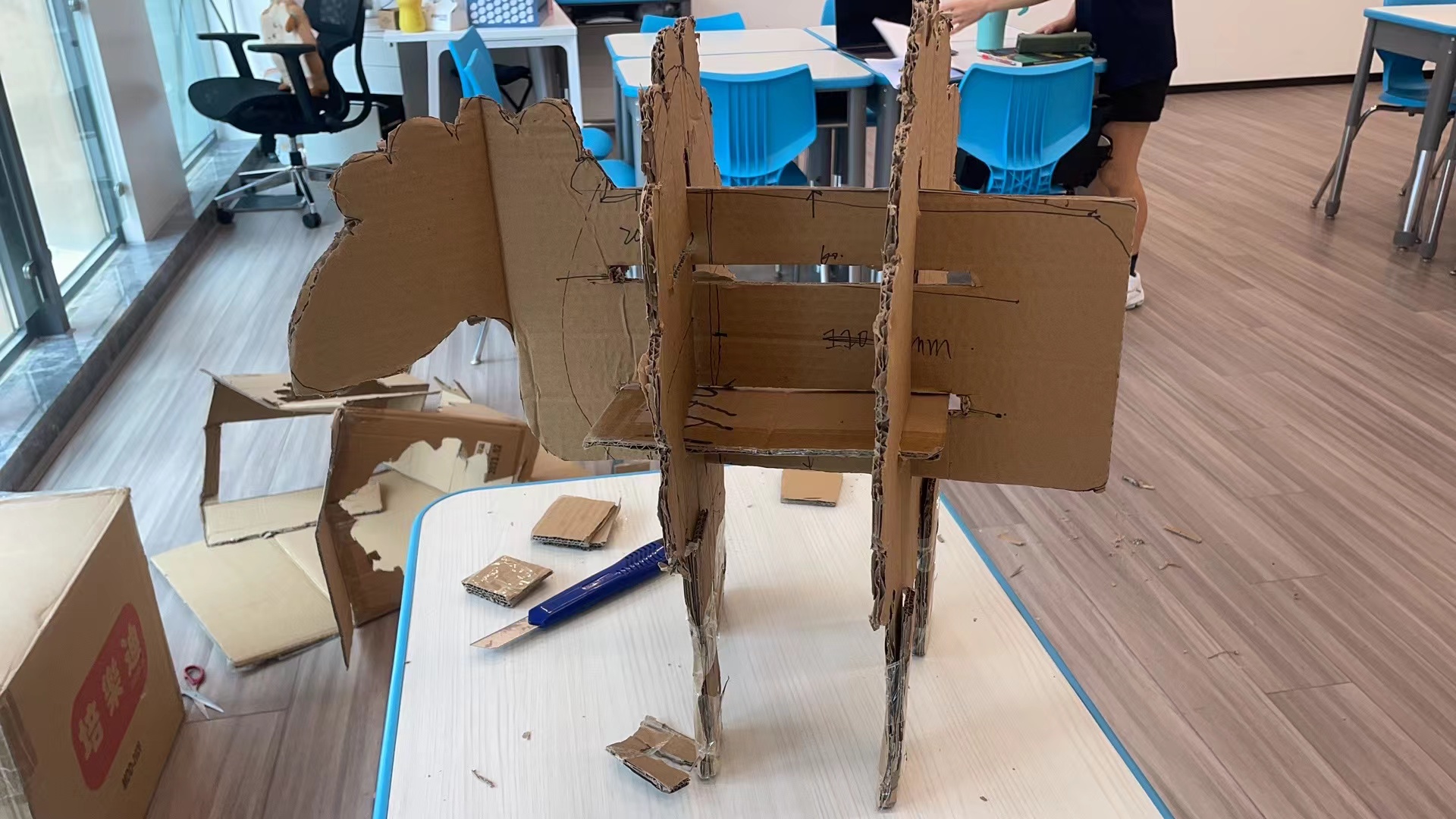
Even it is a totally parper-board sheep, but it stands up!
3D Design using Fusion 360
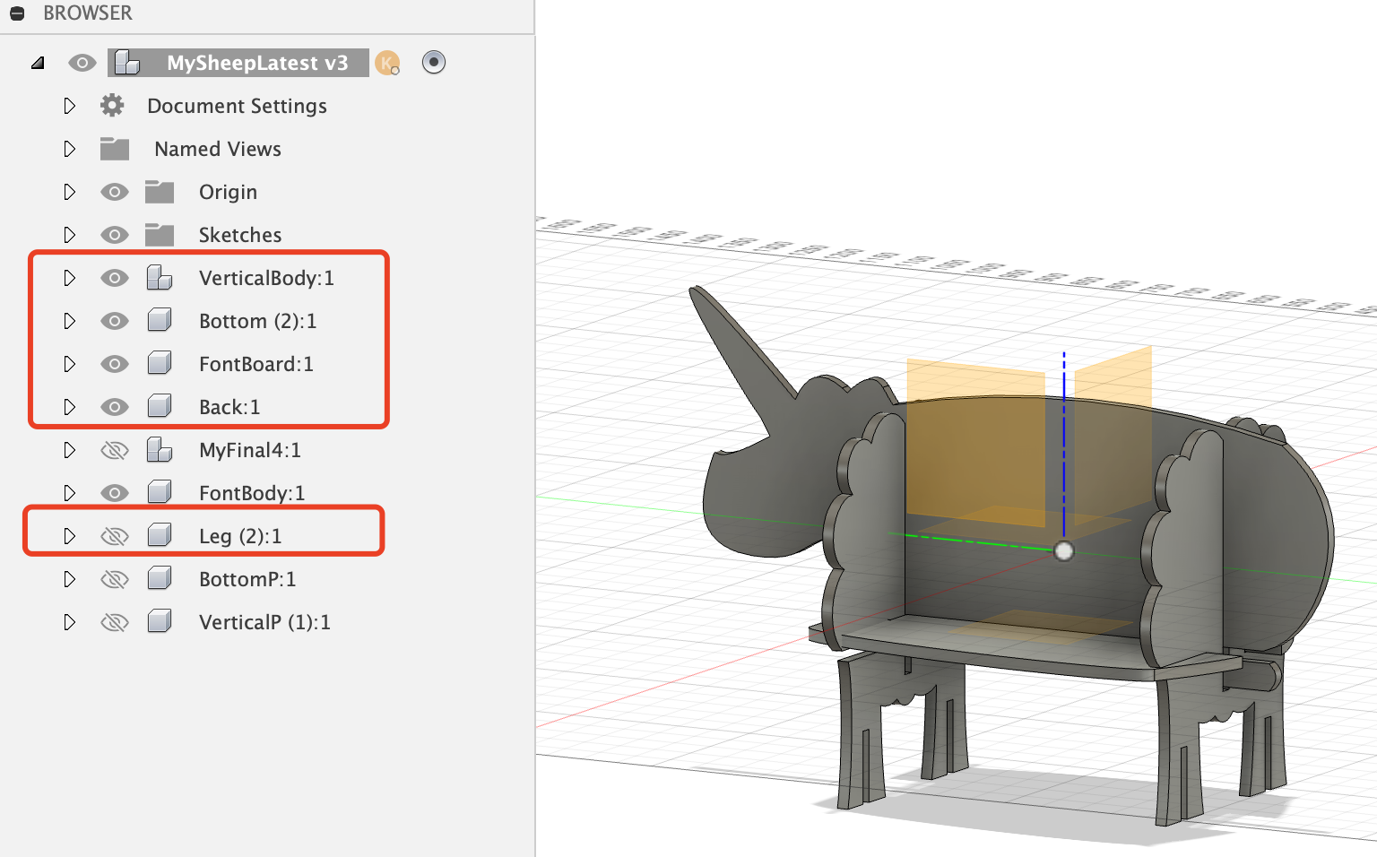
Step 1 Decide Components Division
It will always be the most important step to make a 3D design with multiple parts: Decide how to divide your design into components.
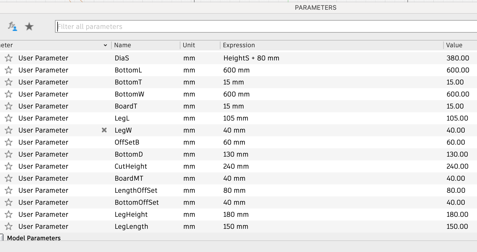
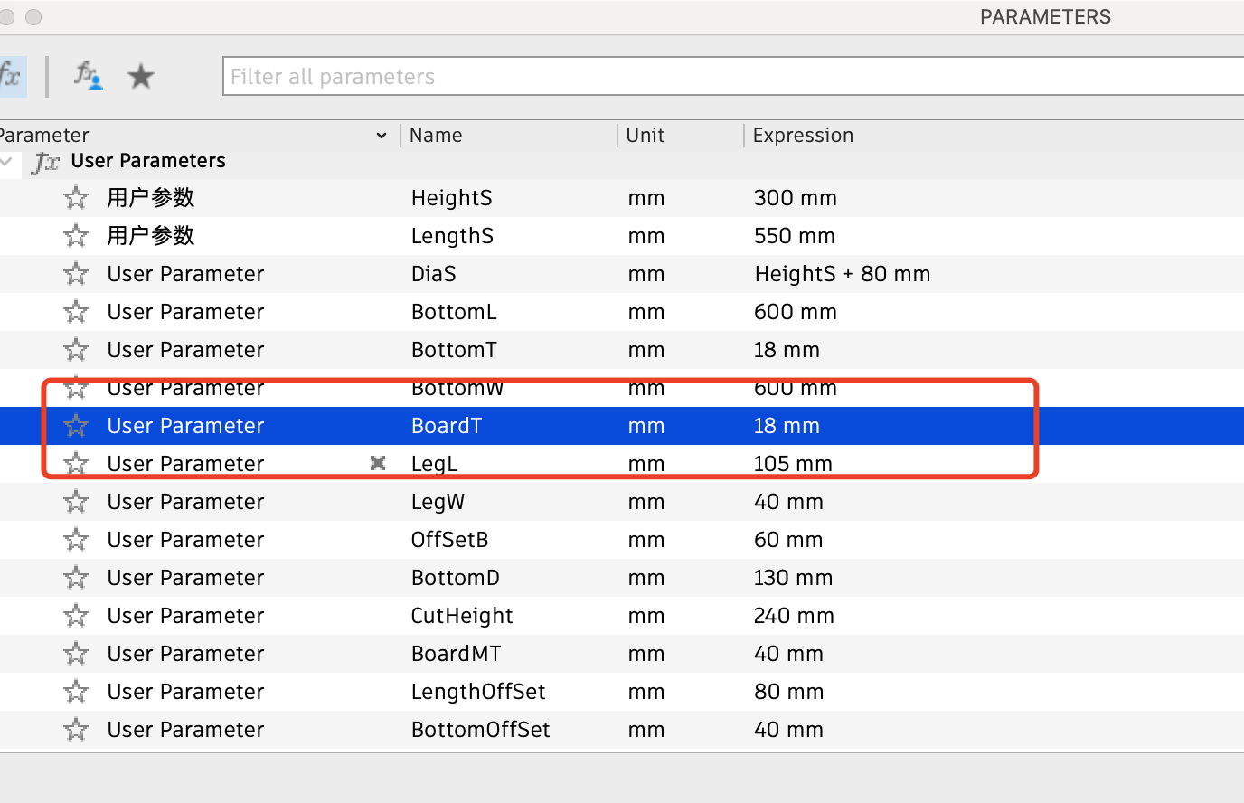
The second most important thing is to design the parameters well.
Step 2 Start from the Vertial Body Part
- The vertial body part will be on the YZ plane to define the base for the whole design, so it is the first component to start.
The second most important thing is to design the parameters well.
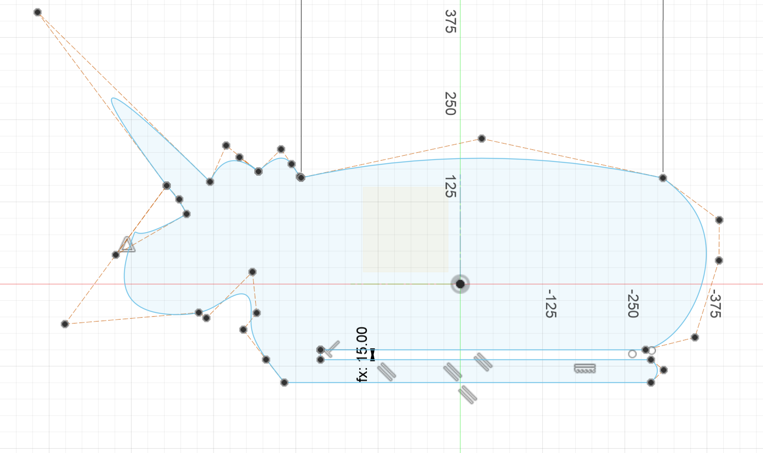
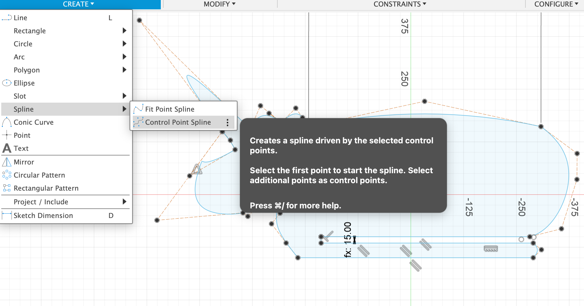
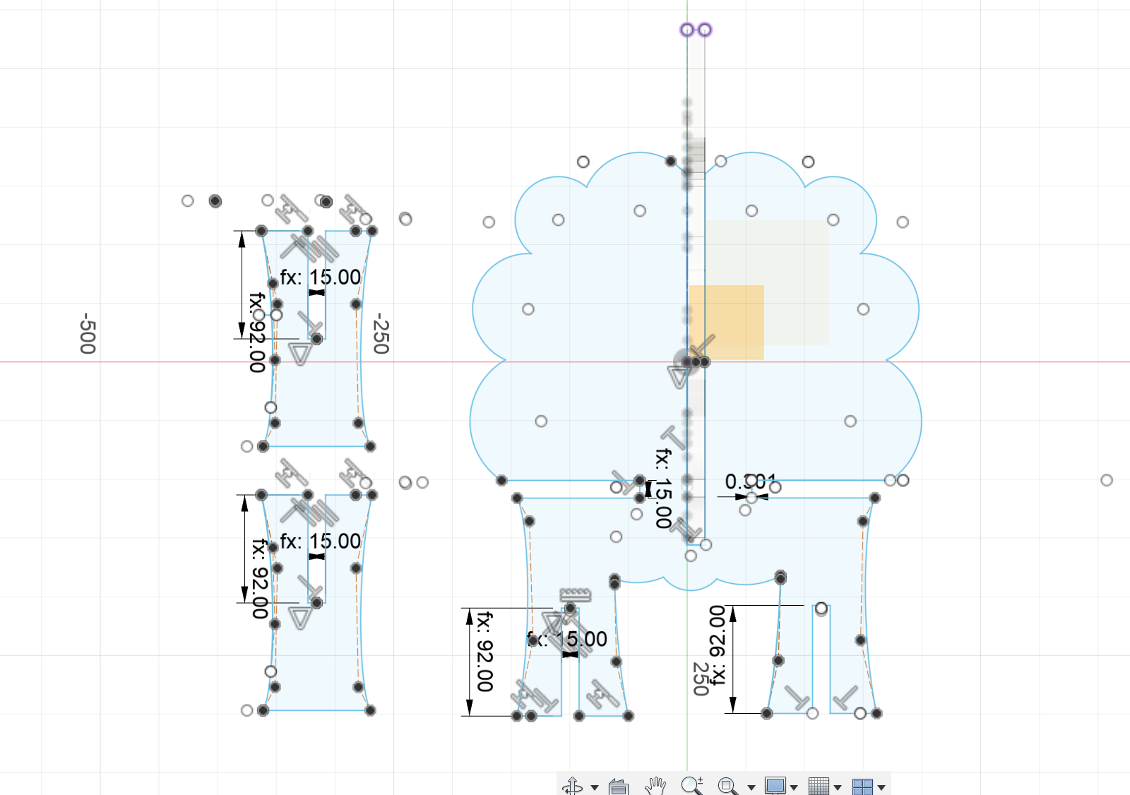
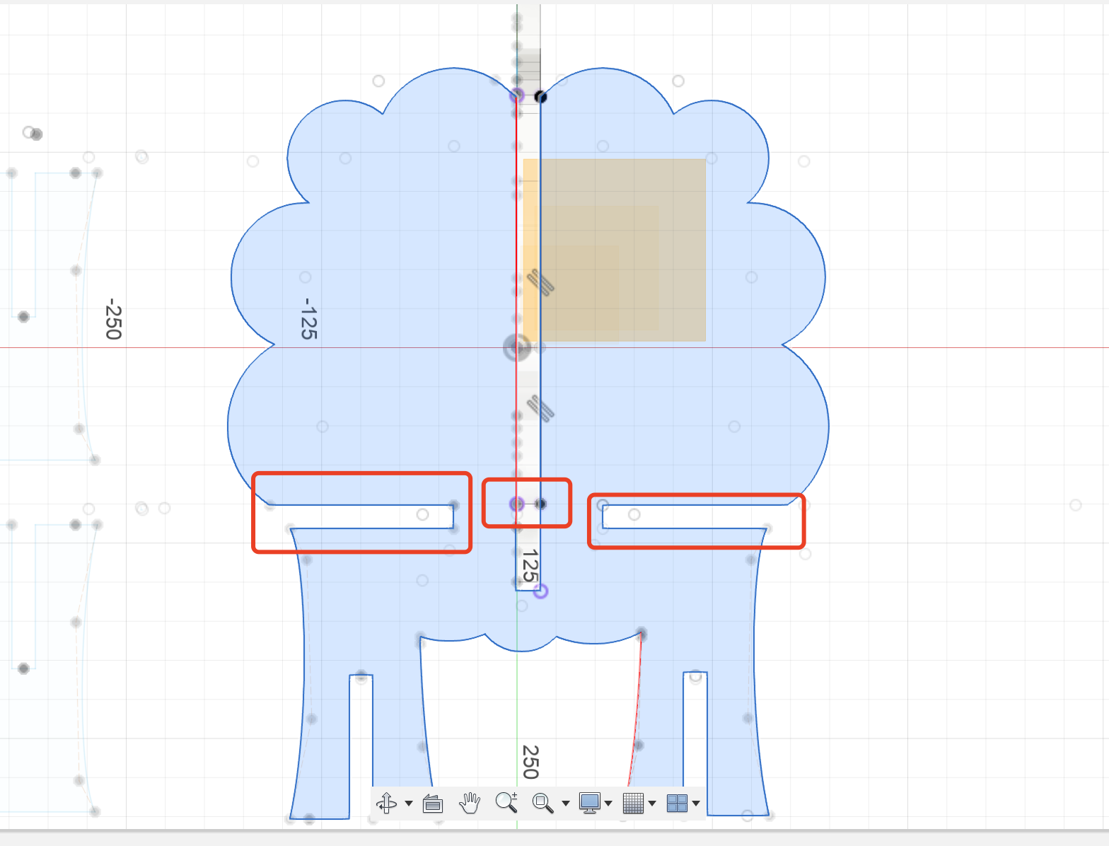
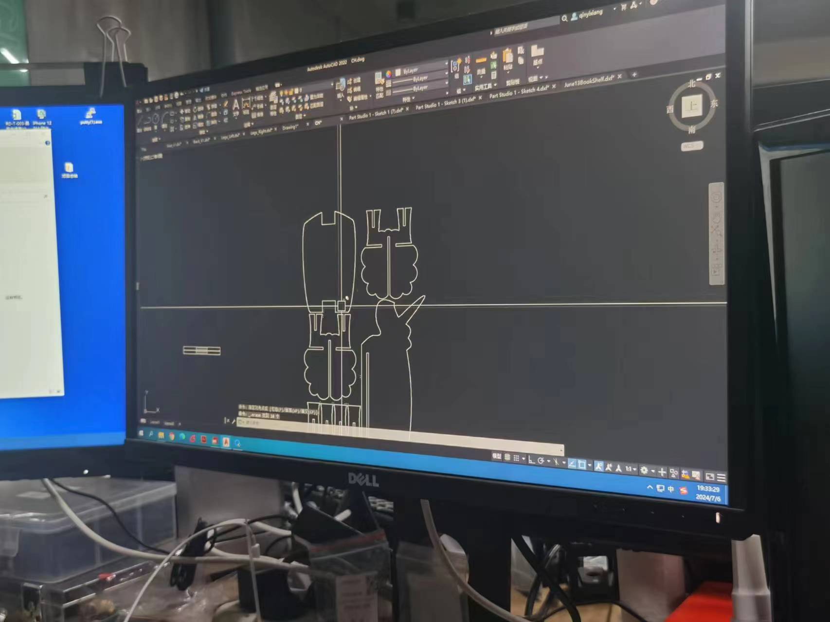
- I drew a rectangle first and drew all the outlines with spine -> Control Point Spline, then deleted the rectangle lines.
Step 3 Second is the Font Body Part
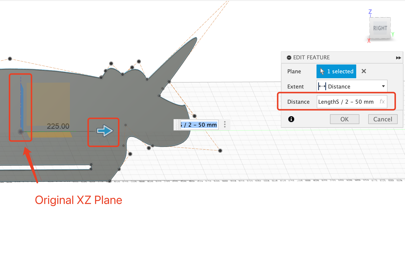
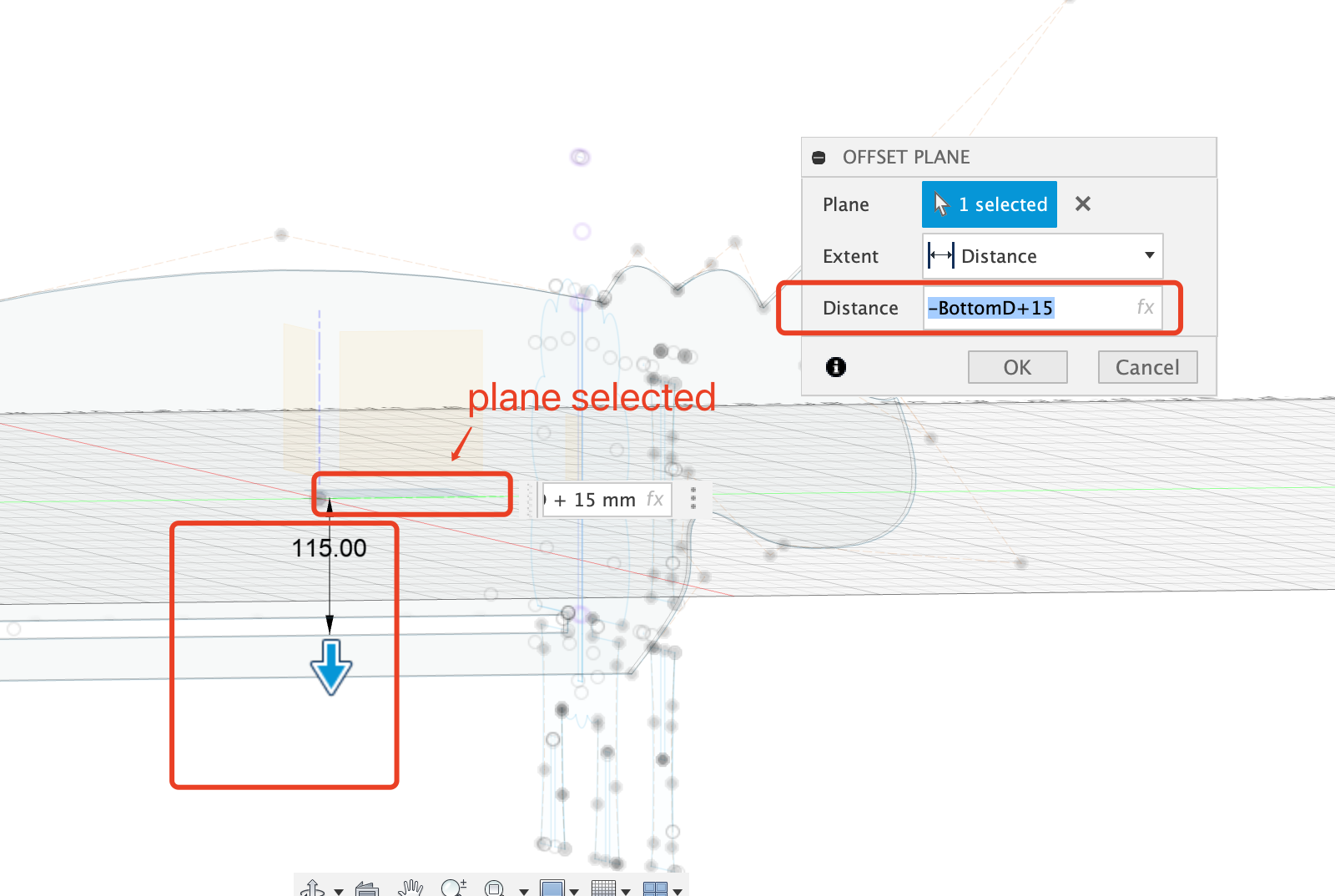
- Decide the offset plane first
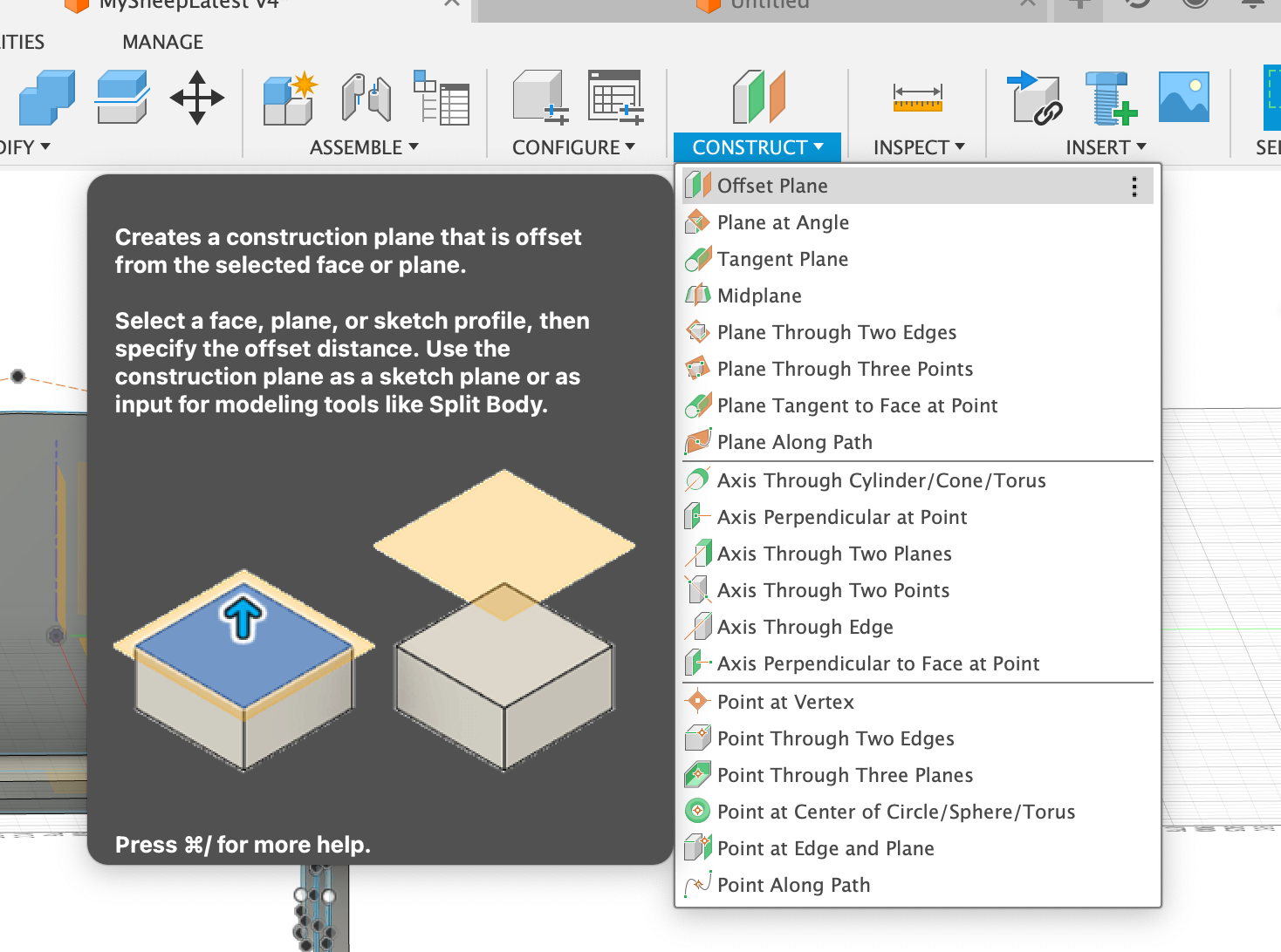
- Define the distance of the offset plane to original plane using parameter
- Start to design the sketch
- Important steps creating this sketch:
- Important steps creating this sketch:
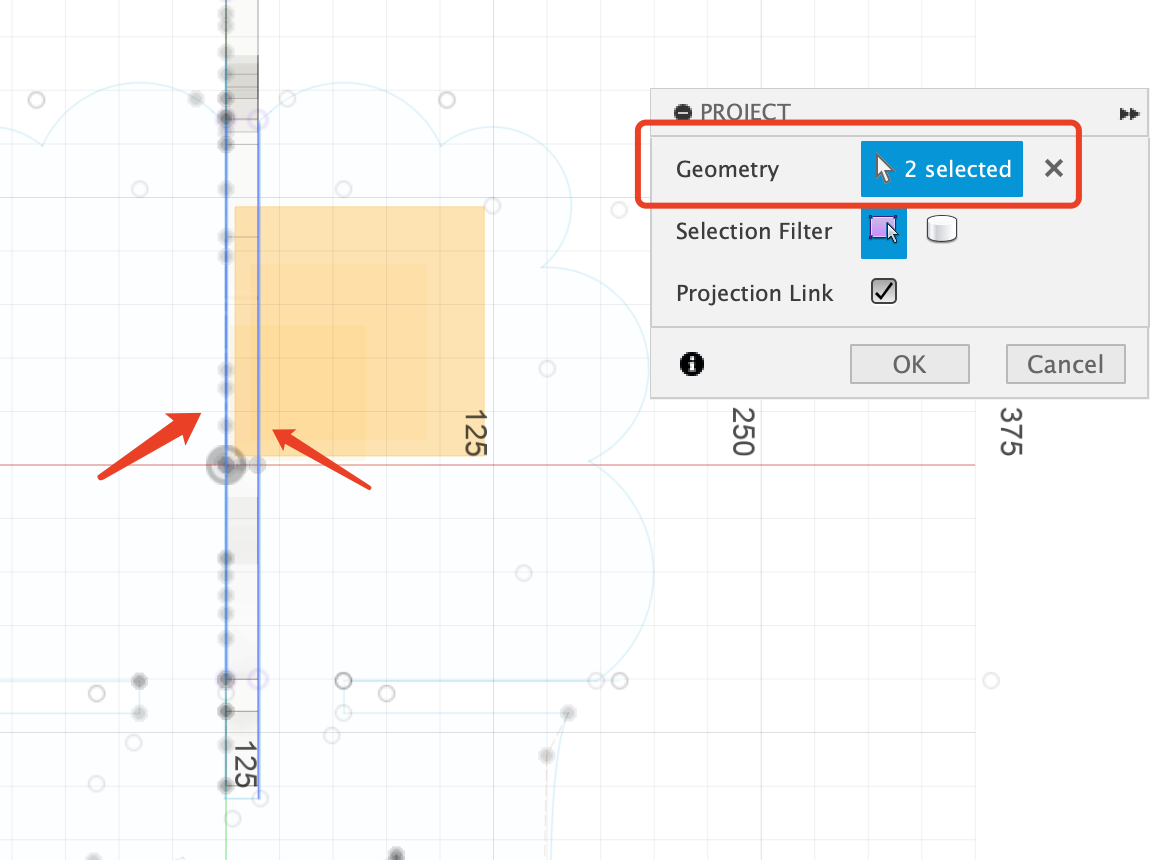
- 1 Project is the vertical body.
Because this part will be intesect with the veritcal body, so it needs to project the vertical body part to find the center position to start.

- 2 Draw Circle and use spine-> Control Point Spline to draw the surrounding petal shapes.
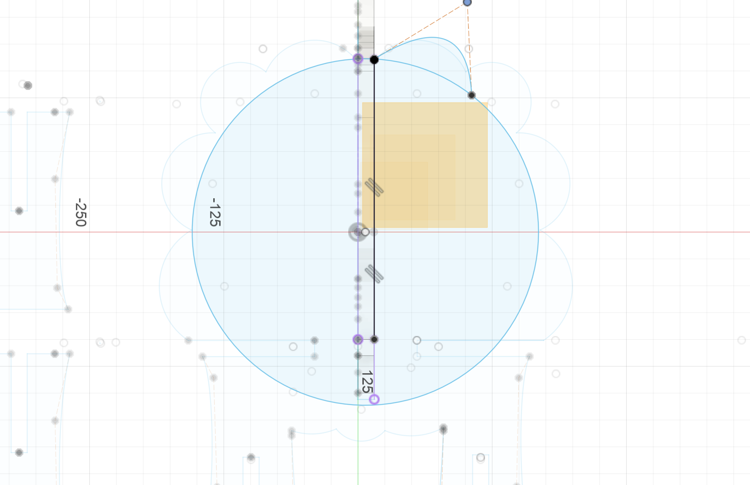
- 3 Make sure the interlocking parts are parallel
- You can use the dot projected to decide the parallel starting point
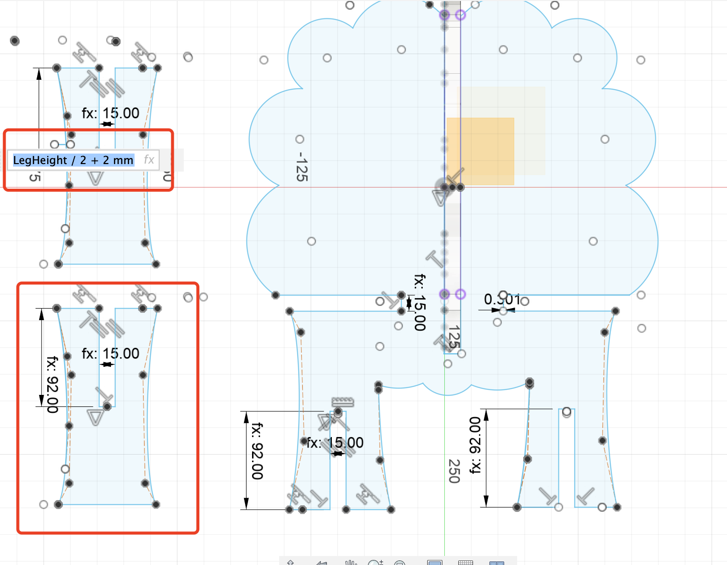
- For the rest of the legs, mostly I used the spine -> Control Point Spline again
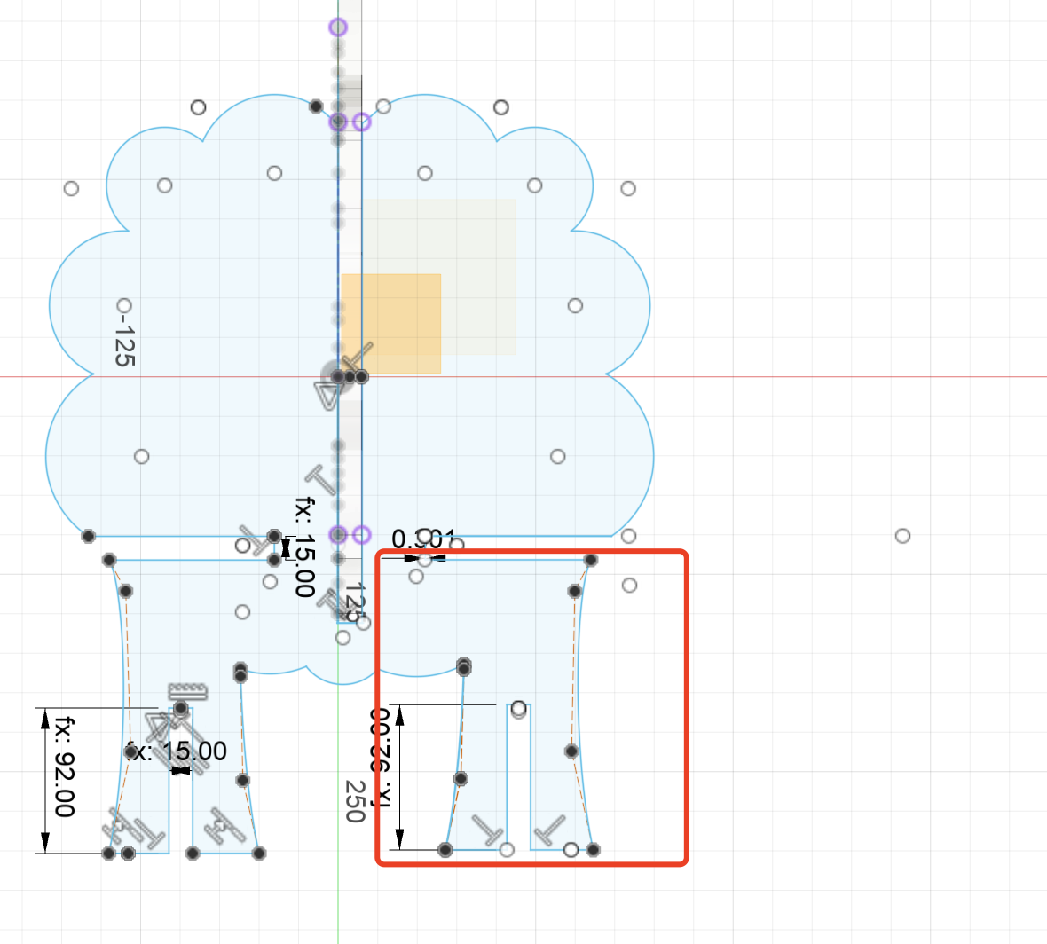
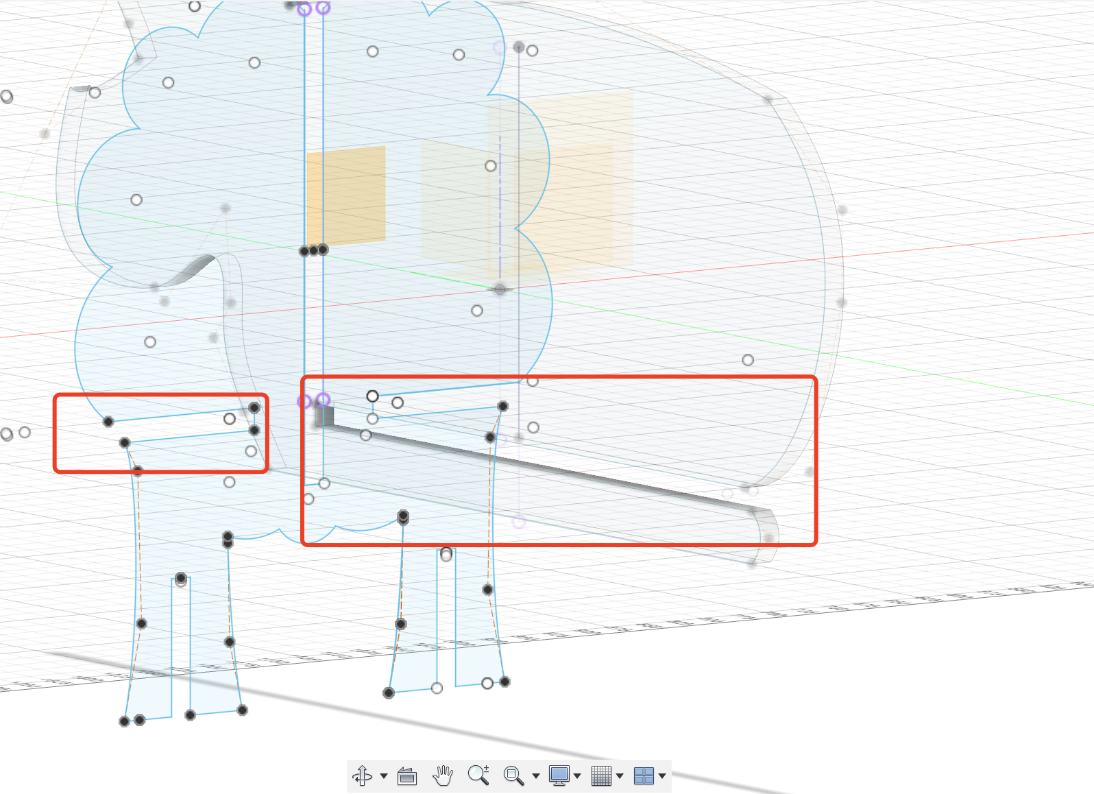
- The other two calves that need to be interlocked with the legs on the body. Just pay attention to the setting of the parameters.
Step 3 The Back Body Part
- This part needs to set up the offset plane correctly and then just simple copy the body of the font part.
Step 4 The Bottom Part
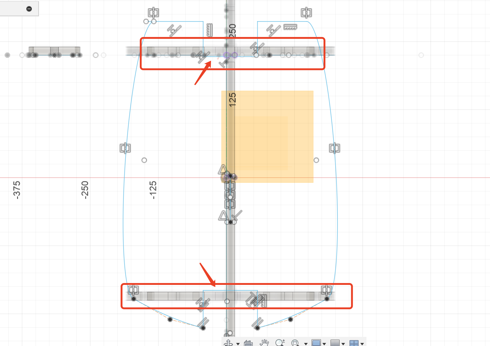
- The bottom needs to intersect with the all the other parts, so the offset plane setting is very important.
- Calculate the offset value of the plane, it needs to be exactly the gap position of the vertical body part.
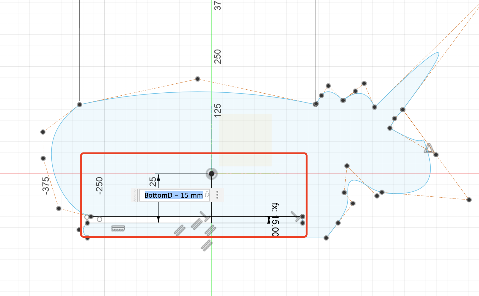
- Construct the offset plane.
- Sketch.
The sketch of this part is very easy,needs to project the two body part, because It is necessary to determine that the bottom plate and the two vertical body parts exactly avoid creating sufficient notches for interlocking.
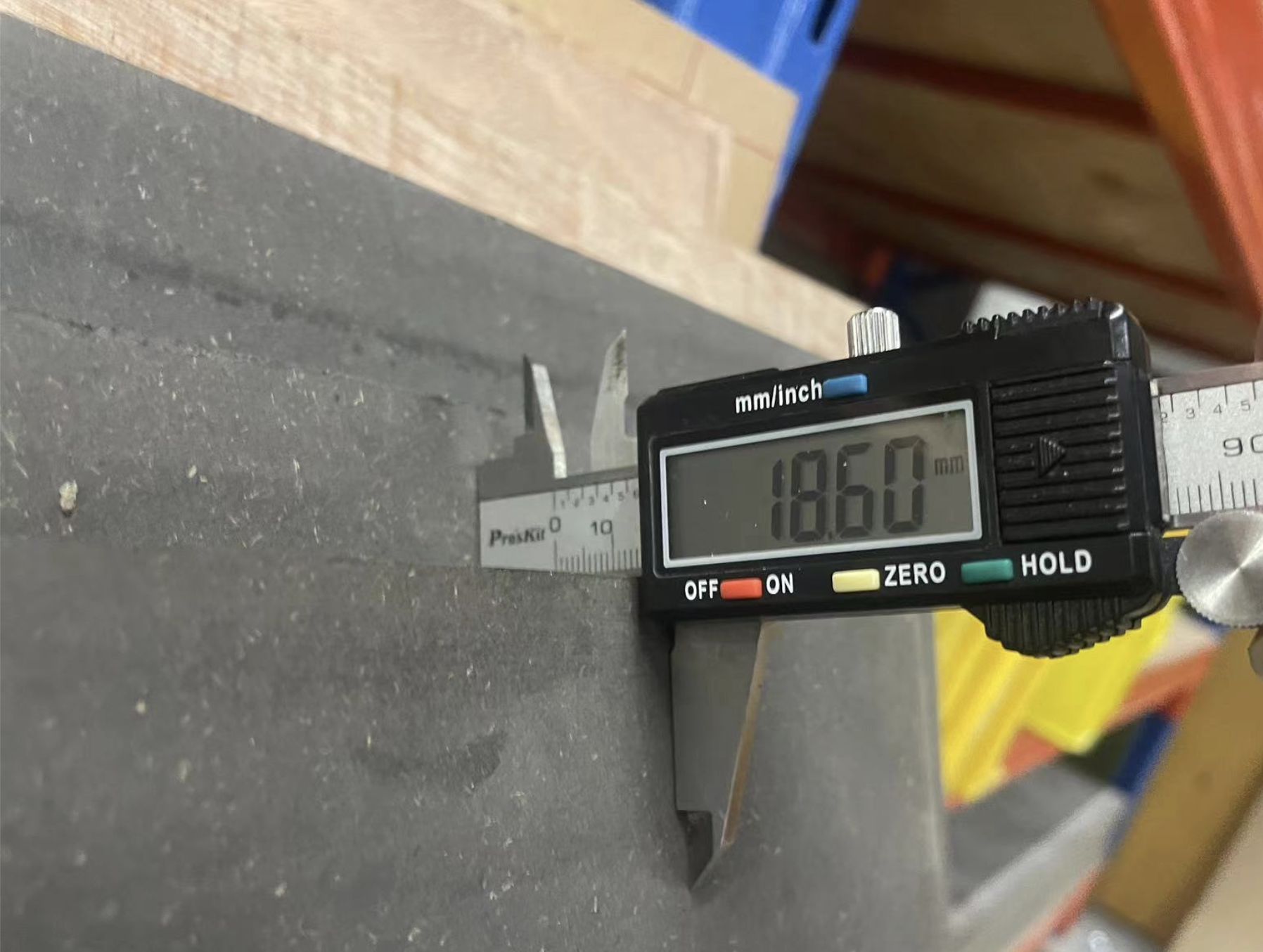
Change the parameter
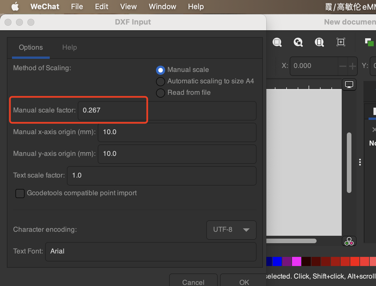
Firstly, I set the gap for the parts of the board that need to be inserted and assembled to 15mm. Later, after measuring the thickness of the board at 18.60mm and consulting the master about the approximate kerf, I set this value to 18mm.
Laser Cut
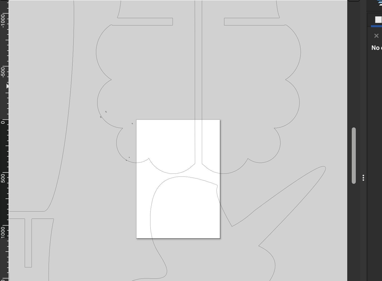
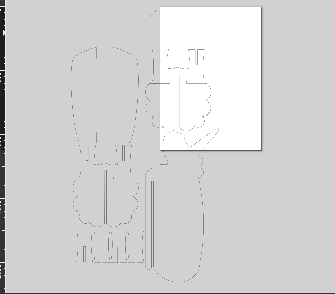
Laser cut the pieces and assemble the sample
BIG CNC CUT
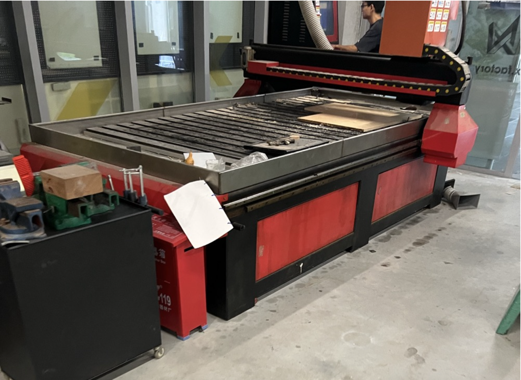
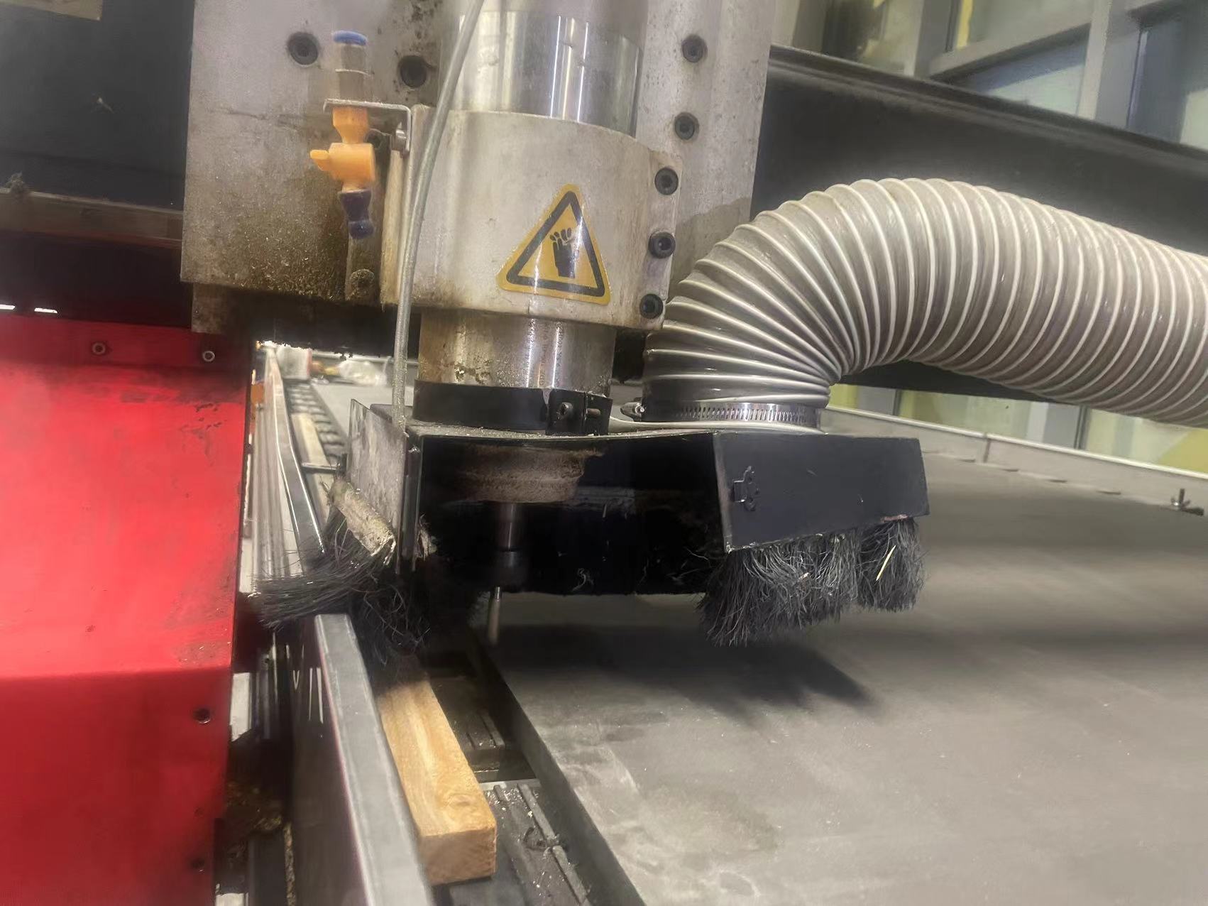
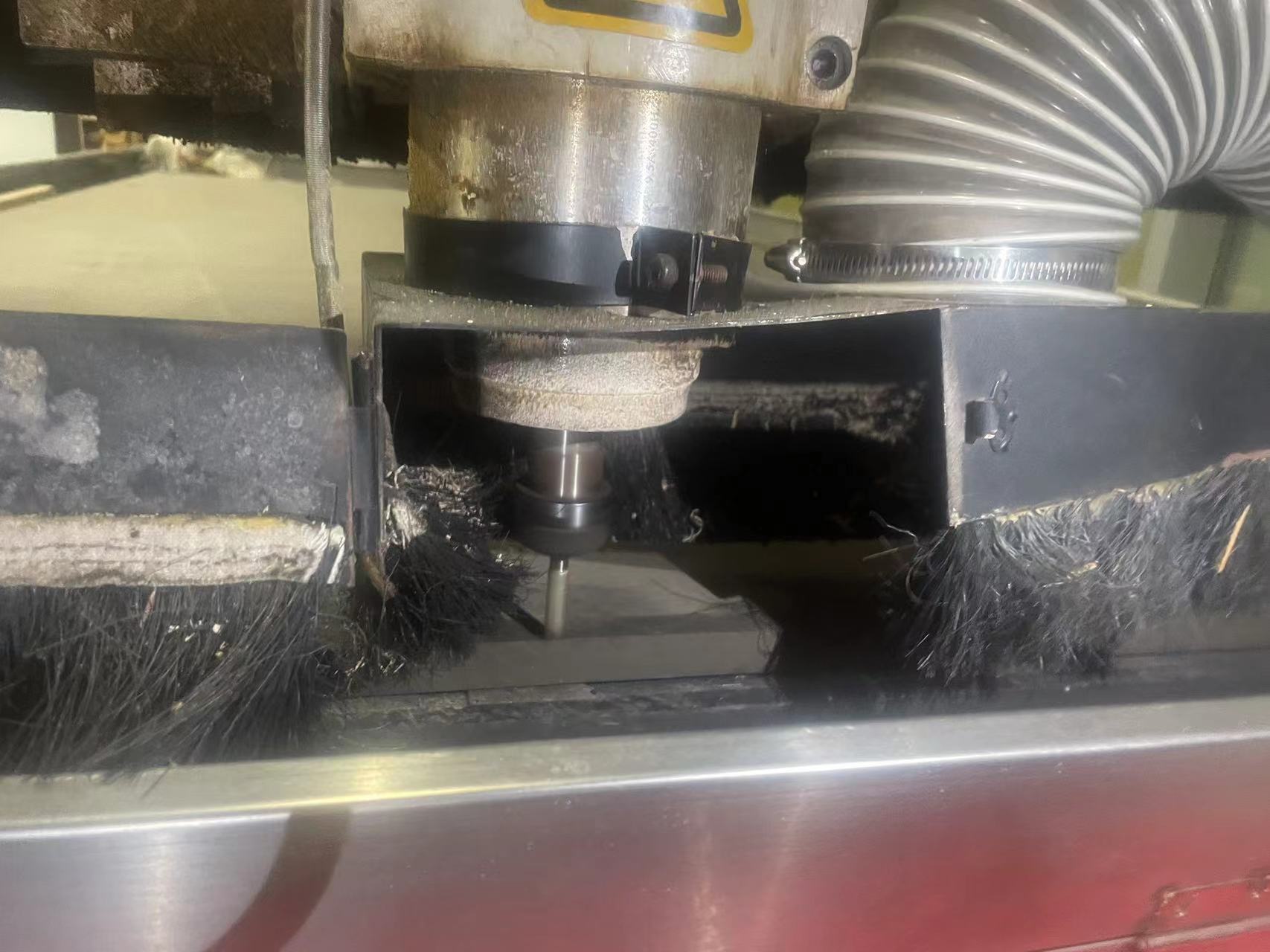
1. Our big CNC machine
2. Export the step file and the master who taught us CNC combined all the furniture designs of everyone using software.
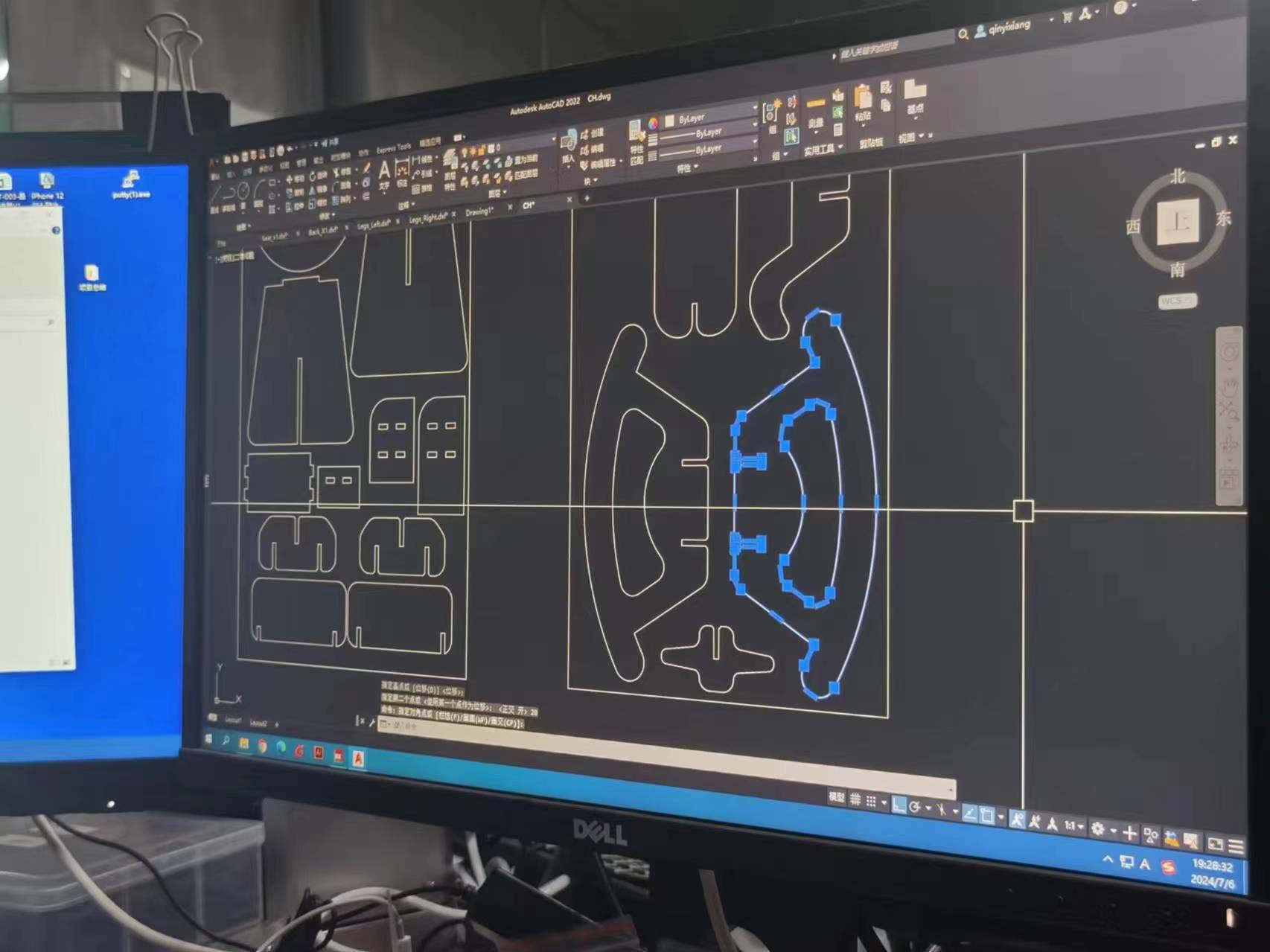
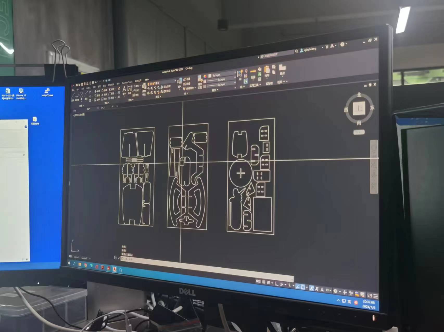
3 Generate the toolPath.
4. The Gcode is ready,now we are going to cut.
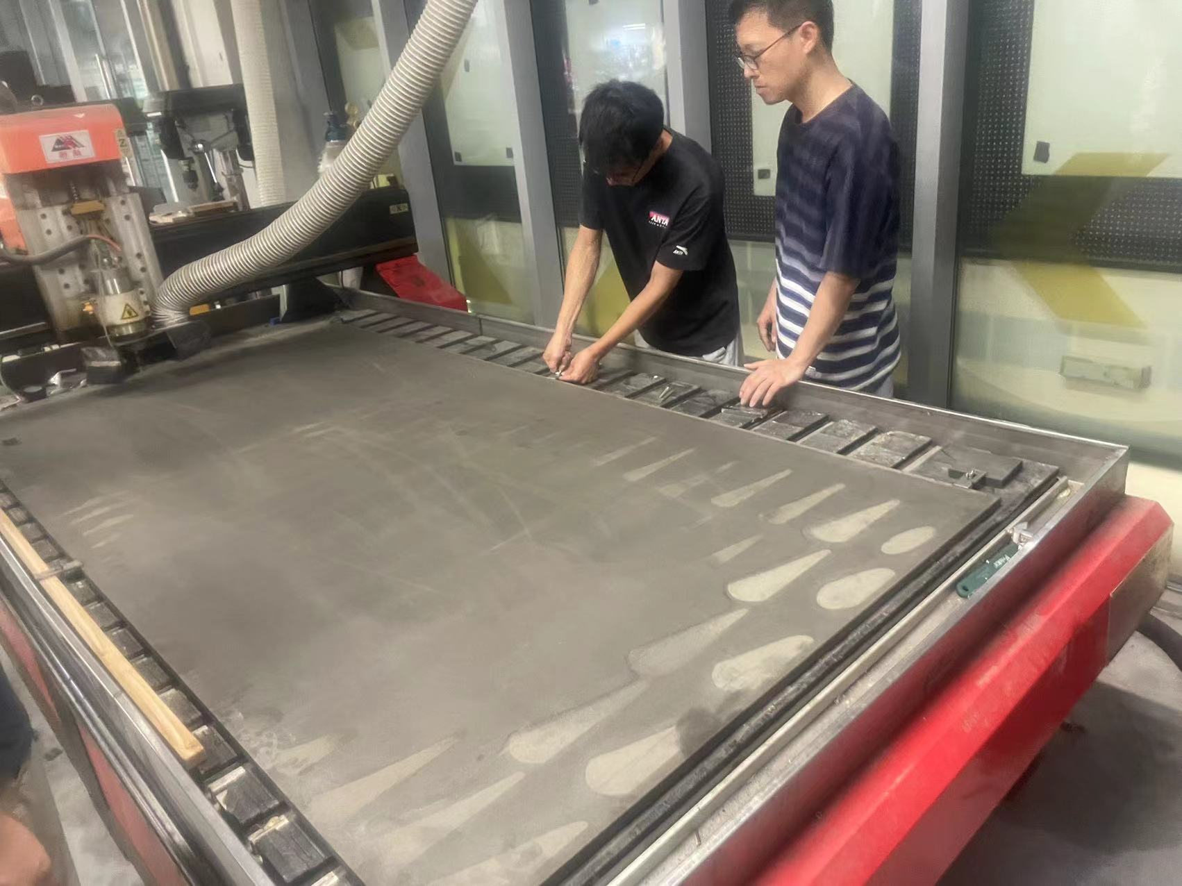
4.1 Fix the board on the machine tightly, it needs to be fixed very tight otherwise the board may shift positions.
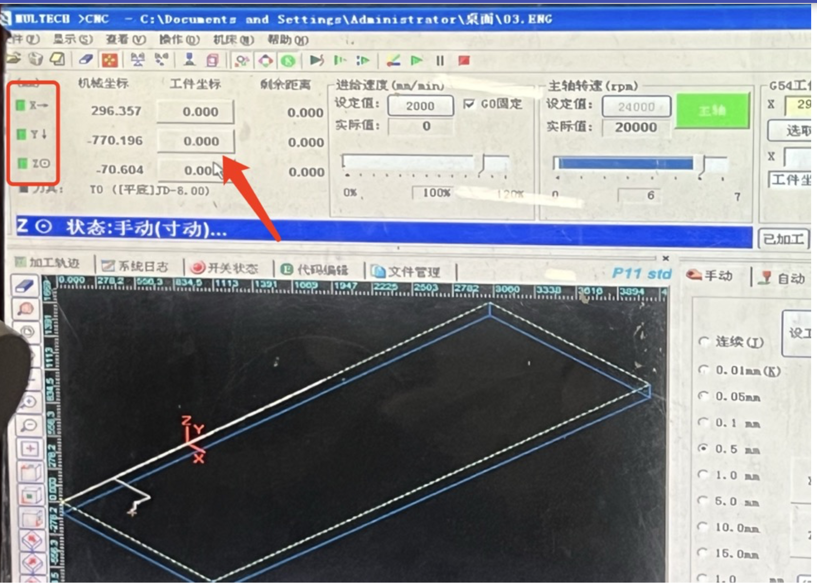
4.2 Adjust the X and Y orgin
4.3 XYZ origins all set
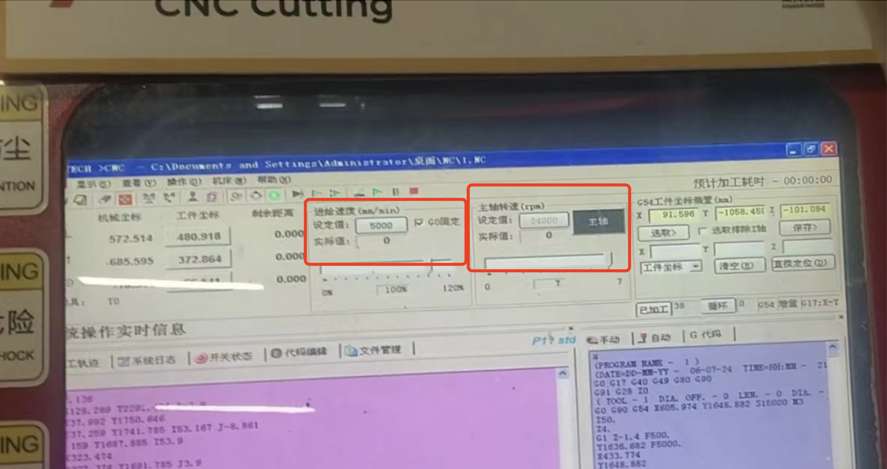
4.4 Set the feed rate to be 5000 mm/min and the spindle speed to 24000 rpm
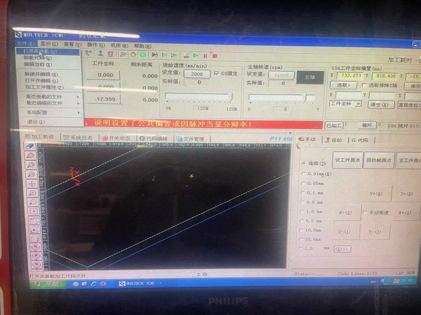
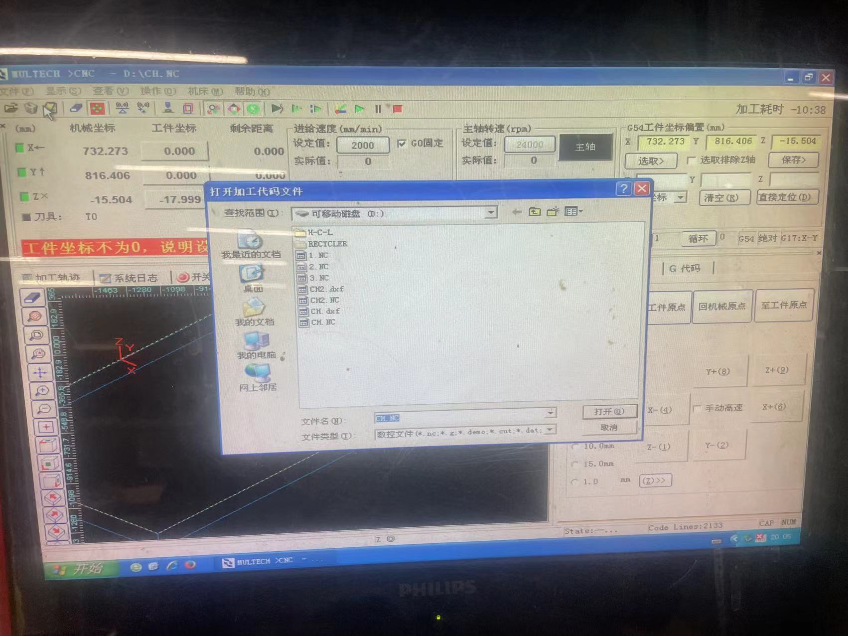
5. Load the Gcode file
6. Press F8 to make the simulation path
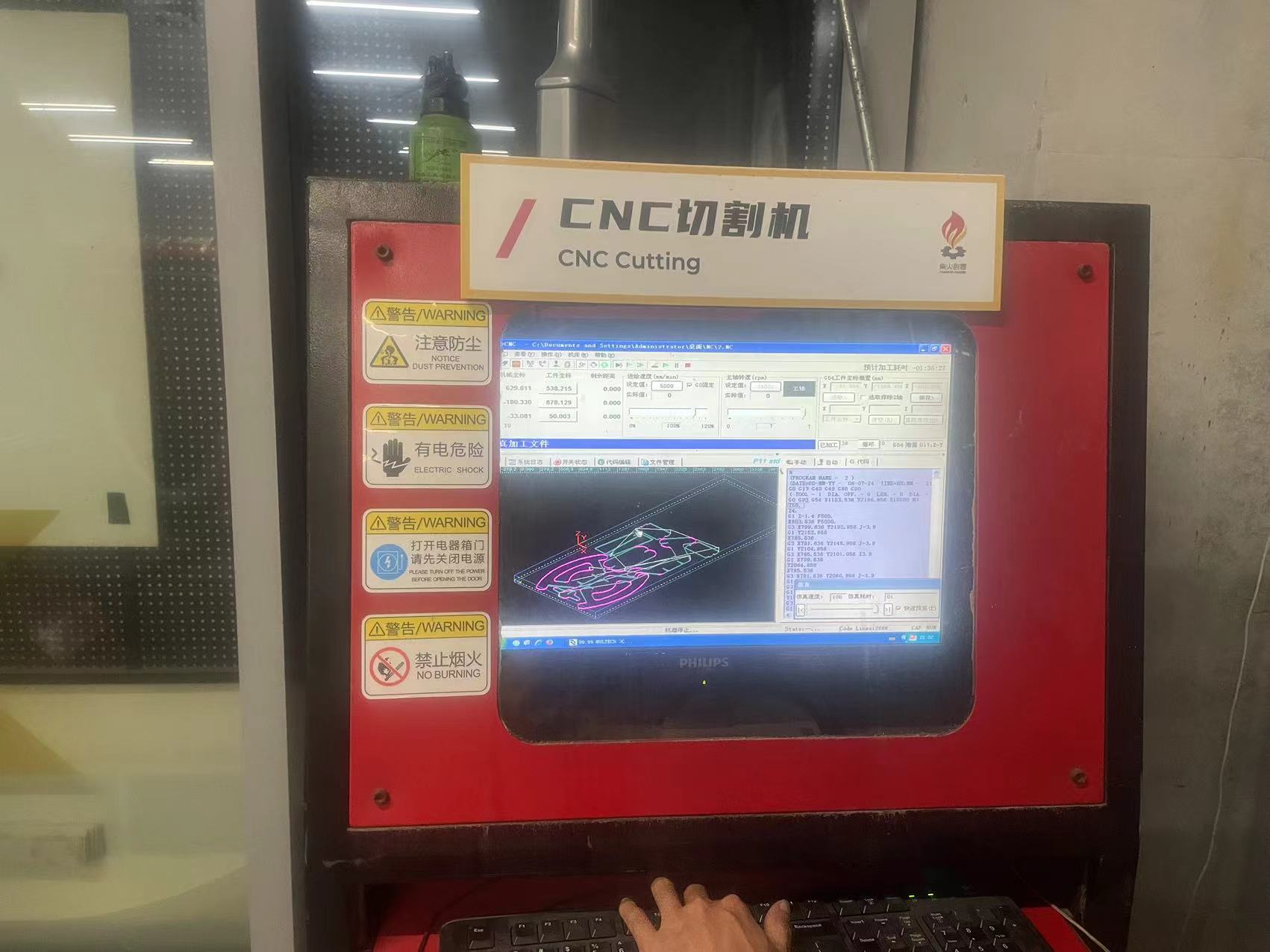
7. Press F9 to cut!
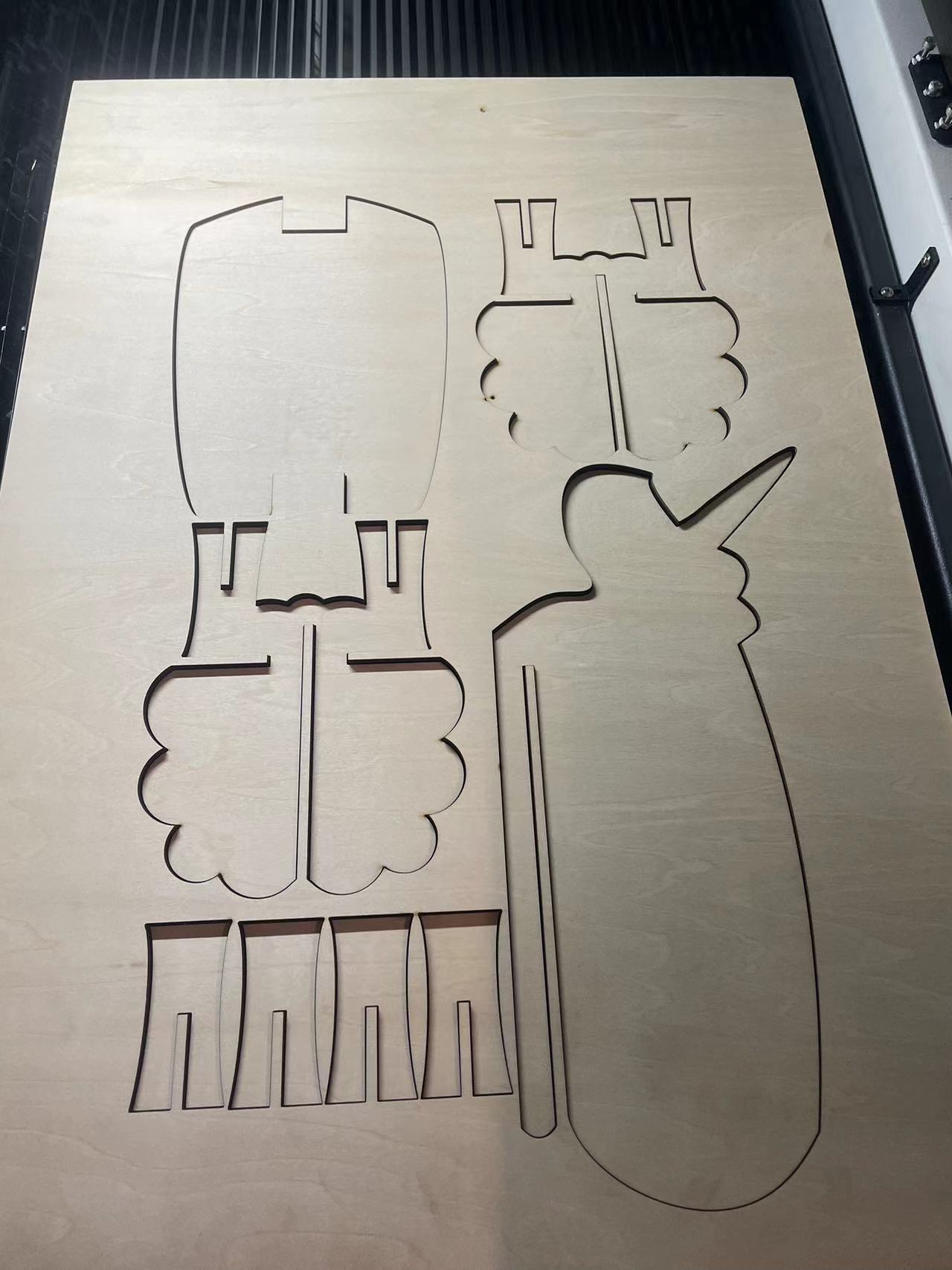
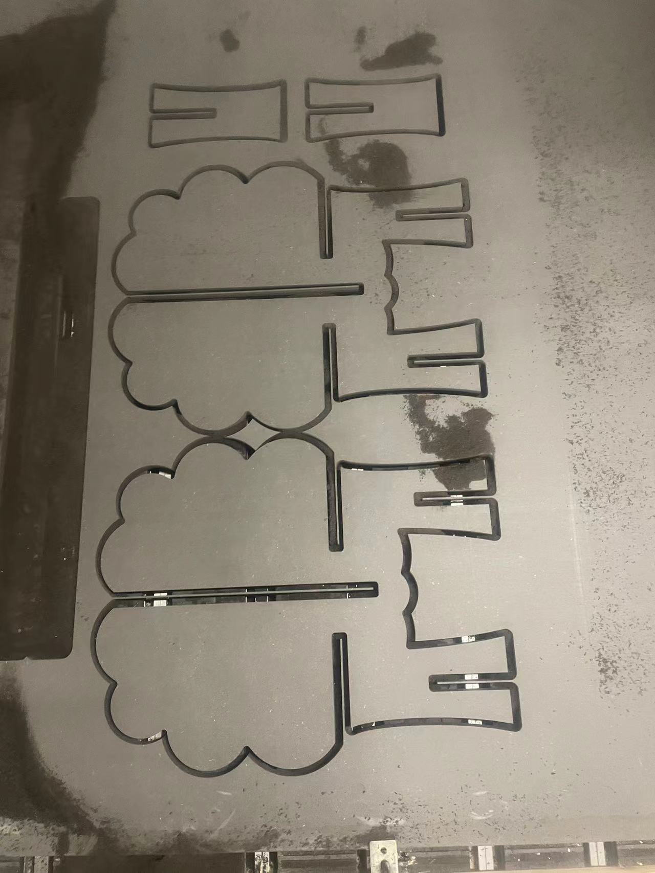
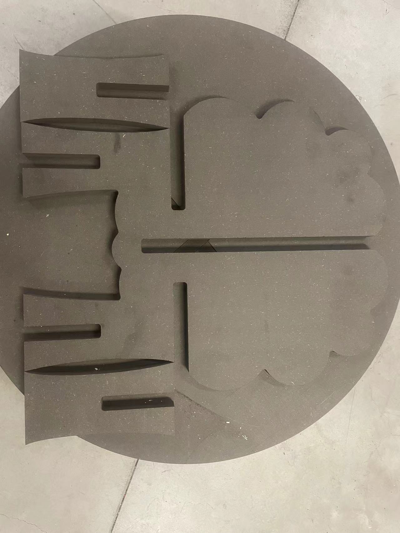
8. Our First board!
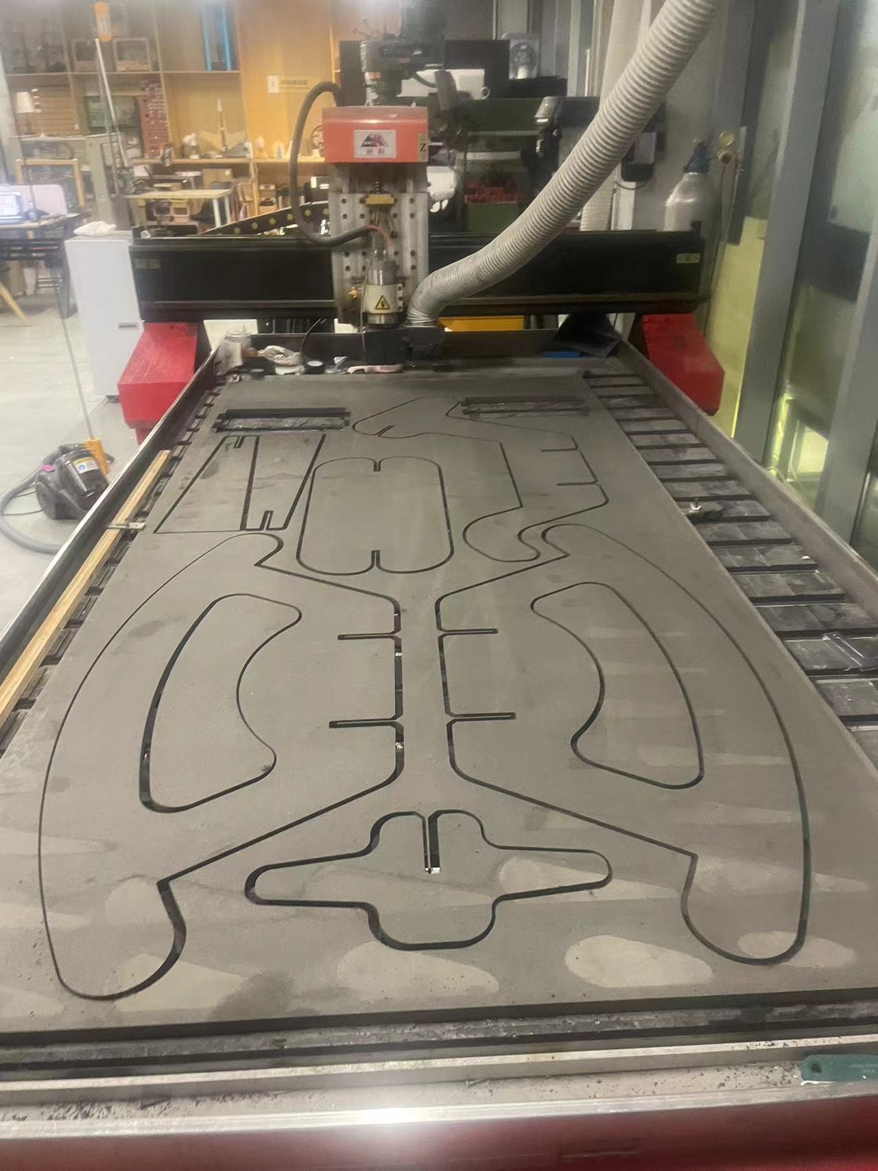
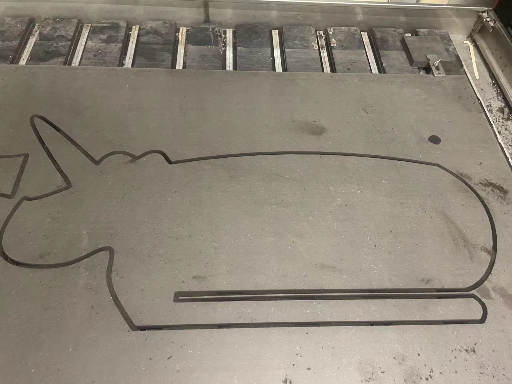
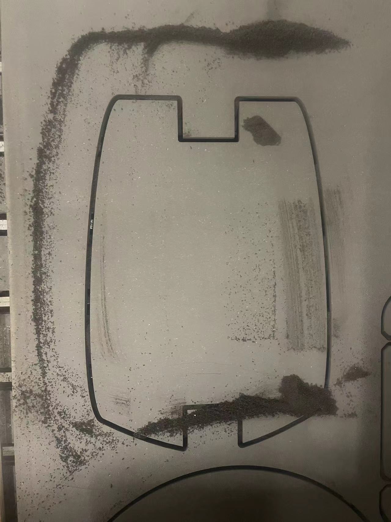
. My part is cutting
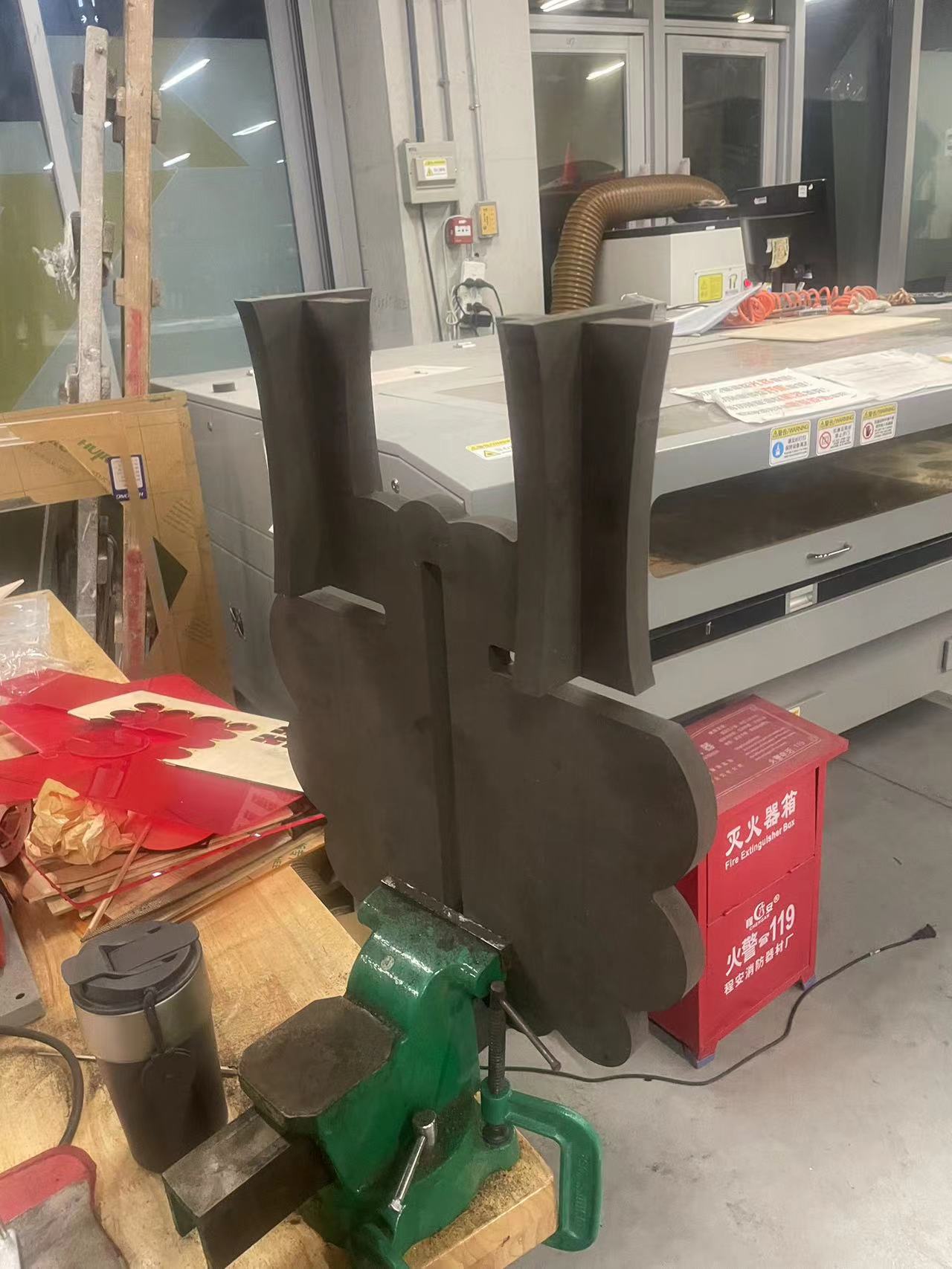
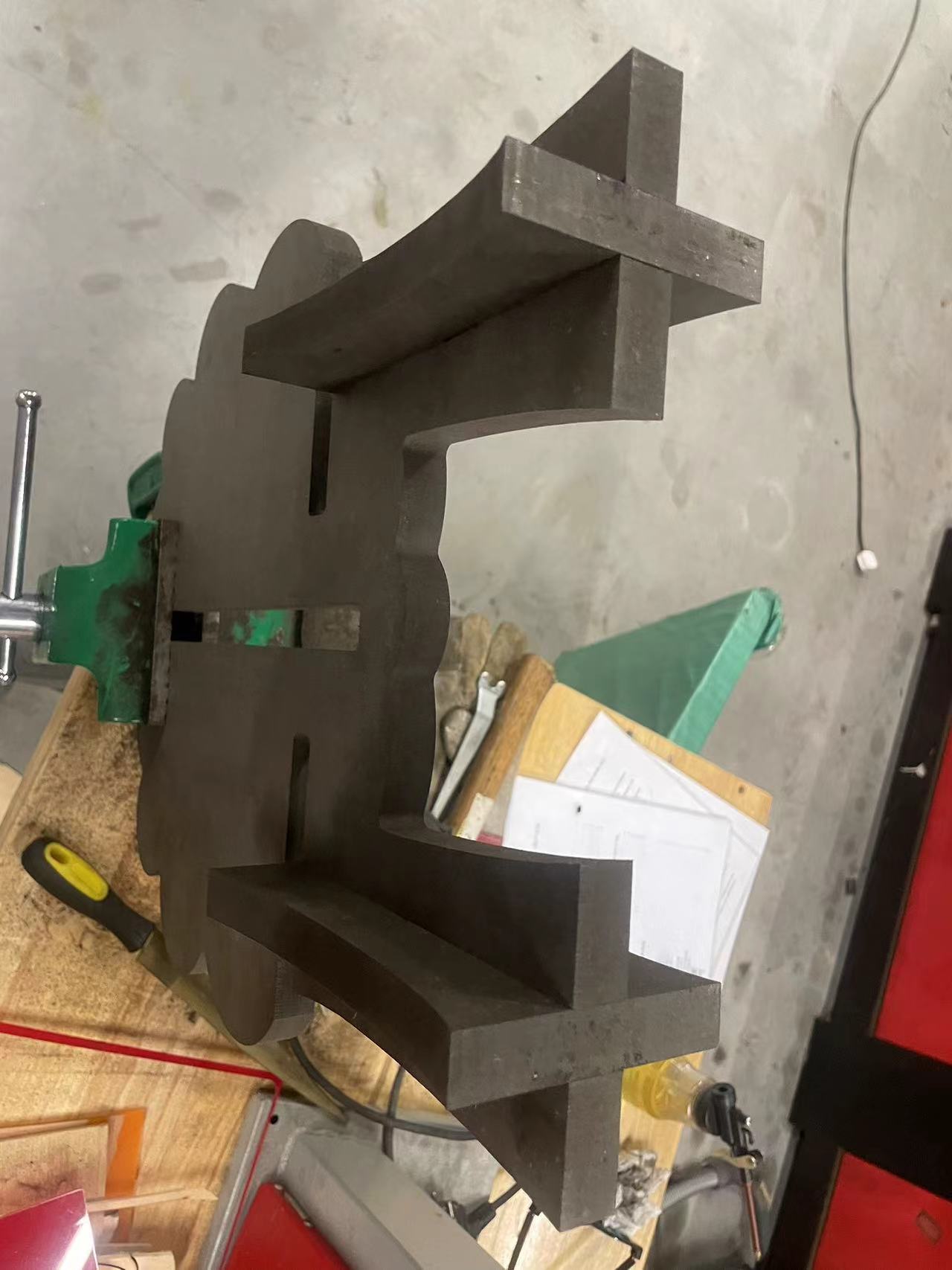
Assemble
Part 1 Legs
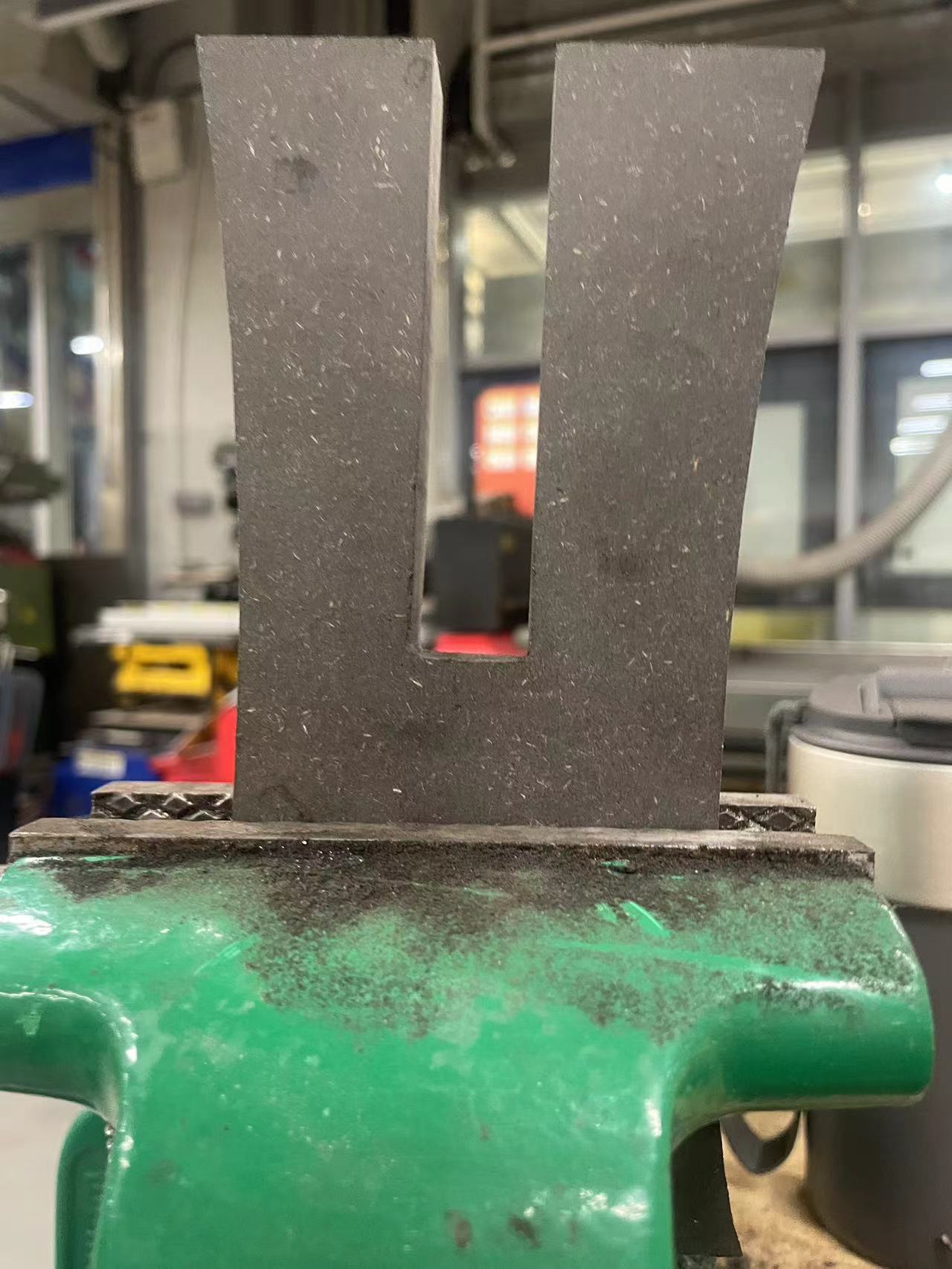
When I tried to install the legs, the original size was supposed to fit perfectly.
So after piecing it together, the legs were not flat.
The reason is that the machine cannot cut right angles during the cutting process but can only cut at angled arcs.
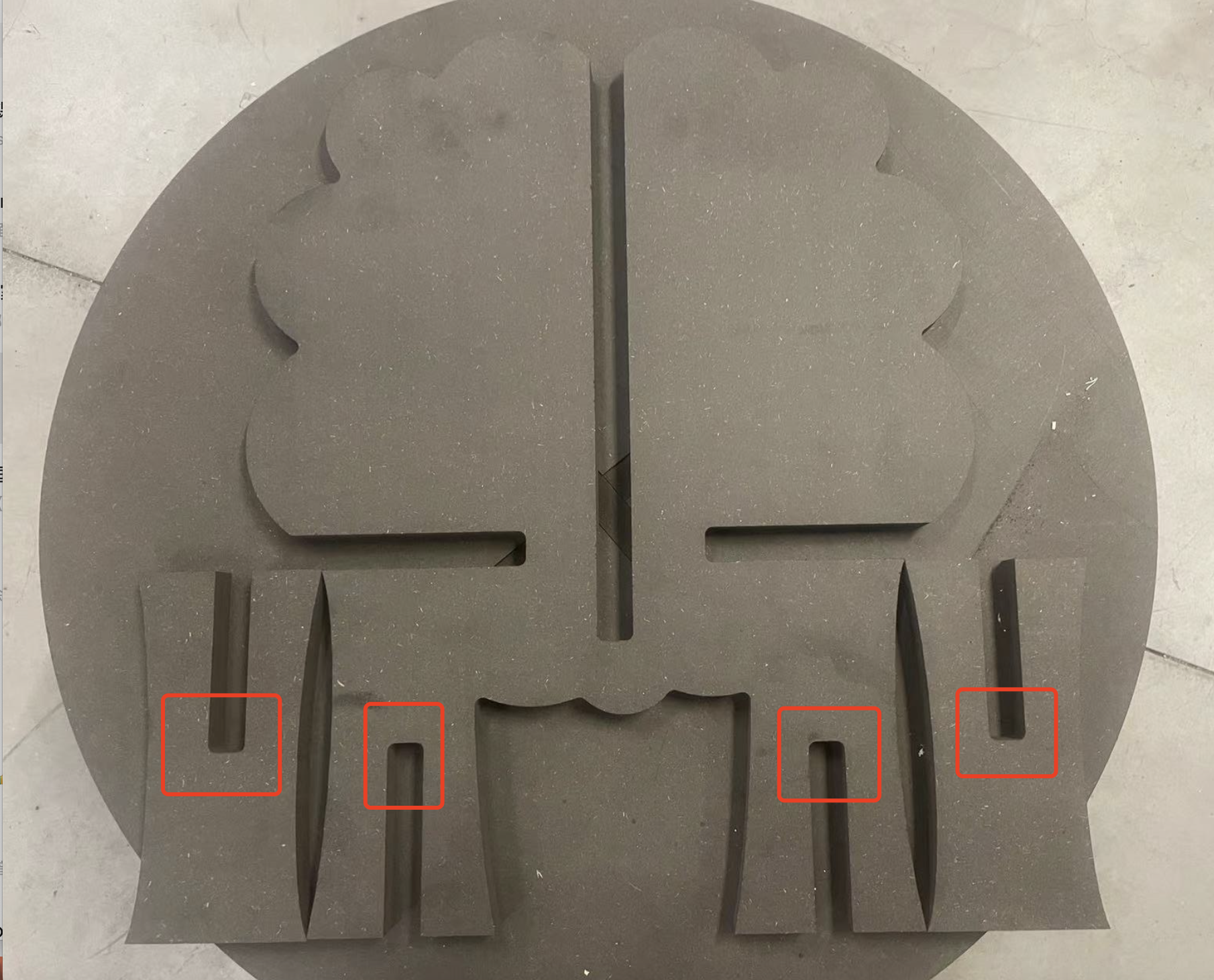
So I decided to use a file to file the angled arcs into right angles
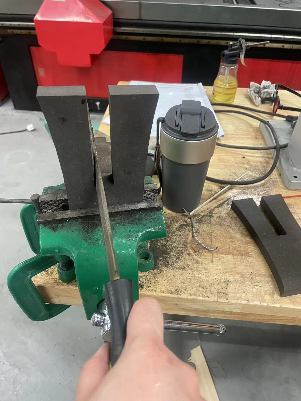
After few minutes,got the right angles
Now the legs can be perfectly fit.
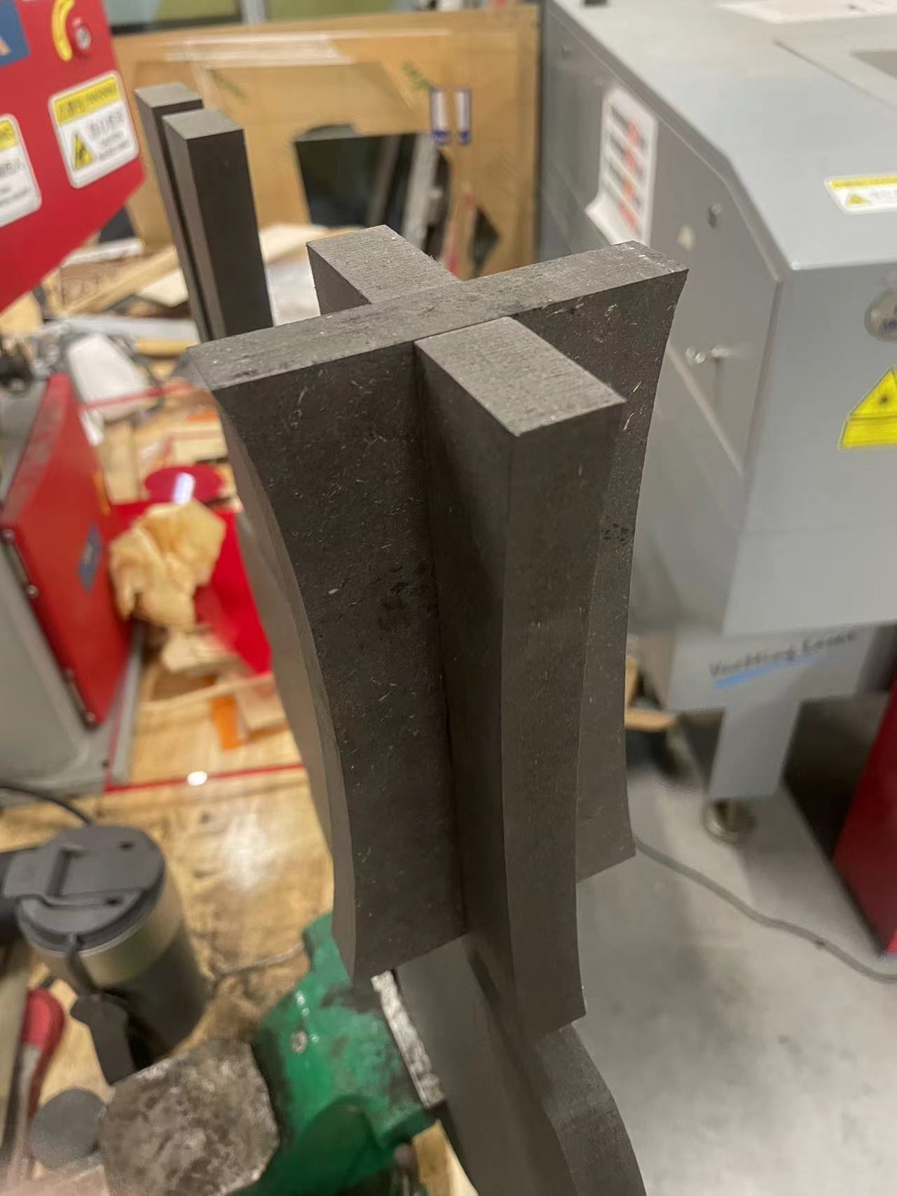
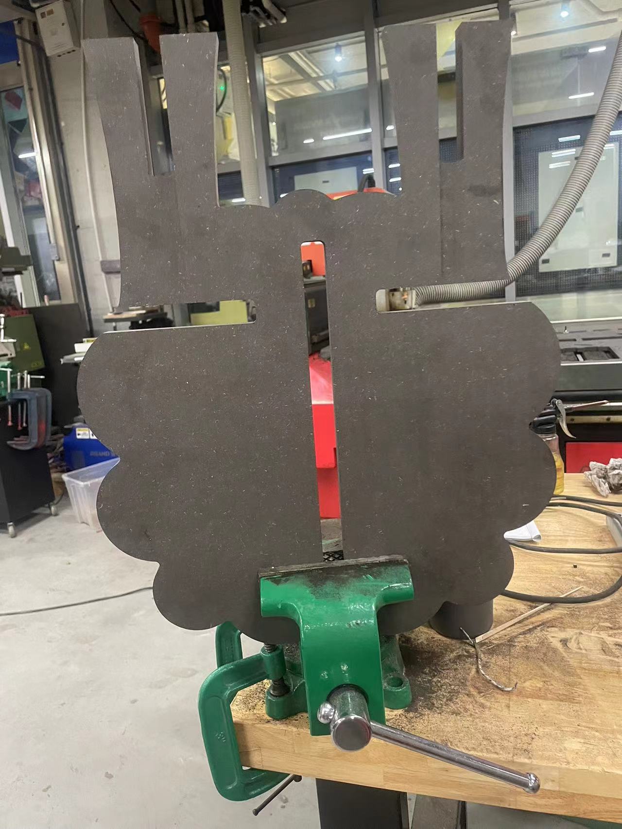
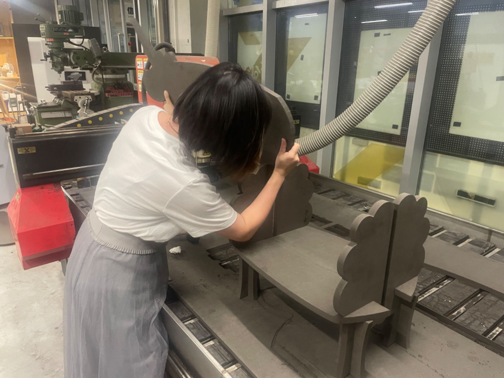
Splice the bottom plate and the front and rear plates
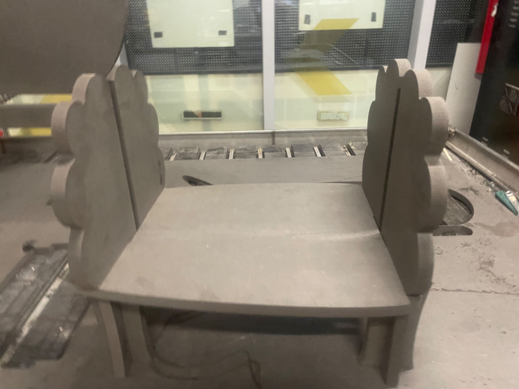
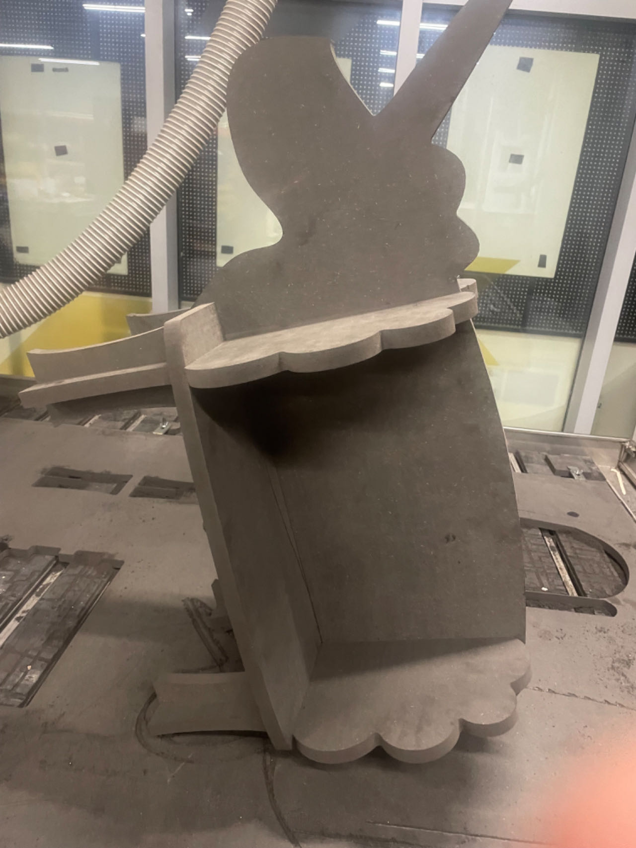
Finally, splice the middle board.
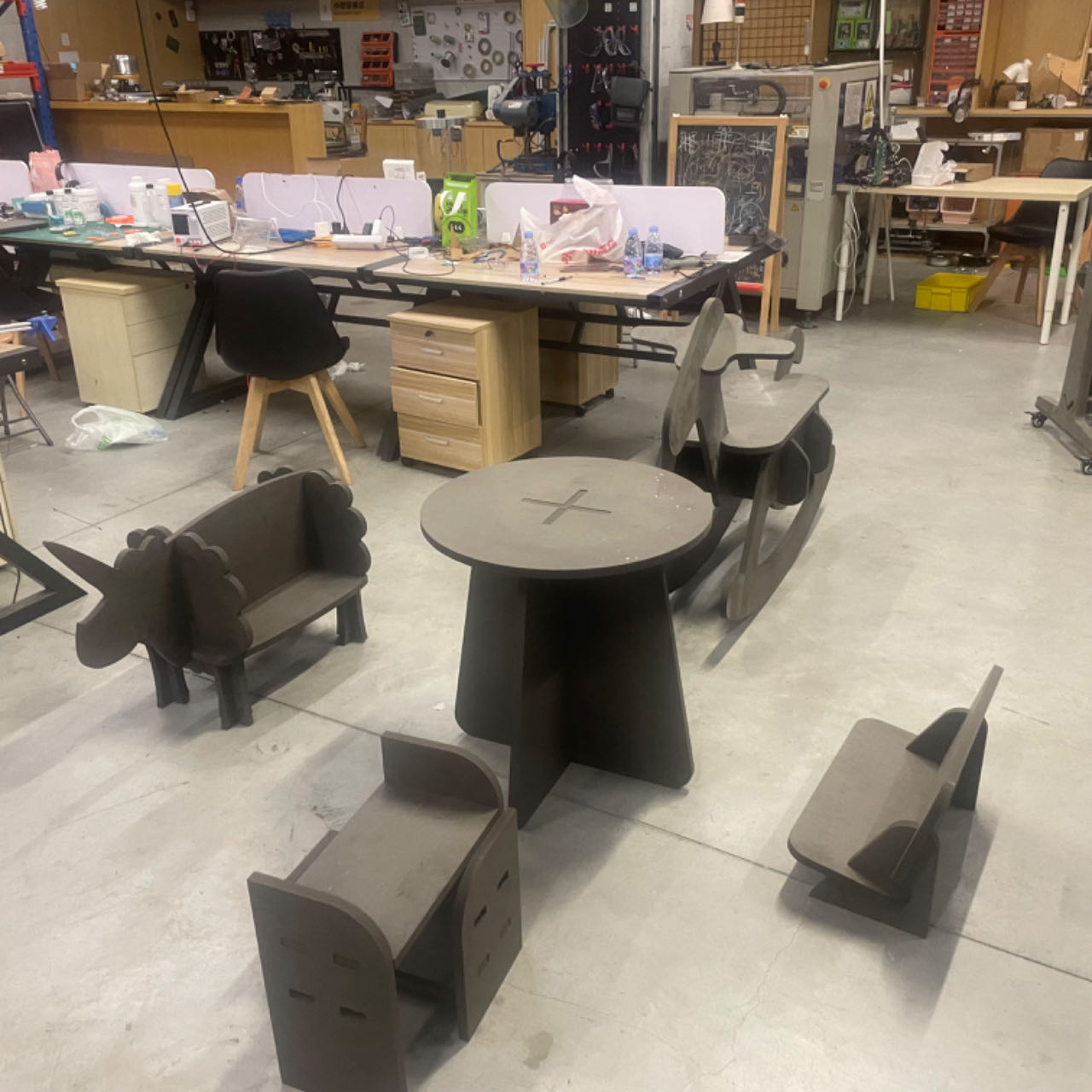
Here is a group photo of all our furniture!