Weekly assignments
- week 1. Project Management
- week 2. Computer Aided Design
- week 3. Computer Controlled Cutting
- week 4. Electronics Production
- week 5. 3D Scanning and Printing
- week 6. Embeded Programming
- week 7. Computer Controlled Machining
- week 8. Electronics Design
- week 9. Output Devices
- week 10. Mechanical design & Machine Design
- week 11. Break & Midterm Review
- week 12. Input devices
- week 13. Molding and Casting
- week 14. Networking and communications
- week 15. Interface and application programming
- week 16. Wildcard week
- week 17. Applications And implications
- week 18. Project Development
- week 19. Invention, Intellectual Property and Income
- week 20.Final Project Requirements
Introduction of My Final Project
1.Final Project Presentation
1.1 Final Project Slides

1.2 Final Project Video
2. Where is idea comes from?
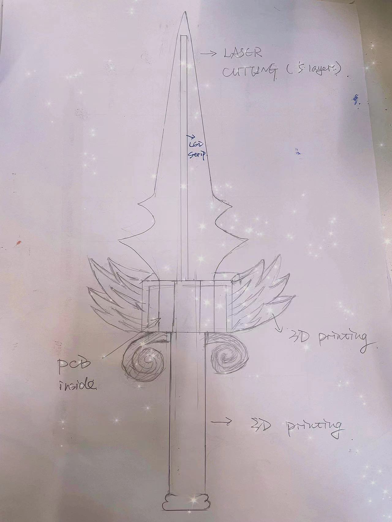
2.1 Sketch of the sword design
2.2 Function and application definition
3. Implementation of the project
3.1 Planning
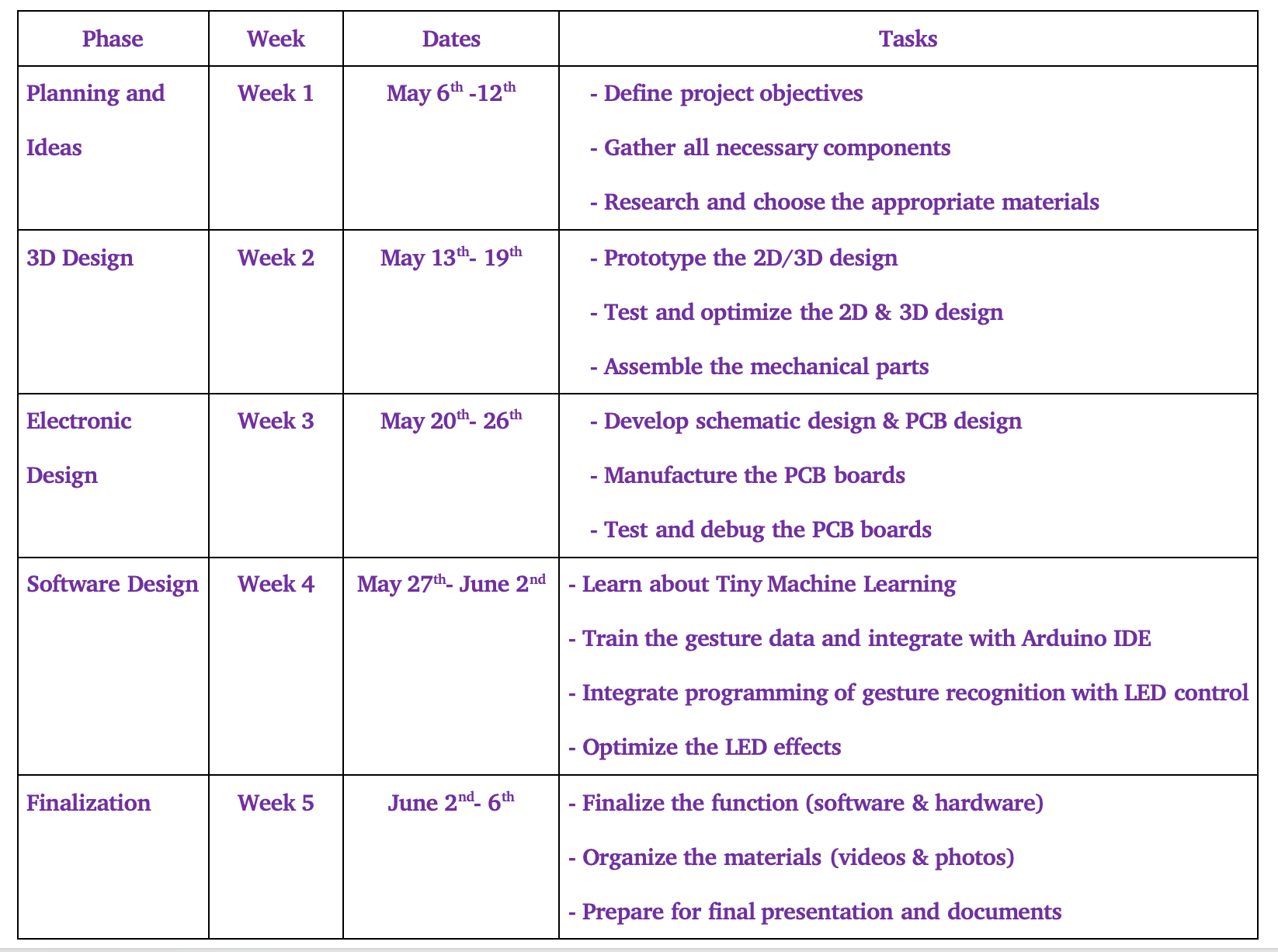
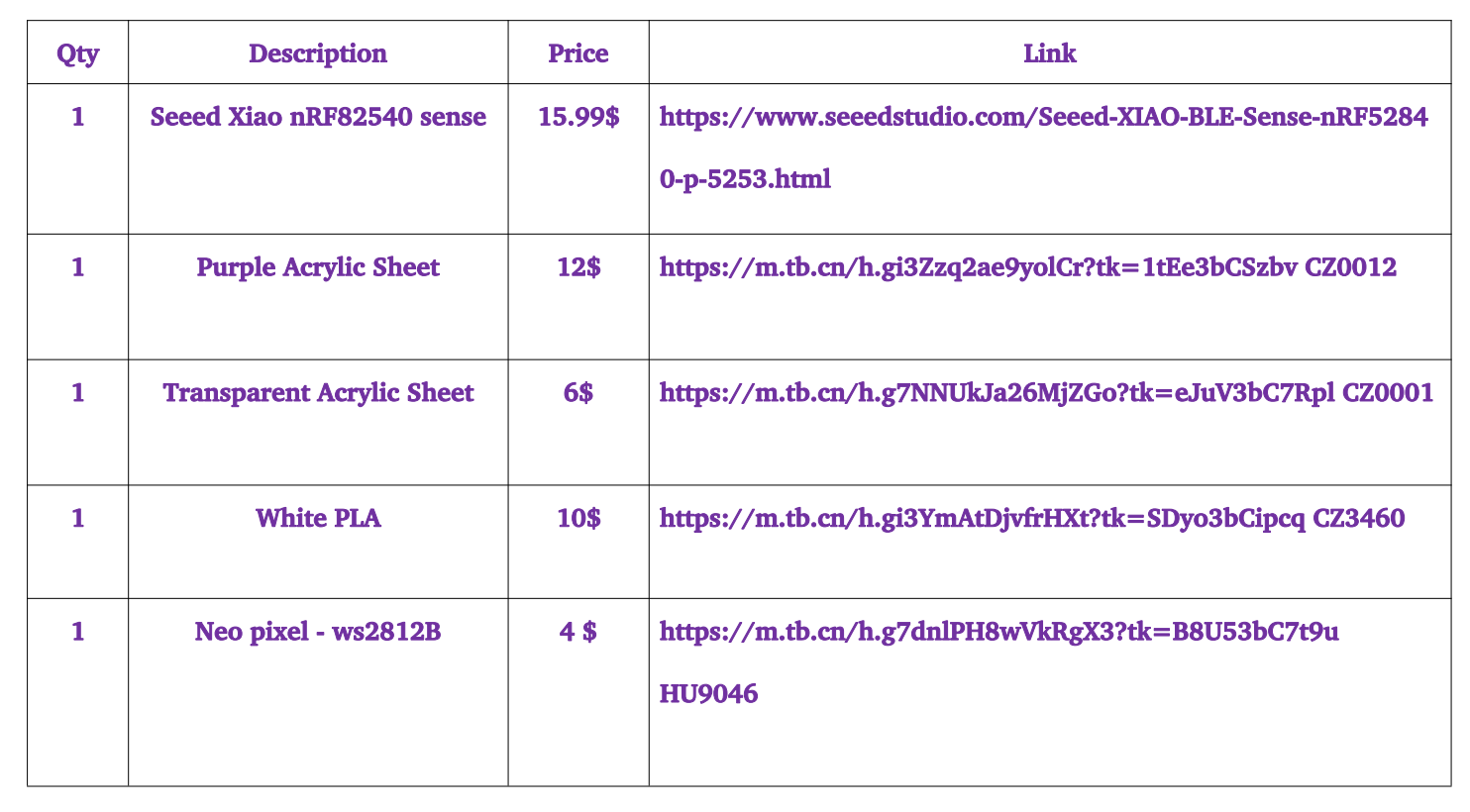
3.2 Material Procurement
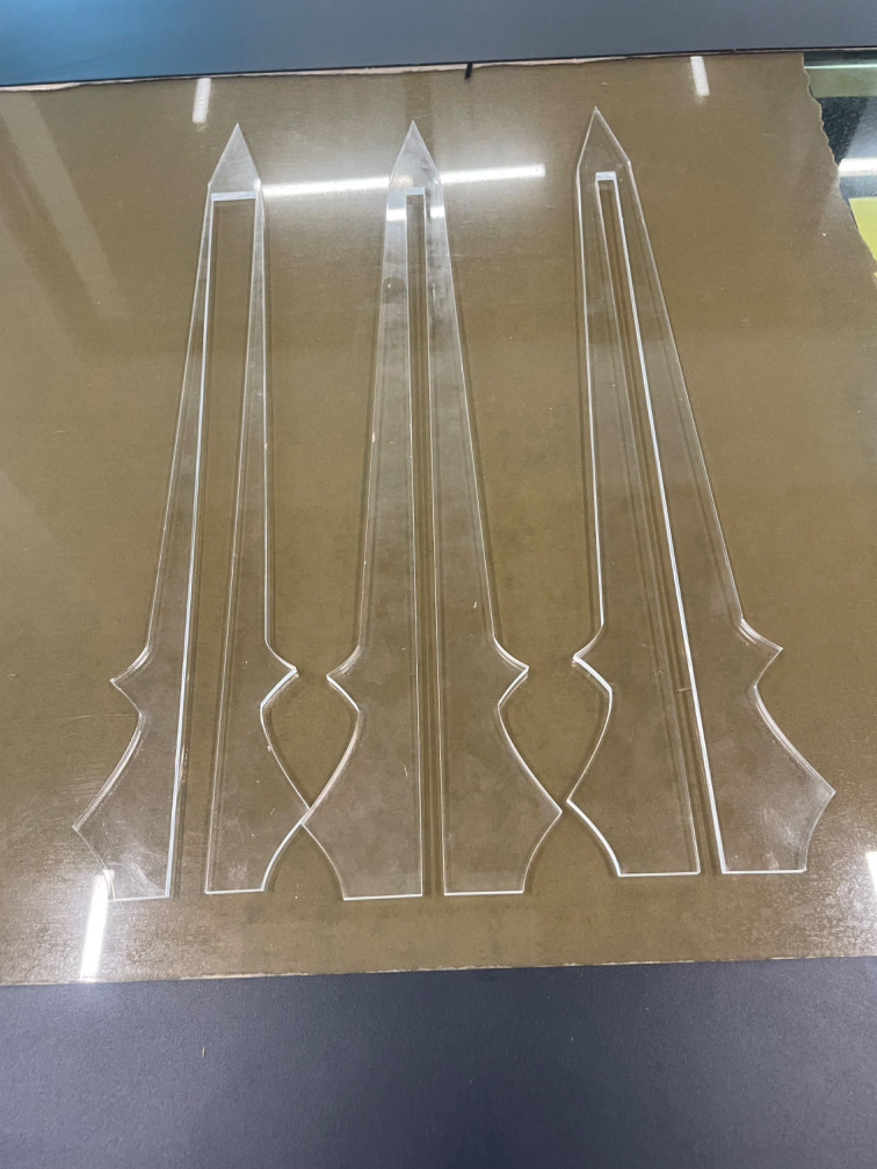
3.3 Laser Cutting Part
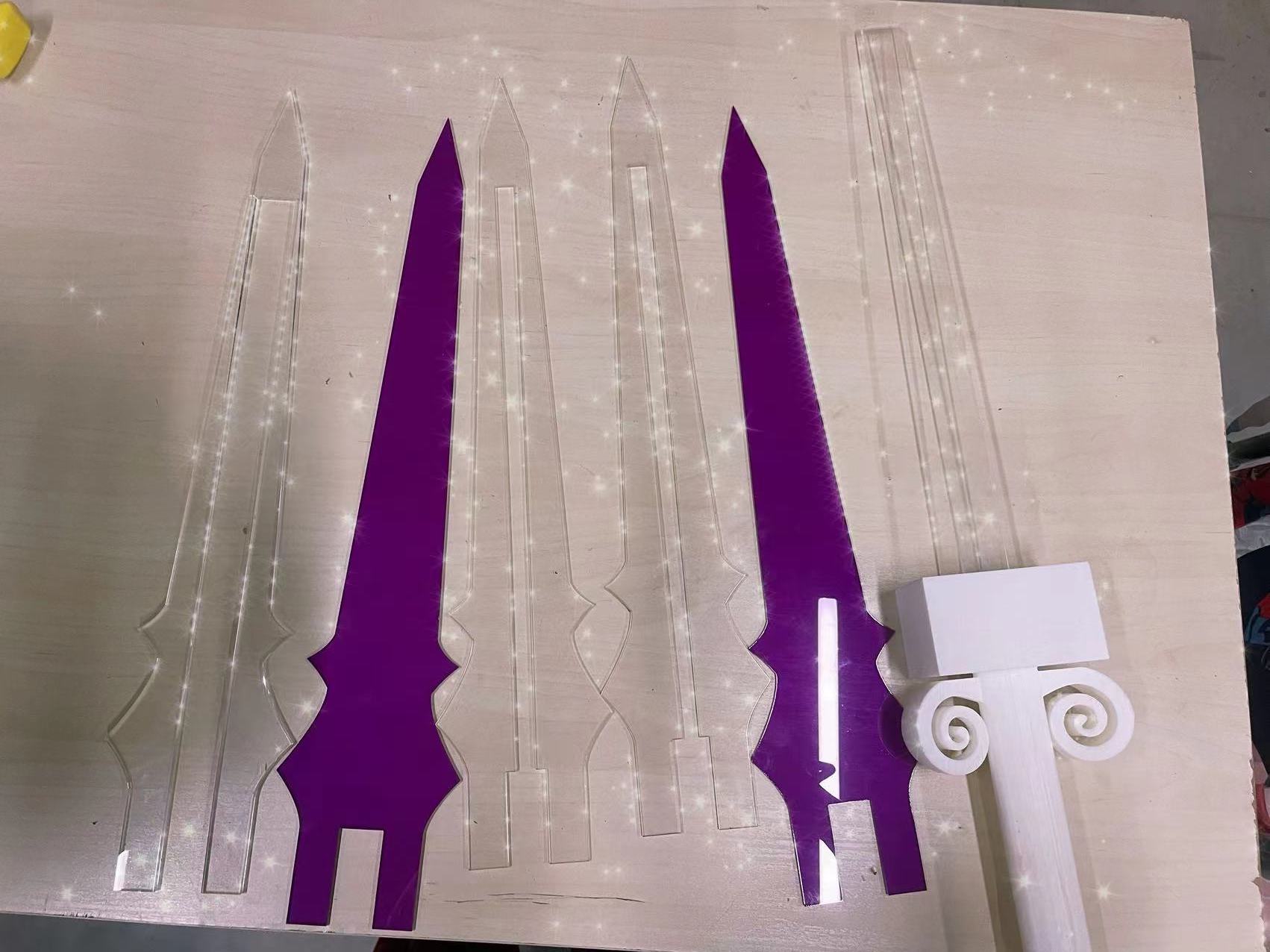
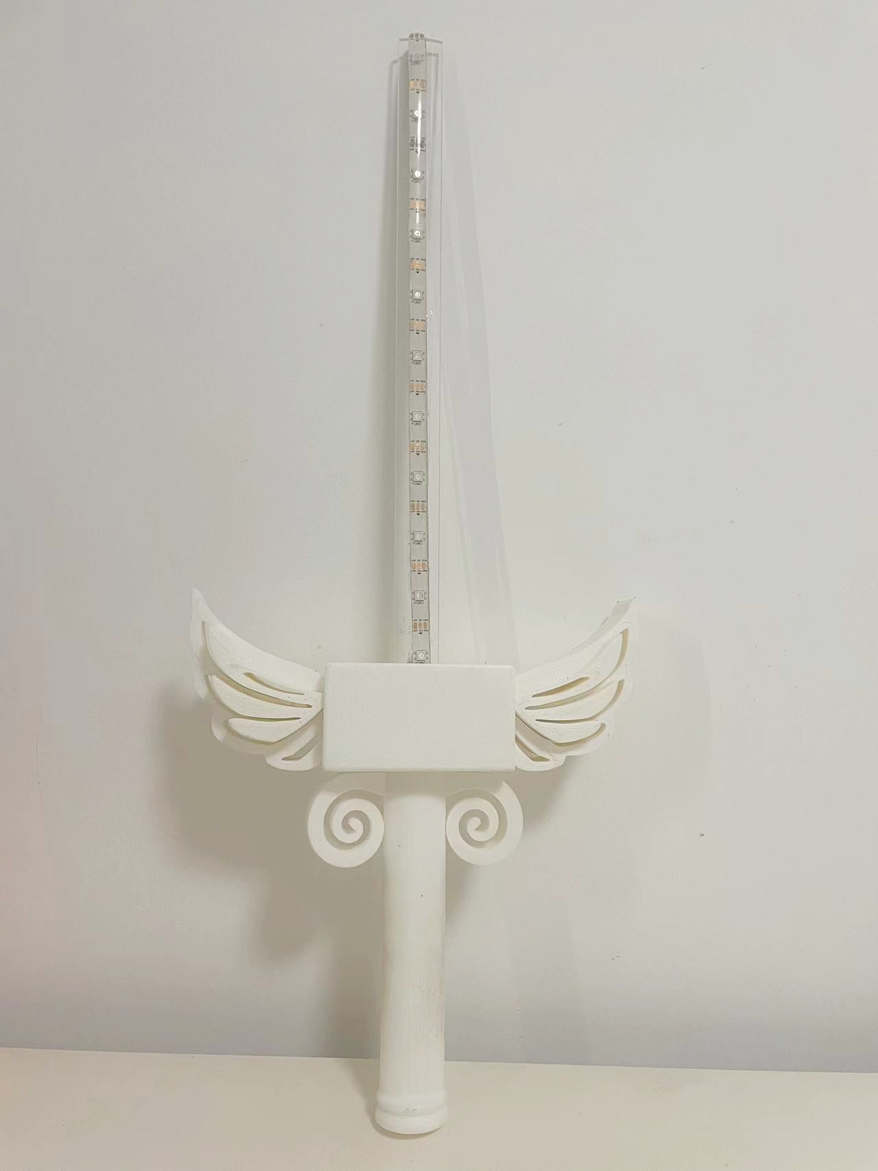
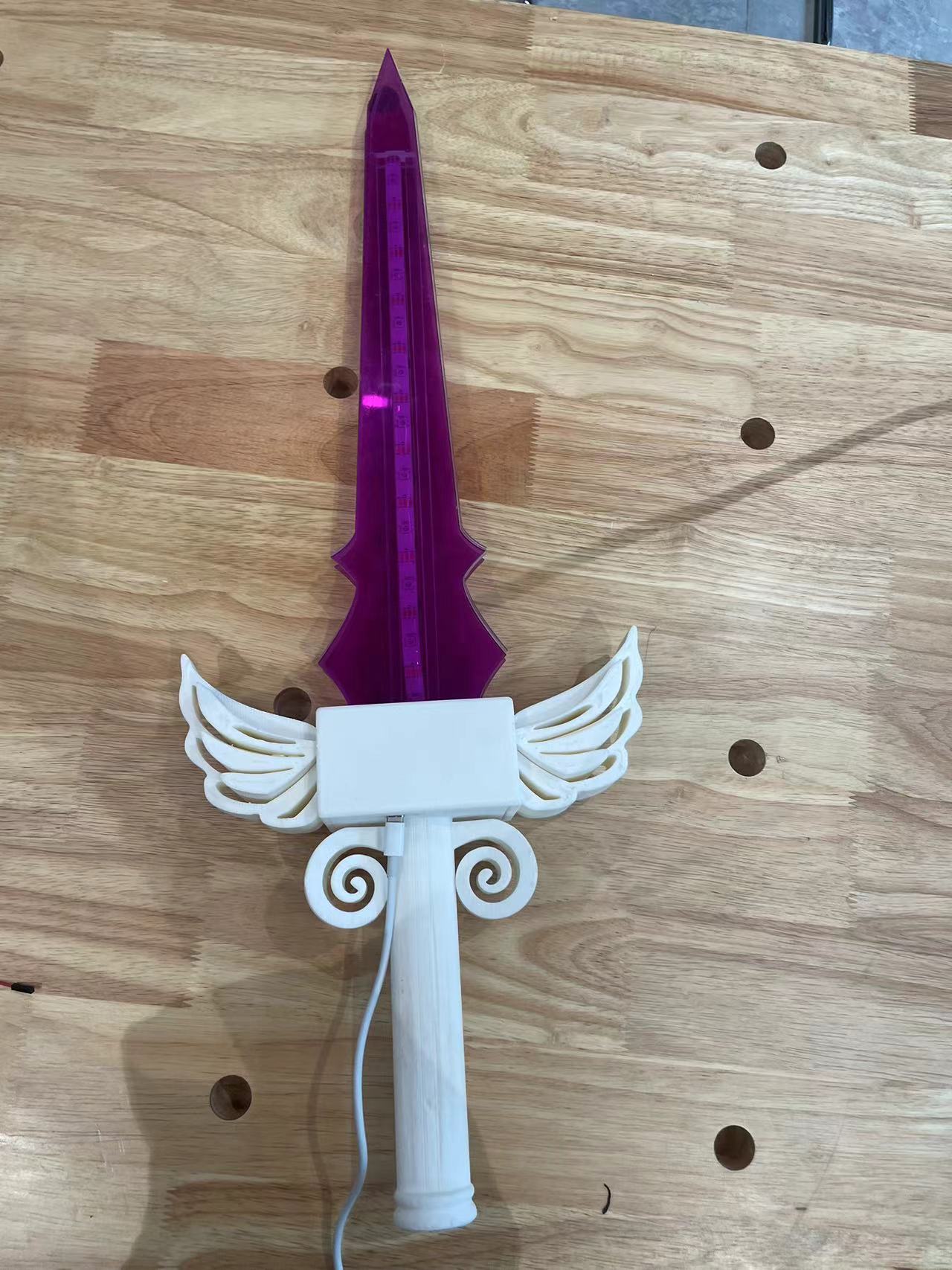
The sword blade is divided into five layers to embed the LED strips and connector inside. And two purple outer layers to make it look neat and beautiful. The important thing is to measure the thickness and width of the LED strips first to make proper design of my blade.
• The middle layer will also include the connector part, so I used a transparent acrylic of 5mm thickness to make it more robust to connect all parts.
• The thickness of my LED strip are 3mm, So I chose 3mm Acrylic board for the second and fourth layer of blade to make the whole sword lighter.
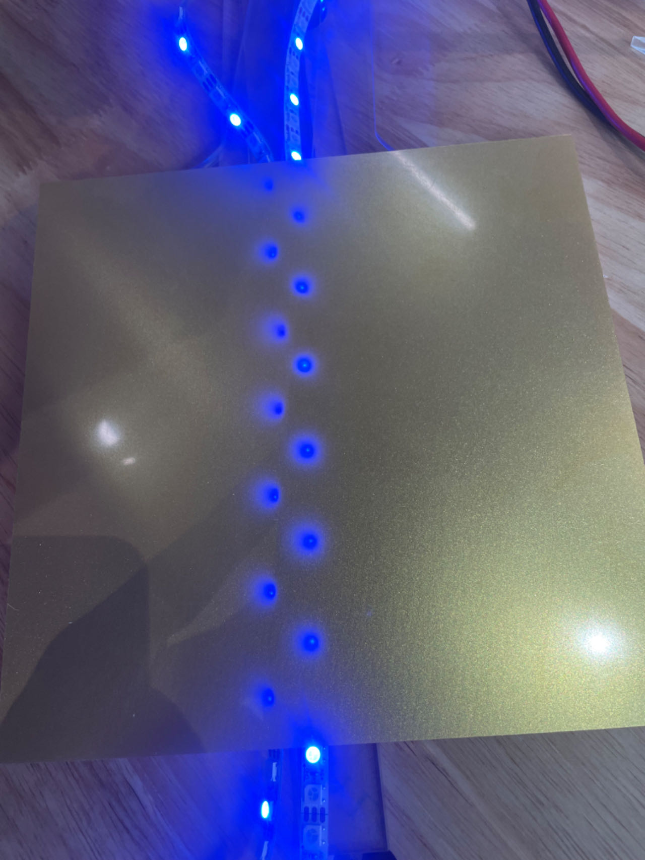
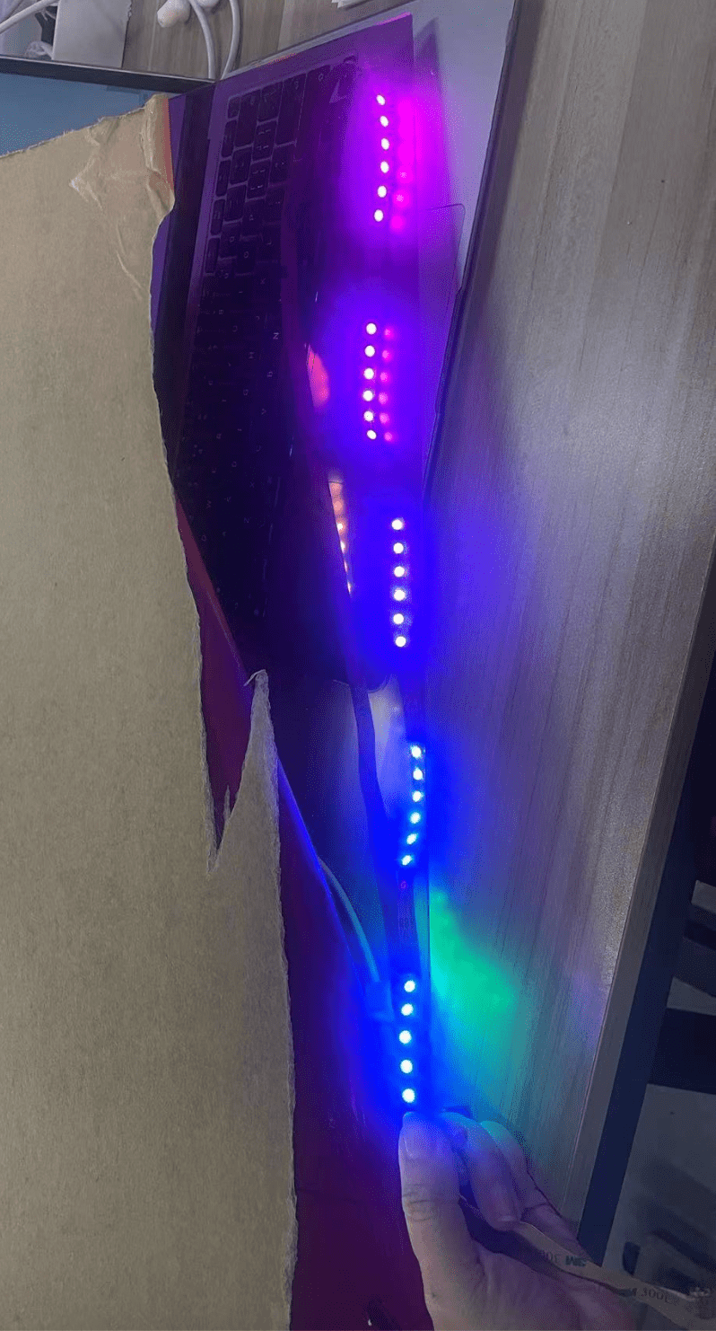
• The first and fifth layers serve as the outermost protective layers. They are required to possess a certain level of light transmittance while also presenting an aesthetically pleasing appearance. My initial conception was to employ a golden casing; however, that gold color failed to offer sufficient light transmittance. Consequently, I ultimately opted for the enigmatic purple hue.
• Test the light transmittance of the outer layer, but it didn't work well. So for final, I go with the purple one.
3.2 Material Procurement
3.3 Laser Cutting Part
First Version of my blade part
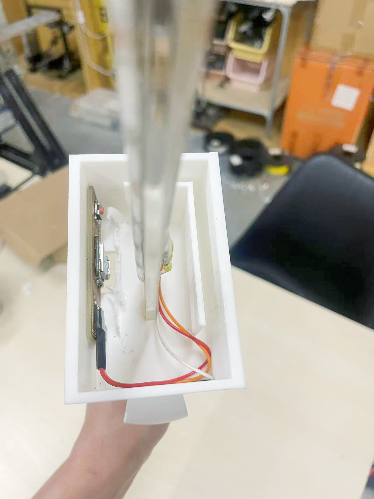
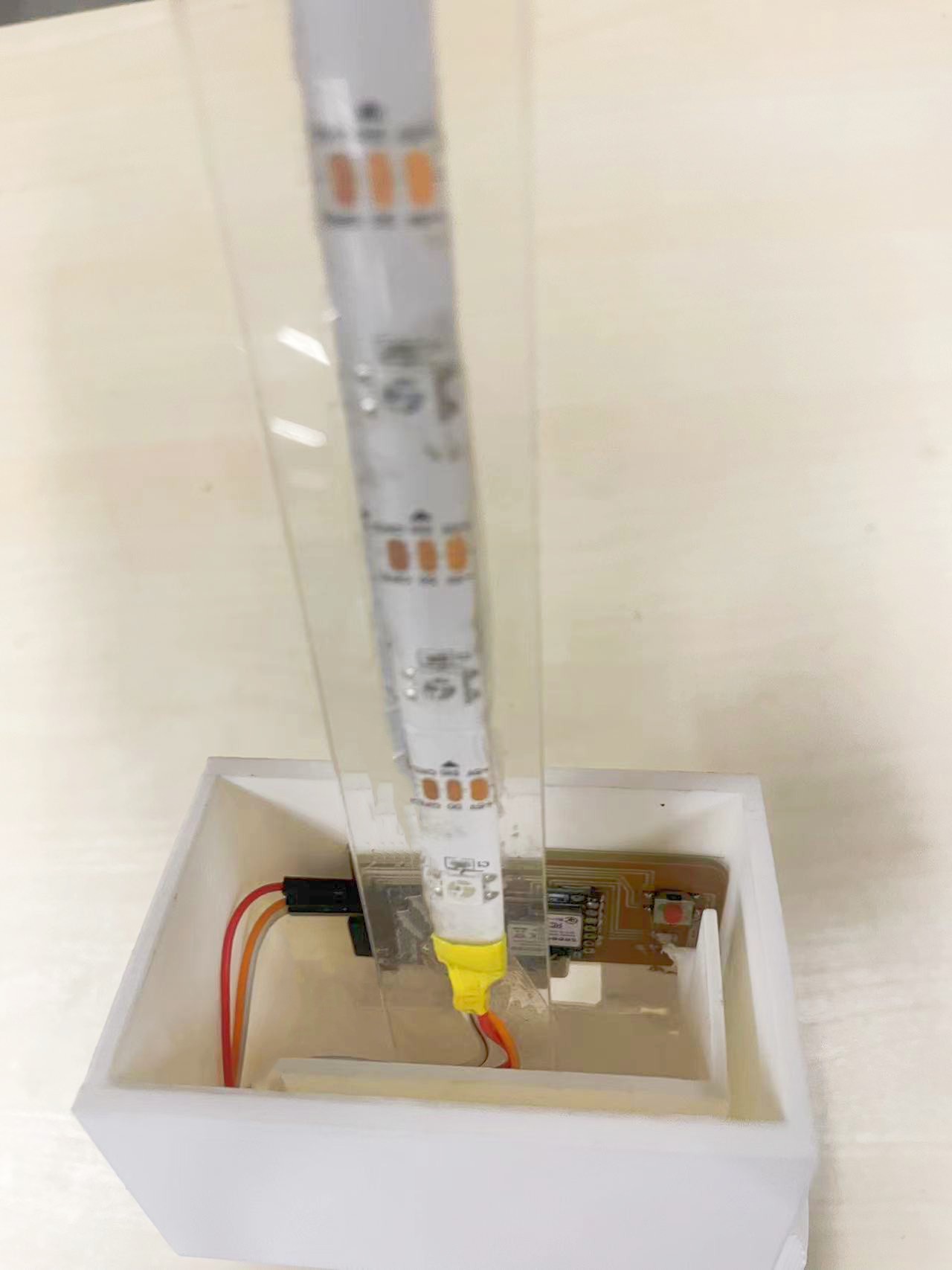
The initial concept for the laser cutting section was that only the connector of the middle layer would be inserted into the sword case for connection. Nevertheless, upon printing out a version of the sword case, it was discovered that such a connection was not stable. Consequently, the design was modified. All layers were extended to a certain extent and inserted into the sword case.
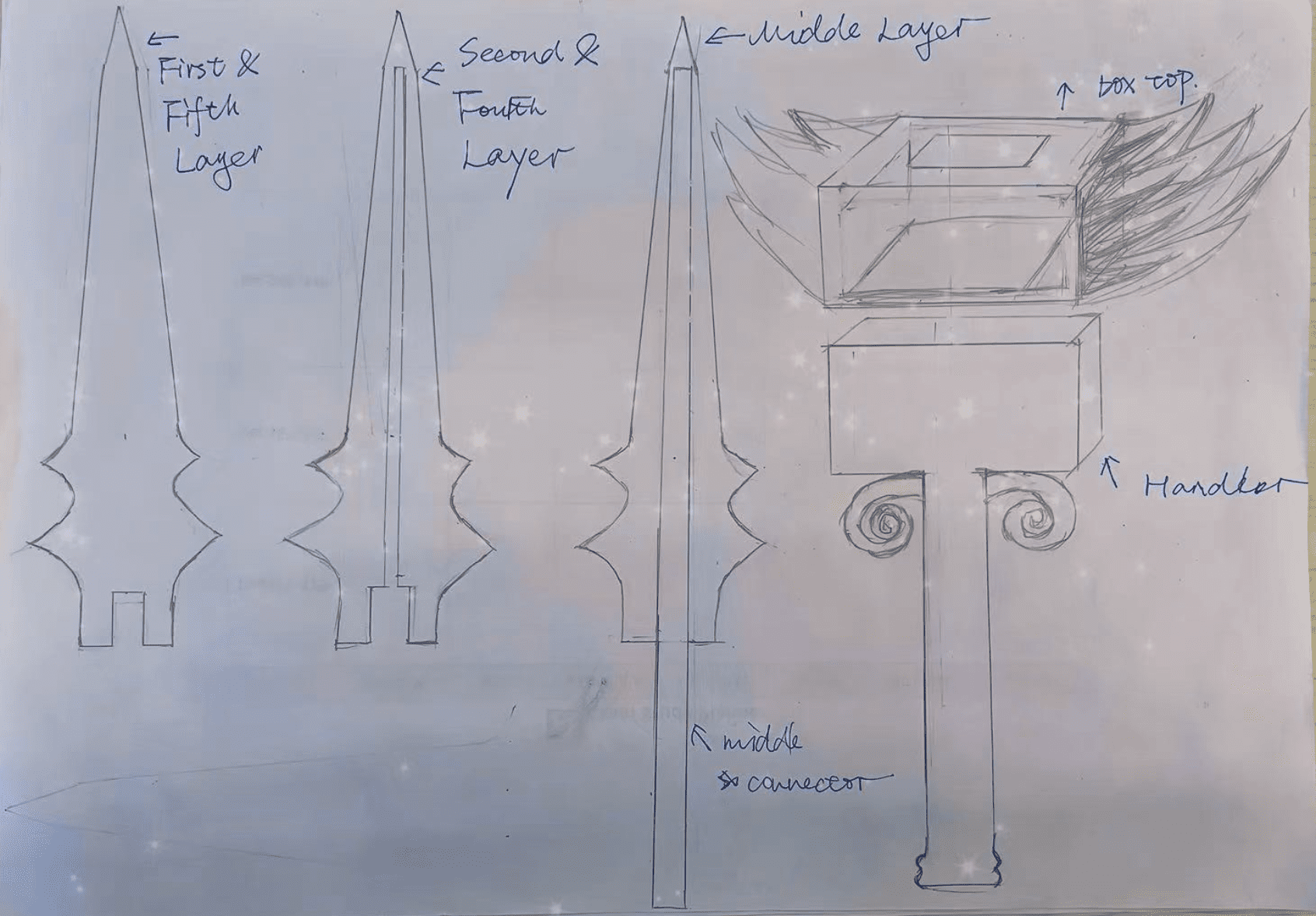
My new design sketch files:
The second and fourth layer
The middle layer including the connector to be cut.
Final cut of all five layers
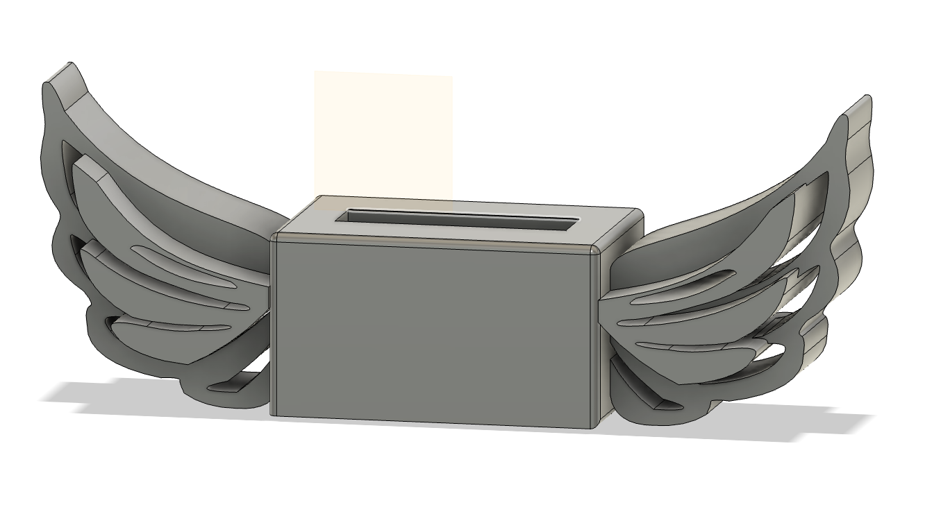
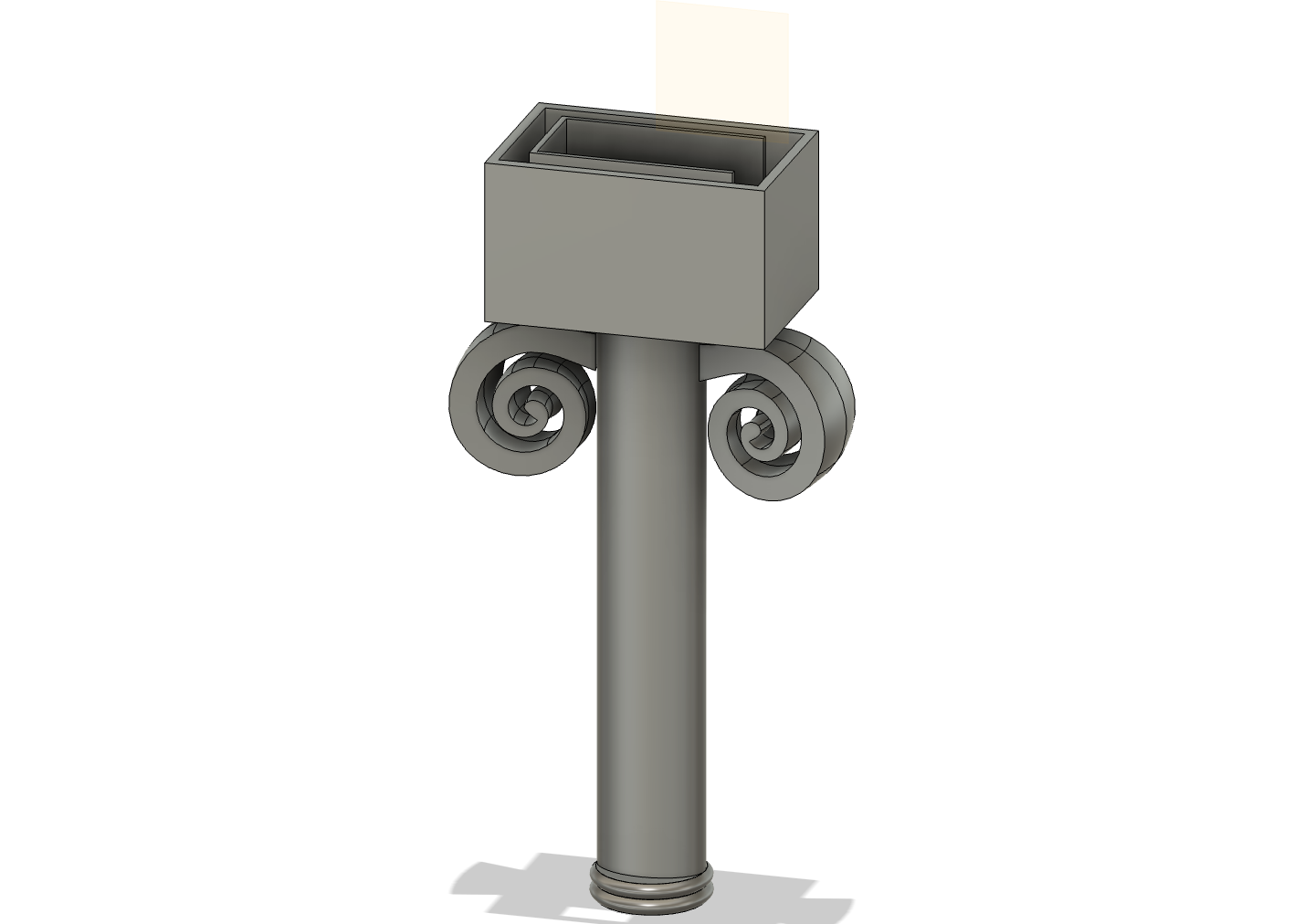
3.4 3D Design of the Sword Case and Handle
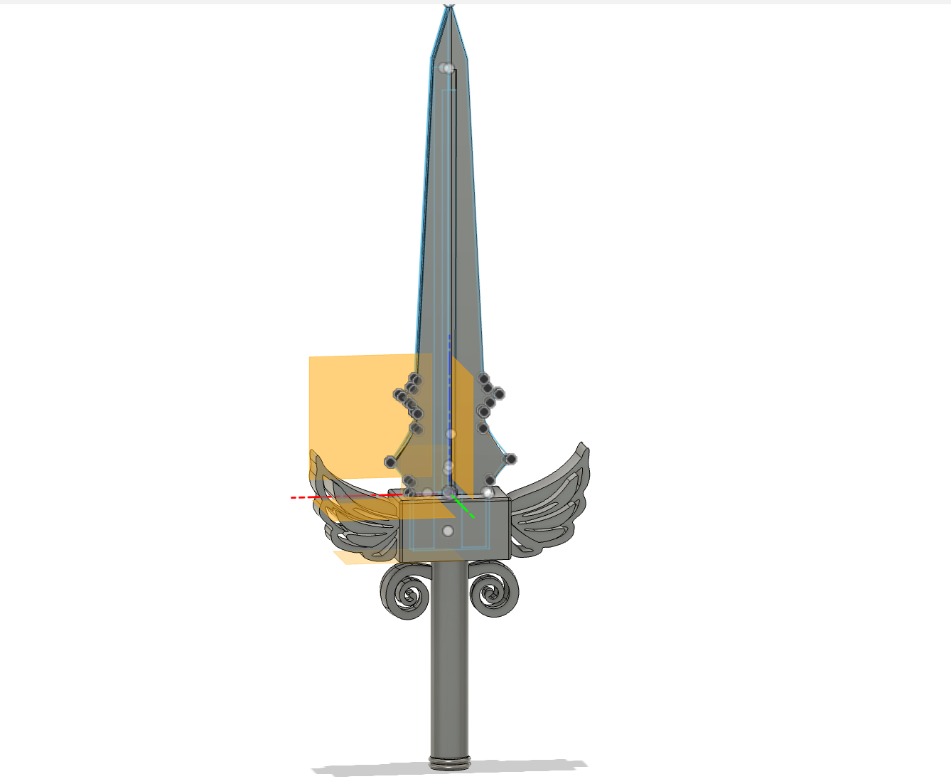
3.5 Circuit and Mechanical Design
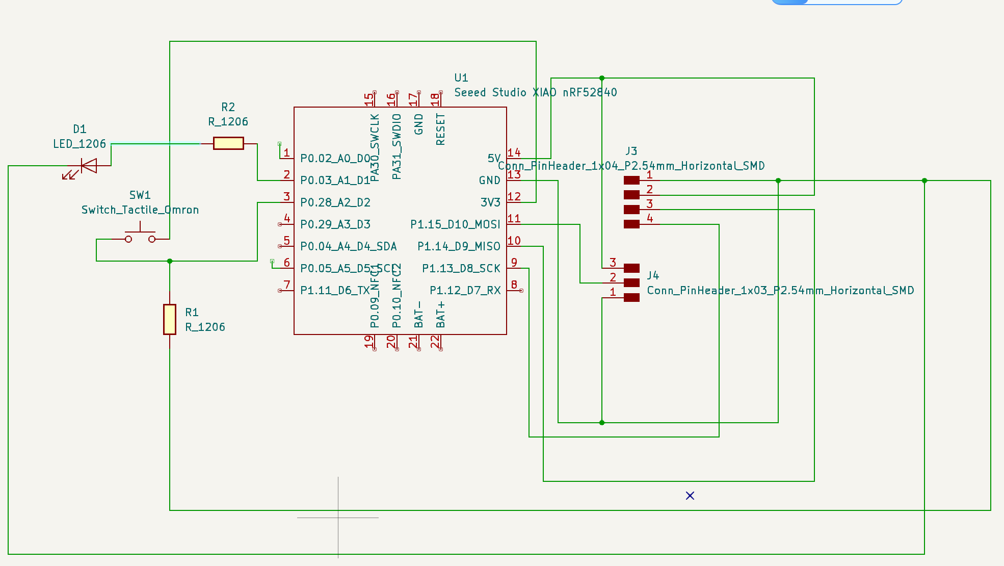
I used KiCad for my PCB design
3.5.1 The schematic of my final project PCB
Input PCB Design Rules

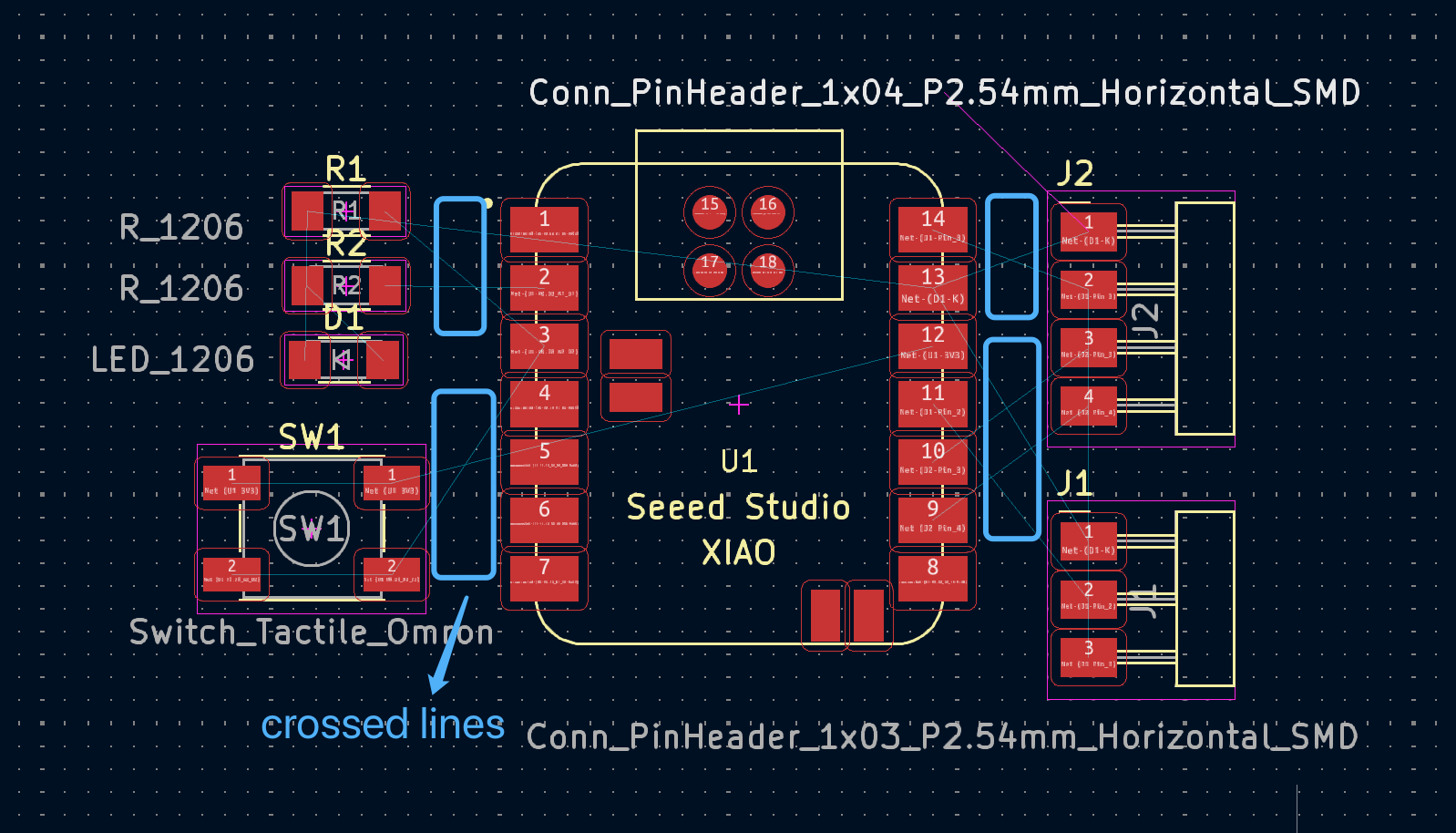
ReArrage all the components in PCB View
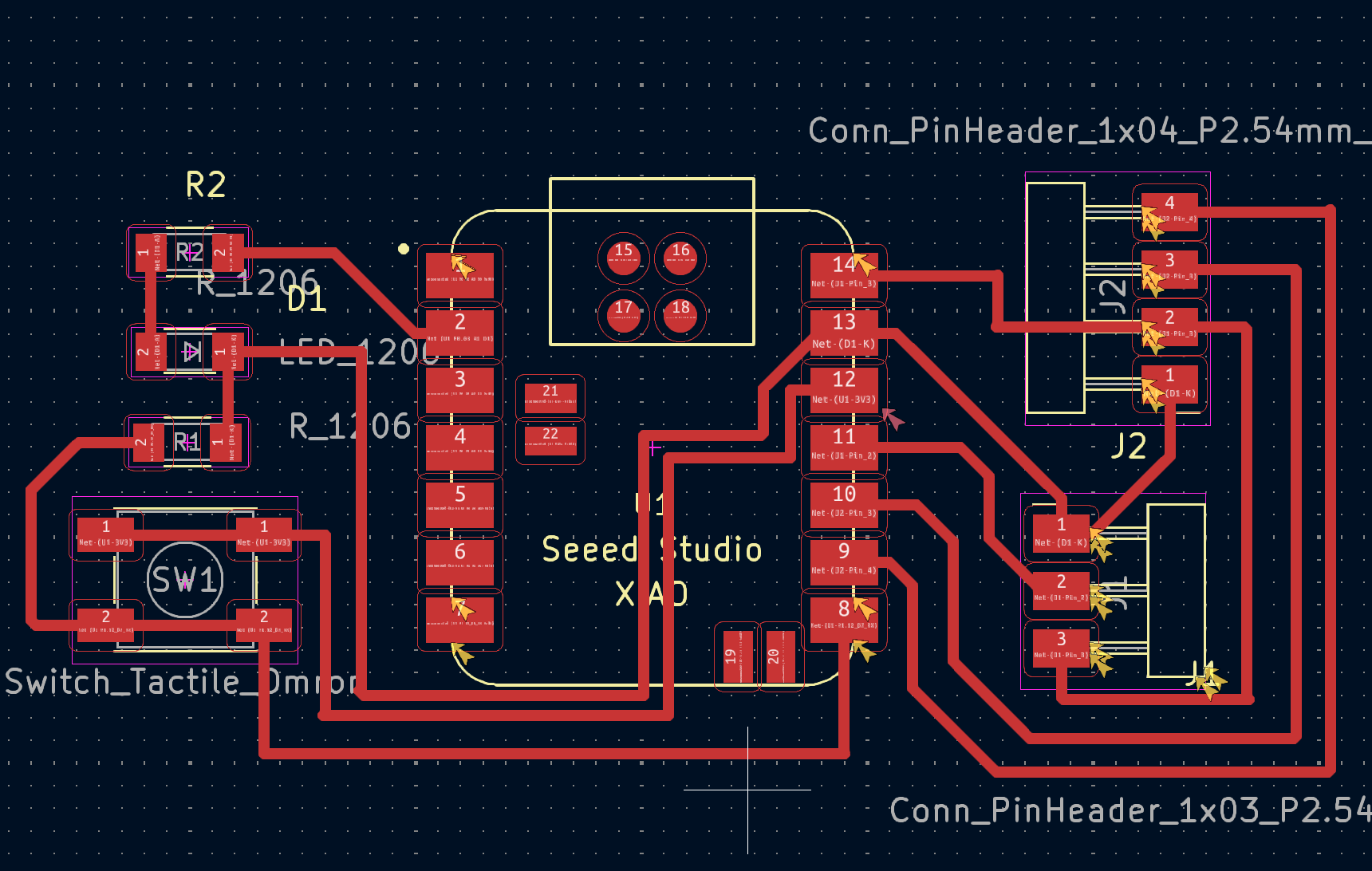
3.5.2 The Final PCB Design
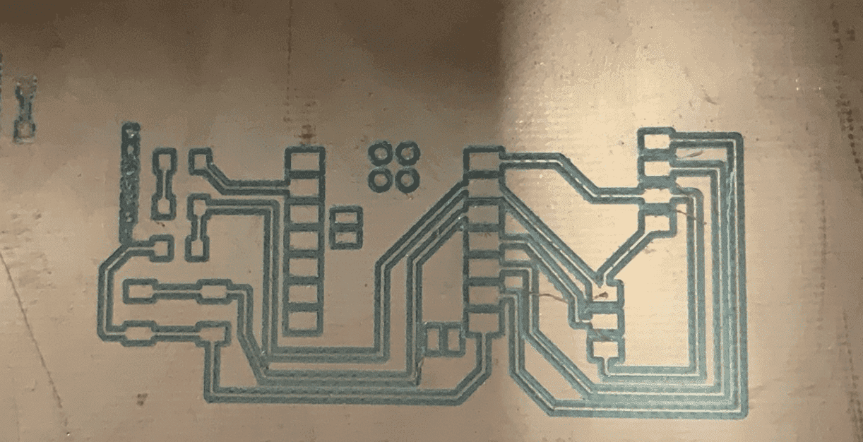
3.6 Mill the PCB
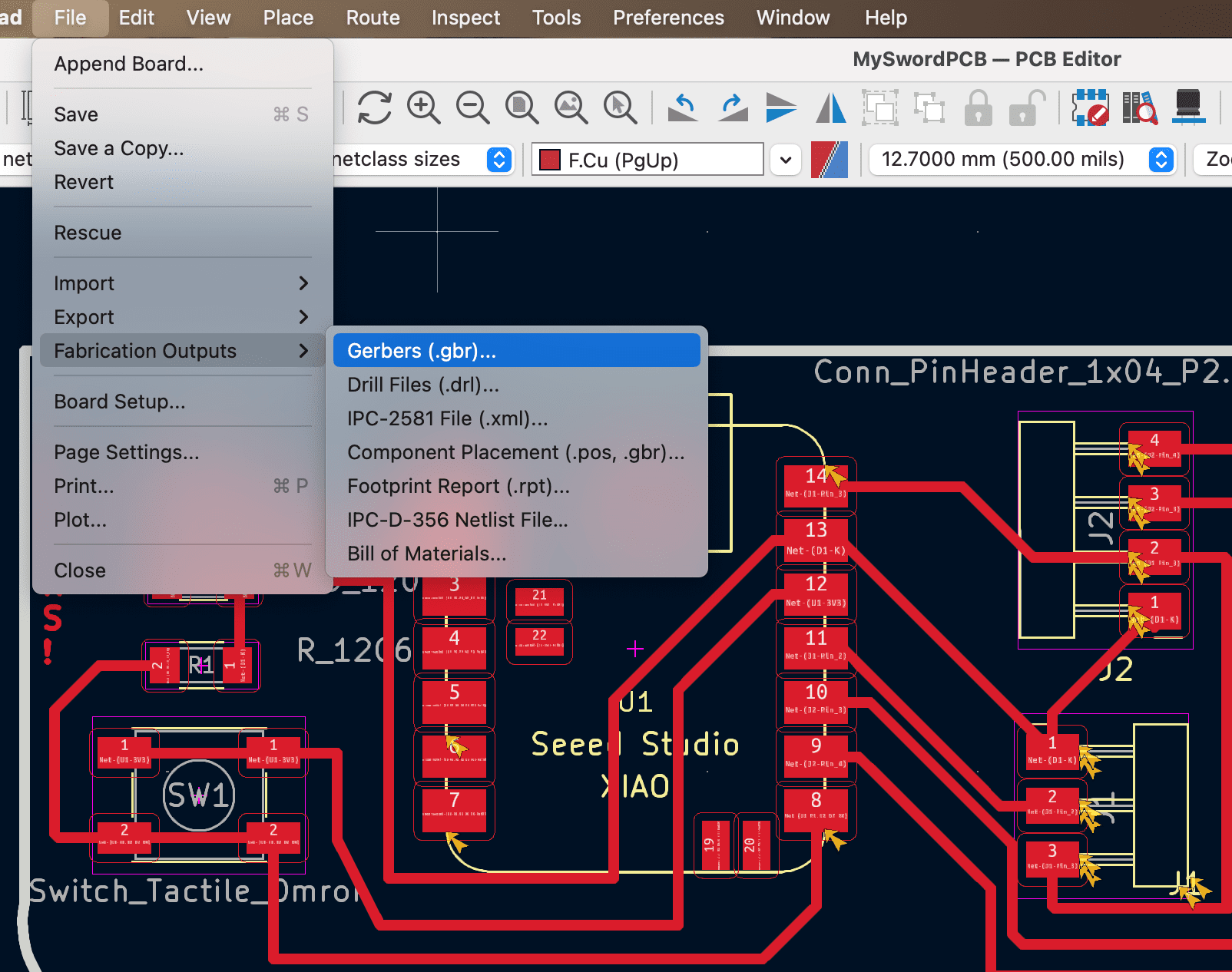
3.6.1 Generate Gerber files
3.6.2 Transfer Gerber file to PNG
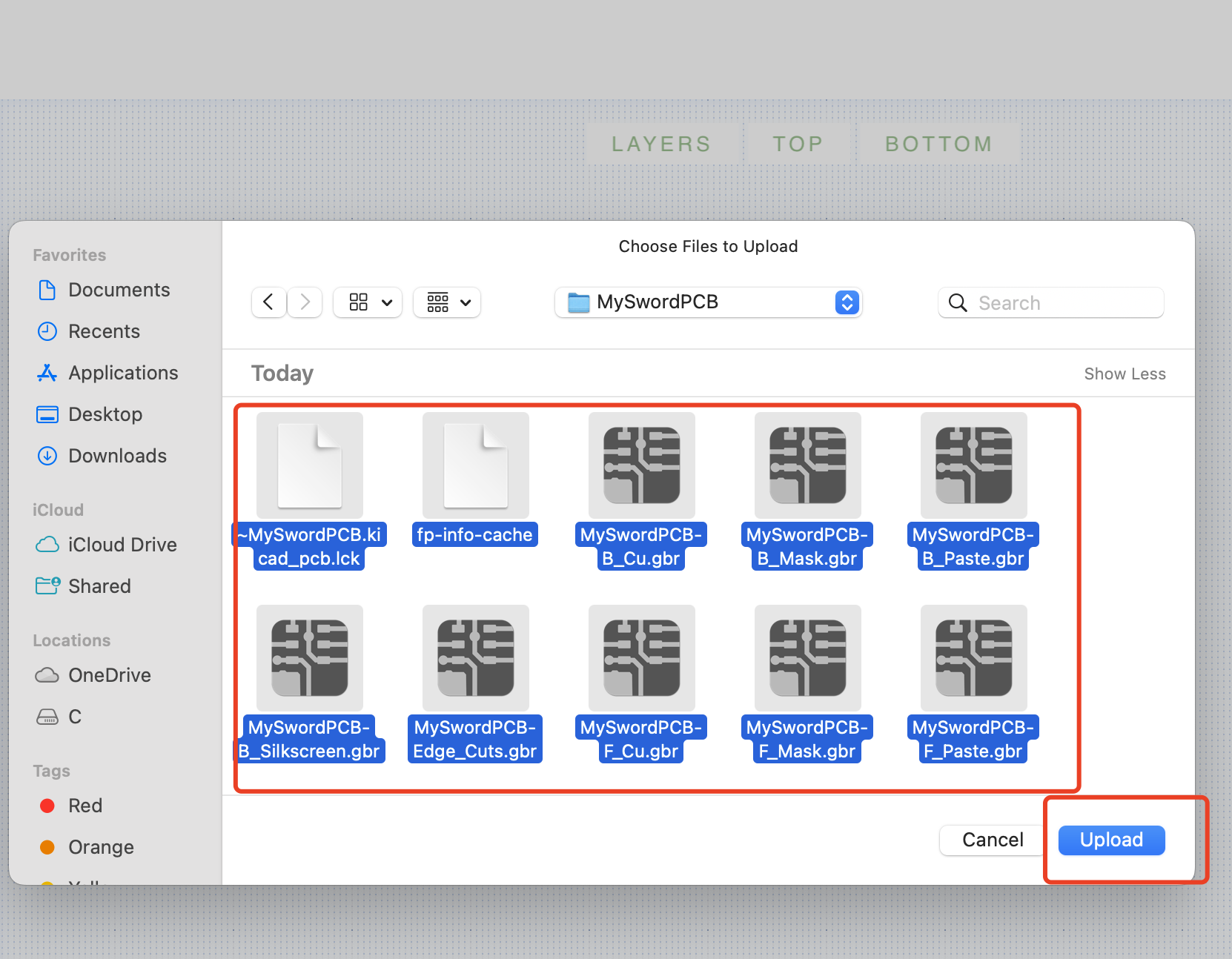
Select the topTrace and TopCut to generate corresponding png files.
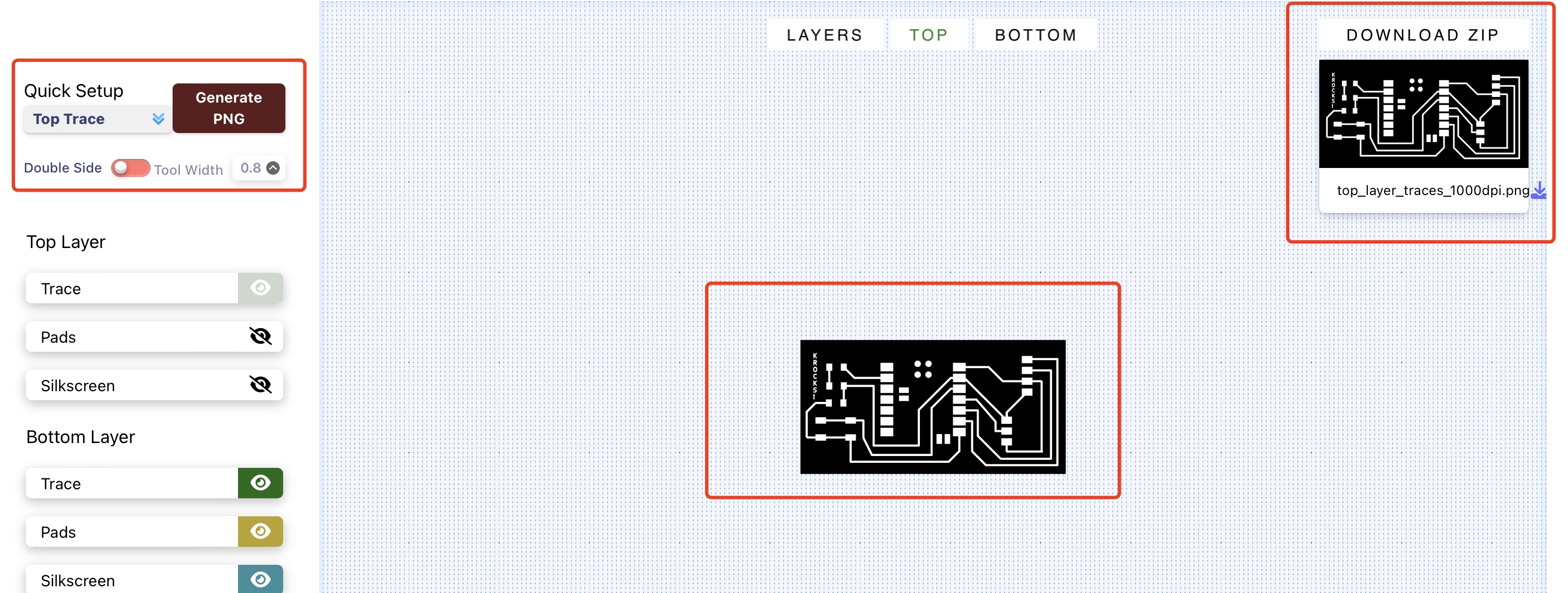

3.6.3 Generate the G-code Files using ModsCE
It is needed to generate diffrent G-code files for trace cutting, outline cutting and drill.
For the trace file, the parameter needed to be set are as below
Always remember to set the dpi to 1000
For the v-bit, you can also change the parameter based on the real v-bit you have choosen instead of
using the default parameter to get a better PCB. The V-bit I have choosen 20 20
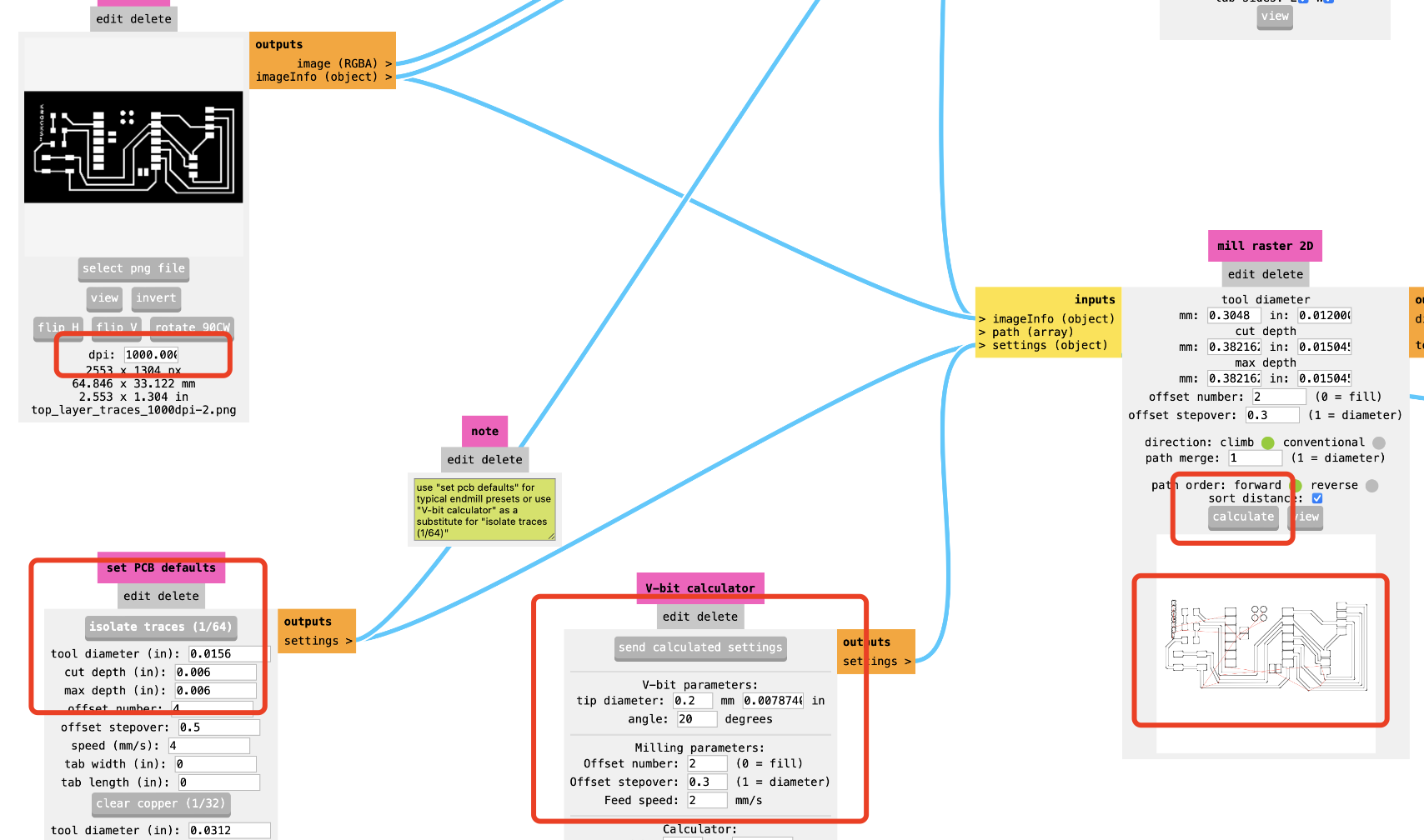
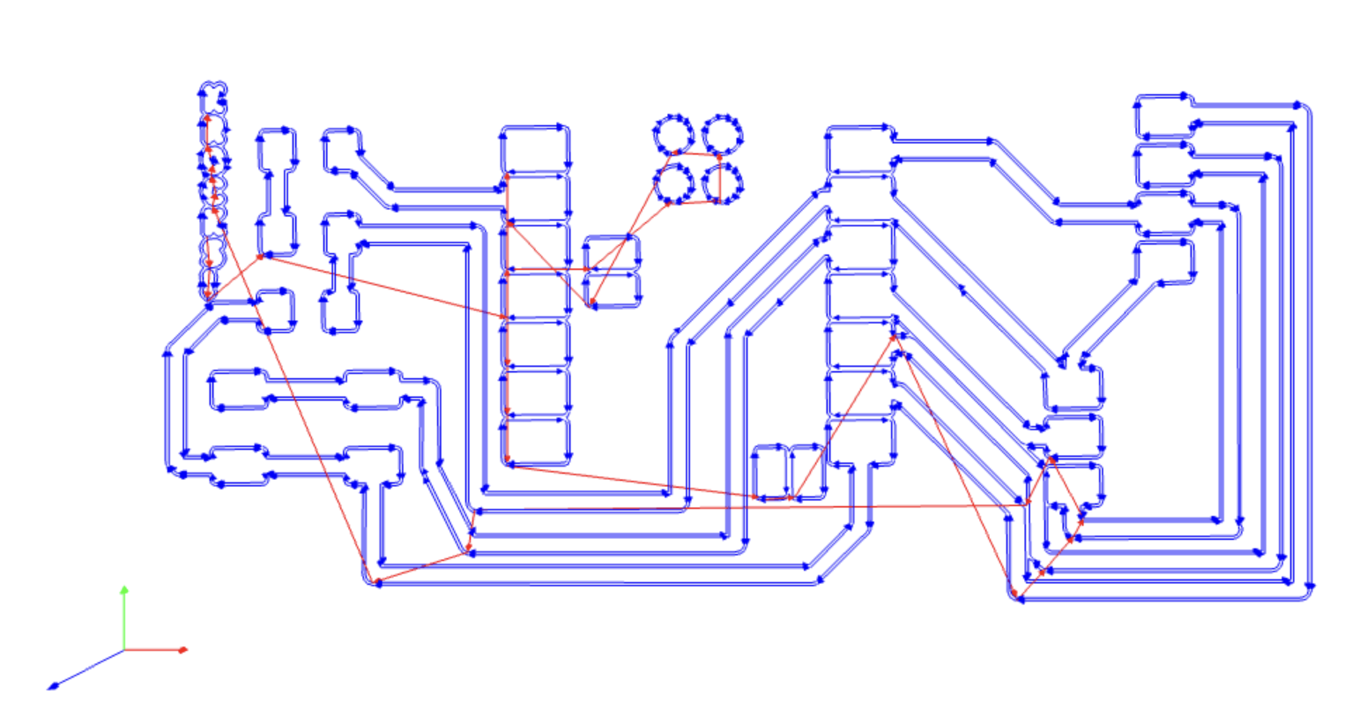
You can also preview the trace of cutting
For the outline file, the parameter needed to be set are as below:
Always remember to set the dpi to 1000
use the default parameter is fine.
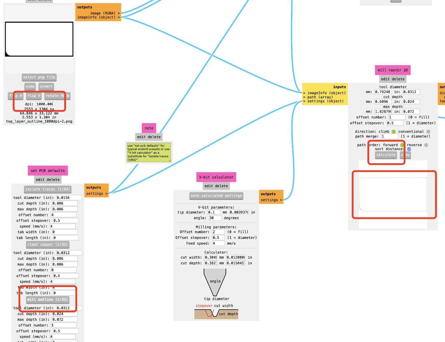
You can also preview the trace of cutting
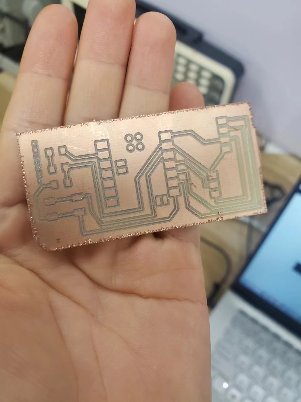
3.6.4 Machine Milling
For this part, all needed is follow the same steps as week04 and use the machine to mill the PCB
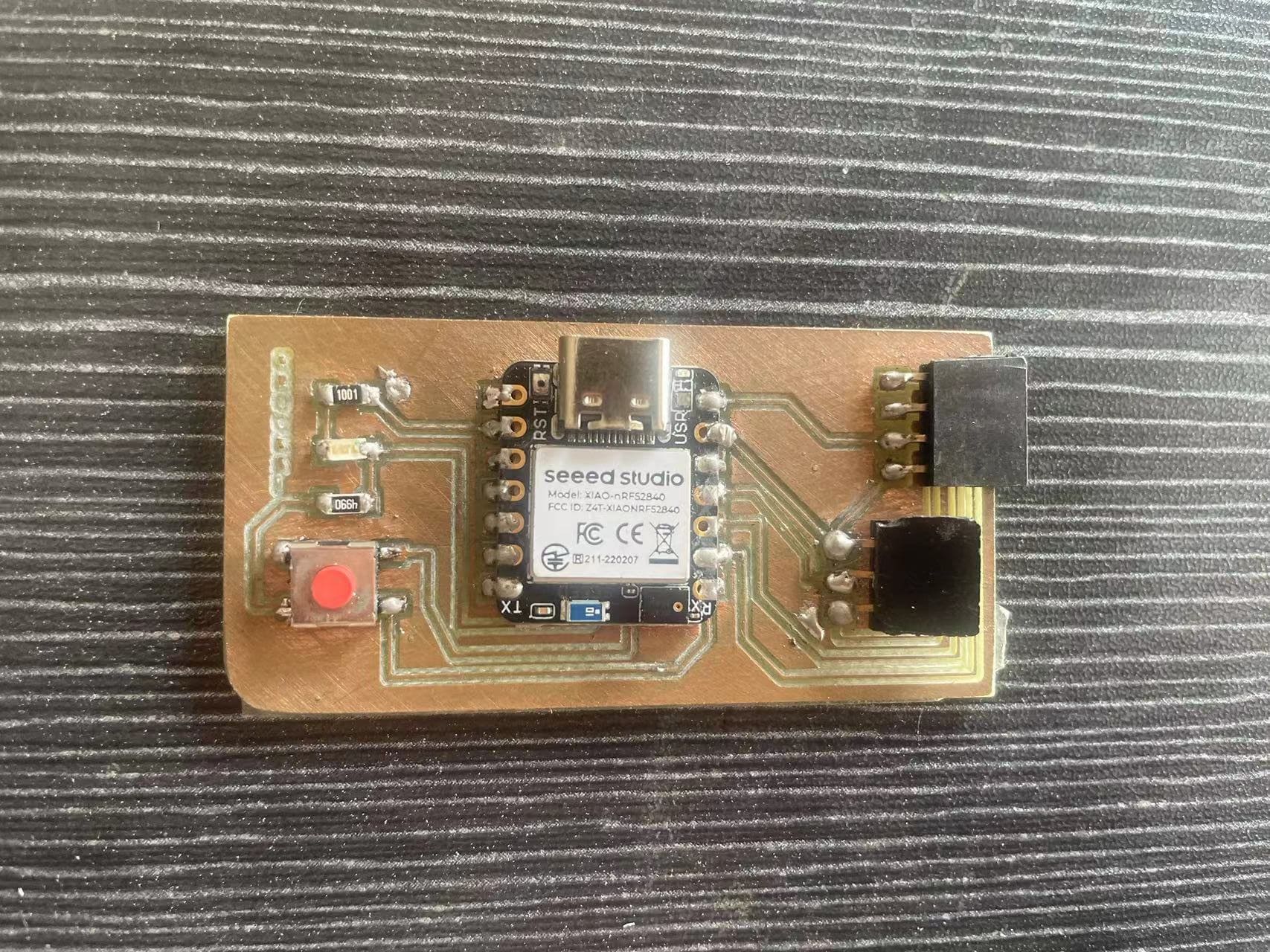
Step 8 Solder the Board
3.7 Tiny Machine Learning
3.7.1 Start to learn tiny machine learning
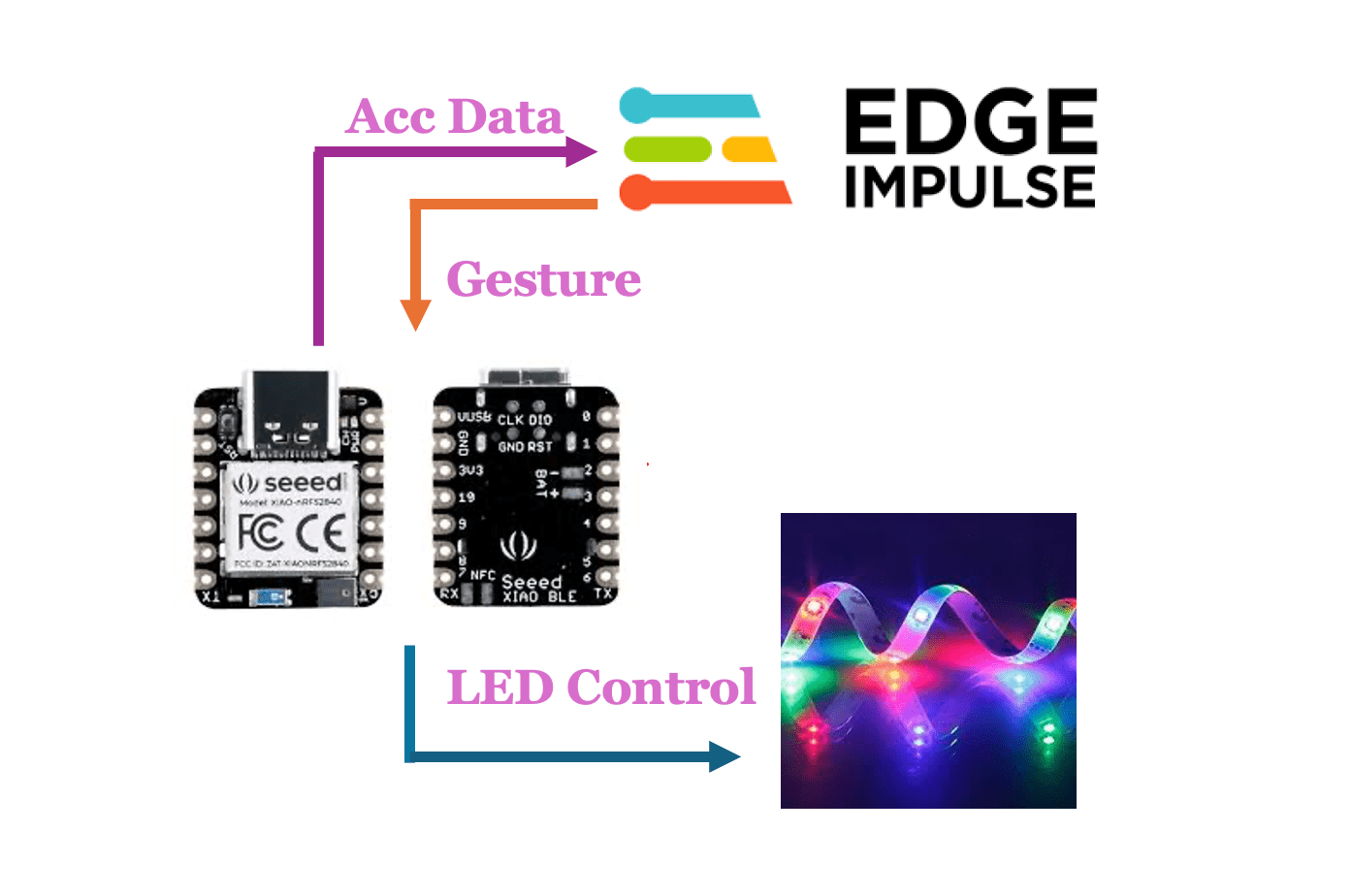
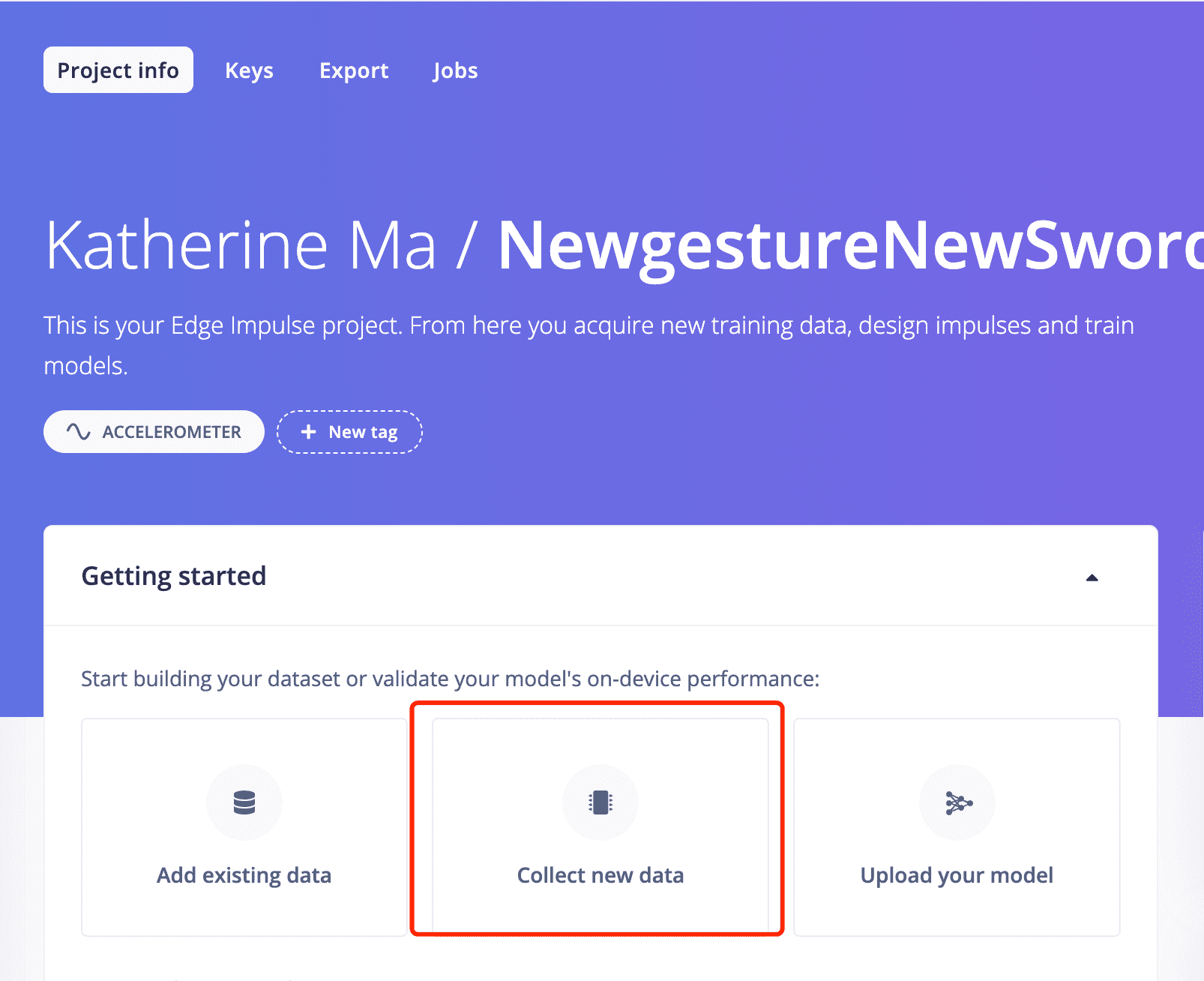
3.7.2 Use Edge Impulse to do Machine Learning
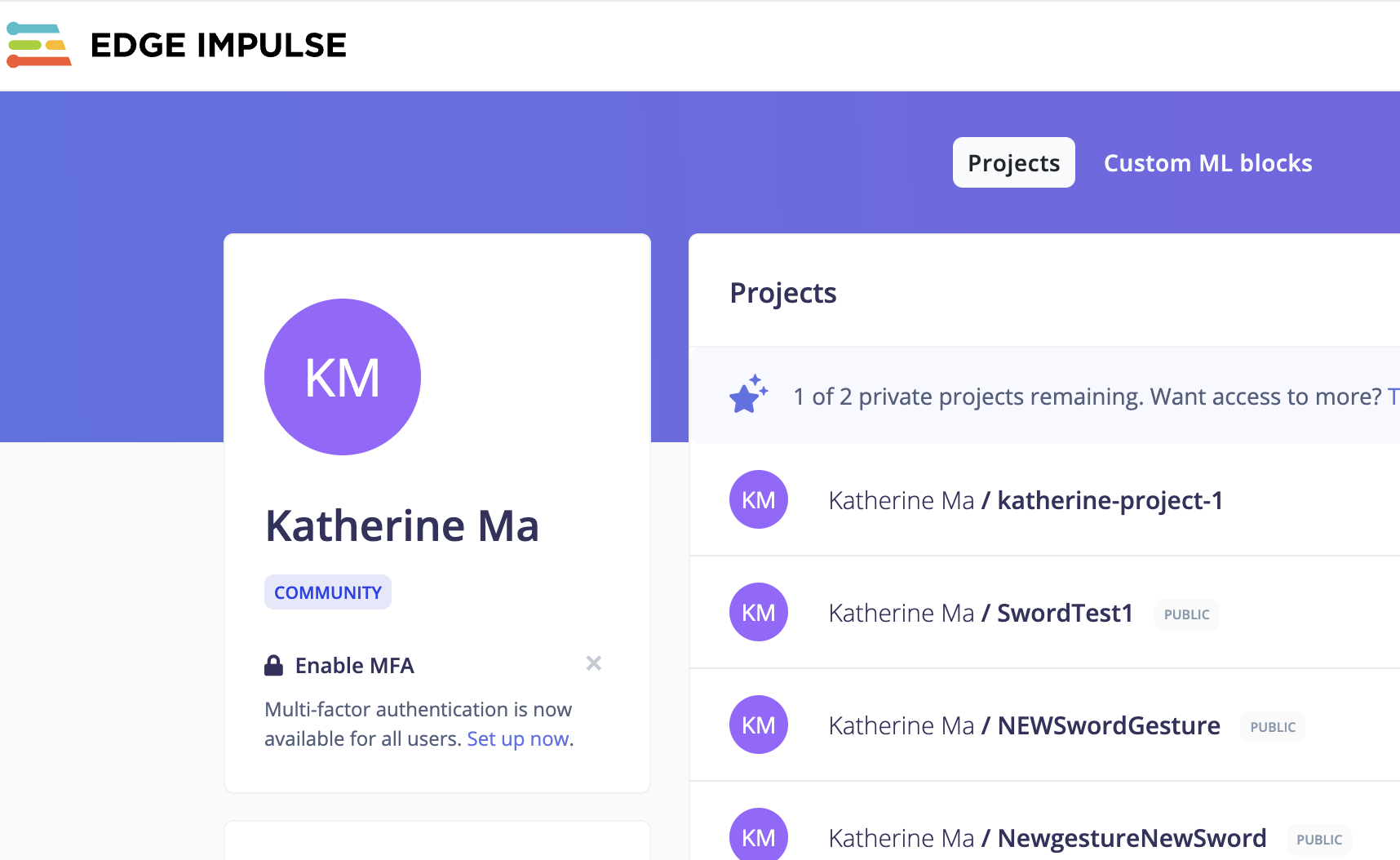
Step1. Install Edge Impulse, create account and set up new project for my sword.
Step 2.Prepare the nRF52840 sense
Step3. Sucessfully obtained the three-axis XYZ-axis acceleration data
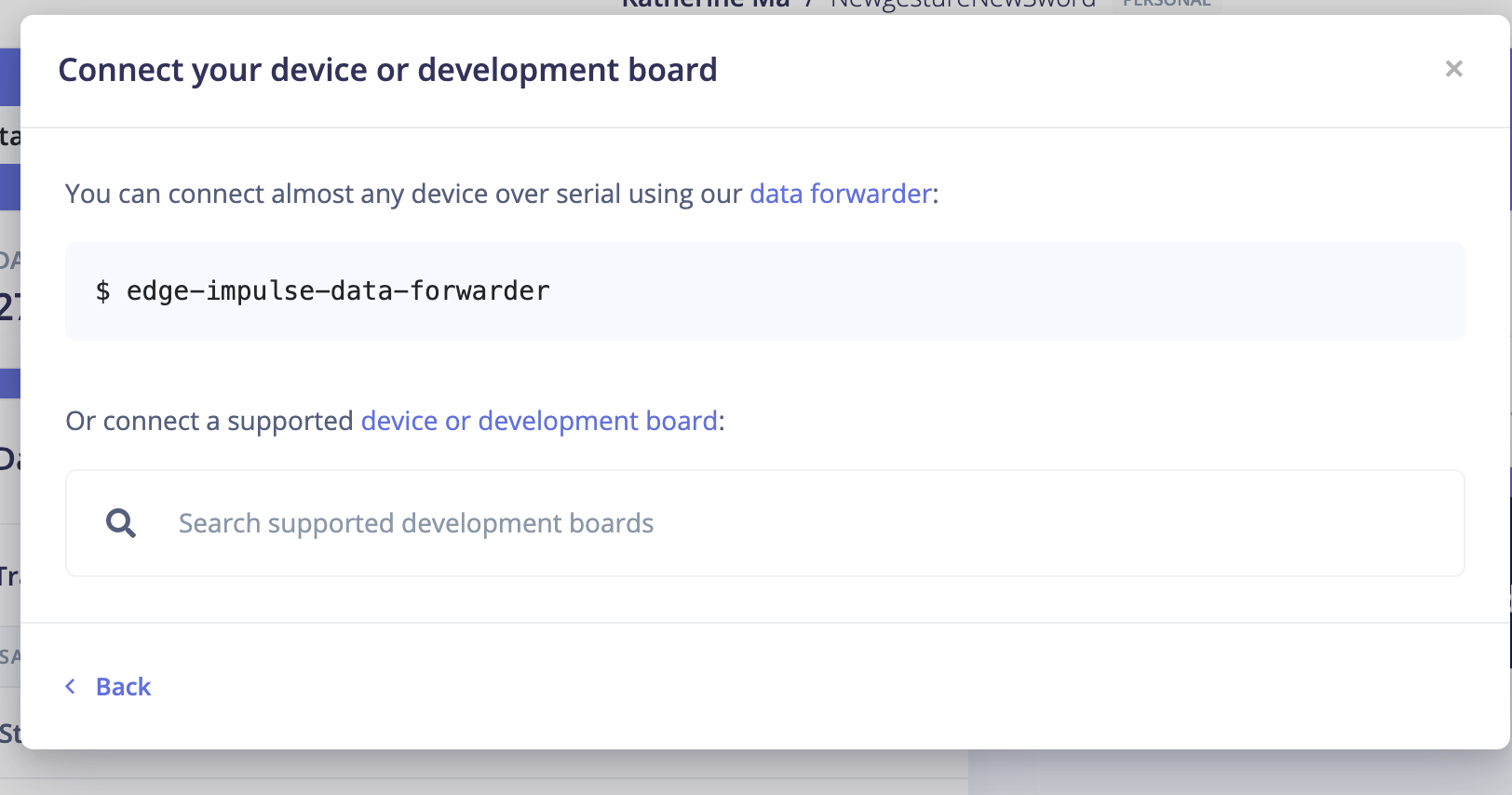
Step 4. Connect to Edge impulse and Forward Accelerometer data
Step 5: Go back to Edge Impluse and Start to train data!
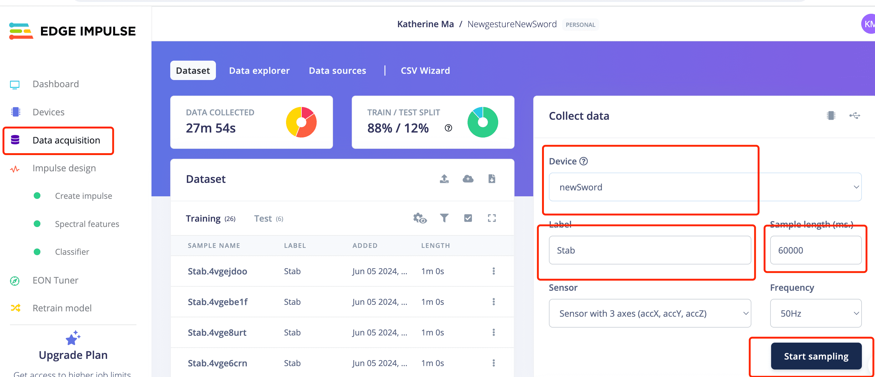
I have created two projects to train two sets of gestures.
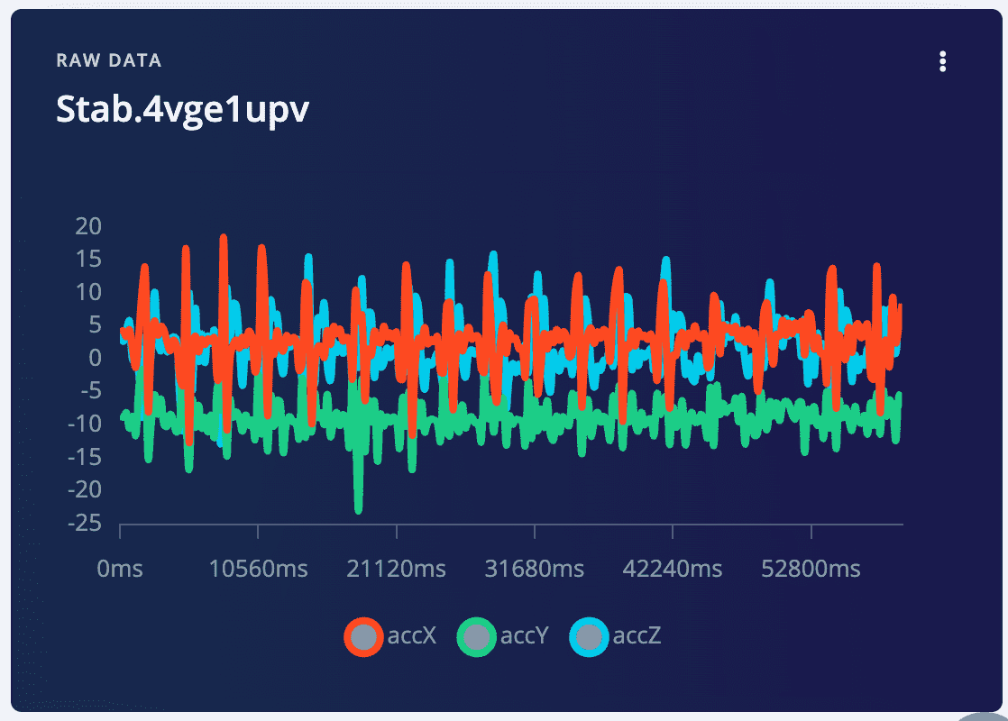
Stab gesture for the new sword
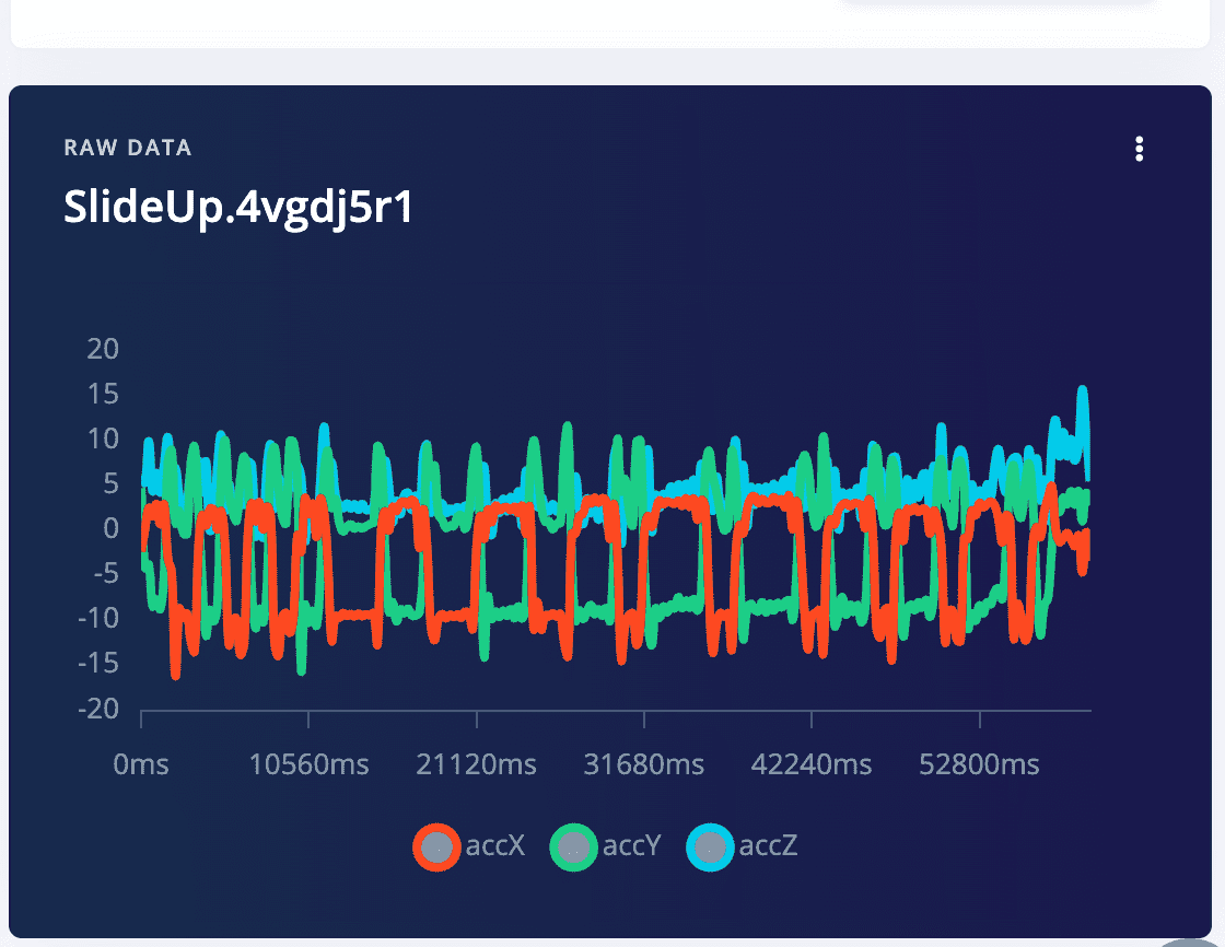
SlideUp gestures for the new sword
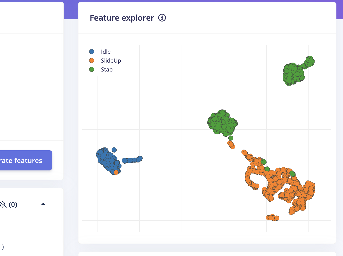
Step 6: Use the training data to generate feasures and classifiers.
6.1 Click on one recode of data, then you can see the three waves of the three accelerometer data
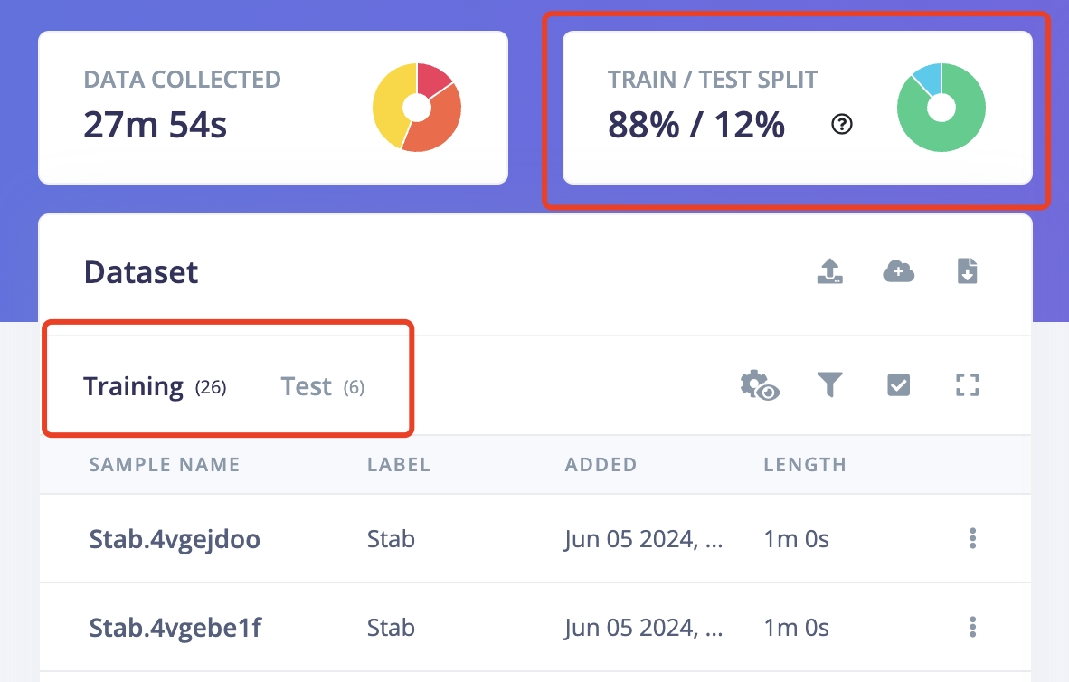
6.2 IMPORTANT!Another very important thing is to ensure that the percentage of training data and test data is 80% to 20%. Because you still need some data to test the recognition accuracy rate of the generated model. Click on "Train&Test" above, and you can see the ratio of training data and test data for each different label. Move the existing data to the test data or sample more data for testing.
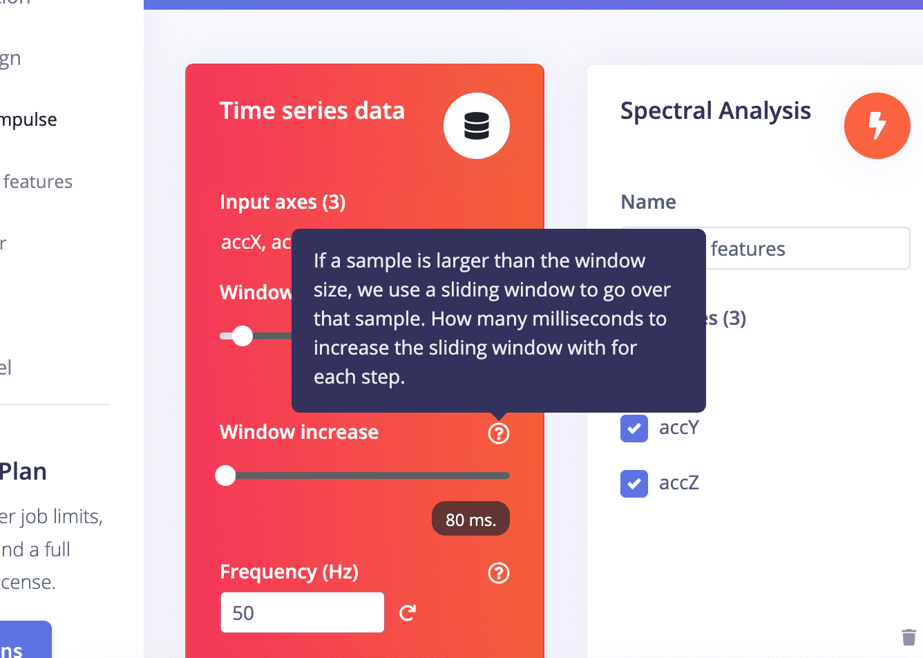
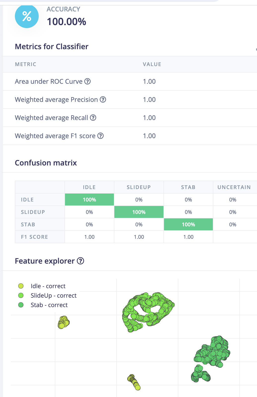
6.3 Spectral Features:
Try diffrent parameters and observe the result on the right side to choose the proper one if you don't want to go too deep.
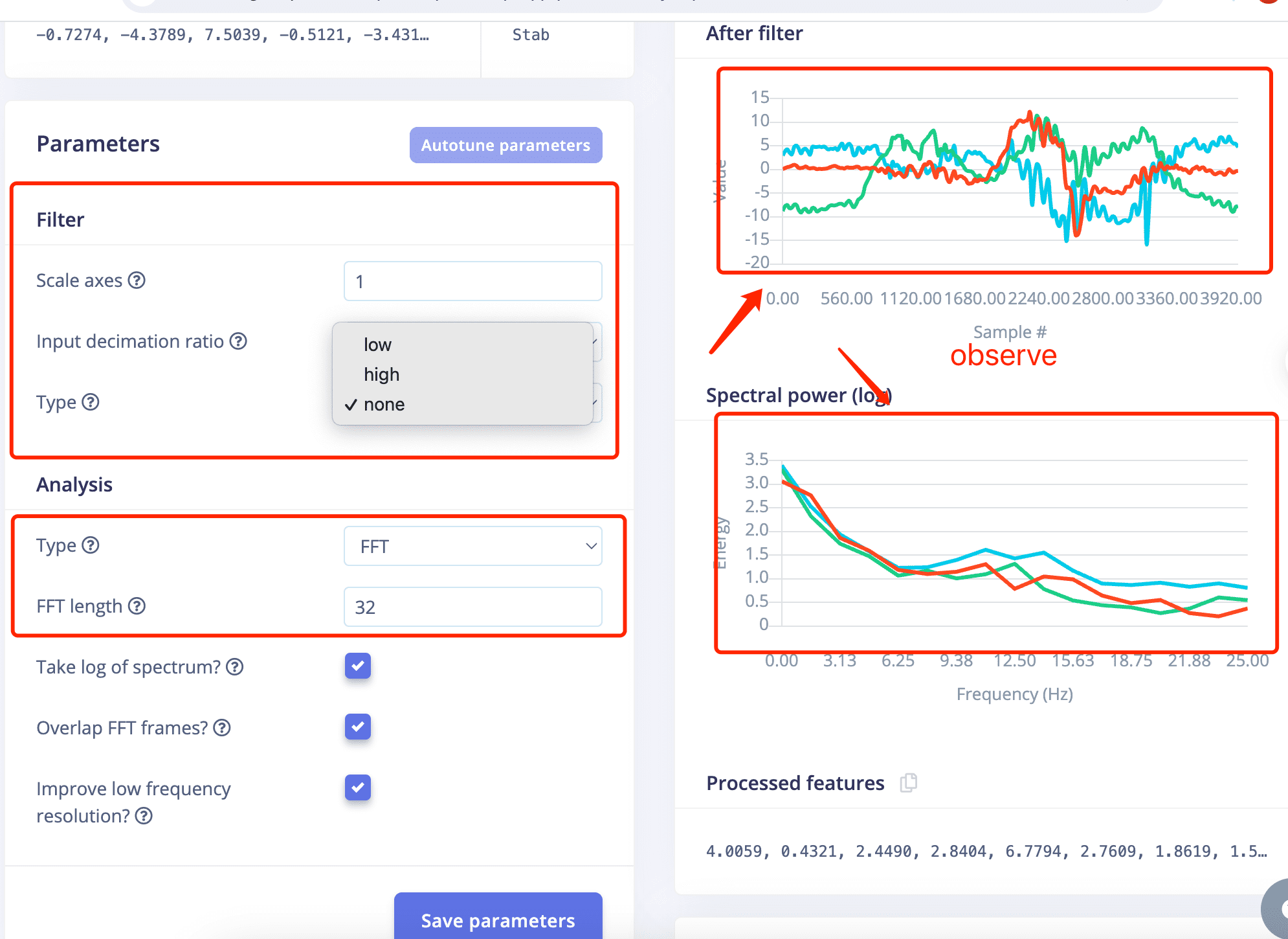
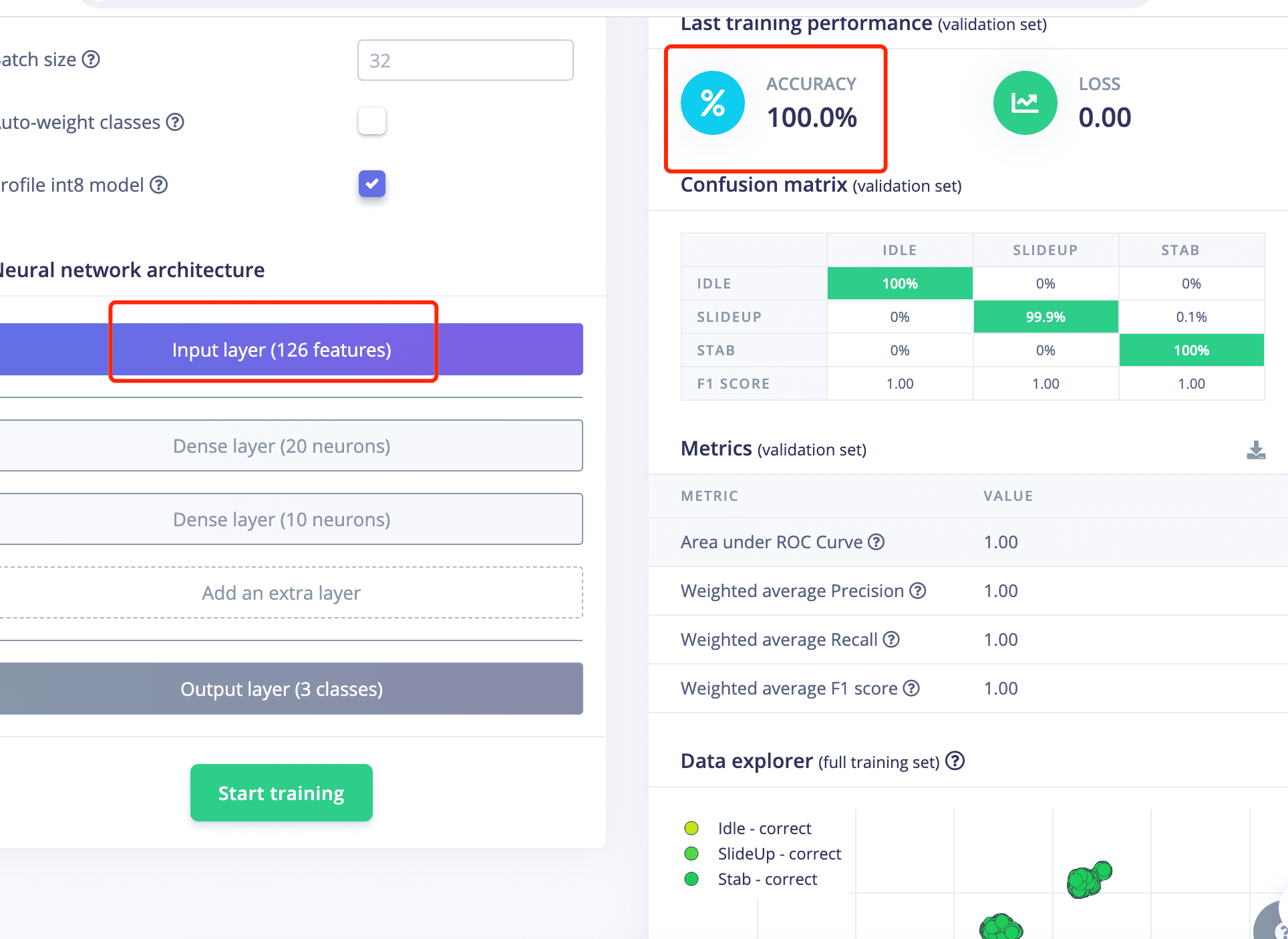
The Classification Accuracy is 100%.
Step7. Generate Arduino Libary
Go to "Deployment, search for "Arduino Library" , click Build


3.8 Assemble the Whole Sword
3.8.1 Put All Parts Together

3.9 Arduino Programming
 * Includes ---------------------------------------------------------------- */
/*#include  //replace the library name with yours*/
#include "NewgestureNewSword_inferencing.h"
#include "LSM6DS3.h"
#include
#ifdef __AVR__
#include   // Required for 16 MHz Adafruit Trinket
#endif

/* Constant defines -------------------------------------------------------- */
#define CONVERT_G_TO_MS2    9.80665f
#define MAX_ACCEPTED_RANGE  2.0f        // starting 03/2022, models are generated setting range to +-2, but this example use Arudino library which set range to +-4g. If you are using an older model, ignore this value and use 4.0f instead
#define INTERVAL_MS (1000 / (FREQUENCY_HZ + 1))
static unsigned long last_interval_ms = 0;


LSM6DS3 myIMU(I2C_MODE, 0x6A);  //I2C device address 0x6A


#define LED_PIN D10
#define LED_COUNT 22

// Declare our NeoPixel strip object:
Adafruit_NeoPixel strip(LED_COUNT, LED_PIN, NEO_GRB + NEO_KHZ800);
// Argument 1 = Number of pixels in NeoPixel strip
// Argument 2 = Arduino pin number (most are valid)
// Argument 3 = Pixel type flags, add together as needed:
//   NEO_KHZ800  800 KHz bitstream (most NeoPixel products w/WS2812 LEDs)
//   NEO_KHZ400  400 KHz (classic 'v1' (not v2) FLORA pixels, WS2811 drivers)
//   NEO_GRB     Pixels are wired for GRB bitstream (most NeoPixel products)
//   NEO_RGB     Pixels are wired for RGB bitstream (v1 FLORA pixels, not v2)
//   NEO_RGBW    Pixels are wired for RGBW bitstream (NeoPixel RGBW products)


unsigned long patternPrevious = 0;  // Previous Pattern Millis
int patternCurrent = 6;             // Current Pattern Number
int patternInterval = 10000;        // Pattern Interval (ms)
bool patternComplete = false;

int pixelInterval = 50;            // Pixel Interval (ms)
int pixelQueue = 0;                // Pattern Pixel Queue
int pixelCycle = 0;                // Pattern Pixel Cycle
uint16_t pixelNumber = LED_COUNT;  // Total Number of Pixels

static bool debug_nn = false; // Set this to true to see e.g. features generated from the raw signal

/**
* @brief      Arduino setup function
*/
void setup()
{
    // put your setup code here, to run once:
    Serial.begin(115200);
    // comment out the below line to cancel the wait for USB connection (needed for native USB)
    while (!Serial);
    Serial.println("Edge Impulse Inferencing Demo");

    if (!myIMU.begin()) {
        ei_printf("Failed to initialize IMU!\r\n");
    }
    else {
        ei_printf("IMU initialized\r\n");
    }

    if (EI_CLASSIFIER_RAW_SAMPLES_PER_FRAME != 3) {
        ei_printf("ERR: EI_CLASSIFIER_RAW_SAMPLES_PER_FRAME should be equal to 3 (the 3 sensor axes)\n");
        return;
    }
    #if defined(__AVR_ATtiny85__) && (F_CPU == 16000000)
       clock_prescale_set(clock_div_1);
    #endif
  // END of Trinket-specific code.

     strip.begin();             // INITIALIZE NeoPixel strip object (REQUIRED)
     strip.show();              // Turn OFF all pixels ASAP
     strip.setBrightness(127);  // Set BRIGHTNESS to about 1/5 (max = 255)
}

/**
 * @brief Return the sign of the number
 *
 * @param number
 * @return int 1 if positive (or 0) -1 if negative
 */
float ei_get_sign(float number) {
    return (number >= 0.0) ? 1.0 : -1.0;
}

/**
* @brief      Get data and run inferencing
*
* @param[in]  debug  Get debug info if true
*/
void loop()
{
    //ei_printf("\nStarting inferencing in 2 seconds...\n");

    delay(100);

    //ei_printf("Sampling...\n");

    // Allocate a buffer here for the values we'll read from the IMU
    float buffer[EI_CLASSIFIER_DSP_INPUT_FRAME_SIZE] = { 0 };
     char pregesture[5];
     const char* ptr = "hello";
     // 确保数组大小足够存储字符串和空字符


    for (size_t ix = 0; ix < EI_CLASSIFIER_DSP_INPUT_FRAME_SIZE; ix += 3) {
        // Determine the next tick (and then sleep later)
        uint64_t next_tick = micros() + (EI_CLASSIFIER_INTERVAL_MS * 1000);

        //IMU.readAcceleration(buffer[ix], buffer[ix + 1], buffer[ix + 2]);

        buffer[ix+0] = myIMU.readFloatAccelX();
        buffer[ix+1] = myIMU.readFloatAccelY();
        buffer[ix+2] = myIMU.readFloatAccelZ();


        for (int i = 0; i < 3; i++) {
            if (fabs(buffer[ix + i]) > MAX_ACCEPTED_RANGE) {
                buffer[ix + i] = ei_get_sign(buffer[ix + i]) * MAX_ACCEPTED_RANGE;
            }
        }

        buffer[ix + 0] *= CONVERT_G_TO_MS2;
        buffer[ix + 1] *= CONVERT_G_TO_MS2;
        buffer[ix + 2] *= CONVERT_G_TO_MS2;

        delayMicroseconds(next_tick - micros());

    }

    // Turn the raw buffer in a signal which we can the classify
    signal_t signal;
    int err = numpy::signal_from_buffer(buffer, EI_CLASSIFIER_DSP_INPUT_FRAME_SIZE, &signal);
    if (err != 0) {
        ei_printf("Failed to create signal from buffer (%d)\n", err);
        return;
    }

    // Run the classifier
    ei_impulse_result_t result = { 0 };

    err = run_classifier(&signal, &result, debug_nn);
    if (err != EI_IMPULSE_OK) {
        ei_printf("ERR: Failed to run classifier (%d)\n", err);
        return;
    }

    // print the predictions
   // ei_printf("Predictions ");
   // ei_printf("(DSP: %d ms., Classification: %d ms., Anomaly: %d ms.)",
   // result.timing.dsp, result.timing.classification, result.timing.anomaly);
    //ei_printf("\n");
    for (size_t ix = 0; ix < EI_CLASSIFIER_LABEL_COUNT; ix++) {

   // ei_printf("    %s: %.5f\n", result.classification[ix].label, result.classification[ix].value);
    if (result.classification[ix].value > .5) {

        ei_printf("Gesture now is %s \n", result.classification[ix]);
        if( result.classification[ix].label== "Idle")
        {

          rainbow(30);
         // delay(1000);
        }

       else if( result.classification[ix].label == "Stab")
        {
          theaterChase(strip.Color(200,   0, 0), 20); // Cyan
          Serial.println("Swipe red now");
          //delay(1000);
        }
        else if( result.classification[ix].label == "TakeItUP")
        {
          theaterChase(strip.Color(255,   0, 255), 20); // Cyan
          //Serial.println("ColorWipe Silver now");
          //delay(1000);
        }
        else if( result.classification[ix].label == "SlideUp")
        {
          colorWipe(strip.Color( 255, 0, 255), 30); // Anycolor
          Serial.println("ColorWipe Purple now");
          //delay(1000);
        }
        else
        {
          colorWipe(strip.Color( 126, 0, 89), 20); // Anycolor
        }

      }
    }
  }

    //  if (result.classification[ix].value > .5) {
    //     ei_printf("    %s: %.5f\n", result.classification[ix].label, result.classification[ix].value);
    // }
    // }

#if EI_CLASSIFIER_HAS_ANOMALY == 1
    ei_printf("anomaly score: %.3f\n", result.anomaly);
#endif


  uint32_t Wheel(byte WheelPos) {
    WheelPos = 255 - WheelPos;
    if (WheelPos < 85) {
      return strip.Color(255 - WheelPos * 3, 0, WheelPos * 3);
    }
    if (WheelPos < 170) {
      WheelPos -= 85;
      return strip.Color(0, WheelPos * 3, 255 - WheelPos * 3);
    }
    WheelPos -= 170;
    return strip.Color(WheelPos * 3, 255 - WheelPos * 3, 0);
  }

  void colorWipe(uint32_t color, int wait)
  {


    for (int i = 0; i < pixelNumber; i++)
    {                                  // For each pixel in strip...
        strip.setPixelColor(i, color); //  Set pixel's color (in RAM)
                    //  Update strip to matc
    }
    strip.show();
    delay(wait);
    for (int i = 0; i < pixelNumber; i++)
    {                                  // For each pixel in strip...
        strip.setPixelColor(i, strip.Color(0, 0, 0)); //  Set pixel's color (in RAM)
        strip.show();
        delay(wait-10);               //  Update strip to matc
    }
     for (int i = 0; i < pixelNumber; i++)
    {                                  // For each pixel in strip...
        strip.setPixelColor(i, color); //  Set pixel's color (in RAM)
        strip.show();
        delay(wait);               //  Update strip to matc
    }
  }

 //Theatre-style crawling lights with rainbow effect
  void theaterChaseRainbow(uint8_t wait) {
    if (pixelInterval != wait)
      pixelInterval = wait;  //  Update delay time
    for(int a = 0; a < 3; a++){
    for (int i = 0; i < pixelNumber; i += 3) {
      strip.setPixelColor(i + pixelQueue, Wheel((i + pixelCycle) % 255));  //  Update delay time
    }
    strip.show();
    for (int i = 0; i < pixelNumber; i += 3) {
      strip.setPixelColor(i + pixelQueue, strip.Color(127, 127, 127));  //  Update delay time
    }
    strip.clear();
    delay(wait);
    }
    pixelQueue++;  //  Advance current queue
    pixelCycle++;  //  Advance current cycle
    if (pixelQueue >= 3)
      pixelQueue = 0;  //  Loop
    if (pixelCycle >= 256)
      pixelCycle = 0;  //  Loop
  }


void theaterChase(uint32_t color, int wait) {

  static uint32_t loop_count = 0;
  static uint16_t current_pixel = 0;

  pixelInterval = wait;                   //  Update delay time

  strip.clear();

  for(int c=current_pixel; c < pixelNumber; c += 3) {
    strip.setPixelColor(c, color);
  }
  strip.show();

  current_pixel++;
  if (current_pixel >= 3) {
    current_pixel = 0;
    loop_count++;
  }

  if (loop_count >= 3) {
    current_pixel = 0;
    loop_count = 0;
  }
}

  void rainbow(int wait) {
  // Hue of first pixel runs 5 complete loops through the color wheel.
  // Color wheel has a range of 65536 but it's OK if we roll over, so
  // just count from 0 to 5*65536. Adding 256 to firstPixelHue each time
  // means we'll make 5*65536/256 = 1280 passes through this loop:
  for(long firstPixelHue = 0; firstPixelHue < 65536; firstPixelHue += 256) {
    // strip.rainbow() can take a single argument (first pixel hue) or
    // optionally a few extras: number of rainbow repetitions (default 1),
    // saturation and value (brightness) (both 0-255, similar to the
    // ColorHSV() function, default 255), and a true/false flag for whether
    // to apply gamma correction to provide 'truer' colors (default true).
    strip.rainbow(firstPixelHue);
    // Above line is equivalent to:
    // strip.rainbow(firstPixelHue, 1, 255, 255, true);
    strip.show(); // Update strip with new contents
    delay(wait);  // Pause for a moment
  }
}

#if !defined(EI_CLASSIFIER_SENSOR) || EI_CLASSIFIER_SENSOR != EI_CLASSIFIER_SENSOR_ACCELEROMETER
#error "Invalid model for current sensor"
#endif
The Interaction between the Sword and LED
Gesture Recognition Set1
Gesture Recognition Set2
Explaination of the Code
Includes Section
Constant Defines Section
CONVERT_G_TO_MS2 is defined to convert acceleration from g (gravitational acceleration units) to m/s² (meters per second squared).
MAX_ACCEPTED_RANGE is set to limit the range of accelerometer values.
INTERVAL_MS calculates the time interval based on the frequency.
last_interval_ms is used to keep track of the last time interval.
Object Declarations Section
LSM6DS3 object myIMU is created for IMU operations with the I2C address 0x6A.
Variables and objects for LED control are defined:
LED_PIN, LED_COUNT, and an Adafruit_NeoPixel object strip.
Various variables for pattern control and LED operations are initialized.
Setup Function
setup() function, serial communication is initialized at a baud rate of 115200. It waits for the serial connection if needed.
The IMU is initialized and a message is printed based on the success of the initialization.
Checks are made for the correct number of raw samples per frame.
Specific code for Arduino Trinket is included if applicable.
The NeoPixel strip is initialized and its properties like brightness are set.
Get Sign Function
ei_get_sign() function returns the sign of a given number as 1 for positive or zero values and -1 for negative values.
Loop Function
loop() function, a delay is introduced before the inferencing process starts.
A buffer is allocated to store acceleration values from the IMU.
A loop reads acceleration values from the IMU and performs range checks and conversions.
The acceleration values are converted into a signal for classification.
The classifier is run and the results are processed. Depending on the recognized gesture, different LED effects are triggered.
Several LED effect functions like
colorWipe(), theaterChaseRainbow(), theaterChase(), and rainbow() are defined to control the LED patterns and colors.